

Page 1

User’User’
User’
User’User’
ManualManual
Manual
ManualManual
VIA VIA
P4X533P4X533
VIA
P4X533
VIA VIA
P4X533P4X533
for Intel Socket 478 processorfor Intel Socket 478 processor
for Intel Socket 478 processor
for Intel Socket 478 processorfor Intel Socket 478 processor
TRADEMARK
mainboard mainboard
mainboard
mainboard mainboard
ss
s
ss
6000002P4X510
All products and company names are trademarks or registered
trademarks of their respective holders.
These specifications are subject to change without notice.
Manual Revision 1.0
March 15, 2004
Page 2

DISCLAIMER OF WARRANTIES:
THERE ARE NO WARRANTIES WHICH EXTEND BEYOND THE
DESCRIPTION ON THE FACE OF THE MANUFACTURER LIMITED
WARRANTY. THE MANUFACTURER EXPRESSLY EXCLUDES ALL
OTHER WARRANTIES, EXPRESS OR IMPLIED, REGARDING ITS
PRODUCTS; INCLUDING ANY IMPLIED WARRANTIES OF
MERCHANTABILITY, FITNESS FOR A PARTICULAR PURPOSE OR
NONINFRINGEMENT. THIS DISCLAIMER OF WARRANTIES SHALL
APPLY TO THE EXTENT ALLOWED UNDER LOCAL LAWS IN THE
COUNTRY PURCHASED IN WHICH LOCAL LAWS DO NOT ALLOW
OR LIMIT THE EXCLUSION OF THE IMPLIED WARRANTIES.
ii
Page 3

Table of Contents
Section 1 Introduction
Package Contents ...................................................... 1-1
Intel Pentium 4 Processors......................................... 1-2
Accelerated Graphics Port ......................................... 1-2
Ultra ATA66/100/133 .................................................. 1-2
Hardware Monitoring ................................................. 1-2
LAN ............................................................................ 1-3
S-ATA ........................................................................ 1-3
Mainboard Form-Factor ............................................. 1-4
I/O Shield Connector.................................................. 1-5
Power-On/Off (Remote) .............................................. 1-5
System Block Diagram ............................................... 1-6
Section 2 Features
Mainboard Features ................................................... 2-1
Section 3 Installation
Mainboard Layout ..................................................... 3-1
Easy Installation Procedure
CPU Installation ......................................................... 3-2
Jumper Settings .......................................................... 3-4
System Memory Configuration .................................. 3-5
Expansion slots .......................................................... 3-7
Device Connectors..................................................... 3-9
Page
Section 4 BIOS Setup
Main Menu ................................................................ 4-1
Standard CMOS Setup ............................................... 4- 2
Advanced Setup ........................................................ 4- 3
iii
Page 4

Power Management Setup ......................................... 4- 6
PCI/Plug and Play Setup ............................................ 4- 8
Load Optimal Settings ................................................ 4- 9
Load Best Performance Settings ................................ 4- 9
Features Setup ........................................................... 4- 9
CPU PnP Setup........................................................... 4- 11
Hardware Monitor ...................................................... 4- 12
Change Password ...................................................... 4- 13
Exit... ......................................................................... 4- 13
Section 5 S-ATA RAID Configuration
Introduction ............................................................... 5- 1
VIA SATA RAID Features .......................................... 5- 3
Enable RAID Function ............................................... 5- 4
Section 6 Driver Installation
Easy Driver Installation .............................................. 6- 1
C-Media Audio Configuration Brief guide ................. 6- 2
Appendix Appendix A
VIA RAID BIOS Utility ................................................ A-1
Appendix B
GHOST 7 Quick User’s Guide (Optional) ................... B-1
iv
Page 5
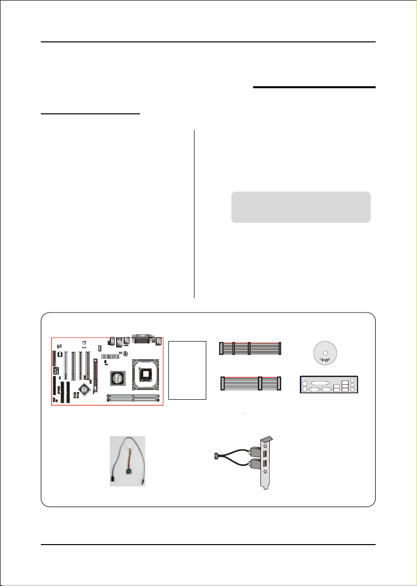
Package Contents
Introduction
Section 1
INTRODUCTION
Contents
A. Mainboard
B. User’s manual
C. Floppy drive cable
D. HDD drive cable
E. CD (drivers and utilities)
F. I/O Shield
A
USER’S
MANUAL
B
Optional Items
G. S-ATA data and power cable
H. Extra USB2.0 port cable
If you need the optional item, please
contact your dealer for assistance.
C
D
E
F
G
H
Page 1-1
Page 6

Introduction
Intel® Pentium® 4 processors
The Intel Pentium 4 processor, Intel's most advanced, most powerful processor for
desktop PCs and entry-level workstations, is based on Intel NetBurst
TM
microarchitecture. The Pentium 4 processor is designed to deliver performance
across applications and usages where end-users can truly appreciate and experience
the performance. These applications include Internet audio and streaming video,
image processing, video content creation, speech, 3D, CAD, games, multimedia, and
multi-tasking user environments. The Pentium 4 processor delivers this world-class
performance for consumer enthusiasts and business professional desktop PC users
as well as for entry-level workstation users.
Intel adds support for Hyper-Threading Technology to the Pentium 4 processor
family. HT Technology allows a single, physical Pentium 4 processor to function as
two logical processor for next generation multi threaded application.
For more information about all the new features the Pentium 4 delivers check out
the Intel website at http://www.intel.com
Accelerated Graphics Port (AGP)
The AGP slot on the board is compliant with the new AGP 3.0 specification. This
new specification enhances the functionality of the original AGP specification by
allowing 8X data transfers ( 8 data samples per clock) resulting in maximum band-
width of 2.1GB/s. In addition, it defines 1.5 volt power supply operation. Complying
with this specification, this board supports external AGP-8X/4X cards with Fast
Write Transactions. Only 1.5V AGP cards are supported.
Ultra ATA/66/100/133
This board provides an Ultra ATA100/133 Bus Master IDE controller. This controller
supports Ultra ATA100/133 protocols which are ideal to support demanding applica-
tions such as real-time video, multimedia, and a high performance operating system.
A new IDE cable is required for Ultra ATA100/133; this cable is an 80-pin conductor
cable which is backward compatible with ATA/33 connectors.
Hardware Monitoring
Hardware monitoring enables you to monitor various aspects of the system operation
and status. The features include CPU temperature, voltage and fan speed in RPMs.
Page 1-2
Page 7

Introduction
LAN
This mainboard is optionally mounted with a LAN chipset. It allows the mainboard to
connect to a local area network by means of a network hub.
Serial ATA
Support Serial ATA ,an evolutionary replacement for Parallel ATA IDE storage
interface .Increases the peak data transfer speed up to 150MB/sec and allows future
enhancements to the computing platform.
Page 1-3
Page 8

Introduction
Mainboard Form-Factor
This board is designed with ATX form factor - the latest industry standard for
chassis design. The ATX form factor is essentially a Baby-AT baseboard rotated
90 degrees within the chassis enclosure and a new mounting configuration for
the power supply. With these changes the processor is relocated away from the
expansion slots, allowing them all to hold full length add-in cards. ATX defines a
double height aperture to the rear of the chassis which can be used to host a
wide range of onboard I/O. Only the size and position of this aperture is defined,
allowing PC manufacturers to add new I/O features (e.g.; TV input, TV output,
joystick, modem, LAN, audio, etc.) to systems. This will help systems integrators
differentiate their products in the marketplace, and better meet your needs.
• By integrating more I/O down onto the board and better positioning the hard
drive and floppy connectors material cost of cables and add-in cards is
reduced.
• By reducing the number of cables and components in the system, manufacturing time and inventory holding costs are reduced and reliability will
increase.
• By using an optimized power supply, it's possible to reduce cooling costs
and lower acoustical noise. An ATX power supply, which has a sidemounted fan, allows direct cooling of the processor and add-in cards making
a secondary fan or active heatsink unnecessary in most system applications.
CNR slot
PCI slots
AGP slot
Floppy
connector
IDE connectors
Page 1-4
Expandable I/O
Figure 2: Summary of ATX chassis features
3 1/2-inch
Bay
AT X
Power
Supply
5 1/4-inch
Bay
Single chassis
fan for system
ATX 12V power
connector
ATX power connector
CPU socket
Page 9
Introduction
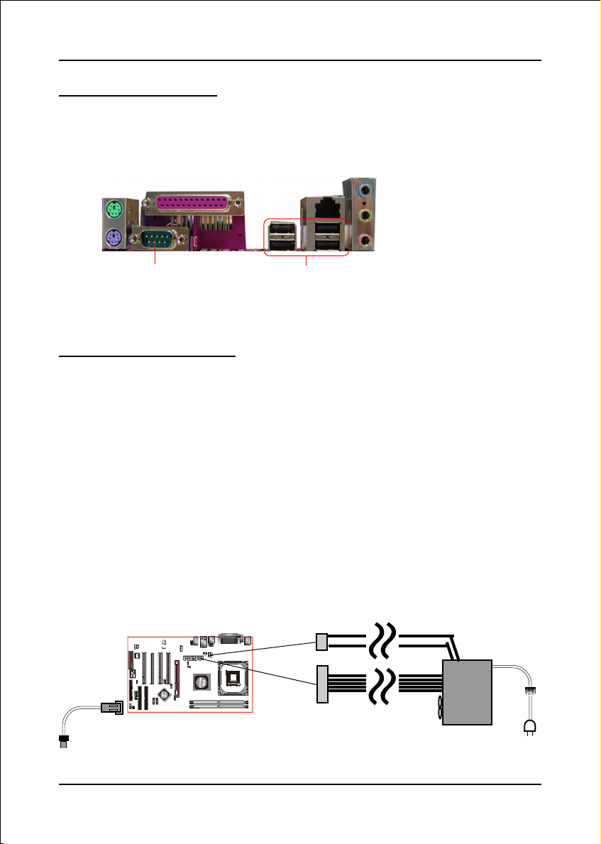
I/O Shield Connector
The I/O back panel for this mainboard is shown below (Figure 3). When installing
the mainboard into the computer case, use the bundled I/O shield to protect this
back panel.
Parallel Port
PS/2
Mouse
PS/2
Keyboard
RJ45
LAN
Line-in/Rear out (Light blue)
Line-out/Front out (Lime)
Mic-in/Center&Subwoofer (Pink)
COM1
USB2.0 x 4 ports
Figure 3: I/O ports
Power-On/Off (Remote)
This board has a 20-pin ATX and a 4-pin ATX12V power supply connector (Figure 4).
For power supplies that support the Remote On/Off feature, this should be connected
to the mainboard front panel PW_ON connector for the computer power On/Off button.
This board has been designed with “Soft Off" function. You can turn off the system
in two ways: by pressing the front panel power On/Off button or using the "Soft
Off" function that can be controlled by an operating system such as Windows®XP/
ME/2000/98.
Note: For ma intai ning the DDR SDRAM power during STR (ACPI S3) function, it is strongly
recommended to use power supplies that have a +5VSB current of (>=) 2A. Please check the
5VSB’s specification printed on the power supply’s outer case.
Note: The board requires a minimum of 250 Watt power supply to operate. Your system configura-
tion (amount of memory, add-in cards, peripherals, etc.) may exceed this minimum power
requirement. To ensure that adequate power is provided, use a 300 Watt (or higher) power
supply.
12V 4-pin
20-pin
POWER SUPPLY
PW-ON
Case (chassis) Power ON/OFF button (PW-ON)
Figure 4: Simple ATX power ON/OFF controller
Page 1-5
Page 10
Introduction
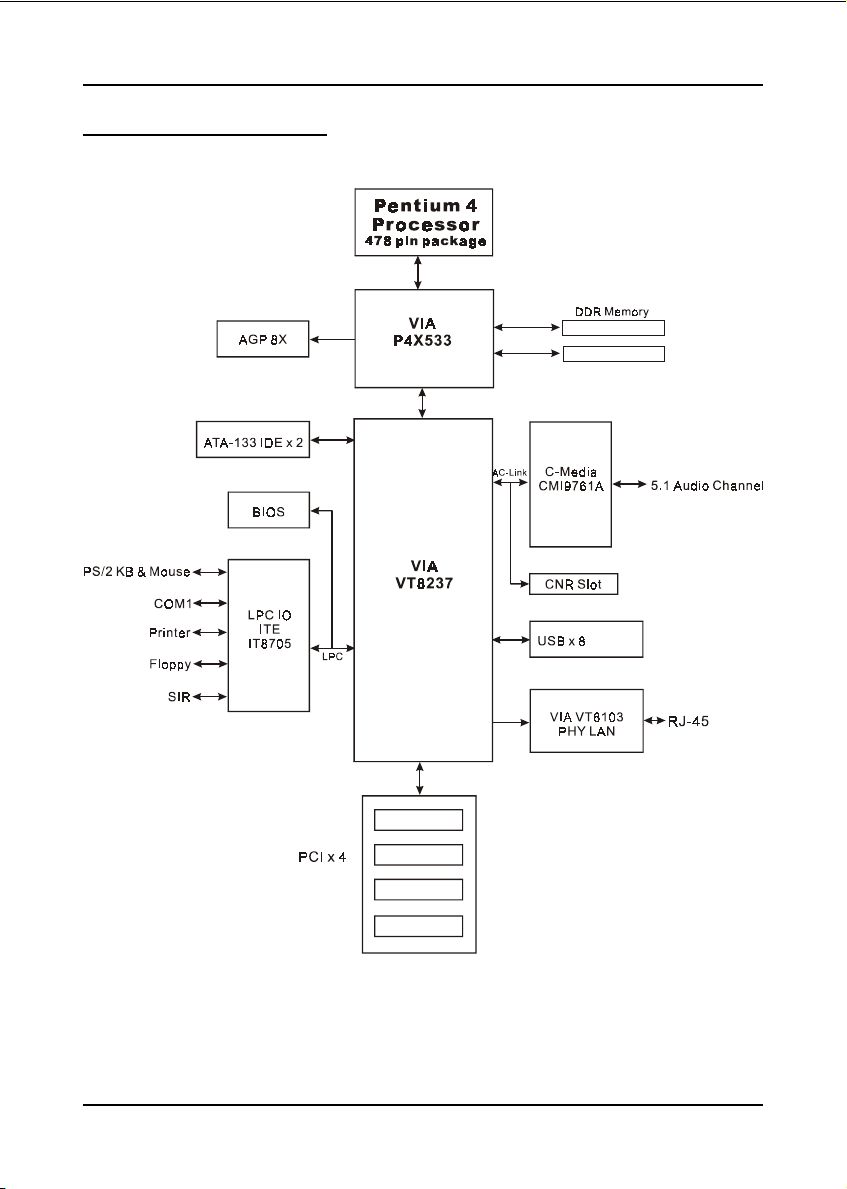
System Block Diagram
Page 1-6
Figure 5: System Block Diagram
Page 11

Mainboard Features
Socket-478 Processor
Support Intel® Pentium® 4 processors Northwood/Willamette up to 3.06GHz
in mPGA478 socket with 400/533 MHz front-side system bus
Support Intel® Hyper-Threading Technology
Support Intel® Celeron® processors up to 2.6GHz in mPGA478 socket with
400 MHz front-side system bus
Chipset
VIA P4X533 + 8237 AGPset
System Memory
Two 184-pin DDR SDRAM DIMM sockets
Support single or double-sided 2.5v DDR-266/333 DIMMs in 128/256/
512Mb technologies
Support up to 2 GB system memory
Features
Section 2
FEATURES
Expansion Slots
Four PCI connectors compliant with PCI v2.2
One 1.5v AGP- 8X/4X connector compliant with AGP v3.0
One CNR slot.
IDE
Two IDE interfaces (up to 4 IDE devices) with UDMA-33, ATA-66/100/133
support from embedded IDE controller
USB
Eight USB connectors compliant with USB2.0 from embedded USB
controller (4 connectors at rear panel)
Page 2-1
Page 12

Features
S-ATA
LAN
Audio
I/O
Two S-ATA ports with up to 150MBps bandwidth with RAID 0,1 Support.
100Mb Fast Ethernet from onboard VIA VT6103 PHY.
Onboard C-Media CMI9761A selectable 2 or 6-CH audio CODEC (AC97
v2.3 compliant)
Support CD-In
Rear panel audio jacks configuration;
For 2-channel mode; stereo Line-out (Lime), stereo Line-In (Light blue) and
Mic-In (Pink)
For 6-channel mode; Front stereo-out(Lime), Rear stereo-out (Light blue),
Center and Sub-woofer (Pink)
Support Front panel audio for MIC-In and stereo Line-out only.
(Front panel Line-out electrically shared with rear panel Line-out).
Onboard ITE IT8705F LPC bus I/O controller
Legacy peripheral interface for PS/2 keyboard & mouse, FDD, Parallel, One
Serial, Game and IrDA (v1.0 compliant), …
Support Hardware Monitoring function such as fan speed monitoring and
CPU temperature.
BIOS
2 Mb Flash EEPROM with AMI Plug & Play BIOS
Special Features
Support Wake-On-LAN by PME
Support Asynchronous clocking mode between FSB and AGP/PCI
Form Factor:
305mm x 190mm x 40mm, ATX Size
Page 2-2
Page 13

Mainboard Layout
Installation
Section 3
INSTALLATION
Page 3-1
Page 14
Installation
Easy Installation Procedure
The following must be completed before powering on your new system:
3-1. CPU Installation
3-2. Jumper Settings
3-3. System Memory Configuration
3-4. Expansion Slots
3-5. Device Connectors
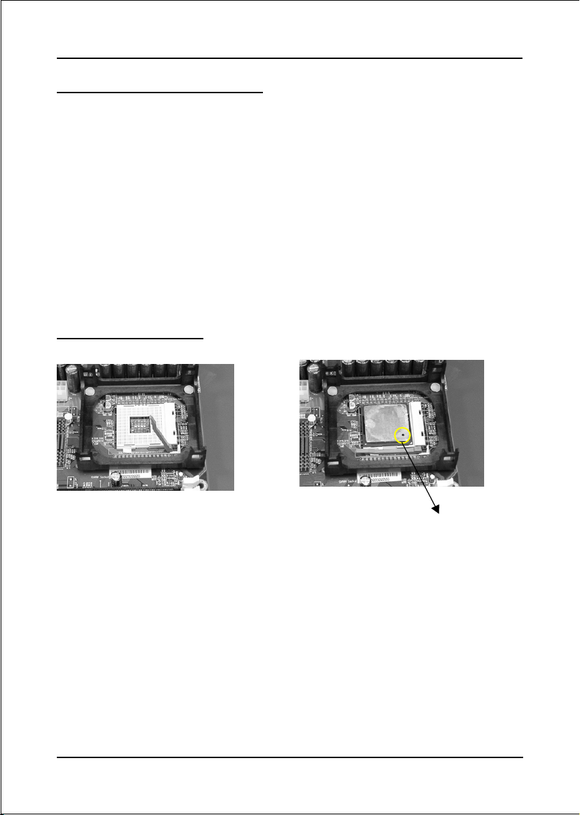
3-1 CPU Installation
<Figure 1>
Step 1
Open the socket by raising the actuation
lever.
Page 3-2
<Figure 2>
Pin 1
Step 2
Align pin 1 on the CPU with pin 1 on
the CPU socket as shown in the
illustration above. The CPU is keyed to
prevent incorrect insertion. Don’t force
the processor into the socket. If it does
not go in easily, check for mis-orienta-
tion and reinsert the CPU.
Make sure the processor is fully
inserted into the socket.
Page 15

Installation
<Figure 3>
Step 3
Close the socket by lowering and
locking the actuation lever.
Step 4
Apply thermal compound to the top of
the CPU and install the heatsink as
<Figure 4>
shown.
<Figure 5> <Figure 6>
Step 5
Install the cooling fan assembly. Press
the two clips in the direction of the
arrows shown in Figure 5 to secure the
Step 6
Plug the CPU fan power into the
mainboard’s CPU fan connector.
The installation is complete.
assembly to the CPU socket.
NOTES:
• Damage to Intel Pentium
TM
4 processors might result if installed with
incorrect CPU fan and heatsink assemblies. Use Intel’s design thermal
solution shown in the illustrations above: an active heatsink; an extruded
aluminum heatsink base; and a fan attached to the top of the fin array.
• Apply heatsink thermal compound or paste to the CPU to avoid CPU
overheating and damage.
• In accordance with Intel Corp. specifications, do not install a CPU over
50 times to avoid bending the pins and damaging the CPU.
Page 3-3
Page 16

Installation
3-2 Jumper Settings
JCMOS1:
Clear CMOS data Jumper
If the CMOS data becomes corrupted or you
forgot the supervisor or user password, clear
the CMOS data to reconfigure the system back
to the default values stored in the ROM BIOS.
Settings:
1
1-2: Normal (Default)
2-3: Clear CMOS
To CMOS Clear data, please follow the steps below.
1. Turn off the system.
2. Change the jumper from “1-2” to “2-3” position
for a few seconds.
3. Replace the jumper on to the “1-2” position.
4. Turn on the system and hold down the <Del>
key to enter BIOS setup.
JP2/JP3:
CPU FSB Select Jumper
These jumper are used to select the front
side bus of the CPU installed on the
mainboard.
JP3
JP2
JP2
JP3
1
J P2 J P3 Settings:
1
2-3 2-3 100MHz (Default)
1-2 2-3 133MHz
Page 3-4
Note: Overclocking may cause system instability and
are not guaranteed to provide better system
performance.
Page 17
Installation
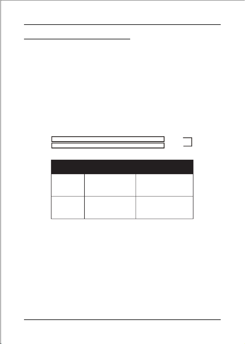
3-3 System Memory Configuration
The mainboard accommodates two PC2100/PC2700 184-pin DIMMs (Dual In-line
Memory Modules):
• Supports up to 2.0GB of 266/333 MHz DDR SDRAM.
• Supports up to 2 DDR DIMMs (refer to Table 1).
• Supports unbuffered non-ECC DIMMs only.
• Supports configurations defined in the JEDEC DDR DIMM specification
Figure 7 and Table 1 show two possible memory configurations.
<Figure 7>
<Table 1>
DDR DIMM 1
DDR DIMM 2
yromeMlatoT
BG1=
mumixaM
BG2=
mumixaM
1MMIDRDD
)1/0knaB(
*MARDSRDD
,BM652,BM821,BM46
1X*BG1,BM215
*MARDSRDD
1X*BG1,BM215
enoN
,BM652,BM821,BM46
Bank 0/1
Bank 2/3
)3/2knaB(
*MARDSRDD
1X*BG1,BM215
DDR
Synchronous
DRAM
2MMIDRDD
,BM652,BM821,BM46
* DDR SDRAM supports 128, 256, 512MB and 1GB DIMM modules using
512Mb technology.
NOTES:
• Using non-compliant memory with higher bus speeds (overclocking)
may severely compromise the integrity of the system.
Page 3-5
Page 18
Installation
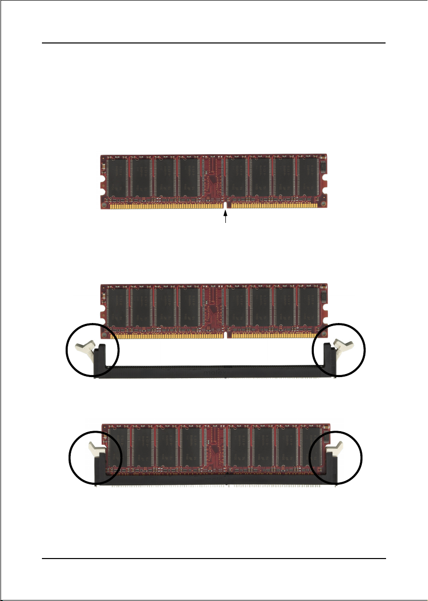
DIMM Module Installation
Figure 9 displays the notch on the DDR DIMM memory module.
DIMMs have 184 pins and one notch that matches with the DDR DIMM socket.
DIMM modules are installed by placing the chip firmly into the socket and
pressing straight down as shown in figure 10 until the white clips close and the
module fits tightly into the DIMM socket (figure 11).
CENTER KEY ZONE
(2.5 V DRAM)
Figure 9 - DIMM notch
Figure 10 - DIMM module clips before installation
Figure 11 - DIMM module clip after installation
To remove the DIMM module press down the white clips and the module will be
ejected from the socket.
Page 3-6
Page 19
Installation
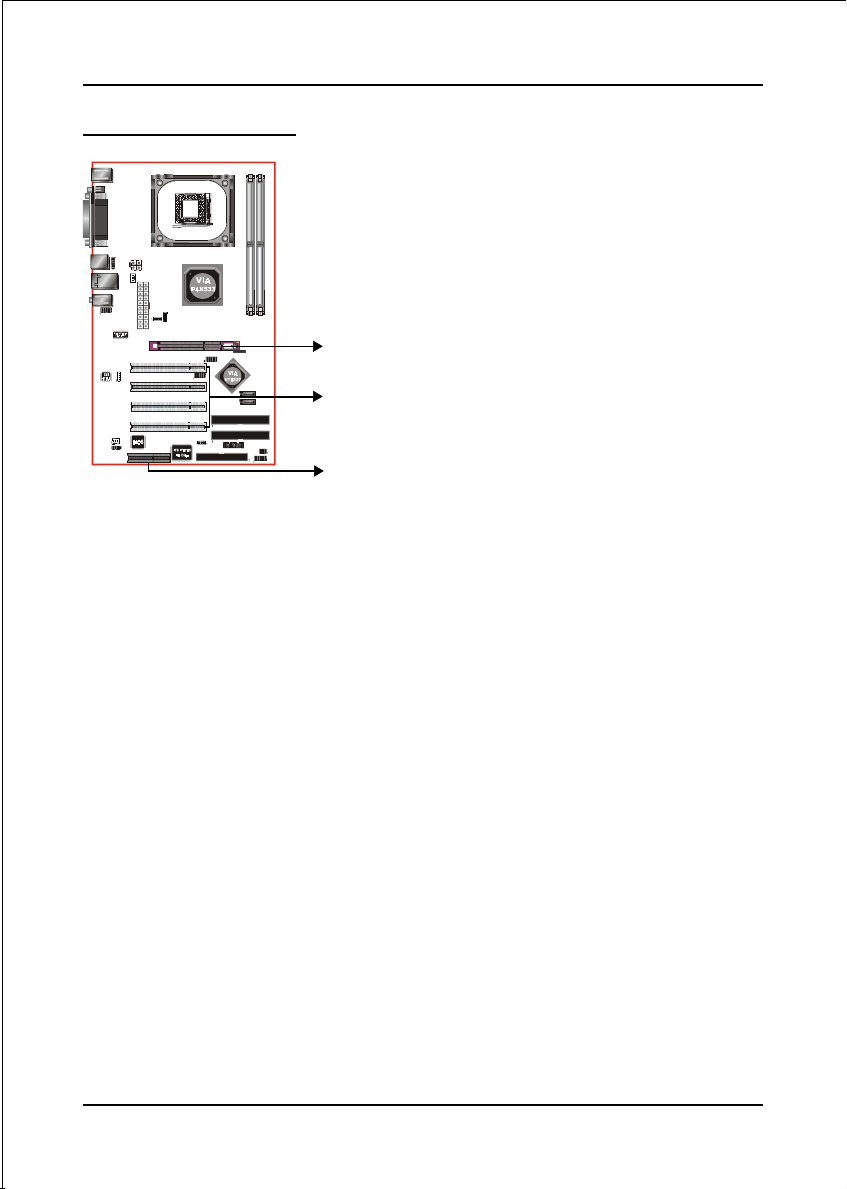
3-4 Expansion Slots
AGP Slot
The mainboard is equipped with an AGP
slot. Make sure you install a card that
supports the 1.5V specification.
PCI Slots
AGP Slot
The mainboard is equipped with 4 PCI slots.
CNR Slot
PCI Slots
You can install the CNR (Communication
and Networking Riser) cards in this slot,
CNR Slot
including LAN, Modem and audio
functions.
Installing an Expansion Card
The steps below assume that the mainboard is already installed in the system chassis.
1. Make sure the PC and all other peripheral devices connected to its has been
powered down.
2. Disconnect all power cords and cables.
3. Remove the system unit cover.
4. Remove the bracket of the slot that you intend to use. (You need to remove the
screw in order to remove the bracket.)
5. Align the card above the slot then press it down firmly until it is completely
seated in the slot.
6. Secure the card to the chassis with the screw you removed in step 4.
7. Replace the system unit cover.
8. Power on the PC.
9. Enter the BIOS step program to make the necessary settings.
10. Save the settings and restart the PC.
11. Install the software drivers of the expansion cards, if necessary.
Page 3-7
Page 20
Installation
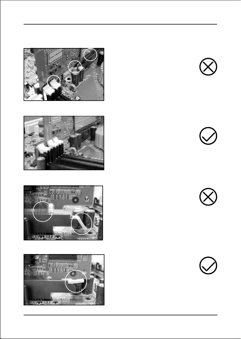
AGP Card Installation Caution
1. AGP card component is blocked
by DIMM socket lock.
2. AGP slot clicker is not locked.
3. AGP card edge connector is not
inserted properly.
1. AGP card component is not
blocked by DIMM socket lock.
2. AGP slot clicker is locked.
3. AGP card edge connector is
inserted properly.
Page 3-8
1. AGP slot clicker is not locked.
2. AGP card edge connector is not
inserted properly.
1. AGP slot clicker is locked.
2. AGP card edge connector is
inserted properly.
Page 21
Installation
3-5 Connectors
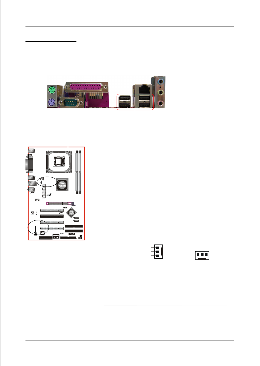
The I/O back panel for this mainboard is shown below (Figure 12). When installing
the mainboard into the computer case, use the bundled I/O shield to protect this
back panel.
Parallel Port
PS/2
Mouse
PS/2
Keyboard
RJ45
LAN
Line-in/Rear out (Light blue)
Line-out/Front out (Lime)
Mic-in/Center&Subwoofer (Pink)
JCPU_FAN
JSYSTEM_FAN
COM1
USB2.0 x 4 ports
Figure 12 - I/O Ports
JCPU_FAN / JSYSTEM_FAN:
CPU/Chassis Fan Power Connectors
JCPU_FAN: The CPU must be kept cool by
using a heatsink with fan assembly.
JSYSTEM_FAN: The chassis fan will provide
adequate airflow throughout the
chassis to prevent overheating the
CPU.
JCPU_FAN
Ground
+12V
Sense
The system is capable of monitoring the fan speed in
RPM (Revolutions Per Minute). Refer to the PC
Health Status submenu of the BIOS for the current
speed of the CPU fan and chassis fan.
JSYSTEM_FAN
+12V
Ground
Sense
Page 3-9
Page 22

Installation
34 33
1
2
FDD
PJ1
CN2
IDE1
IDE2
FDD
40 39
2
IDE1/IDE2
FDD: Floppy Controller Connector
This mainboard connects floppy disk drive.
IDE1/IDE2: Ultra DMA-66/100/133 Primary/Secondary
IDE Connector
This mainboard is equipped with 2 IDE connectors
to support up to 4 ATA-133 IDE drives.
It supports PIO and DMA mode operations for
maximum data transfer rate of 133MB/sec per channel.
When using two IDE drives, one must be set to
Master mode and the other to Slave mode. Refer to
your disk drive user’s manual for information about
selecting the proper drive switch settings.
1
CN2: 20-pin ATX Power Connector
PJ1: 4-pin ATX12V Power Connector
The mainboard is equipped with a standard 20-pin
ATX main power connector and a 4-pin +12V
power connector for connecting an ATX12V
power supply. The plugs of the power cables are
designed to fit in only one orientation. Insert the
plugs into the connectors until they fit in place.
4
3
+12V+12V
GroundGround
2
1
PJ1
Page 3-10
10
1
CN2
Caution:
The CN2 and PJ1 Power Connector must be used simultaneously or
else this system will not boot-up.
20
+5V+12V
+5V5VSB
-5VPW-OK
GroundGround
Ground+5V
GroundGround
PS-ON+5V
GroundGround
-12V3.3V
3.3V3.3V
11
The board requires a minimum of 250 Watt power
supply to operate. Your system configuration (amount
of memory, add-in cards, peripherals, etc.) may
exceed this minimum power requirement. To ensure
that adequate power, use a 300 Watt or greater power
supply.
Page 23

Installation
CFPA: Front Panel Audio Connector
When the jumpers are removed this connector can
be used for front panel audio. The front panel
phone jack should have “normal close” switch.
Without phone plug inserted, the rear panel audio is
enabled. With phone plug inserted, the rear panel
audio will be disabled.
1
MIC_In
Front Line-out-R
Settings:
Pins (5-6) & (9-10) Short (default): Only the onboard rear
panel audio jack can be used.
Pins (5-6) & (9-10) Open: Only front panel audio jack can
be used.
In 2-Channel audio mode, Mic-In is shared for both front panel and rear panel.
NC
Front Line-out-L
9210
In 6-Channel audio mode, the Mic-In is dedicated for front panel use, and rear
panel Mic-In function will switch to Center and Subwoofer support.
GND
+5V
Rear Line-out-FR
Key
Rear Line-out-FL
CD2: CD Audio_IN Connector
The CD2 connector is used to receive audio form a
CD-ROM drive, TV tuner or MPEG card.
CD2
CD_IN_Right
CD_Reference
CD_IN_Left
1
Page 3-11
Page 24
Installation
CUSB3
CUSB2
CN3
CN4
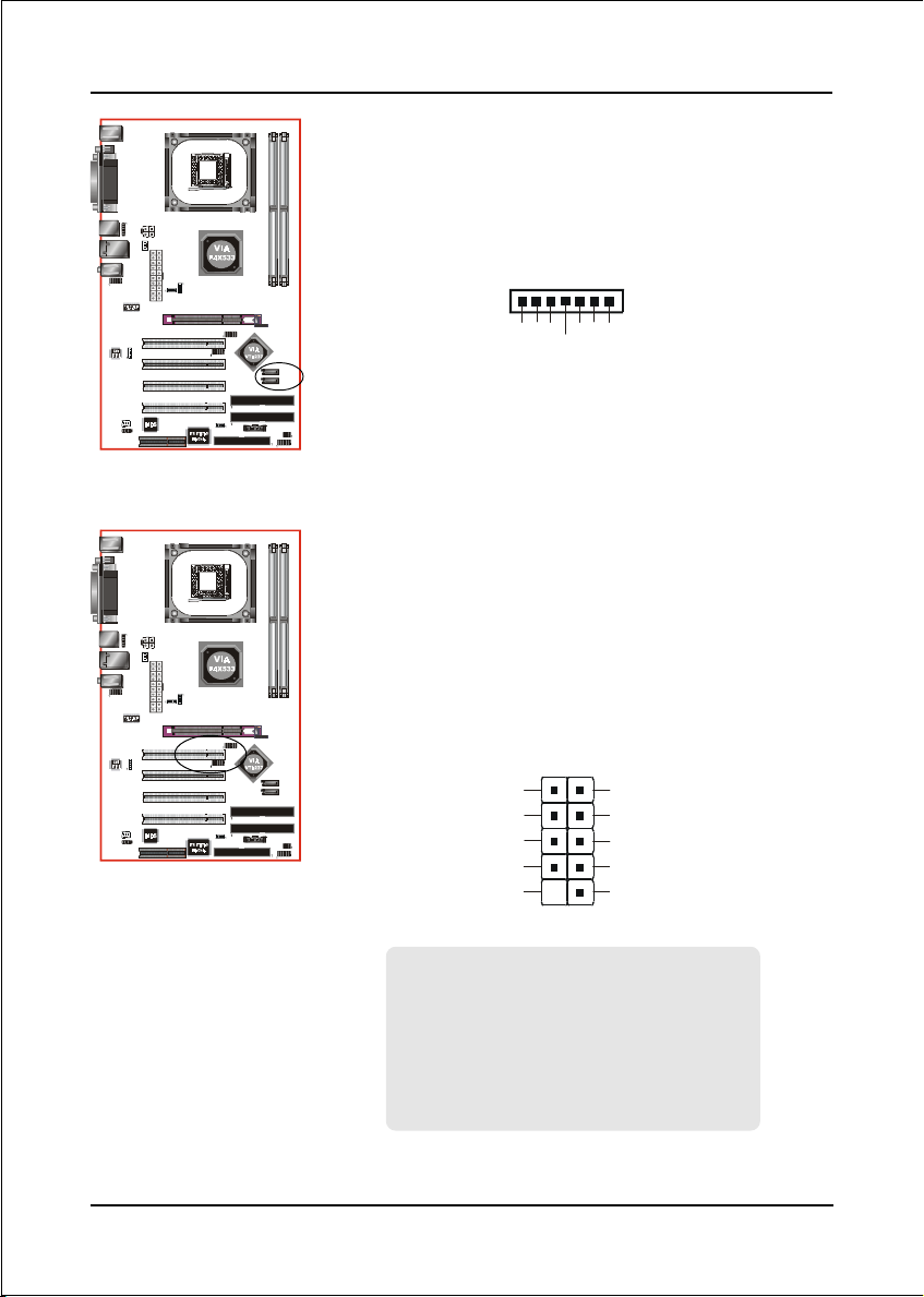
CN3 / CN4: Serial ATA Connectors
These connectors enable you to connect two Serial
ATA devices that conform to the Serial ATA
specification.
1
GND
B-B+
A+
GND
A-
GND
CUSB2/CUSB3: Four USB 2.0 ports
USB2.0 allows data transfer speed up to 480Mbps.
This mainboard includes 4 additional USB2.0 ports,
identified by two 10-pin connector.
If you wish to use the additional USB ports, install
the card-edge bracket to the system chassis then
insert its cables to this 10-pin connector.
2
1
VCC
Data0-
Data0+
GND
Key
9
VCC
Data1-
Data1+
GND
NC
10
Page 3-12
CAUTION !
Please make sure the USB cable has the same
pin assignment. A different pin assignment
may cause damage to the system.
If you need the USB cable, please contact our
retailer.
Page 25

CSPK
CFP
PWR_LED
HD_LED
PW_ON
+
RESET
Installation
CFP: Front Panel Connector
HD_LED
This LED will light up whenever the hard drive
is being accessed.
PWR_LED
This connects to the power button of the
system chassis
RST
CIR
CFP
++
This switch allows you to reboot without
having to power off the system thus prolonging
the life of the power supply or system.
PW_ON
This is connected to the power button on the
case. To use the Soft-Off by PWR-BTTN
feature, refer to the Power Management Setup
in the BIOS setup section of this manual.
CIR
CSPK
IRTX
IRRX
+5V
GND
NC
KEY
CIR: Infrared Port
The infrared port allows the wireless exchange
1
of information between your computer and
similarly equipped devices such as printers,
laptops, Personal Digital Assistants (PDAs)
and other computers.
CSPK: Speaker connector
Connect to the system’s speaker for beeping
Page 3-13
Page 26

Installation
Page 3-14
Page 27

BIOS
Section 4
BIOS SETUP
Main Menu
The ROM BIOS contains a built-in Setup program which allows user to modify the
basic system configuration and hardware parameters. The modified data is stored in
a battery-backed CMOS, so that data will be retained even when the power is turned
off. In general, the information saved in the CMOS RAM will stay unchanged unless
there is a configuration change in the system, such as hard drive replacement or a
device is added.
It is possible for the CMOS battery to fail causing CMOS data loss. If this happens
you will need install a new CMOS battery and reconfigure your BIOS settings.
The BIOS setup screen and description are for reference only, and may
not exactly match what you see on your screen. The contents of BIOS are
subject to change without notice. Please visit our website for updates.
To enter the Setup Program :
Power on the computer and press the <Del> key during the POST (Power On Self
Test). The BIOS CMOS SETUP UTILITY opens.
AMIBIOS SETUP – STANDARD CMOS SETUP
(C) 2000 American Megatrends, Inc. All Rights Reserved
Standard CMOS Setup
Advanced Setup
Power Management Setup
PCI / Plug and Play Setup
Load Optimal Settings
Load Best Performance Settings
Esc : Quit ↑ ↓ ← →: Select Item (Shift)F2 : Change Color F5 : Old Values
F6 : Optimal values F7 : Best performance values F10 : Save&Exit
Standards COMOS setup for changing time, date, hard disk type, etc.
Figure 1: CMOS Setup Utility
Features Setup
CPU PnP Setup
Hardware Monitor
Change Password
Exit
Page 4-1
Page 28

BIOS
The main menu displays all the major selection items. Select the item you need to
reconfigure. The selection is made by moving the cursor (press any direction (arrow
key ) to the item and pressing the ‘Enter’ key. An on-line help message is displayed
at the bottom of the screen as the cursor is moved to various items which provides a
better understanding of each function. When a selection is made, the menu of the
selected item will appear so that the user can modify associated configuration
parameters.
4-1 Standard CMOS Setup
Choose “STANDARD CMOS SETUP” in the CMOS SETUP UTILITY Menu (Figure
2). Standard CMOS Setup allows the user to configure system settings such as the
current date and time, type of hard disk drive installed and floppy drive type. When
a field is highlighted (use direction keys to move the cursor and the <Enter> key to
select), the entries in the field can be changed by pressing the <PgDn> or the
<PgUp> key.
AMIBIOS SETUP – STANDARD CMOS SETUP
(C) 2000 American Megatrends, Inc. All Rights Reserved
Date (mm/dd/yyyy) : Thu Jul 15, 2004
Time (hh/mm/ss) : 15:10:49
LBA Blk PIO 32Bit
Type Size Cyln Head WPcom Sec Mode Mode Mode Mode
Pri Master : Auto On
Pri Slave : Auto On
Sec Master : Auto On
Sec Slave : Auto On
Floppy Drive A : 1.44 MB 3 1/2
Floppy Drive B : Not Installed
Month : Jan – Dec
Day : 01 – 31
Year : 1980 – 2099
ESC : Exit
↑↓↑↓
↑↓ : Select Item
↑↓↑↓
PU/PD/+/- : Modify
(Shift)F2 : Color
F3 : Detect All HDD
Figure 2: Standard CMOS Setup
Notes:
• If the hard disk Primary Master/Slave and Secondary Master/Slave are set to
Auto, the hard disk size and model will be auto-detected.
Page 4-2
Page 29

BIOS
4-2 Advanced Setup
Selecting the “ADVANCED SETUP” option in the CMOS SETUP UTILITY menu
allows users to change system related parameters in the displayed menu. This menu
shows all of the manufacturer’s default values for the board.
Pressing the [F1] key displays a help message for the selected item.
AMIBIOS SETUP – ADVANCED SETUP
(C) 2000 American Megatrends, Inc. All Rights Reserved
Quick Boot Enabled
1st Boot Device IDE-0
2nd Boot Device Floppy
3rd Boot Device CD/DVD-0
Try Other Boot Devices Yes
S.M.A.R.T. for Hard Disks Disabled
BootUp Num-Lock On
Floppy Drive Swap Disabled
Floppy Drive Seek Disabled
Password Check Setup
Boot To OS/2 No
L2 Cache Enabled
System BIOS Cacheable Enabled
DRAM Timing by SPD Disabled
DRAM CAS# Latency 2.5
DRAM Bank Interleave Disabled
AGP Comp. Driving Auto
Manual AGP Comp. Driving CB
AGP Aperture Size 64MB
Hyper Threading Function Disabled
Auto Detect DIMM/PCI Clk Enabled
CLK GEN Spread Spectrum Disabled
ESC : Quit
F1 : Help PU/PD/+/- : Modify
F5 : Old Values (Shift)F2 : Color
F6 : Load BIOS Defaults
F7 : Load Setup Defaults
↑↓←→↑↓←→
↑↓←→ : Select Item
↑↓←→↑↓←→
Figure 3: Advanced Setup
Quick Boot
When Enabled, this setting will shorten or skip of the items checked during POST
Power On Self Test (POST).
1st / 2nd / 3rd Boot Device
The BIOS attempts to load the operating system from the devices in the sequence
selected in these items.
Try Other Boot Device
When enabled, the system searches all other possible locations for an operating
system if it fails to find one in the devices specified under the first, second, and third
boot devices.
Page 4-3
Page 30

BIOS
S.M.A.R.T. for Hard Disks
This allows you to activate the S.M.A.R.T. (Self-Monitoring Analysis & Reporting
Technology) capability for the hard disks. S.M.A.R.T is a utility that monitors your
disk status to predict hard disk failure. This gives you an opportunity to move data
from a hard disk that is going to fail to a safe place before the hard disk becomes offline.
BootUp Num-Lock
This item is to set the Num Lock status when the system is powered on. Setting
to On will turn on the Num Lock key when the system is powered on. Setting to Off
will allow end users to use the arrow keys on the numeric keypad.
Floppy Drive Swap
This will swap your physical drive letters A & B if you are using two floppy disks.
Floppy Drive Seek
If this item is enabled, it checks the size of the floppy disk drives at start-up time.
You don’t need to enable this item unless you have a legacy diskette drive with
360K capacity.
Passward Check
This specifies the BIOS password protection that is implemented.
Always: A password prompt appears every time when the computer is powered on
or when end users try to run Setup.
Setup: The password prompt appears only when end users try to run Setup.
Boot To OS/2
This allows you to run the OS/2® operating system with DRAM larger than 64MB.
L2 Cache
This controls the status of the internal cache area.
System BIOS Cacheable
This item allows the system to be cached in memory for faster execution.
DRAM Timing By SPD
This item allows you to enable or disable the DRAM timing defined by the Serial
Presence Detect electrical.
DRAM CAS# Latency
This item determines the operation of SDRAM memory CAS (column address strobe).
It is recommended that you leave this item at the default value. The 2T setting requires
faster memory that specifically supports this mode.
Page 4-4
Page 31

BIOS
DRAM Bank Interleave
Enable this item to increase SDRAM memory speed. When enabled, separate
memory banks are set for odd and even addresses and the next byte of memory can
be accessed while the current byte is being refreshed.
AGP Comp. Driving
Use this item to signal driving current on AGP cards to auto or manual. Some AGP
cards need stronger than normal driving current in order to operate. We recommend
that you set this item to the default.
Manual AGP Comp. Driving
When AGP Driving is set to Manual, use this item to set the AGP current driving value.
AGP Aperture Size
This item defines an AGP for the graphics. Leave this item at the default value 64MB.
Hyper Threading Function
If your P4 CPU is not HT CPU, this item will be hidden. If your P4 CPU is HT CPU,
BIOS will show this item. You can set “Disabled” or “Enabled” to control HT CPU
support in O.S. Set “Enabled” to test HT CPU function.
Auto detect DIMM/PCI Clock
When this item is enabled, BIOS will disable the clock signal of free DIMM/PCI
slots.
CLK GEN Spread Spectrum
Use this itme to set the system bus spread spectrum for the installed processor.
Page 4-5
Page 32

BIOS
4-3 Power Management Setup
Choose the “POWER MANAGEMENT SETUP” in the CMOS SETUP UTILITY to
display the following screen. This menu allows the user to modify the power
management parameters and IRQ signals. In general, these parameters should not be
changed unless it’s absolutely necessary.
AMIBIOS SETUP – POWER MANAGEMENT SETUP
(C) 2000 American Megatrends, Inc. All Rights Reserved
ACPI Aware O/S Yes Power
Management Enabled
Suspend Time Out (Minute) Disabled
Resume On RTC Alarm Disabled
RTC Alarm Date 15
RTC Alarm Hour 12
RTC Alarm Minute 30
RTC Alarm Second 30
LAN/Ring Power On Disabled
Keyboard Power On Disabled
Wake-Up Key Any key
Wake-Up Password N/A
Figure 4: Power Management Setup
ESC : Quit
F1 : Help PU/PD/+/- : Modify
F5 : Old Values (Shift)F2 : Color
F6 : Load BIOS Defaults
F7 : Load Setup Defaults
↑↓←→↑↓←→
↑↓←→ : Select Item
↑↓←→↑↓←→
ACPI Aware O/S
This item supports ACPI (Advanced Configuration and Power management
Interface). Use this item to enable or disable the ACPI feature.
Power Management
Use this item to enable or disable a power management scheme. If you enable power
management, you can use the items below to set the power management operation.
Both APM and ACPI are supported.
Suspend Time Out (Minute)
This item sets up the timeout for Suspend mode in minutes. If the time selected passes
without any system activity, the computer will enter power-saving Suspend mode.
Resume On RTC Alarm / Date / Hour / Minute / Second
The system can be turned off with a software command. If you enable this item, the
system can automatically resume at a fixed time based on the system’s RTC (realtime
clock). Use the items below this one to set the date and time of the wake-up alarm.
You must use an ATX power supply in order to use this feature.
Page 4-6
Page 33

BIOS
LAN/Ring Power On
Your system can enter the software power down. If you enable this item, the system
can automatically resume if there is traffic on the network adapter.
Keyboard Power On / Wake-Up Key / Wake-Up Password
If you enable this item, system can automatically resume by pressing hot keys on
the keyboard or typing in the password. You must enable the Keyboard Power On
jumper and use an ATX power supply in order to use this feature.
Page 4-7
Page 34

BIOS
4-4 PCI / Plug and Play Setup
This page sets up some parameters for devices installed on the PCI bus and those
utilizing the system plug and play capability.
AMIBIOS SETUP – PCI / PLUG AND PLAY SETUP
(C) 2000 American Megatrends, Inc. All Rights Reserved
Primary Graphics Adapter AGP
Allocate IRQ to PCI VGA Yes
PCI IDE BusMaster Disabled
ESC : Quit
F1 : Help PU/PD/+/- : Modify
F5 : Old Values (Shift)F2 : Color
F6 : Load BIOS Defaults
F7 : Load Setup Defaults
↑↓←→↑↓←→
↑↓←→ : Select Item
↑↓←→↑↓←→
Figure 5: PCI/Plug and Play Setup
Primary Graphics Adapter
This item indicates if the primary graphics adapter uses the PCI or the AGP bus. The
default AGP setting still lets the onboard display work and allows the use of a
second display card installed in an AGP slot.
Allocate IRQ to PCI VGA
If this item is enabled, an IRQ will be assigned to the PCI VGA graphics system. You
set this value to No to free up an IRQ.
PCI IDE BusMaster
This item enables or disables the DMA under DOS mode. We recommend you to
leave this item at the default value.
Page 4-8
Page 35

BIOS
4-5 Load Optimal Settings
If you select this item and press Enter a dialog box appears. If you press Y, and then
Enter, the Setup Utility loads a set of fail-safe default values. These default values
are not very demanding and they should allow your system to function with most
kinds of hardware and memory chips.
Note: It is highly recommend that users enter this option to load optimal values
for accessing the best performance.
4-6 Load Best Performance Settings
If you select this item and press Enter a dialog box appears. If you press Y, and then
Enter, the Setup Utility loads a set of best-performance default values. These default
values are quite demanding and your system might not function properly if you are
using slower memory chips or other low-performance components.
4-7 Features Setup
This page sets up some parameters for peripheral devices connected to the system
AMIBIOS SETUP – FEATURES SETUP
(C) 2000 American Megatrends, Inc. All Rights Reserved
OnBoard FDC Enabled
OnBoard Serial PortA 3F8h/COM1
OnBoard IR Port Disabled
OnBoard Parallel Port 378h
Parallel Port Mode ECP
Parallel Port IRQ 7
Parallel Port DMA 3
OnBoard PATA-IDE Enabled
OnBoard SATA-IDE Enabled
Audio Device Enabled
Modem Device Auto
Ethernet Device Enabled
Onboard USB Function Enabled
USB Function For DOS Disabled
ThumbDrive Support for DOS Disabled
Figure 6: Features Setup
ESC : Quit
F1 : Help PU/PD/+/- : Modify
F5 : Old Values (Shift)F2 : Color
F6 : Load BIOS Defaults
F7 : Load Setup Defaults
↑↓←→↑↓←→
↑↓←→ : Select Item
↑↓←→↑↓←→
Page 4-9
Page 36

BIOS
OnBoard FDC
Use this item to enable or disable the onboard floppy disk drive interface.
OnBoard Serial PortA
Use this item to enable or disable the onboard COM1/2 serial port, and to assign a
port address.
OnBoard IR Port
Use this item to enable or disable the onboard infrared port, and to assign a port
address.
Parallel Port Mode
Use this item to set the parallel port mode. You can select SPP (Standard Parallel
Port), ECP (Extended Capabilities Port), EPP (Enhanced Parallel Port), or ECP + EPP.
Parallel Port IRQ
Use this item to assign IRQ to the parallel port.
Parallel Port DMA
Use this item to assign a DMA channel to the parallel port.
OnBoard PATA-IDE
Use this item to enable or disable the onboard PATA-IDE channel.
OnBoard SATA-IDE
Use this item to enable or disable the onboard SATA-IDE channel.
Audio Device
This item enables or disables the AC’97 audio chip.
Modem Device
This item enables or disables the MC’97 modem chip.
Ethernet Device
This item enables or disables the onboard Ethernet LAN.
Onboard USB Function
Enable this item if you plan to use the USB ports on this mainboard.
USB Function For DOS
Enable this item if you plan to use the USB ports on this mainboard in a DOS
environment.
Page 4-10
Page 37

BIOS
ThumbDrive Support For DOS
Enable this item to make a small portion of memory storage device for the USB ports.
4-8 CPU PnP Setup
This page lets you adjust various parameters to obtain improved performance for
overclocking.
Warning:
Overclocking requires expert knowledge and risks permanent damage to
system components. We recommend you leave these parameters at their
default values for proper operation.
AMIBIOS SETUP – CPU PnP SETUP
(C) 2000 American Megatrends, Inc. All Rights Reserved
CPU Ratio 8.0x
CPU Over-clocking Func. Disabled
CPU Frequency 166 MHz
CPU Over-clocking Freq. N/A
DRAM Frequency Auto
ESC : Quit
F1 : Help PU/PD/+/- : Modify
F5 : Old Values (Shift)F2 : Color
F6 : Load BIOS Defaults
F7 : Load Setup Defaults
↑↓←→↑↓←→
↑↓←→ : Select Item
↑↓←→↑↓←→
Figure 7: CPU PnP Setup
CPU Ratio/ Frequency
These items show the ratio and frequency of the CPU installed in your system.
CPU Over-clocking Func./ Freq.
This item decides the CPU over-clocking function/frequency installed in your
system. If the over-clocking fails, please turn off the system power. And then, hold
the PageUp key (similar to the Clear CMOS function) and turn on the power, the
BIOS will recover the safe default.
DRAM Frequency
This item shows the frequency of the DRAM in your system.
Page 4-11
Page 38

BIOS
4-9 Hardware Monitor
This page sets up some parameters for the hardware monitoring function of this
mainboard.
AMIBIOS SETUP – HARDWARE MONITOR
(C) 2000 American Megatrends, Inc. All Rights Reserved
*** System Hardware ***
Vcore 1.632V
Vcc 2.5V 2.496V
Vcc 3.3V 3.392V
Vcc 5V 4.972V
SB5V 5.026V
VBAT 3.488V
SYSTEM Fan Speed 0 RPM
CPU Fan Speed 1288 RPM
Power Temperature 36°C/96°F
SYSTEM Temperature 45° C/113°F
CPU Temperature 40°C/104°F
ESC : Quit
F1 : Help PU/PD/+/- : Modify
F5 : Old Values (Shift)F2 : Color
F6 : Load BIOS Defaults
F7 : Load Setup Defaults
↑↓←→↑↓←→
↑↓←→ : Select Item
↑↓←→↑↓←→
Figure 8: Hardware Monitor
CPU / System Temperature
These items display CPU and system temperature measurement.
FAN & Voltage Measurements
These items indicate cooling fan speeds in RPM and the various system voltage
measurements.
Page 4-12
Page 39

BIOS
4-10 Change Password
If you highlight this item and press Enter, a dialog box appears that you can enter a
Supervisor password. You can enter no more than six letters or numbers. Press Enter
after you have typed in the password. There will be the second dialog box asking
you to retype the password for confirmation. Press Enter after you have retyped it
correctly. Then, the password is required for the access to the Setup Utility or for it
at start-up, depending on the setting of the Password Check item in Advanced
Setup.
4-11 Exit
Highlight this item and press Enter to save the changes that you have made in the
Setup Utility configuration and exit the program. When the Save and Exit dialog box
appears, press Y to save and exit, or press N to exit without saving.
Page 4-13
Page 40

BIOS
Page 4-14
Page 41

S-ATA RAID Configuration
Section 5
S-ATA RAID CONFIGURATION
Introduction
This section gives a brief introduction on the RAID-related background knowledge
and a brief introduction on S-ATA RAID Host Controller.
RAID Basics
RAID (Redundant Array of Independent Disks) is a method of combining two hard
disk drives into one logical unit. The advantage of an Array is to provide better
performance or data fault tolerance. Fault tolerance is achieved through data
redundant operation, where if one drives fails, a mirrored copy of the data can be
found on another drive. This can prevent data loss if the operating system fails or
hangs. The individual disk drives in an array are called “members”. The configura-
tion information of each member is recorded in the “reserved sector” that identifies
the drive as a member. All disk members in a formed disk array are recognized as a
single physical drive to the operating system.
Hard disk drives can be combined together through a few different methods. The
different methods are referred to as different RAID levels. Different RAID levels
represent different performance levels, security levels and implementation costs.
The table below briefly introduced these RAID levels.
leveLDIAR sevirDfo.oN yticapaC stifeneB
)gnipirtS(0DIAR2 ezistsellamS*srevirdrebmuN
)gnirorriM(1DIAR2ezistsellamSnoitcetorpataD
)gninnapS(DOBJ2srevirdllAfomuS
noitcetorpatad
tuohtiwecnamrofreptsehgiH
dnanoitcetorpatadoN
tub,gnivorpmiecnamrofrep
.desuyllufyticapacksid
Page 5-1
Page 42

S-ATA RAID Configuration
RAID 0 (Striping)
RAID 0 reads and writes sectors of data interleaved between multiple drives. If any
disk member fails, it affects the entire array. The disk array data capacity is equal to
the number of drive members times the capacity of the smallest member. The
striping block size can be set from 4KB to 64KB. RAID 0 does not support fault
tolerance.
RAID 1 (Mirroring)
RAID 1 writes duplicate data onto a pair of drives and reads both sets of data in
parallel. If one of the mirrored drives suffers a mechanical failure or does not
respond, the remaining drive will continue to function. Due to redundancy, the
drive capacity of the array is the capacity of the smallest drive. Under a RAID 1
setup, an extra drive called the “spare drive” can be attached. Such a drive will be
activated to replace a failed drive that is part of a mirrored array. Due to the fault
tolerance, if any RAID 1 drive fails, data access will not be affected as long as there
are other working drives in the array.
JBOD (Spanning)
A spanning disk array is equal to the sum of the all drives when the drives used are
having different capacities. Spanning stores data onto a drive until it is full, then
proceeds to store files onto the next drive in the array. When any disk member
fails, the failure affects the entire array. JBOD is not really a RAID and does not
support fault tolerance.
Others
Other RAID derivatives are RAID 10 and RAID 5. These RAID levels require more
than 2 drives to operate, combining the benefits of RAID 0 and RAID 1.
Page 5-2
Page 43

S-ATA RAID Configuration
VIA S-ATA RAID Features
The VIA S-ATA RAID solution uses the VT8237 chip as a RAID controller, which
is a 2-channel S-ATA and 1-channel ATA133 solution. Listed below are the main
features and benefits of VIA S-ATA RAID:
• Support two S-ATA hard disk drives.
• Supports hard disk drive larger than 137 GB (48-bits LBA).
• Supports RAID 0, 1 and JBOD.
• 4 KB to 64 KB striping block size support.
• Bootable disk or disk array support.
• Windows-based RAID configure and management software tool. (Compatible
with BIOS)
• Real-time monitoring of device status and error alarm with popup message box
and beeping.
• Mirroring automatic background rebuilds support.
• ATA SMART function support.
• Microsoft Windows 98, Me, NT4.0, 2000, XP operating systems support.
• Event log for easy troubleshooting.
• On-line help for easy operation for RAID software.
Page 5-3
Page 44

S-ATA RAID Configuration
Enable RAID Function
For any RAID controller, the general procedure to enable RAID function are shown
below:
Note: If you are not installing O/S into the RAID
disks, you may skip Step 2 & Step3.
Step 1: Create RAID Array
RAID arrays are created using the RAID controller’s BIOS utility.
VIA VT8237
Power-on the system and wait for the following screen to appear. Press the
”Tab” key to enter its BIOS configuration utility.
The main interface of the BIOS utility is as below:
Refer to Appendix A for details about creating RAID array using this utility.
After the RAID array is created, press “ESC” to exit.
Page 5-4
Page 45

S-ATA RAID Configuration
Step 2: Prepare driver floppy
When installing Windows XP/2000/NT4.0 into any RAID disk, the O/S setup will
require a floppy disk containing the RAID driver. This step will show you how to
prepare this driver floppy. There are 2 methods to prepare this floppy:
Method 1
1. Locate another computer and insert the bundled CD into its CD-ROM drive.
2. A main menu screen will appear (Autorun feature)
3. Select the page “RAID floppy”
4. Insert a blank floppy into the A:drive
5. Click on the required driver to begin copy into the floppy
Method 2
1. Locate another computer and insert the bundled CD into its CD-ROM drive.
2. Enter DOS mode and change directory to D:\DRIVER
3. Insert a blank floppy into the A:drive
4. Run the batch file “cbf_dos.bat” located in D:\DRIVER
5. Select the appropriate RAID controller to begin copy into the floppy
Step 3: Install O/S into RAID disk
Continue to install Windows XP/2000/NT4.0 as normal. When requested by
Windows Setup for RAID driver, insert the floppy created earlier in Step 2.
Page 5-5
Page 46

S-ATA RAID Configuration
Step 4: Install RAID utility for Windows
After the O/S has been installed, you may install the RAID driver and software. The
RAID software is a Windows-based utility with graphical user interface that
provides an easy operating tool to configure and manage RAID arrays.
1) Insert the bundled CD into the CD-ROM drive.
2) When the main menu appears, click on the SATA RAID driver corresponding
to the SATA controller you have configured in Step 1. See driver installation in
section 6 for more details.
Note: For information on using the software utility, refer to the user guide in
the bundled CD.
Page 5-6
Page 47

Drivers Installation
Section 6
Driver Installation
Easy Driver Installation
(Optional)
Insert the bundled CD-disk, the main menu screen will appear. The main menu
displays buttons that link you to the supported drivers, utilities and software.
Step 1 : Click “VIA SERIES PACK 4IN1 Driver” to install chipset driver.
Step 2 : Click “C-MEDIA AUDIO Driver” to install audio driver.
Step 3 : Click “VIA 6103 LAN Driver” to install LAN driver. (Optional)
Step 4 : Click “USB 2.0 Driver ” to install USB2.0 driver.
Step 5 : Click “VIA SATA RAID Driver” to install VIA SATA RAID driver.
Page 6-1
Page 48

Drivers Installation
C-Media Audio Configuation Brief GuideC-Media Audio Configuation Brief Guide
C-Media Audio Configuation Brief Guide
C-Media Audio Configuation Brief GuideC-Media Audio Configuation Brief Guide
Below is list brief guide of C-Media Audio Configuration. For more detailed
information, please refer to user’s manual in the attached CD.
You are able to access the control panel from two places:
a) The system tray in the right-bottom of your screen. You can click right button
of the mouse on it to get an audio-related pop-up menu as follows
b) In the “Control Panel” (Start=>Setting=>Control Panel), double-click “CMI
Audio Config” to open it.
Page 6-2
Page 49

Drivers Installation
1. Main Setting:
When you open the “3D Audio Configuration”, you will see the default Output
tab as the figure below. “Main Setting” tab collects main setting/options for
analog output to speakers.
<2 channel mode>
<6 channel mode>
Page 6-3
Page 50

Drivers Installation
2. Mixer:
This page lets you set the Mixer Audio features.
3. Effect:
Select "Effect" page to set the desired audio environment from the pull-down
menu.
Page 6-4
Page 51

Drivers Installation
4. Information :
There is a C-Media audio-related Information tab in 3D Audio Configuration.
You can get a whole picture about the audio chip, driver version, 3D Audio
Engine, Microsoft DirectX Version, and Configuration Version itself.
Page 6-5
Page 52

Drivers Installation
Page 6-6
Page 53

Appendix
Appendix A
A-1 VIA RAID BIOS Utility
Power-on the system and wait for the following screen to appear. Press the ”Tab”
key to enter its BIOS configuration utility.
The main interface of the BIOS utility is as below:
Create Disk Array
1. Use the arrow keys to navigate the main menu. Use the up and down arrow
keys to select the Create Array command and press <Enter> to call out the list
of creation steps.
A-1
Page 54

Appendix
2. Select Array Mode and press <Enter>, a list of array modes will appear. High-
light the target array mode that you want to create, and press <Enter> to confirm
the selection. If RAID 1 is selected, an option list will popup and enable the
users to select Create only or Create and duplicate. Create only will allow BIOS
to only create an array. The data on the mirroring drive may be different from
the source drive. Create and duplicate lets BIOS copy the data from the source
to the mirroring drive.
3. After array mode is selected, there are two methods to create a disk array. One
method is “Auto Setup” and the other one is “Select Disk Drives”. Auto Setup
allows BIOS to select the disk drives and create arrays automatically, but it does
not duplicate the mirroring drives even if the user selected Create and duplicate
for RAID 1 . It is recommended all disk drives are new ones when wanting to
create an array. Select Disk Drives lets the user select the array drives by their
requirements. When using Select Disk Drives, the channel column will be
activated. Highlight the target drives that you want to use and press <Enter> to
select them. After all drives have been selected, press <Esc> to go back to the
creation steps menu.
A-2
Page 55

Appendix
4. If user selects a RAID 0 array in step 2, the block size of the array can also be
selected. Use the arrow key to highlight Block Size and press <Enter>, then
select a block size from the popup menu. The block size can be 4KB to 64KB.
5. Use the arrow key to highlight Start Create Process and press <Enter>.
A warning message will appear, Press Y to finish the creation, or press N to
cancel the creation.
6. Important note: All existing content in the hard drive will be destroyed after
array creation.
Delete Disk Array
A RAID can be deleted after it has been created. To delete a RAID, use the
following steps:
1. Select Delete Array in the main menu and press <Enter>. The channel column
will be activated.
2. Select the member of an array that is to be deleted and press <Enter>.
A warning message will show up, press Y to delete or press N to cancel.
A-3
Page 56

Appendix
Deleting a disk array will destroy all the data on the disk array except RAID 1
arrays. When a RAID is deleted, the data on these two hard disk drives will be
reserved and become two normal disk drives.
View Serial Number of Hard Drive
Highlight Serial Number View and press <Enter>. Use arrow key to select a drive,
the selected drive’s serial number can be viewed in the last column. The serial
number is assigned by the disk drive manufacturer.
View Array Status
Press the F1 key to show the array status on the lower screen. If there are no disk
arrays then nothing will be displayed on the screen.
Duplicate Critical RAID 1 Array
When booting up the system, BIOS will detect if the RAID 1 array has any inconsis-
tencies between user data and backup data. If BIOS detects any inconsistencies, the
status of the disk array will be marked as critical, and BIOS will prompt the user to
duplicate the RAID 1 in order to ensure the backup data consistency with the user
data.
If user selects Continue to boot, it will enable duplicating the array after booting
into OS.
A-4
Page 57

Appendix
Rebuild Broken RAID 1 Array
When booting up the system, BIOS will detect if any member disk drives of RAID
has failed or is absent. If BIOS detects any disk drive failures or missing disk
drives, the status of the array will be marked as broken.
If BIOS detects a broken RAID 1 array but there is a spare hard drive available for
rebuilding the broken array, the spare hard drive will automatically become the
mirroring drive. BIOS will show a main interface just like a duplicated RAID 1.
Selecting Continue to boot enables the user to duplicate the array after booting into
operating system.
If BIOS detects a broken RAID 1 array but there is no spare hard drive available for
rebuilding the array, BIOS will provide several operations to solve such problem.
1. Power off and Check the Failed Drive:
This item turns off the computer and replaces the failed hard drive with a good
one. If your computer does not support APM, you must turn off your computer
manually. After replacing the hard drive, boot into BIOS and select Choose
replacement drive and rebuild to rebuild the broken array.
2. Destroy the Mirroring Relationship:
This item cancels the data mirroring relationship of the broken array. For broken
RAID 1 arrays, the data on the surviving disk will remain after the destroy
operation.
A-5
Page 58

Appendix
3. Choose Replacement Drive and Rebuild:
This item enables users to select an already-connected hard drive to rebuild the
broken array. After choosing a hard drive, the channel column will be activated.
Highlight the target hard drive and press <Enter>, a warning message will
appear. Press Y to use that hard drive to rebuild, or press N to cancel. Please
note selecting option Y will destroy all the data on the selected hard drive.
4. Continue to boot:
This item enables BIOS to skip the problem and continue booting into OS.
A-6
Page 59

Appendix
Appendix B
B-1 GHOST 7 Quick User’s Guide (Optional)
Installation is very easy. You only need to copy the Ghost7 folder or Ghost.exe to
your hard disk.
Main Menu
Description of Menu
Ghost clones and backs up Disk and Partition.
In which Disk indicates hard disk options
Partition indicates partition options
Check indicates check options
Disk
B-1
Page 60
Appendix
There are 3 hard disk functions:
1. Disk To Disk (disk cloning)
2. Disk To Image (disk backup)
3. Disk From Image (restore backup)
Important!
1. To use this function, the system must have at least 2 disks. Press the Tab key to
move the cursor.
2. When restoring to a destination disk, all data in that disk will be completely
destroyed.
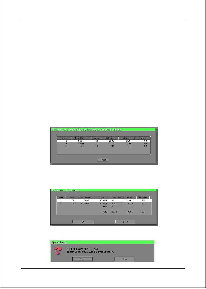
Disk To Disk (Disk Cloning)
1. Select the location of the Source drive.
2. Select the location of the Destination drive.
3. When cloning a disk or restoring the backup, set the required partition size as
shown in the following figure.
4. Click OK to display the following confirmation screen. Select Yes to start.
B-2
Page 61

Appendix
Disk To Image (Disk Backup)
1. Select the location of the Source drive.
2. Select the location for storing the backup file.
3. Click OK to display the following confirmation screen. Select Yes to start.
Disk From Image (Restore Backup)
1. Select the Restoring file.
B-3
Page 62

Appendix
2. Select the Destination drive of the disk to be restored.
3. When restoring disk backup, set the required partition size as shown in the
following figure.
4. Click OK to display the following confirmation screen. Select Yes to start.
Partition
B-4
Page 63

Appendix
There are 3 partition functions:
1. Partition To Partition (partition cloning)
2. Partition To Image (partition backup)
3. Partition From Image (restore partition)
Partition To Partition (Partition Cloning)
The basic unit for partition cloning is a “partition”. Refer to “disk cloning” for the
operating method.
Partition To Image (Partition Backup)
1. Select the disk to be backed up.
2. Select the first partition to be backed up. This is usually where the operating
system and programs are stored.
3. Select the path and file name to store the backup file.
B-5
Page 64

Appendix
4. Is the file compressed? There are 3 options:
(1) No: do not compress data during backup
(2) Fast: Small volume compression
(3) High: high ratio compression. File can be compressed to its minimum, but
requiring longer execution time.
5. Select Yes to start performing backup.
Partition From Image (Restore Partition)
1. Select the backup file to be restored.
2. Select the source partition.
B-6
Page 65

3. Select the disk to be restored.
4. Select the partition to be restored.
5. Select Yes to start restoring.
Appendix
Check
This function is to check possible error caused by defective FAT or
track during backup or restoring.
B-7
Page 66

Appendix
How to Reinstall Windows in 2 Minutes
This chapter guides you how to setup your computer properly and, if
necessary, reinstall Windows in 2 minutes. Ghost provides different
methods to complete this task. The following two sections explain how to
create an emergency Recover Floppy and Recover CD:
Emergency Recover Floppy
Divide a hard disk into two partitions. The first partition is to store the
operating system and application programs. The second partition is to back
up the operating system and data. The size of the partition can be
determined according to the backup requirements. For example, the
Windows operating system needs 200MB of hard disk space, Plus
complete Office programs require 360MB. The remaining space can be
used to store data.
After installing Windows, use Ghost to create a backup area for the system
and to store the file (Image file) in drive D. The file is named Original.gho.
Then, create a recover floppy disk containing:
Bootable files (Command.com, Io.sys, and MSDOS.SYS )
Config.sys (configuration setup file)
Autoexec.bat (auto-execution batch file)
Ghost.exe (Ghost execution file)
There are two ways to create the content of the recover floppy for
restoring:
(1)To load Windows automatically after booting, store the Autoexec.
bat file with a command line:
Ghost.exe clone, mode=pload, src=d:\original.gho:2,dst=1:1 -fx -sure -rb
Command Description: Runs the restore function automatically with
the Image File. Stored in drive D. After execution, it will exit Ghost
and boots the system.
Refer to the [Introducing Ghosts Functions] for details.
B-8
Page 67

Appendix
(2) After booting, the screen displays the Menu. Select Backup or Restore:
Since the user may install other applications in the future, he/she may
alter Autoexec.bat file to back up or restore the user-defined Image
file as follows:
BackupBackup
Backup
BackupBackup
Back up Windows and application programs as a file (Recent.
gho). Command is:
Ghost –clone,mode=pdump,src=1:1,dst=d:\Recent.gho -fx -
sure -rb
RestoreRestore
Restore
RestoreRestore
Restore types include [General Windows] and [Windows and
Application Programs]. If you select [General Windows],
the system is restored to the general Windows operation
condition. The command is:
Ghost.exe -clone,mode=pload,src=d:\Original.gho,dst=1:1 -fx
-sure -rb
If you select [Windows and Application Programs], the latest
backup file (Recent.gho) is restored, skipping the installation
and setup of application programs.
For description of related parameters, refer to [Introducing Ghosts
Functions].
For more information about menu design, refer to Config.sys and
Autoexec.bat under /Menu in the CD. You can also create a backup CD
containing Ghost.exe and these two files.
B-9
Page 68

Appendix
Recover CD
The following is a simple guide to create a recover CD:
1. First, create a recover floppy disk contains the following with any copy
program such as “Easy CD Create” (Note 2) :
Bootable files (Command.com and Io.sys and MSDOS.SYS)
Config.sys (Configuration setup file)
Autoexec.bat (Auto-execution batch file)
Mscdex.exe (CD-Rom execution file)
Ghost.exe (Ghost execution file)
Oakcdrom.sys (ATAPI CD-ROM compatible driver)
The content of Config.sys is:
DEVICE=Oakcdrom.sys /d:idecd001
The content of Autoexec.bat includes:
MSCDEX.EXE /D:IDECD001 /L:Z
Ghost.exe clone,mode=load,src=z:\original.gho,dst=1 -sure -rb
2. Write the backup image file (original.gho) of the entire hard disk or partition
into the recover CD. Use the Recover CD to boot up the system and restore
the backup files automatically.
For description of related parameters, refer to [Introducing Ghosts Functions].
Note: For more details about copy the creation program and method to create a
recover CD, please refer to the releated software and its associated operating
manual.
Note: Ghost may be executed in interactive or in batch mode. Most of the Ghost
switches are used to assist in batch mode operation. To list switches, type
ghost.exe -h.
B-10
 Loading...