

Page 1

2121
21
2121
Electronic Emission NoticesElectronic Emission Notices
Electronic Emission Notices
Electronic Emission NoticesElectronic Emission Notices
Federal Communications Commission (FCC) StatementFederal Communications Commission (FCC) Statement
Federal Communications Commission (FCC) Statement
Federal Communications Commission (FCC) StatementFederal Communications Commission (FCC) Statement
This equipment has been tested and found to comply with the limits for a Class B digital
device, pursuant to Part 15 of FCC Rules. These limits are designed to provide reasonable
protection against harmful interference in a residential installation. This equipment
generates, uses and can radiate radio frequency energy and, if not installed and used in
accordance with instructions contained in this manual, may cause harmful interference
to radio and television communications. However, there is no guarantee that interference
will not occur in a particular installation.
If this equipment does cause harmful interference to radio or television reception, which
can be determined by turning the equipment off and on, the user is encouraged to try to
correct the interference by one or more of the following measures:
- REORIENT OR RELOCATE THE RECEIVING ANTENNA
- INCREASE THE SEPARATION BETWEEN THE EQUIPMENT AND THE RECEIVER
- CONNECT THE EQUIPMENT INTO AN OUTLET ON A CIRCUIT DIFFERENT FROM
THAT OF THE RECEIVER
- CONSULT THE DEALER OR AN EXPERIENCED AUDIO/TELEVISION TECHNICIAN
NOTE: Connecting this device to peripheral devices that do not comply with Class B
requirements, or using an unshielded peripheral data cable, could also result in
harmful interference to radio or television reception.
The user is cautioned that any changes or modifications not expressly approved
by the party responsible for compliance could void the user’s authority to operate
this equipment.
To ensure that the use of this product does not contribute to interference, it is
necessary to use shielded I/O cables.
CopyrightCopyright
Copyright
CopyrightCopyright
This manual is copyrighted with all rights reserved. No portion of this manual may be
copied or reproduced by any means.
While every precaution has been taken in the preparation of this manual, no responsibility
for errors or omissions is assumed. Neither is any liability assumed for damages resulting
from the use of the information contained herein.
TrademarksTrademarks
Trademarks
TrademarksTrademarks
All brand names, logos and registered trademarks mentioned are property of their
respective owners.
Page 2

2222
22
2222
TT
able of Contentsable of Contents
T
able of Contents
TT
able of Contentsable of Contents
HARDWARE CONFIGURATIONHARDWARE CONFIGURATION
HARDWARE CONFIGURATION
HARDWARE CONFIGURATIONHARDWARE CONFIGURATION
Key Features ............................................................................................... 24
MOTHERBOARD LAYOUTMOTHERBOARD LAYOUT
MOTHERBOARD LAYOUT
MOTHERBOARD LAYOUTMOTHERBOARD LAYOUT
REAR PREAR P
REAR P
REAR PREAR P
AUDIO CONFIGURATIONAUDIO CONFIGURATION
AUDIO CONFIGURATION
AUDIO CONFIGURATIONAUDIO CONFIGURATION
SPEAKER CONFIGURATIONSPEAKER CONFIGURATION
SPEAKER CONFIGURATION
SPEAKER CONFIGURATIONSPEAKER CONFIGURATION
JAJA
JA
JAJA
JUMPER SETTING ............................................................................ 38
CPU Speed Selection ................................................................................. 38
JBAT1 - CMOS Clear ................................................................................... 38
JP6-IEEE1394 Function Selection .............................................................. 38
CONNECTORSCONNECTORS
CONNECTORS
CONNECTORSCONNECTORS
Floppy Disk Drive Connector:CN3 .............................................................. 39
Hard Disk Connectors:CN1&CN2 .............................................................. 39
Serial ATA Hard Disk Connectors:SATA1&SATA2........................................ 40
USB Connectors :USB1/USB2/USB3 ......................................................... 42
Fan Power Connectors:FAN1/FAN2/WOL ................................................... 43
AUX-IN Connector:AUX1 ............................................................................. 44
CD-IN Connector:CDS1 .............................................................................. 44
S-Bracket (SPDIF)/LEN/LFE/Surround Output Connector:
CN9(optional) .............................................................................................. 45
Front Panel Audio Header:CN21 ................................................................ 47
IEEE1394 Connectors:IEEE1&IEEE2 ......................................................... 48
Front Panel Header:FP1 ............................................................................. 50
ANELANEL
........................................................................................................................................................................
ANEL
....................................................................................
ANELANEL
........................................................................................................................................................................
Method 1: 4/6 Surround audio output of back panel only ...................... 30
Method 2: Using S-Bracket connectors ................................................. 32
CKCK
--
SENSING INSTRUCTIONSENSING INSTRUCTION
CK
-
SENSING INSTRUCTION
CKCK
--
SENSING INSTRUCTIONSENSING INSTRUCTION
..................................................................................................................................................................
................................................................................. 39
..................................................................................................................................................................
..............................................................................................................
.......................................................
..............................................................................................................
................................................................................................................................
................................................................
................................................................................................................................
................................................................................................................................
................................................................
................................................................................................................................
........................................................................................................................
............................................................
........................................................................................................................
................................................................................................................
........................................................
................................................................................................................
2424
24
2424
2727
27
2727
2828
28
2828
3030
30
3030
3030
30
3030
3535
35
3535
SLOTSSLOTS
SLOTS
SLOTSSLOTS
CPU INSTALLATIONCPU INSTALLATION
CPU INSTALLATION
CPU INSTALLATIONCPU INSTALLATION
HARDWARE SETUPHARDWARE SETUP
HARDWARE SETUP
HARDWARE SETUPHARDWARE SETUP
To Install DDR DIMMs ................................................................................. 54
Technical Reference Booklet
............................................................................................................................................................................................
..............................................................................................
............................................................................................................................................................................................
................................................................................................................................................
........................................................................
................................................................................................................................................
..................................................................................................................................................
.........................................................................
..................................................................................................................................................
5151
51
5151
5252
52
5252
5454
54
5454
Page 3

2323
23
2323
BIOS SETUPBIOS SETUP
BIOS SETUP
BIOS SETUPBIOS SETUP
Starting Setup .............................................................................................. 55
Main Menu ................................................................................................... 56
Standard CMOS Features ........................................................................... 57
Advanced BIOS Features ............................................................................ 58
Advanced Chipset Features ........................................................................ 58
Integrated Peripherals ................................................................................ 58
Power Management Setup .......................................................................... 58
PNP/PCI Configurations ............................................................................. 58
PC Health Status ......................................................................................... 58
Frequency/Voltage Control .......................................................................... 59
Set Supervisor/User Password .................................................................. 59
Flash Update Procedure ............................................................................. 60
VT8237 SATA RAID USER MANUALVT8237 SATA RAID USER MANUAL
VT8237 SATA RAID USER MANUAL
VT8237 SATA RAID USER MANUALVT8237 SATA RAID USER MANUAL
Enter BIOS Configuration Utility ............................................................. 61
Create Disk Array ................................................................................... 62
Delete Disk Array ................................................................................... 64
Select Boot Array .................................................................................... 64
Duplicate Critical RAID 1 Array .............................................................. 65
Rebuild Broken RAID 1 Array ................................................................. 66
DRIVER AND RAID SOFTWARE INSTALLATIONDRIVER AND RAID SOFTWARE INSTALLATION
DRIVER AND RAID SOFTWARE INSTALLATION
DRIVER AND RAID SOFTWARE INSTALLATIONDRIVER AND RAID SOFTWARE INSTALLATION
Microsoft Windows Driver Installation ................................................... 68
..........................................................................................................................................................................
.....................................................................................
..........................................................................................................................................................................
..........................................................................................
.............................................
..........................................................................................
........................................................
............................
........................................................
5555
55
5555
6161
61
6161
6868
68
6868
INSTALL OPERATING SYSTEM INTO SATA HDD OF VT8237INSTALL OPERATING SYSTEM INTO SATA HDD OF VT8237
INSTALL OPERATING SYSTEM INTO SATA HDD OF VT8237
INSTALL OPERATING SYSTEM INTO SATA HDD OF VT8237INSTALL OPERATING SYSTEM INTO SATA HDD OF VT8237
Install Windows 98SE or Me .................................................................. 70
Install Windows NT4.0,2000,XP ............................................................ 70
APPENDIXAPPENDIX
APPENDIX
APPENDIXAPPENDIX
..............................................................................................................................................................................
.......................................................................................
..............................................................................................................................................................................
............
......
............
7070
70
7070
7171
71
7171
Page 4

2424
24
2424
HARDHARD
HARD
HARDHARD
Key Key
Key
Key Key
ChipsetChipset
Chipset
ChipsetChipset
ProcessorProcessor
Processor
ProcessorProcessor
VRM 9.0(VVRM 9.0(V
VRM 9.0(V
VRM 9.0(VVRM 9.0(V
System MemorySystem Memory
System Memory
System MemorySystem Memory
System BIOSSystem BIOS
System BIOS
System BIOSSystem BIOS
WW
ARE CONFIGURAARE CONFIGURA
W
ARE CONFIGURA
WW
ARE CONFIGURAARE CONFIGURA
FeaturesFeatures
Features
FeaturesFeatures
• VIA K8T800/K8M800+VT8237 chipset.
• Support for AMDTM K8/ClawHammerTM Processor.
• Supports AMD AthlonTM 64 processor.
• Processor interface via HypertransportTM bus.
• Flexible motherboard design with on board VRM 9.0, easy to upgrade
• A total of two 184-pin DDR SDRAM sockets.
• Supports DDR400/DDR333/DDR266 SDRAM.
• DIMM sizes from 64 Mbytes to 2Gbyte.
• 2.5V DRAM interface for DDR SDRAM.
• PnP, APM, ATAPI and Windows® 98/2000/XP.
• Full support of ACPI & DMI.
• Auto detects and supports LBA harddisks with capacities over 160GB.
• Easy to upgrade BIOS by end-user.
: :
:
: :
oltage Roltage R
oltage R
oltage Roltage R
with future processors.
egulator Modules) On boardegulator Modules) On board
egulator Modules) On board
egulator Modules) On boardegulator Modules) On board
TIONTION
TION
TIONTION
On-board VGA On-board VGA
On-board VGA
On-board VGA On-board VGA
• 8/16/32/64 MB frame buffers using system memory.
• Internal AGP 8x equivalent performance.
• Graphics engine clock up to 200 MHz decoupled from memory clock.
• High quality DVD video playback.
• 128-bit 2D graphics engine.
• 128-bit 3D graphics engine.
Technical Reference Booklet
(only for K8M800)(only for K8M800)
(only for K8M800)
(only for K8M800)(only for K8M800)
Page 5

On-board I/OOn-board I/O
On-board I/O
On-board I/OOn-board I/O
• On board two PCI fast IDE ports supporting up to 4 ATA, ATA2 , Ultra
ATA33/ 66/100/133 IDE HDDs, CD-ROMs, ZIP drives and LS-120
drives as boot drive.
• One ECP/EPP parallel port.
• Two 16550 Compatible UART serial ports.(One port via a header)
• One floppy port supports two FDD of 360KB, 720KB, 1.2MB , 1.44MB
and 2.88MB capacity.
• Eight USB2.0 ports.
• PS/2 keyboard connector.
• PS/2 mouse is supported.
• One Front Panel Sound Connector.
• Infrared (IrDA) is supported via a header.
Expanded USB SupportExpanded USB Support
Expanded USB Support
Expanded USB SupportExpanded USB Support
• Includes 4 UHCI host controllers,increasing the number of external
ports to eight.
• Includes 1 EHCI USB2.0 Host Controller that supports eight ports
(Bandwidth shared between eight ports).
Full Featured Accelerated Graphics Port (AGP)Full Featured Accelerated Graphics Port (AGP)
Full Featured Accelerated Graphics Port (AGP)
Full Featured Accelerated Graphics Port (AGP)Full Featured Accelerated Graphics Port (AGP)
• Supports AGP3.0 including 4X/8X AGP card.
• AGP 1.5V connector support only.
• High priority access support.
2525
25
2525
Plug-and-PlayPlug-and-Play
Plug-and-Play
Plug-and-PlayPlug-and-Play
• Supports Plug and Play specification 1.1.
• Plug and Play for Windows® 98, Windows® 2000 as well
as Windows® XP.
• Fully steerable PCI interrupts.
On-board AC97 Sound(optional)On-board AC97 Sound(optional)
On-board AC97 Sound(optional)
On-board AC97 Sound(optional)On-board AC97 Sound(optional)
• Integrated AC97 controller with standard AC97 Codec.
• Direct Sound and Sound Blaster compatible.
• Full-Duplex 16-bit record and play back.
• PnP and APM 1.2 support.
• Windows® 98/2000/XP drivers ready.
• Line-in, Line-out, Mic-in and MIDI/Game port.
• Supports ALC650/655 AC97 Code for six sound channel
output (optional).
Hardware Configuration
Page 6
2626
26
2626
Integrated serial ATA/RAID ControllerIntegrated serial ATA/RAID Controller
Integrated serial ATA/RAID Controller
Integrated serial ATA/RAID ControllerIntegrated serial ATA/RAID Controller
• Independent DMA operation on two ports.
• Data transfer rate 150Mb/s.
• SATA devices can be configured in multiple RAID configurationssupports RAID Level0,RAID Level1 and JBOD.
On-board VT6103 LAN (optional)On-board VT6103 LAN (optional)
On-board VT6103 LAN (optional)
On-board VT6103 LAN (optional)On-board VT6103 LAN (optional)
• High performance PCI master interface with scatter / gather and
bursting capability.
• Standard MII interface to external PHYceiver.
• 10/100MHz full and half duplex operation.
Power ManagementPower Management
Power Management
Power ManagementPower Management
• Supports SMM, APM and ACPI.
• Break switch for instant suspend/resume on system operations.
• Energy star “Green PC” compliant.
• Hardware monitoring circuit is supported, provide voltage,
temperature, fan speed, etc. monitoring (optional).
• WOL (Wake-On-Lan) header support.
• Supports suspend-to-RAM(STR)(optional).
On-board IEEE1394(optional)On-board IEEE1394(optional)
On-board IEEE1394(optional)
On-board IEEE1394(optional)On-board IEEE1394(optional)
• Compliant with 1394 open HCI specifications v1.0 and v1.1.
• Integrated 400Mbit 2 port PHY.
Expansion SlotsExpansion Slots
Expansion Slots
Expansion SlotsExpansion Slots
• 1 AGP slot (support AGP 3.0-8X).
• 5 PCI bus master slots - ver. 2.1 compliant.
Static electricity can harm delicate components of the motherboard.
To prevent damage caused by static electricity, discharge the static
electricity from your body before you touch any of the computers
electronic components.
Technical Reference Booklet
Page 7
2727
27
2727
Motherboard Layout (35-Motherboard Layout (35-
Motherboard Layout (35-
Motherboard Layout (35-Motherboard Layout (35-
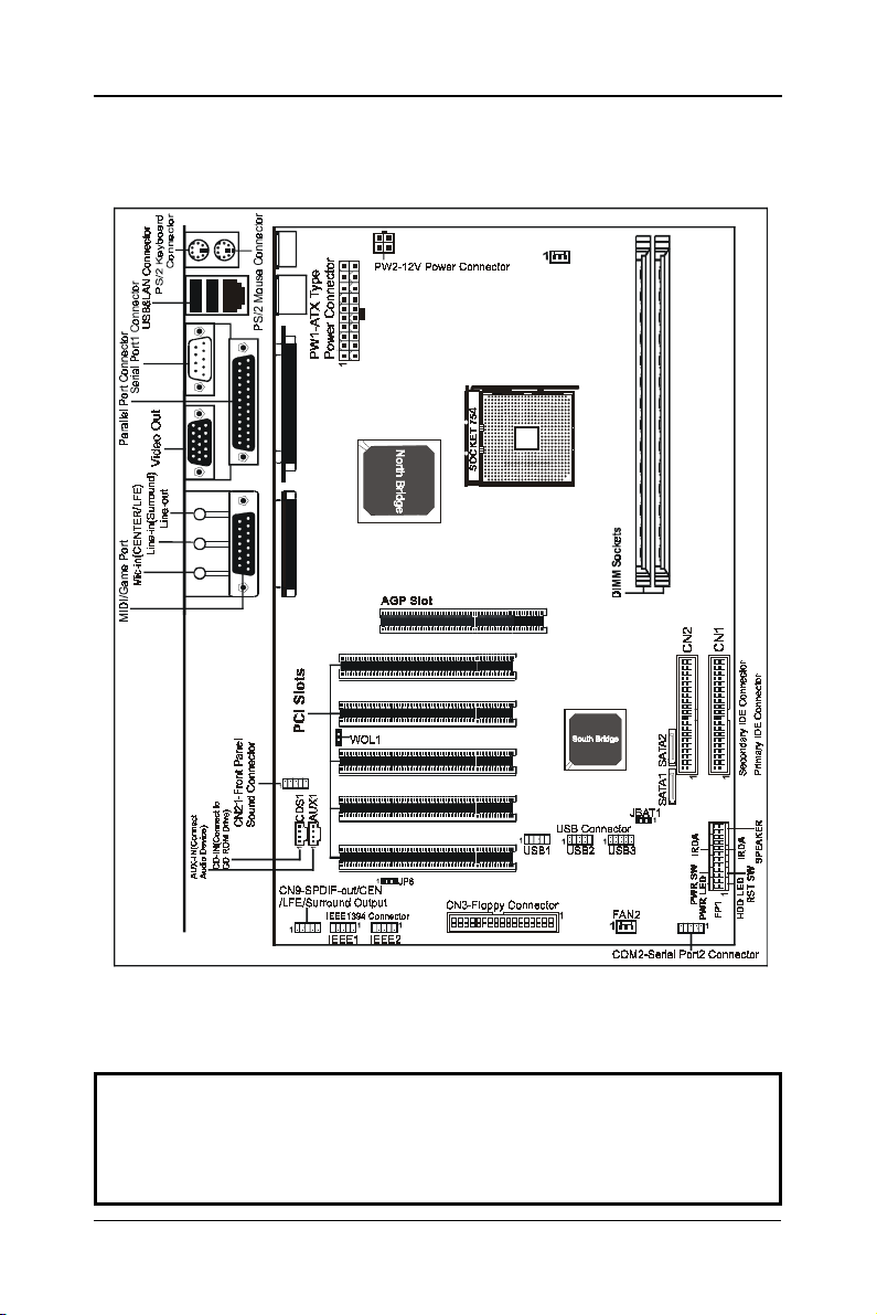
The following diagrams show the relative positions of the jumpers, connectors, major
components and memory banks on the motherboard.
AA14-AA14-
AA14-
AA14-AA14-
X0-X0-
X0-
X0-X0-
XX)XX)
XX)
XX)XX)
FAN1
# The LAN ,Video Out, IEEE1394, CN9 and JP6 Connectors are optional.
# The ALC650/655 embeds an internal analog switch (by driver software) to
share LINE input with Surround output, and share MIC input with CENTER/LFE
output.
NOTE
1) Be sure to check the cable orientation in order to match the colored strip to the pin
1 end of the connector.
2) When you start up the system, please wait for 5 seconds after you power on AC.
3) It is not recommended to add a metal spacer plate on the back of the Socket754.
Otherwise, some components will be short and damaged.
Motherboard layout
Page 8
2828
28
2828
Rear PanelRear Panel
Rear Panel
Rear PanelRear Panel
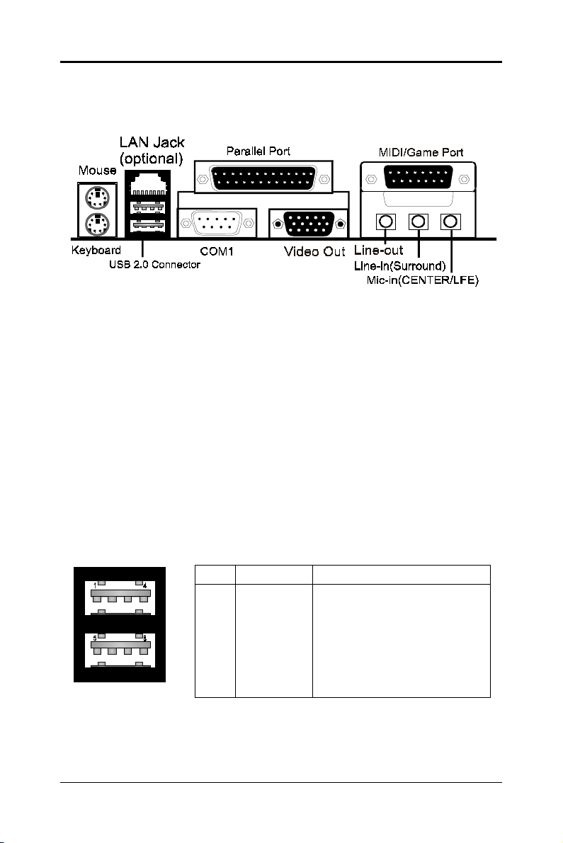
The back panel provides the following connectors:
Mouse ConnectorMouse Connector
Mouse Connector
Mouse ConnectorMouse Connector
The mainboard provides a standard PS/2
attaching a PS/2
®
mouse.You can plug a PS/2® mouse directly into this
®
mouse mini DIN connector for
connector.
Keyboard ConnectorKeyboard Connector
Keyboard Connector
Keyboard ConnectorKeyboard Connector
The mainboard provides a standard PS/2
for attaching a PS/2
®
keyboard.You can plug a PS/2® keyboard directly into
®
keyboard mini DIN connector
this connector.
USB 2.0 ConnectorUSB 2.0 Connector
USB 2.0 Connector
USB 2.0 ConnectorUSB 2.0 Connector
The mainboard provides a UHCI (Universal Host Controller Interface)
Universal Serial Bus root for attaching USB devices such as keyboard, mouse
or other USB-compatible devices.You can plug the USB device directly into
the connector.
Technical Reference Booklet
USB 2.0 Connector DescriptionUSB 2.0 Connector
PIN SIGNAL DESCRIPTION
1 VCC +5V/5VSB (optional)
2 -Data 0 Negative Data Channel 0
3 +Data0 Positive Data Channel 0
4 GND Ground
5 VCC +5V/5VSB (optional)
6 -Data 1 Negative Data Channel 1
7 +Data 1 Positive Data Channel 1
8 GND Ground
Page 9

2929
29
2929
Serial Port Connectors: COM1Serial Port Connectors: COM1
Serial Port Connectors: COM1
Serial Port Connectors: COM1Serial Port Connectors: COM1
The Port is 16550A high speed communication ports that send/receive
16bytes FIFOs. You can attach a serial mouse or other serial devices directly
to the connectors.
Video Out Connector (Optional)Video Out Connector (Optional)
Video Out Connector (Optional)
Video Out Connector (Optional)Video Out Connector (Optional)
The mainboard provides a Video out port to connect a 15-pin analog
video monitor.
LAN Jack (Optional)LAN Jack (Optional)
LAN Jack (Optional)
LAN Jack (Optional)LAN Jack (Optional)
The mainboard provides one standard RJ-45 jack for connection to Local
Area Network(LAN).You can connect a network cable to the LAN jack.
Parallel Port Connector:LPT1Parallel Port Connector:LPT1
Parallel Port Connector:LPT1
Parallel Port Connector:LPT1Parallel Port Connector:LPT1
The mainboard provides a 25-pin female centronic connector as LPT. A
parallel port is a standard printer port that supports Enhanced Parallel Port
(EPP) and Extended Capabilities Parallel Port (ECP) mode.
MIDI/Game Port (optional)MIDI/Game Port (optional)
MIDI/Game Port (optional)
MIDI/Game Port (optional)MIDI/Game Port (optional)
The mainboard provides the game port to connect a joystick or a MIDI
device.
Audio Port ConnectorAudio Port Connector
Audio Port Connector
Audio Port ConnectorAudio Port Connector
Line-Out is a connector for Speakers or Headphones. Line In is used for
external CD player, Tape player, or other audio devices. Mic In is a connector
for microphones. The ALC650/655 embeds an internal analog switch (by driver
software) to share LINE input with Surround output, and share MIC input with
CENTER/LFE output.
The ALC655 embeds the jack sensing function.When you plug an audio
device into the corresponding connector, the system will show you what you
pluged into the motherboard.
Rear Panel
Page 10
3030
30
3030
Audio ConfigurationAudio Configuration
Audio Configuration
Audio ConfigurationAudio Configuration
After installing the audio driver, you can select 4/6 channel surround
audio output in software utility and then connect surround speakers to
appropriate audio ports.
There are two ways to obtain 4/6 channel surround audio output:
1. 4/6 surround audio output of back panel only. All surround speaker
connect to audio connector.
2. S-Bracket (optional cable). You have installed S-Bracket into the
computer, and then connect two front speakers to back panel’s
“Line-out” port, and the rest of speakers to S-Bracket. Detail connection
is refer to Page 46.
SpeakSpeak
Speak
SpeakSpeak
er Configurationer Configuration
er Configuration
er Configurationer Configuration
Method 1: 4/6 Surround audio output of back panel only.
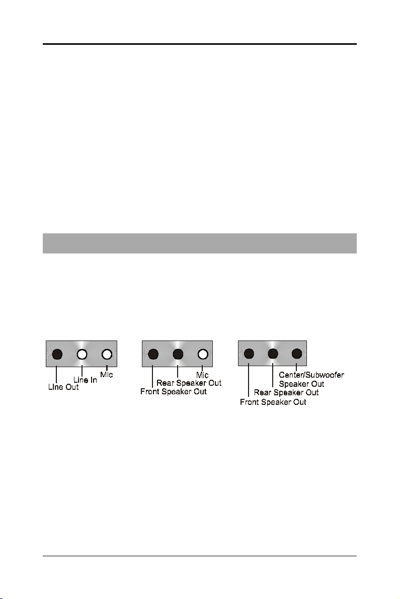
After installing the audio drivers, you can attach the speakers for 2-/4-/6channel audio output. Always connect the speakers to the LINE OUT
connectors. Different connector configurations for 2-/4-/6-channel
operations are listed below:
2-Channel
In 2-channel configuration,
Line Out, Line In and MIC
functions all exist.
4-Channel 6-Channel
When set to 4-channel
configuration, Line In
is replaced by Rear
Speaker Out. Line in
function does not exist.
When set to 6-channel
configuration, Line In
is replaced by Rear
Speaker Out. Mic is
replaced by Center/
Subwoofer Speaker Out.
Line in and Mic do not
exist function.
Technical Reference Booklet
Page 11

3131
31
3131
In utility, double click “AC97 Audio configuration” icon from the
window tray on the right bottom.
Then the “AC97 Audio Configuration” will appear. Click on the Speaker
Configuration tab to select the audio mode.
A. When you choose 4-channel mode for 4 speaker output, the selected item
is showed as below (Figure1)
(Figure1)
Software Configuration
Page 12

3232
32
3232
B. When you choose 6-channel mode for 5.1 speaker output, the selected
item is showed as below (Figure2)
(Figure2)
Method 2: Using S-BRACKET connectors:
S-Bracket (The S-Bracket is showed in page 46) is an optional accessory.
It gives access to analog and digital audio output by integrating both SPDIF
and analog LINE OUT connectors. To use the S-Bracket, you should select
correct setting in the software utility. For information about the setting, refer
to selecting 4- or 6- Channel Setting later in the section.
Connector configurations for 4- and 6- channel using S-Bracket are
described below:
Technical Reference Booklet
Page 13

4-Channel Analog Audio Output
Back Panel S-Bracket
+
(Front channels)
1
SPDIF jack (coaxial)
2
Rear Speaker Out
3
No function
Description:Description:
Description:
Description:Description:
Connect two speakers to back panel’s Line Out connector and two
speakers to one Line Out connector of S-Bracket. If you want to use
Line In function, please click the Rear Speaker Out button (showed
as below)
1
23
3333
33
3333
Software Configuration
Page 14

3434
34
3434
6-Channel Analog Audio Output
Back Panel S-Bracket
+
1
(Front channels)
1
SPDIF jack (coaxial)
2
Rear Speaker Out
3
Center and Subwoofer Out
Description:Description:
Description:
Description:Description:
Connect two speakers to back panel’s Line Out connector and four
speakers to both Line Out connectors of S-Bracket. If you want to use
Line In and MIC function at the same time, please click the Rear
Speaker Out and Center/Subwoofer Speaker Out buttons.
(showed as below)
23
Technical Reference Booklet
Page 15

3535
35
3535
JackJack
--
Jack
JackJack
Jack-Sensing provides audio connectors error-detection function.
Install Microsoft DirectX8.1 before to enable Jack-Sensing support
for Windows 98/98SE/2000/ME.
Jack-Sensing includes 2 parts:AUTO and MANUAL. Following is an
example for 2 channels (Windows XP):
Introduction of audio connectors
You may connect CDROM, Walkman or others audio input devices to Line In
jack. speakers, earphone or others output devices to Line Out jack. and
microphone to MIC In jack.
Sensing InstructionSensing Instruction
-
Sensing Instruction
--
Sensing InstructionSensing Instruction
Jack-sensing instruction
Page 16

3636
36
3636
Auto-detecting:
Please connect the devices to the right jacks as above. A window will appear
as below picture if you setup the devices properly.
If you set wrong with the connectors, the warning message will come out as
following picture.
Technical Reference Booklet
Page 17

Manual setting:
If the device picture shows different from what you set, please press
“Correction...” to set.
3737
37
3737
Manual setting
Page 18

3838
38
3838
Jumper SettingsJumper Settings
Jumper Settings
Jumper SettingsJumper Settings
This chapter explains how to configure the motherboard’s hardware. Before using your
computer, make sure all jumpers and DRAM modules are set correctly. Refer to this
chapter whenever in doubt.
JBAT1
JP6
1
CPU Speed SelectionCPU Speed Selection
CPU Speed Selection
CPU Speed SelectionCPU Speed Selection
In this motherboard, jumperless feature is implemented such that no jumper is required to
be set for different type of CPU installed.
1
Notice:
1. Be sure to save the CMOS setting when exit the CMOS.
2. If the CPU is frequency multiplier locked, no CPU speed change will be seen
even if the frequency multiplier setting in CMOS setup is changed.
JBAT1 - CMOS ClearJBAT1 - CMOS Clear
JBAT1 - CMOS Clear
JBAT1 - CMOS ClearJBAT1 - CMOS Clear
JBAT1 Selection
1-2* Normal*
2-3 CMOS Clear
JP6-On Board IEEE1394 Select (optional)JP6-On Board IEEE1394 Select (optional)
JP6-On Board IEEE1394 Select (optional)
JP6-On Board IEEE1394 Select (optional)JP6-On Board IEEE1394 Select (optional)
JP6 Function
1-2* IEEE1394 Enable*
2- 3 IEEE1394 Disable
Close Open * = Default setting.
Technical Reference Booklet
Page 19

3939
39
3939
ConnectorsConnectors
Connectors
ConnectorsConnectors
The mainboard provides connectors to connect to FDD, IDE HDD,
Serial ATA Hard Disk,USB devices, CPU/PWRFAN/WOL ,etc.
Floppy Disk Drive Connector:CN3
The mainboard provides a standard floppy disk drive connector that
supports 360K, 720K, 1.2M, 1.44M and 2.88M floppy disk types.
Hard Disk Connectors:CN1&CN2
The mainboard has a 32-bit Enhanced PCI IDE and Ultra DMA 33/66/100/
133controller that provides PIO mode 0~4, Bus Master, and Ultra DMA 33/66/
100/133function. You can connect up to four hard disk drives, CD-ROM, 120MB
Floppy (reserved for future BIOS) and other devices.
CN1 (Primary IDE Connector)
The first hard drive should always be connected to IDE1.IDE1 can connect
a Master and a Slave drive.You must configure second hard drive to Slave
mode by setting the jumper accordingly.
CN2 (Secondary IDE Connector)
IDE2 can also connect a Master and a Slave drive.
CN3
CN2
CN1
1
1
1
Connectors
Page 20

4040
40
4040
Serial ATA Hard Disk Connectors: SATA1&SATA2
The mainboard has 2 SATA connectors. The mainboard provides dual
high-speed Serial ATA interface ports, SATA1,SATA2 Each supports 1
generation serial ATA data rates of 150 MB/s. Both connectors are fully compliant
with Serial ATA 1.0 specifications. Each Serial ATA connector can connect to 1
hard disk device. Please refer to Serial ATA Raid manual for detail software
installation procedure.
st
SATA2
SASA
TT
A1&SAA1&SA
SA
T
A1&SA
SASA
TT
A1&SAA1&SA
PIN SIGNAL
1 GND
2 TXP
3 TXN
4 GND
5 RXN
6 RXP
7 GND
Technical Reference Booklet
TT
T
TT
A2A2
A2
A2A2
SATA1
Page 21

4141
41
4141
Serial ASerial A
Serial A
Serial ASerial A
Connect one end of the SATA cable to the mainboard, and connect another
end to the SATA Hard Disk.
TT
A CableA Cable
T
A Cable
TT
A CableA Cable
Please do not fold the serial ATA cable in a 90-degree angle, which
will cause the loss of data during the transmission.
Serial ASerial A
Serial A
Serial ASerial A
TT
A Hard Disk Devices PA Hard Disk Devices P
T
A Hard Disk Devices P
TT
A Hard Disk Devices PA Hard Disk Devices P
ower Cable(optional)ower Cable(optional)
ower Cable(optional)
ower Cable(optional)ower Cable(optional)
Connectors
Page 22

4242
42
4242
USB Connectors: USB1/USB2/USB3USB Connectors: USB1/USB2/USB3
USB Connectors: USB1/USB2/USB3
USB Connectors: USB1/USB2/USB3USB Connectors: USB1/USB2/USB3
This mainboard has USB ports. Some computer cases have a special
module that mounts USB ports at the front of the case. If you have this kind
of case, use auxiliary USB connector USB1/USB2/USB3 to connect the
front mounted ports to the mainboard.
USB1USB1
USB1
USB1USB1
22
2
22
11
1
11
PIN Assignment
1 VCC
2 VCC
3 USBP04 USBP15 USBP0+
6 USBP1+
7 GND
8 GND
9 KEY
10 OC#
Technical Reference Booklet
USB2USB2
USB2
USB2USB2
1010
10
1010
22
2
22
99
9
99
11
1
11
USB ConnectorUSB Connector
USB Connector
USB ConnectorUSB Connector
1010
10
1010
99
9
99
22
2
22
11
1
11
USB3USB3
USB3
USB3USB3
1010
10
1010
99
9
99
Page 23

4343
43
4343
Fan Power Connectors:FAN1&FAN2
The FAN1 (processor fan), FAN2 (system fan) support system cool-ing
fan with +12V.It supports three-pin head connector. When connecting the
wire to the connectors, always take note that the red wire is the positive and
should be connected to the +12V, the black wire is Ground and should be
connected to GND. If the mainboard has a System Hardware Monitor chipset
on-board, you must use a specially designed fan with speed sensor to take
advantage of the CPU fan control.
FAN1
1
WOL
1
FAN2
1
WOL: Wake On LAN
If you have installed a LAN card, use the cable provied with the card to plug
into the mainboard WOL connector. This enables ables the Wake On LAN
(WOL) feature. When your system is in a power-saving mode, any LAN signal
automatically resumes the system.You must enable this item using the Power
Mannagement page of the Setup Utility.
Connectors
Page 24

4444
44
4444
AUX-IN Connector:AUX1
The connector is for Audio Device.
CD-IN Connector:CDS1
The connector is for CD-ROM Drive.
CDS1 : CDS1CDS1 : CDS1
CDS1 : CDS1
CDS1 : CDS1CDS1 : CDS1
PIN Assignment
1 CD-L
2 GND
3 GND
4 CD-R
AUX1 : AUX1AUX1 : AUX1
AUX1 : AUX1
AUX1 : AUX1AUX1 : AUX1
PIN Assignment
1 AUX-L
2 GND
3 GND
4 AUX-R
CDS1
1
AUX1
1
Technical Reference Booklet
Page 25

4545
45
4545
S-Bracket(SPDIF)
/CEN/LFE/Surround Output/CEN/LFE/Surround Output
/CEN/LFE/Surround Output Connector:
/CEN/LFE/Surround Output/CEN/LFE/Surround Output
CN9 (optional)
The connector allows you to connect a S-Bracket for a Digital Interface
(SPDIF). The S-Bracket offers 1 SPDIF jacks for digital audio transmission
and 2 analog Line-Out jacks for other 4-channel audio output. So you can use
Line in, Mic in and 6 channel audio output features at the same time.
CN9
22
2
22
11
1
11
1010
10
1010
99
9
99
Connectors
Page 26

4646
46
4646
CN9-CN9-
SS
CN9-
CN9-CN9-
S-Bracket Cable (optional)S-Bracket Cable (optional)
S-Bracket Cable (optional)
S-Bracket Cable (optional)S-Bracket Cable (optional)
-Brack-Brack
S
-Brack
SS
-Brack-Brack
PIN SIGNAL DESCRIPTION
1 SOUT-L Audio left surrounding output
2 SOUT-R Audio right surrounding output
3 GND Ground
4 GND Ground
5 CET-OUT Audio center output
6 LFE-OUT Audio bass output
7 GND Ground
8 SPDIF S/PDIF input
9 (No Pin) Key
10 SPDFO S/PDIF output
etet
et
etet
Connect to CN9
Center and Subwoofer Out
Technical Reference Booklet
Rear Speaker Out
SPDIF jack (coaxial)
Page 27

Front Panel Audio Header: CN21Front Panel Audio Header: CN21
Front Panel Audio Header: CN21
Front Panel Audio Header: CN21Front Panel Audio Header: CN21
This mainboard supports front panel microphone and speaker out ports.
If your computer case has these ports,connect them to CN21.
CN21CN21
CN21
CN21CN21
22
2
22
11
1
11
CN21CN21
CN21
CN21CN21
PIN Assignment
1 MIC
2 GND
3 REF
4 POWER
5 Front Audio(R)
6 Rear Audio(R)
7 Reserved
8 Key(No pin)
9 Front Audio(L)
10 Rear Audio(L)
1010
10
1010
99
9
99
4747
47
4747
Note:Note:
Note:
Note:Note:
If you want to use “Front Audio” connector, you must remove 5-6,9-10 jumper.
In order to utilize the front audio header, your chassis must have front
audio connector. Also please make sure the pin assignment on the cable
is the same as the pin assignment on the MB header. To find out if the
chassis you are buying support front audio connector, please contract
your dealer.
Connectors
Page 28

4848
48
4848
IEEE 1394 Connectors: IEEE1&IEEE2 (optional)
The mainboard provides two 1394 pin headers that allow you to connect
IEEE 1394 ports.
IEEE1IEEE1
IEEE1
IEEE1IEEE1
99
9
99
1010
10
1010
Technical Reference Booklet
IEEE2IEEE2
IEEE2
IEEE2IEEE2
11
99
1
9
11
99
22
1010
2
10
22
1010
11
1
11
22
2
22
Page 29

IEEE1&IEEE2 Pin DefinitionIEEE1&IEEE2 Pin Definition
IEEE1&IEEE2 Pin Definition
IEEE1&IEEE2 Pin DefinitionIEEE1&IEEE2 Pin Definition
PIN SIGNAL
1TPA+
2TPA3 Ground
4 Ground
5 TPB+
6 TPB7 Cable power
8 Cable power
9 Key (no pin)
10 Ground
IEEE 1394 Cable (optional)IEEE 1394 Cable (optional)
IEEE 1394 Cable (optional)
IEEE 1394 Cable (optional)IEEE 1394 Cable (optional)
4949
49
4949
Connectors
Page 30

5050
50
5050
Front Panel Header: FP1Front Panel Header: FP1
Front Panel Header: FP1
Front Panel Header: FP1Front Panel Header: FP1
The mainboard provides one front panel connector for electrical connecti
-on to the front panel switches and LEDs.
Technical Reference Booklet
GND
NC
KEY
KEY
IRRX
GND
KEY
KEY
GND
PWR_SW
PW_LED-
PW_LED+
FP1FP1
FP1
FP1FP1
24 23
22 21
20
16
14
12
10
8
6
4
2
19
1718
15
13
11
9
7
5
3
1
VCC
GND
NC
SPEAKER
IRTX
VCC
NC
NC
RESET
GND
HDD_LED-
HDD_LED+
Page 31

SlotsSlots
Slots
SlotsSlots
The motherboard provides one AGP slot,five 32-bit PCI bus slots.
AGP SlotAGP Slot
AGP Slot
AGP SlotAGP Slot
PCI SlotsPCI Slots
PCI Slots
PCI SlotsPCI Slots
AGP (Accelerated Graphics Port) SlotAGP (Accelerated Graphics Port) Slot
AGP (Accelerated Graphics Port) Slot
AGP (Accelerated Graphics Port) SlotAGP (Accelerated Graphics Port) Slot
The AGP slot allows you to insert the AGP graphics card. AGP is an interface specification designed for the throughput demands of 3D graphics. It
introduces a 66MHz, 32-bit channel for the graphics controller.
5151
51
5151
PCI (Peripheral Component Interconnect) SlotsPCI (Peripheral Component Interconnect) Slots
PCI (Peripheral Component Interconnect) Slots
PCI (Peripheral Component Interconnect) SlotsPCI (Peripheral Component Interconnect) Slots
The PCI slots allow you to insert the expansion cards to meet your needs.
When adding or removing expansion cards, make sure that you unplug the
power supply first. Meanwhile,read the documentation for the expansion card
to make any necessary hardware or software settings for the expansion card,
such as jumpers, switches or BIOS configuration.
Slots
Page 32

5252
52
5252
CPU InstallationCPU Installation
CPU Installation
CPU InstallationCPU Installation
Please refer to the following steps to install the CPU.
1. Please turn off the power and unplug the power cord before installing the
CPU. Pull the lever sideways away from the socket. Make sure to raise the
lever up to a 90 degree angle.
2. Look for the gold arrow. The gold arrow should point towards the lever pivot.
The CPU can only fit in the correct orientation.
2. If the CPU is correctly installed, the pins should be completely embedded
into the socket and can not be seen. Please note that any violation of the
correct installation procedures may cause permanent damages to your
mainboard.
Technical Reference Booklet
 Loading...