

Page 1

VIA / JMicron RAID Installation Guide
1. Introduction to VIA / JMicron RAID Installation Guide ………………………………………………………………………. 3
2. VIA RAID Installation Guide ……………………………………………………………………………………………………. 3
2.1 VIA BIOS RAID Installation Guide …………………………………………………………………………………….. 3
2.1.1 Introduction of RAID ………………………………………………………………………………………………. 3
2.1.2 RAID Configuration Precautions ………………………………………………………………………………… 4
2.1.3 BIOS Configuration Utility ………………………………………………………………………………………… 5
2.1.3.1 Enter BIOS Configuration Utility ………………………………………………………………………….. 5
2.1.3.2 Create Disk Array ………………………………………………………………………………………….. 5
2.1.3.3 Delete Disk Array ………………………………………………………………………………………….. 7
2.1.3.4 Select Boot Array ………………………………………………………………………………………….. 8
2.2 VIA Windows RAID Installation Guide ………………………………………………………………………………… 8
2.2.1 Create RAID Array ………………………………………………………………………………………………… 9
2.2.2 Delete Disk Array ……………………………………………………………………………………………..…… 11
2.2.3 Check All Disks ……………………………………………………………………………………………………. 12
2.2.4 Verify Mirror Disk ………………………………………………………………………………………………….. 12
2.2.5 Synchronize Mirror Disk ………………………………………………………………………………………….. 13
2.2.6 Disk Error Detection ………………………………………………………………………………………………. 14
2.2.7 Duplicate Critical RAID 1 Array ………………………………………………………………………………….. 14
2.2.8 Rebuild Broken RAID 1 array ……………………………………………………………………………………. 15
1
Page 2

3. JMicron RAID Installation Guide ……………………………………………………………………………………………….. 17
3.1 JMicron BIOS RAID Installation Guide ………………………………………………………………………………… 17
3.1.1 BIOS Configuration Utility …………………………………………………………………………………………. 17
3.1.1.1 Enter BIOS Configuration Utility ……………………. ……………………………………………….. 17
3.1.1.2 Create RAID Disk Drive ……………………………………………………………………………….. 18
3.1.1.3 Delete RAID Disk Drive ……………………………………………………………………………….. 21
3.1.1.4 Revert HDDs to non-RAID ………………………………………………………………………….… 21
3.1.1.5 Solve Mirror Conflict …………………………………………………………………………………… 22
3.1.1.6 Rebuild Mirror Drive ……………………………………………………………………………………. 22
3.2 JMicron Windows RAID Installation Guide …………………………………………………………………………….. 23
3.2.1 Creating RAID ………………………………………………………………………………………………………. 23
3.2.2 Creating RAID from Existing Disk ………………………………………………………………………………… 25
3.2.3 Deleting RAID ……………………………………………………………………………………………………….. 26
3.2.4 Rebuilding RAID …………………………………………………………………………………………………….. 26
3.2.5 Auto-Resynching RAID ……………………………………………………………………………………………… 27
2
Page 3
1. Introduction to VIA / JMicron RAID Installation Guide
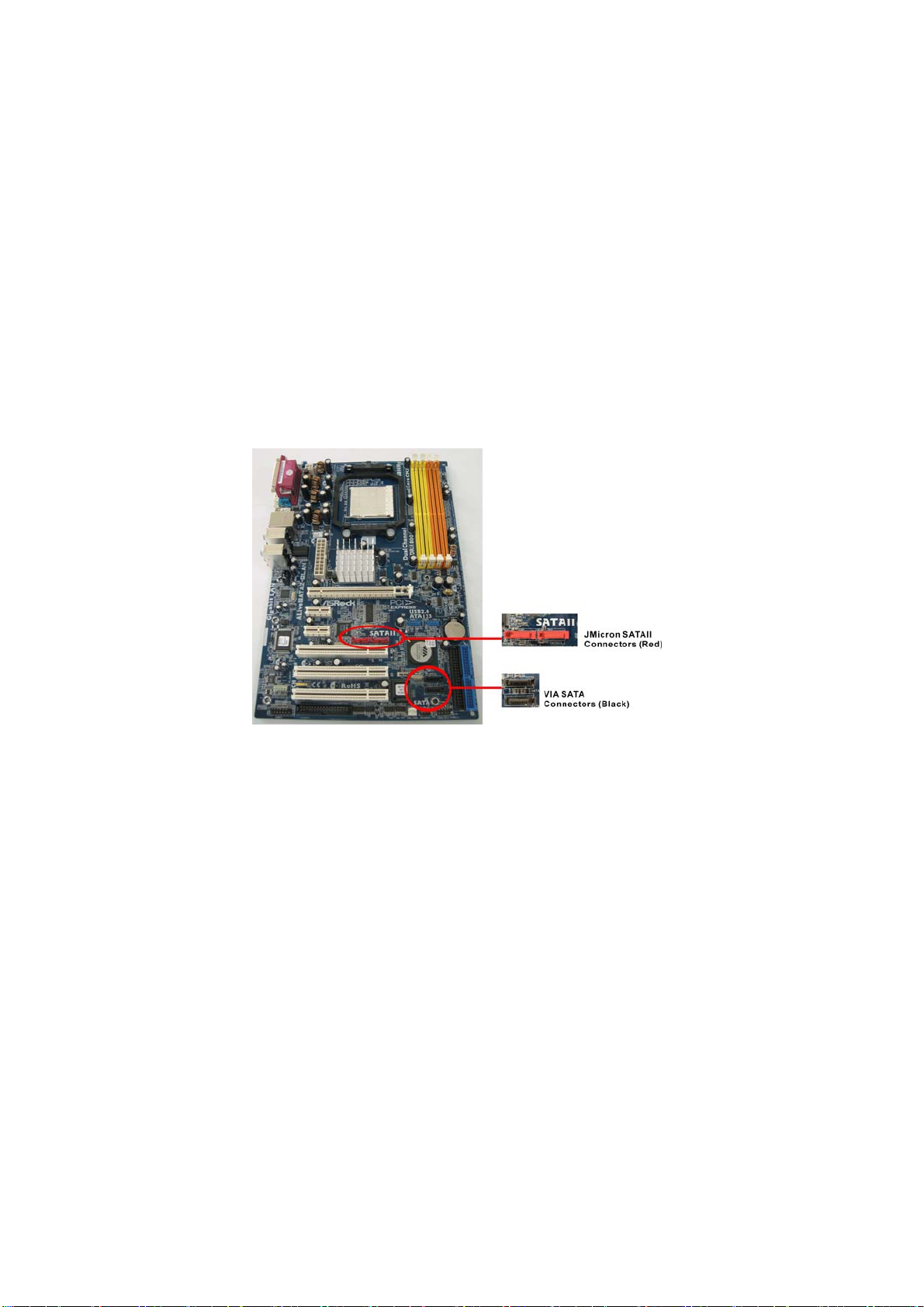
This motherboard is equipped with 2 SATA connectors supported by VIA VT8237A south bridge chipset, which support RAID (RAID 0, RAID 1,
JBOD) functions, and 2 SATAII connectors supported by JMicron JMB363 chipset, which support RAID (RAID 0, RAID 1, JBOD) functions. To
create RAID with two HDDs, please insert the two HDDs simultaneously to either VIA SATA connectors (black) or JMicron SATAII connectors
(red). If you insert two HDDs to VIA SATA connectors and plan to configure RAID functions, please refer to VIA RAID installation guide part,
including VIA BIOS/Windows RAID installation guide. If you insert two HDDs to JMicron SATAII connectors and plan to configure RAID functions,
please refer to JMicron RAID installation guide part, including JMicron BIOS/Windows RAID installation guide.
To configure RAID functions on this motherboard correctly, please read this installation guide and follow the installation procedures carefully. You
may refer to the motherboard layout below for SATA (black) and SATAII (red) connectors’ location before configuring RAID functions.
Please note that if you insert one HDD to SATA connector and the other HDD to SATAII connector, you are not allowed to create RAID.
2. VIA RAID Installation Guide
If you insert two HDDs to VIA SATA connectors and plan to configure RAID functions, please refer to VIA RAID installation guide part, including
VIA BIOS RAID installation guide and VIA Windows RAID installation guide.
2.1 VIA BIOS RAID Installation Guide
You are allowed to configure RAID functions under BIOS environment.
2.1.1 Introduction of RAID
3
Page 4

VIA VT8237A south bridge chipset integrates RAID controller supporting RAID 0, RAID 1, and JBOD functions with two independent SATA
channels. This section will introduce the basic knowledge of RAID.
RAID
The term “RAID” stands for “Redundant Array of Independent Disks”, which is a method combining two or more hard disk drives into one logical
unit. For optimal performance, please install identical drives of the same model and capacity when creating a RAID set.
RAID 0 (Data Striping)
RAID 0 is called data striping that optimizes two identical hard disk drives to read and write data in parallel, interleaved stacks. It will improve data
access and storage since it will double the data transfer rate of a single disk alone while the two hard disks perform the same work as a single
drive but at a sustained data transfer rate.
WARNING!
Although RAID 0 function can improve the access performance, it does not provide any fault tolerance. Hot-Plug any HDDs of the RAID 0 Disk will cause data
damage or data loss.
RAID 1 (Data Mirroring)
RAID 1 is called data mirroring that copies and maintains an identical image of data from one drive to a second drive. It provides data
protection and increases fault tolerance to the entire system since the disk array management software will direct all applications to the
surviving drive as it contains a complete copy of the data in the other drive if one drive fails.
JBOD (Spanning)
A spanning disk array is equal to the sum of all drives. Spanning stores data onto a drive until it is full then proceeds to store files onto the next
drive in the array. When any member disk fails, it will affect the entire array. JBOD is not really a RAID, and it does not support fault tolerance.
2.1. 2 RAID Configurations Precautions
Please use two new drives if you are creating a RAID 0 (striping) array for performance. It is recommended to use two SATA drives of the same
size. If you use two drives of different sizes, the smaller capacity hard disk will be the base storage size for each drive. For example, if one hard
disk has an 80GB storage capacity and the other hard disk has 60GB, the maximum storage capacity for the 80GB-drive becomes 60GB, and the
total storage capacity for this RAID 0 set is 120GB.
1. You may use two new drives, or use an existing drive and a new drive to
create a RAID 1 (mirroring) array for data protection (the new drive must be of the same size or larger than the existing drive). If you use two
drives of different sizes, the smaller capacity hard disk will be the base storage size. For example, if one hard disk has an 80GB storage
capacity and the other hard disk has 60GB, the maximum storage capacity for the RAID 1 set is 60GB.
2. Please verify the status of your hard disks before you set up your new RAID array.
4
Page 5
2.1.3 BIOS Configuration Utility
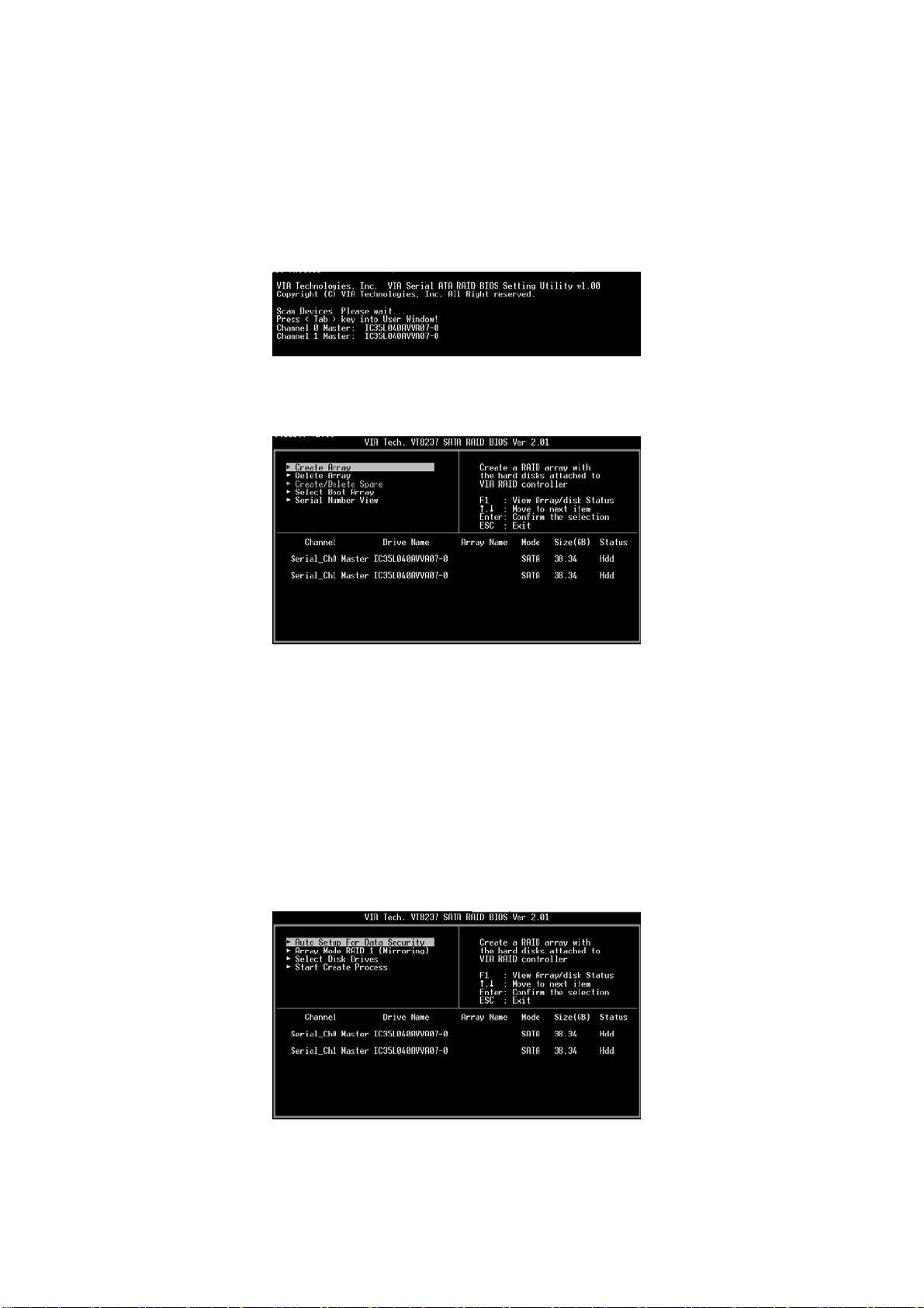
2.1.3.1 Enter BIOS Configuration Utility
After the system powers on, the following information will appear on the screen. Press ‘Tab’ key to enter BIOS configuration utility.
The main interface of BIOS configuration utility is as below:
2.1.3.2 Create Disk Array
1. Within the main interface, use the up and down arrow key to highlight the Create Array command and press <Enter> to call out the list of
creation steps.
2. Highlight the Array Mode and press <Enter>, then a list of array modes will appear. Just highlight the target array mode that you want to
create, and press <Enter> to confirm the selection.
5
Page 6
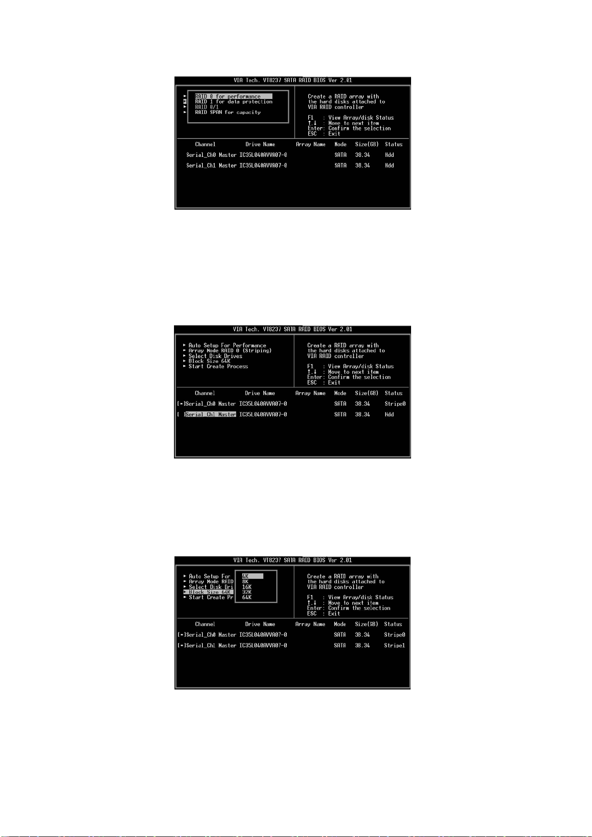
3. There are two methods to create a disk array. One method is “Auto Setup”, and another is “Select Disk Drives”. Select “Auto Setup” to
allow BIOS to select the disk drives and create array automatically. Select “Select Disk Drives” to let user select the array drives
manually. When using Select Disk Drives method, the channel column will be activated. Just highlight the target drives that you want to
use and press <Enter> to select them respectively. When all drives have been selected, press <Esc> to go back to the creation steps
menu.
Create RAID 0
If RAID 0 array is selected in step 2, user can also select a block size for the array. Use the arrow key to highlight the “Block Size” and press
<Enter>. Then the list of available block size will popup. The block size can be selected from 4K to 64K Bytes.
Use the arrow key to highlight the Start Create Process and press <Enter>, then a warning message will appear. Press Y to finish the creation, or
press N to cancel the creation. Please note that the content of the hard drive will be destroyed after array creation.
6
Page 7
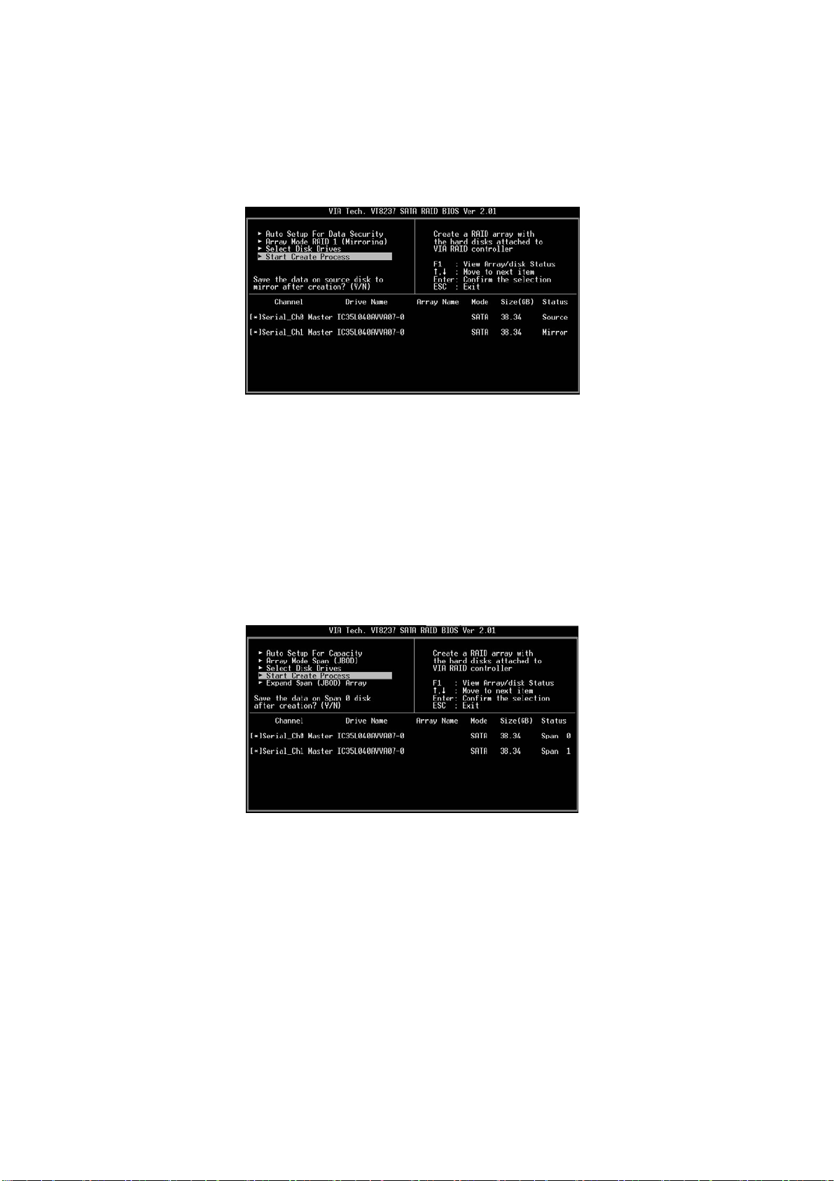
Create RAID 1
The data on disk drives will be destroyed if user uses “Auto Setup” to create RAID 1. But you can reserve the data on source drive if you use
“Select Disk Drives” to select the source and the mirror drive.
Press “y” to copy data of source to mirror drive. There is a limitation when using this feature. The capacity of mirror drive must be greater or equal
to the source drive; otherwise the RAID 1 can’t be created and a error message will appear: “Error: mirror’s size is smaller than source!!! Press
ESC return”. If user does not want to duplicate data, the data on the source and the mirror drive will be destroyed.
Create JBOD
The data on disk drives will be destroyed if user uses “Auto Setup” to create a JBOD. However, you can reserve the data on the first disk drive of
a JBOD array if you use “Select Disk Drives” to select disk drives
The data on the first disk drive will be reserved and the other disk drives in JBOD will be expanded behind the first disk drive and become free
space. Expand Span (JBOD) Array function is not available if VT8237A only supports 2 SATA ports.
2.1.3.3 Delete Disk Array
User can delete a specific RAID that has been created. Following are the steps to delete a created disk array.
1. Use arrow key to highlight Delete Array item in main menu interface, and
press <Enter>. The channel column will be activated.
2. Use arrow key to highlight the target disk drive and press <Enter>. A
7
Page 8
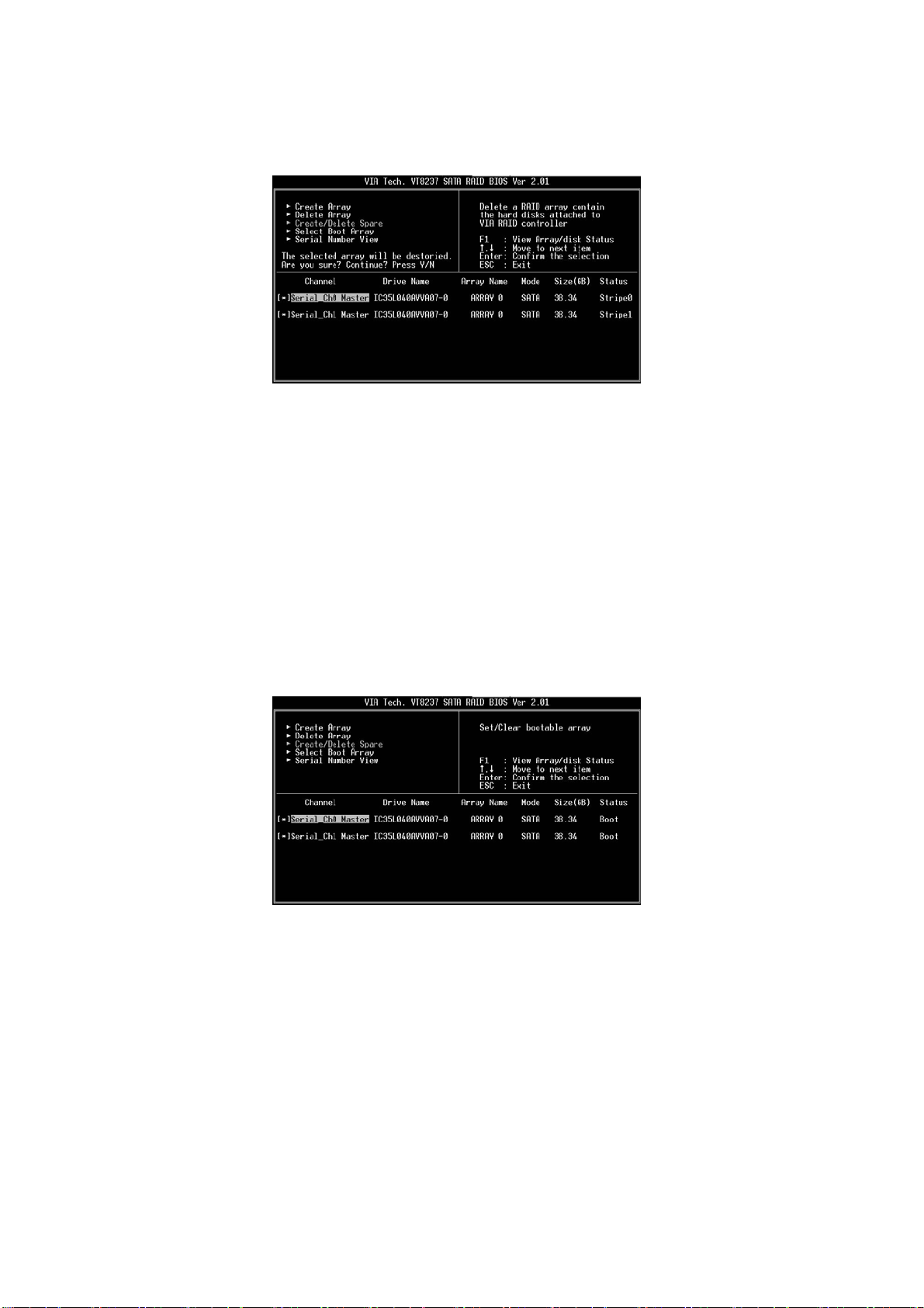
warning message will appear. Press Y to delete a specific array or press N to cancel.
Delete a disk array will destroy all the data on the disk array except RAID 1. When a RAID 1 is deleted, the data on these two hard disk drives will
be reserved and become two normal disks.
2.1.3.4 Select Boot Array
User can select a disk array as boot device if user wants to boot operating system from an array. Boot disk array may not be selected if user does
not boot the Operating System from the disk array. Use the arrow key to highlight the “Select Boot Disk” item then press <Enter>. The channel
column will be activated. Just use arrow key to highlight the target disk array then press <Enter>. If you select a disk array that has a boot mark
and press <Enter>, then its boot setting will be canceled.
2.2 VIA Windows RAID Installation Guide
You are allowed to configure RAID functions under Windows environment. The “RAID Software” is a Windows-based software utility with
graphical user interface and provides user an easy-operation tool to configure and manage disk drives or disk arrays connected to VT8237 SATA
controller.
8
Page 9
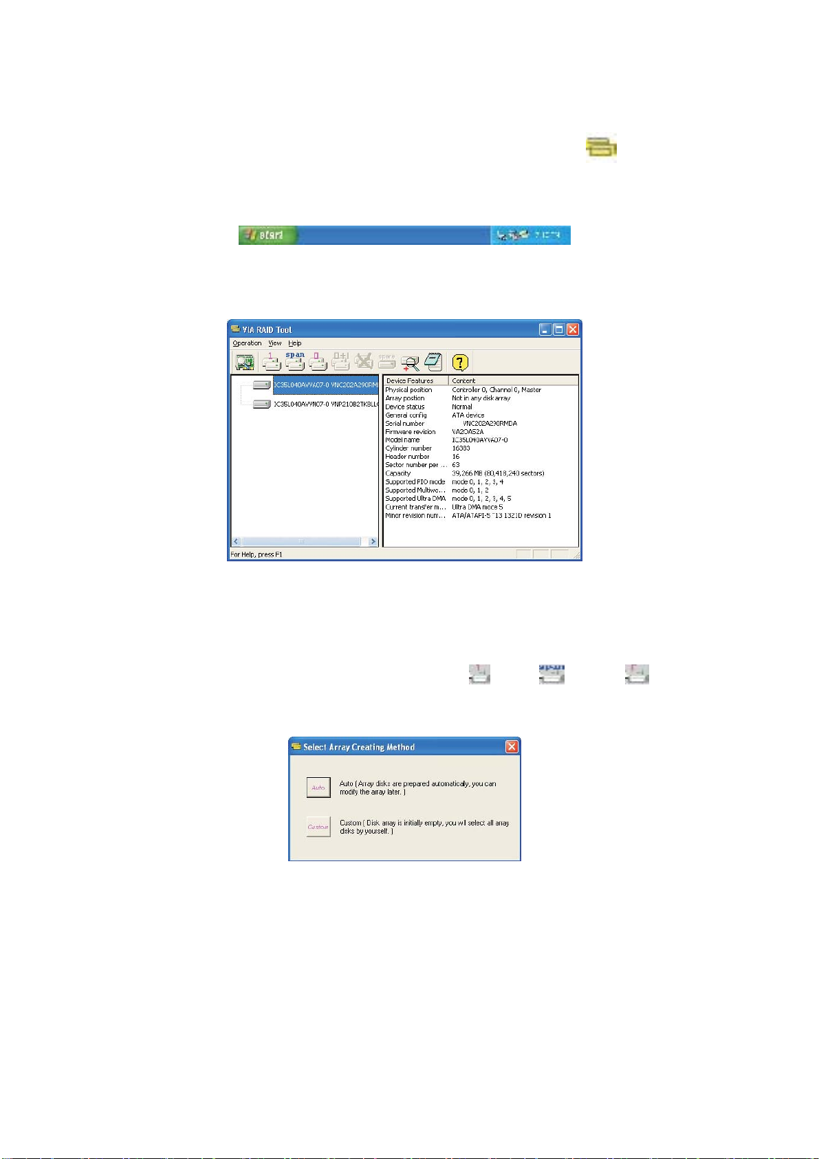
After GUI software is installed, it will automatically start every time when your Windows OS is started. An icon
tray of the tool bar to indicate that GUI software is currently running.
Just double click on the small icon to call out the main interface of the software.
will appear in the system
2.2.1 Create Disk Array
1. You may click on one of the three buttons to create different types of disk array– RAID 1, Span, and RAID 0. Then a
“Select Array Creating Method” will be prompted.
Auto:
The software will configure the available hard disk drives to be a disk array. User can modify the hard disk drives later. It is strongly recommended
to use this method.
Custom:
Disk array is arranged by user.
9
Page 10

2. Click “Auto” button. The “Creating Array” window will pop up. If you select “Custom”, the “Available Disks” window will list the available disk
drives for array-creating. Select a disk drive and click right arrow button to add the specific disk drive to array. After adding a disk drive, user
can also remove the selected disk drive from array. Click the disk drive in “Array Disks” windows, then click left arrow button to remove the
selected disk drive.
Press “Create” button to create or “Cancel” button to cancel it.
After you pressed the “Create” button, a warning message will pop up. Click “Yes” to finish the creation of disk array, or “No” to cancel.
3. A message box will pop up to prompt user that the disk array has been created successfully and ask user whether to restart the computer.
Click “Yes” to restart the computer or click “No” to skip restarting. New disk array setting will take effect only after restarting.
Create RAID 1
You can reserve the data on the source drive after clicking “Create” button when you create a RAID 1 array.
10
Page 11

There is a limitation if user wants to keep the data on the source drive the capacity of the mirror drive must be greater or equal to the source drive,
otherwise the RAID 1 can’t be created.
If user wants to keep data in the source drive, RAID tool will ask user to synchronize the mirror drive after the system’s rebooting.
Create JBOD
The data in the first disk drive of JBOD array can be reserved when a JBOD array is created.
The data on the first disk drive will be reserved and the other disk drives in JBOD will be expanded behind the first disk drive and become free
space.
2.2.2 Delete Disk Array
1. Select the disk array that you want to delete from the left window. Click “Remove Array” button , then a warning message will pop up.
2. Click “Yes” to delete the specific disk array or click “No” to cancel.
11
Page 12

3. A message box will pop up to prompt user that the disk array has been deleted successfully and ask user whether to restart the computer.
Click “Yes” to restart the computer or click “No” to skip the restarting. New setting will take effect only after restarting.
Warning:
Deleting a disk array will destroy all the data on the disk array except RAID 1. When a RAID is deleted, the data on these two hard disk drives will be
reserved.
2.2.3. Check All Disks
You can check if all the disk drives work normally by clicking button. After you complete the checking, a dialog window will pop up to show each
disk’s current status as following picture.
Your hard disk drive must be compatible with ATA/ATAPI-5 specifications and support SMART commands; otherwise the checking will fail.
2.2.4 Verify Mirror Disk
Data on the mirror disk must be the same as its corresponding source disk to provide fault tolerance for RAID 1.
1. Select a RAID 1. Right-click the selected RAID, and then a shortcut menu will appear. Click “Verify Mirror” to verify whether the source and
the mirror disks are identical.
12
Page 13

2. After executing “verify mirror” command, a dialog will show the verifying process. You can pause or cancel this process at any time. The
process may take a long time if the capacity of RAID is large.
3. When the mirror disk is not identical with the corresponding source disk, the mirror disk will be marked with a “need-sync” icon:
“need-sync” mirror disk should be synchronized as soon as possible.
. A
2.2.5 Synchronize Mirror Disk
For RAID 1, it must be synchronized when data on the mirror disk is not identical with its corresponding source disk. Sometimes the data on the
mirror disk may be newer than the source disk. For example, the source disk is absent and the mirror disk runs in the tolerance mode. So the
exact meaning of “Synchronize Mirror” is to keep the data on a pair of the source and the mirror disks identical. RAID software always marks
the mirror disk with a “need-sync” icon
1. Select RAID 1. Right-click the selected RAID, then a shortcut menu will appear. Click “Synchronize Mirror” to synchronize the source and the
mirror disks.
even though the mirror disk may have the correct data.
13
Page 14

2. When synchronization starts, a dialog will show the process. You can pause or cancel this process at any time.
3. A message will pop up when synchronization is finished.
2.2.6 Disk Error Detection
RAID will pop up an error message when the failure or absence of a disk drive is detected.
2.2.7 Duplicate Critical RAID 1 Array
14
Page 15

If, during the system-booting, the software detects the inconsistence between the source and the mirror disks of RAID 1, the disk array will be
marked as critical status, and the software will automatically prompt user to duplicate the RAID 1 to make the mirror disk consist with the
corresponding source disk again.
You may click “Yes” to synchronize now or click “No” to synchronize later.
When the synchronization starts, a dialog will show the process. You can pause or cancel this process at any time. If you cancel the
synchronization process, the RAID is on “need-sync” condition. You should synchronize again to guarantee the data are identical between the
source and the mirror disk drives. A message will pop up when synchronization is finished.
2.2.8 Rebuild Broken RAID 1 array
If, during the system-booting, the failure or absence of any member disk of RAID is detected, the array will be marked as broken status. If broken
RAID 1 array is detected by the RAID software, it will indicate a serial steps to repair this problem.
1. A dialog box will pop up to indicate the RAID is broken. Click Yes.
2. Then another dialog box will pop up. If the source or the mirror disk drive is unplugged only, click “Cancel” to stop rebuilding step. Shut down
the system. Plug the absent disk drive, and then reboot the system. If the original disk drive is broken-down, you may plug a new disk drive
15
Page 16

then reboot the system. Click “Next” to the next step.
3. Select a disk drive from “Available Disks” and click
button to replace the broken-down one, and then click “Next”.
4. A warning message will pop up. If you want to rebuild the RAID by using the disk drive that you selected in the previous step, click “Next”.
Warning: The data on the selected disk drive will be lost.
16
Page 17

5. Reboot the system.
6. This RAID is marked as a critical RAID. The RAID software will do the “Duplicating Critical RAID 1” process.
3. JMicron RAID Installation Guide
If you insert two HDDs to JMicron SATAII connectors and plan to configure RAID functions, please refer to JMicron RAID installation guide part,
including JMicron BIOS RAID installation guide and JMicron Windows RAID installation guide.
3.1 JMicron BIOS RAID Installation Guide
You are allowed to configure RAID functions under BIOS environment.
3.1.1 BIOS Configuration Utility
3.1.1.1 Enter BIOS Configuration Utility
17
Page 18

After the system powers on, the following information will appear on the screen. Press ‘Ctrl-J’ key to enter BIOS configuration utility.
The main interface of BIOS configuration utility is as below:
3.1.1.2 Create RAID Disk Drive
Entering “Create RAID Disk Drive” item, you can see the below window. Before you create RAID, you need to select RAID mode, as you want.
18
Page 19

When you push “Create RAID Disk Drive” item to enter RAID selection menu, you can use <↑> <↓> to select RAID mode.
There are three RAID modes that are RAID 0, RAID 1, and JBOD.
19
Page 20

Then you can select HDDs to create RAID. Entering “Select Disk Drives” item, use <Space> to choose the HDDs you want to select.
After selecting HDD to create RAID. You can choose Block Size from 4K to 128K Bytes in RAID Mode.
20
Page 21

After finishing all selections, press <Enter> to confirm RAID construction. The Dialog Box will show up “Create RAID on the select
HDD (Y/N)?” If you enter <Y> key, RAID will be created. If you enter <N> key, RAID setting will be ignored and RAID is not created.
All original data in HDD List of RAID will be damaged after you enter <Y> key to create RAID.
3.1.1.3 Delete RAID Disk Drive
If you want to delete existed RAID, you can select “Delete RAID Disk Drive” item. Use <Space> key to select the RAID you want to
delete. After selection, push <Del> key to confirm your deletion of RAID.
3.1.1.4 Revert HDDs to non-RAID
When you connect your HDD in PC system, there might be a Broken RAID HDD that is member of another RAID originally. Facing this kind of
21
Page 22

condition, JMB36X RAID BIOS provides you to convert Broken RAID HDD into non-RAID mode. Once you decide to do it, original data in Broken
RAID HDD will be damaged. When new RAID is created through JMB36X, Broken RAID HDD is forbidden to select to avoid to damaging your
system. This function is used for deleting RAID structure of single RAID HDD.
3.1.1.5 Solve Mirror Conflict
When your mirror raid drive has lost each other, the Option ROM gives users an method to solve this problem. You can choose one of the
members of Mirror drive as source disk. And then try to rebuild the Mirror drive according to the content of chosen one.
3.1.1.6 Rebuild Mirror Drive
This option will help you to rebuild Mirror drive. The bottom of the window will show the achieved percentage of scheduled progress.
22
Page 23

3.2 JMicron Windows RAID Installation Guide
JMRaidTool application is an utility to set up the RAID configuration of JMB36X. There are two kinds of information displayed in the main utility
window: the information of all hard disks and the disk array.
3.2.1 Creating RAID
JMRaidTool supports the creation of RAID 0 (Stripe), 1 (Mirror), and JBOD. When the raid array is created, the data in the disks will be erased
meanwhile. The disks of the raid array need to be initialized and partitioned before using it.
Left-click the “Create RAID” button. And press<Next>.
Key-in the name of the raid array.
23
Page 24

Select the RAID type.
Select the block size.
24
Page 25

Select hard disks and then press “Next” button.
Press the “Finish” button to create a new raid array. Then the information of the created raid array will be displayed in the window.
3.2.2 Creating RAID from Existing Disk
JMRaidTool supports the RAID creation from the existing disk. The data of the existing source disk will be kept and will not be erased when the
new disk array is created. The existing source disk should be a non-RAID disk.
Left-click the “Create RAID from Existing Disk” button. Then follow the instruction shown on the windows. The procedures are similar to the steps
of creating RAID.
25
Page 26

3.2.3 Deleting RAID
This options provides a popup menu for users to delete the existing disk arrays.
Right-click the name of the disk array that you want to delete and then a popup menu will appear. Users could select “Remove Raid” item to
remove the selected disk array.
3.2.4 Rebuilding RAID
RAID 1 can be rebuilt while RAID 0, JBOD cannot be rebuilt. While one disk member of RAID 1 is broken or is unplugged, there is an exclamation
mark on the RAID. Users could use a new and robust disk to rebuild the RAID.
26
Page 27

Right-click the name of the raid array you want to rebuild and then a popup menu will appear. Users could select the “Rebuild Raid” menu item to
rebuild RAID.
3.2.5 Auto-Resynching RAID
While one disk member of RAID 1 is unplugged, JMRaidTool application will auto-resynchronize the raid when the disk is plugged again.
27
 Loading...