

VIA IB781 motherboard

IB781
VIA CLE266 Full Size CPU Card
USER’S MANUAL
Version 1.0B

ii IB781 User’s Manual
Acknowledgments
Award is a registered trademark of Award Software International,
Inc.
PS/2 is a trademark of International Business Machines
Corporation.
Microsoft Windows is a registered trademark of Microsoft
Corporation.
Winbond is a registered trademark of Winbond Electronics
Corporation.
All other product names or trademarks are properties of their
respective owners.

IB781 User’s Manual iii
Table of Contents
Introduction....................................................... 1
Product Description.......................................................... 1
Specifications................................................................... 2
Board Dimensions............................................................ 3
Installations....................................................... 5
Installing the Memory (DDR DIMM)............................... 6
Setting the Jumpers .......................................................... 7
Connectors on IB781...................................................... 11
BIOS Setup...................................................... 23
Drivers Installation...................................... 45
Appendix........................................................... 51
A. I/O Port Address Map................................................ 51
B. Interrupt Request Lines (IRQ).................................... 52
C. Watchdog Timer Configuration.................................. 53

iv IB781 User’s Manual
This page is intentionally left blank.

INTRODUCTION
IB781 User’s Manual 1
Introduction
Product Description
IB781 is a high-performance flexible embedded board based on the VIA
CLE 266 chipset. The chipset is based on an innovative and scaleable
architecture with proven reliability. It is a two-chip set consisting of the
VT8623 North Bridge Controller and VT8235 South Bridge Controller.
IB781 supports the Socket 370 processors with speeds of up to 1.4GHz
and with front side bus of up to 133MHz. Two 184-pin DDR DIMM
sockets support can accommodate a total memory size of 2GB.
Combining a fully integrated video processing feature set, Integrated
UniChrome™ 2D/3D graphics engine and ultra efficient VIA DDR
memory controller, the VIA Unichrome™ CLE266 Chipset is designed
to enable high quality digital video streaming and DVD playback in a
new generation of small form factor PCs and IA devices. Shared
memory capacity is up to 64MB.
One 10/100Mbps Ethernet onboard is supported by the Realtek 8100C
single chip Ethernet controller or it can replaced with an optional
RTL8110s-32 Gigabit LAN.
With dimensions of 338mm x 122mm, IB781 has other features such as
Watchdog timer, DiskOnChip socket, four USB 1.1/2.0 ports.

INTRODUCTION
2 IB781 User’s Manual
Specifications
Form Factor PICMG (Full Size CPU Card)
CPU Type Socket 370 (Intel PIII / Celeron)
CPU Voltage 1.1V~1.85V
System Speed 533MHz~1.4GHz
CPU External
Clock
66/100/133Mhz
Green /APM APM1.2
CPU Socket Socket 370
Chipset North Bridge: 548 pin VT8623 (2D/3D)(CLE266)
South Bridge: 487 pin VT8235 CD
BIOS Award BIOS, 2Mbit support ACPI function
Cache CPU integrated
Memory
two 184-pin DDR DIMM socket supports ,
Supports DDR200/266 DDR DIMM Max.2GB
VGA VT8623 Integrated AGP 4X, 2D 128 Bit 3D 128
Bit VGA controller, Analog
MPEG-2
Hardware
Slice Layer, IDCT & Motion Compensation
LCD interface Support 24-bit TTL LCD, 18BIT LVDS
LAN RTL 8100C(L)(10/100) or RTL8110s-32
(10/100/1000) Single
Chip Ethernet Controller.
Sound VT8235 Built Sound controller + AC97 Codec
ALC655 (Line-out, Line-in, Mic)
LPC I/O Winbond 83697HF: Parallel x1, COM1, COM2,
FDC 2.88MB (3 Mode Support), Hardware
monitor (3 thermal inputs, 8 voltage monitor
inputs, VID0-4, 1 chassis open detection, 3 Fan
Header)
PCI TO ISA
Bridge
ITE IT8888
ISA High Drive Yes
Disk On Chip Yes
UART/16550A COM1: RS232
COM2: RS232/422/485
RTC/CMOS VT8235 built-in
Battery Lithium battery
Keyboard/Mouse VT8235 built-in
IDE VT8235 built-in, IDE1, 2 (Ultra DMA
33/66/100/133)
USB Supports 1.1/2.0 USB 4 ports
Watchdog Timer 256 levels
INTRODUCTION
IB781 User’s Manual 3
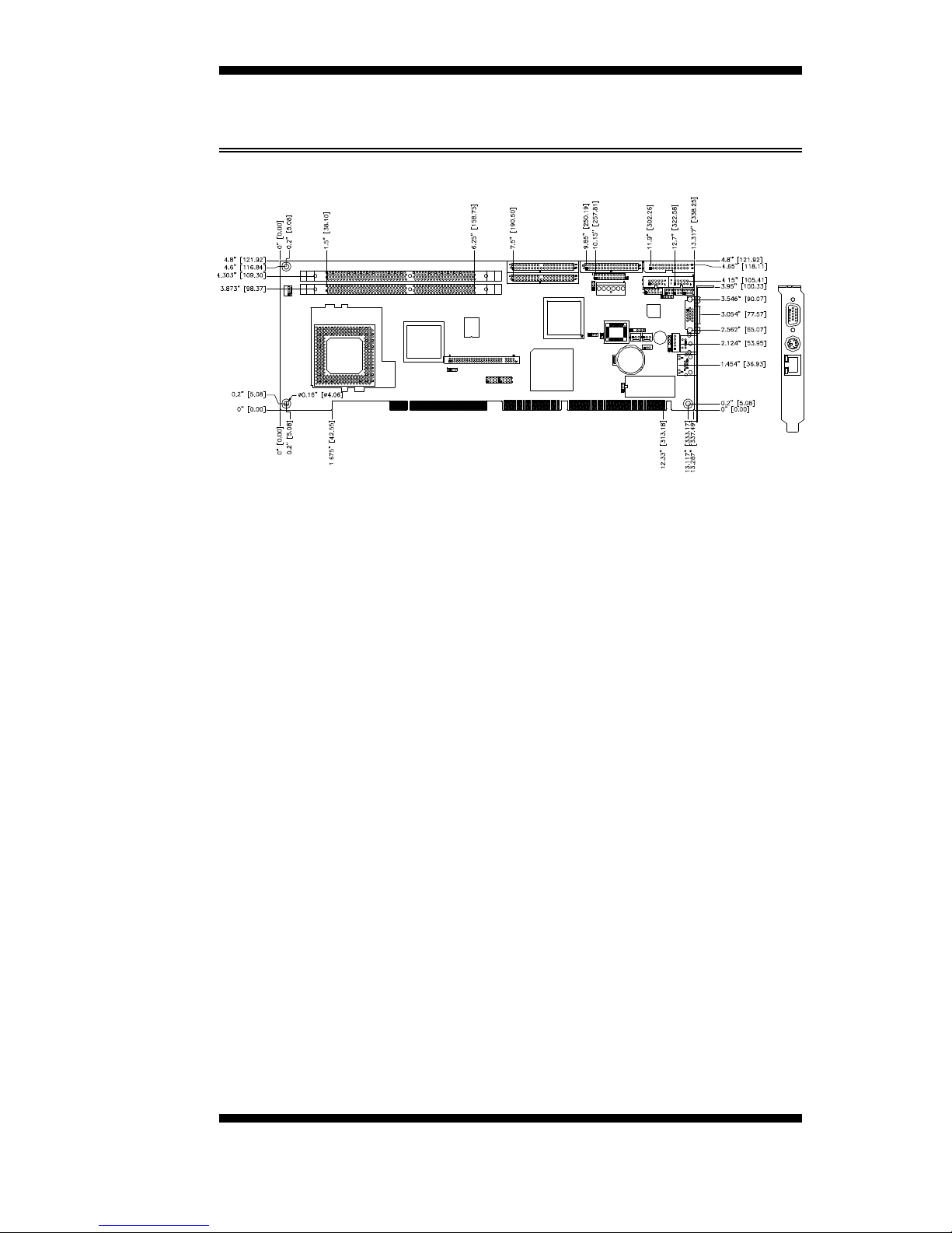
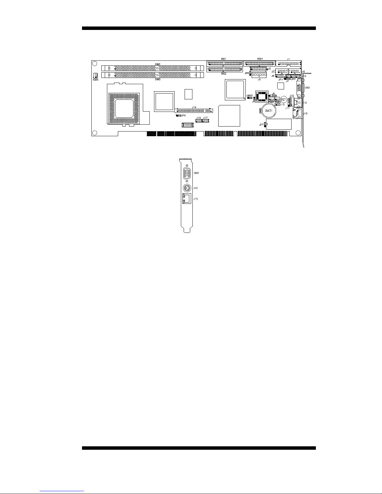
Board Dimensions

INTRODUCTION
4 IB781 User’s Manual
This page is intentionally left blank.

INSTALLA
TIONS
IB781 User’s Manual 5
Installations
This section provides information on how to use the jumpers and
connectors on the IB781 in order to set up a workable system. The topics
covered are:
Installing the Memory (DDR DIMM)............................... 6
Setting the Jumpers..........................................................7
Connectors on IB781...................................................... 11
INSTALLATIONS
6 IB781 User’s Manual
Installing the Memory (DDR DIMM)
The IB781 board supports one 184-pin DDR DIMM socket for a
maximum total memory of 1GB in DDR DRAM type. The memory
module capacities supported are 64MB, 128MB, 256MB, 512MB and
1GB.
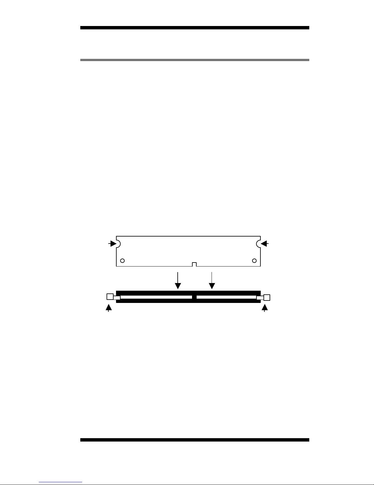
Installing and Removing DIMMs
To install the DDR DIMM, locate the memory slot on the board and
perform the following steps:
1. Hold the DIMM so that the two keys of the DIMM align with those on
the memory slot.
2. Gently push the DIMM in an upright position until the clips of the slot
close to hold the DIMM in place when the DIMM touches the bottom
of the slot.
3. To remove the DDR module, press the clips with both hands.
Top View of DIMM Socket
DDR Module
Lock
Lock
Lock
Lock

INSTALLA
TIONS
IB781 User’s Manual 7
Setting the Jumpers
Jumpers are used on IB781 to select various settings and features
according to your needs and applications. Contact your supplier if you
have doubts about the best configuration for your needs. The following
lists the connectors on IB781 and their respective functions.
Jumper Locations on IB781.......................................................... 8
JP8: AT / ATX Power Select ........................................................9
JBAT1: Clear CMOS Content.......................................................9
JP1, JP2, JP3: RS232/RS422/RS485 (COM2) Selection................ 9
JP6: LCD Panel Power Selection ................................................ 10
JP7: DiskOnChip 2000 Address.................................................. 10
INSTALLATIONS
8 IB781 User’s Manual
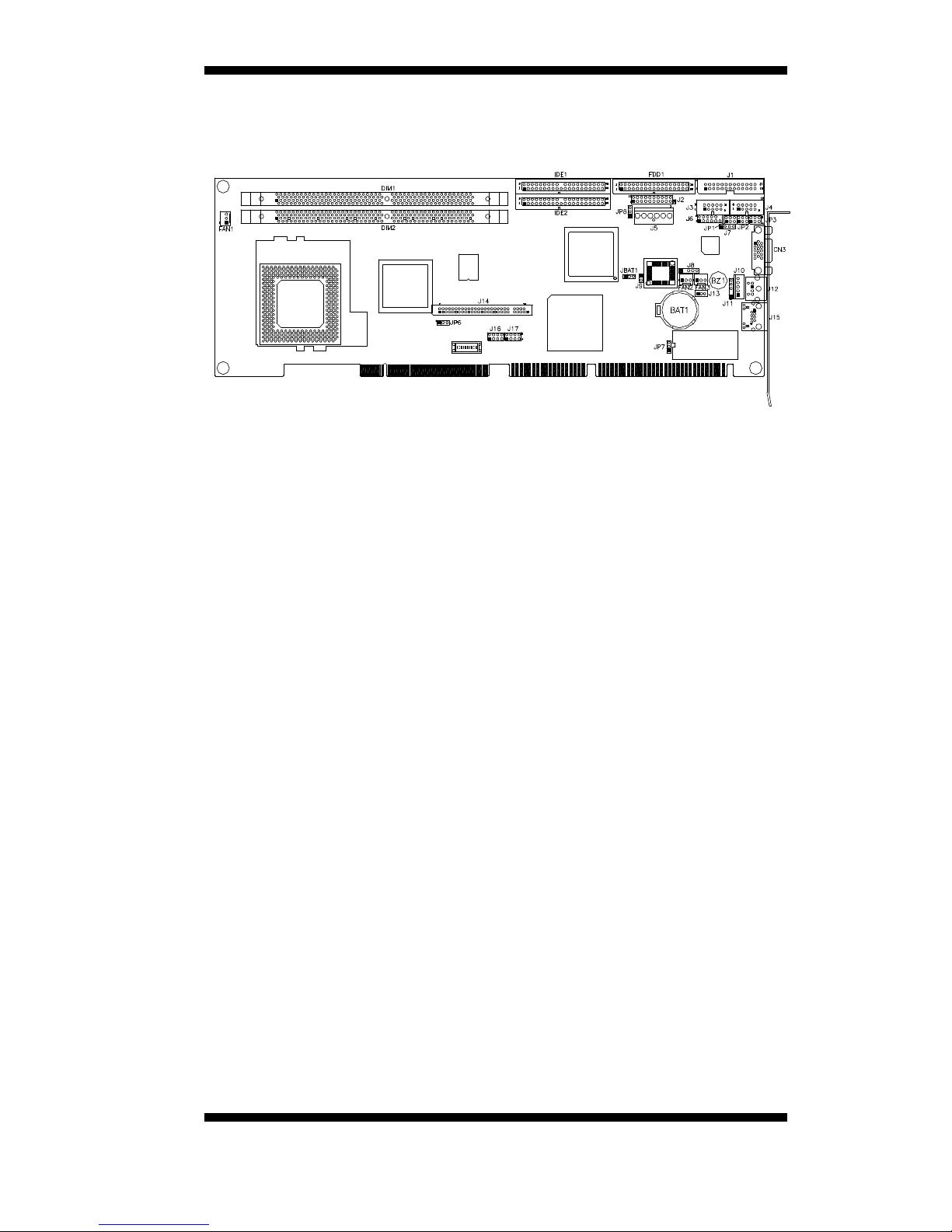
Jumper Locations on IB781
Jumpers on IB781...................................................................Page
JP8: AT / ATX Power Select........................................................ 9
JBAT1: Clear CMOS Content...................................................... 9
JP1, JP2, JP3: RS232/RS422/RS485 (COM2) Selection................ 9
JP6: LCD Panel Power Selection.................................................10
JP7: DiskOnChip 2000 Address...................................................10
INSTALLA
TIONS
IB781 User’s Manual 9
JP8: AT / ATX Power Select
JP8 Setting Power Supply
Pin 1-2
Short/Closed
AT
Pin 2-3
Short/Closed
ATX
JBAT1: Clear CMOS Content
JBAT1 Setting Function
Pin 1-2
Short/Closed
Normal Operation
Pin 2-3
Short/Closed
Clear CMOS Content
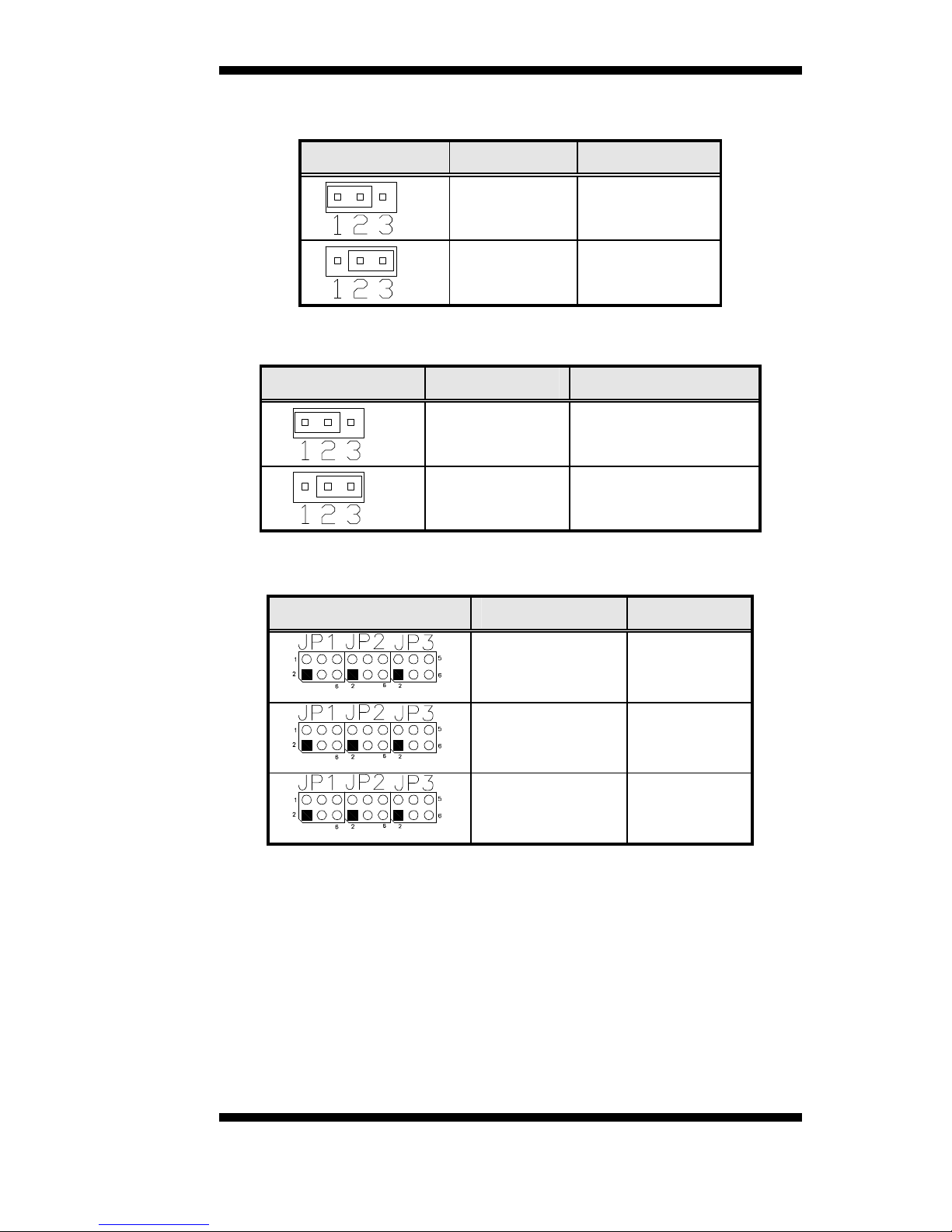
JP1, JP2, JP3: RS232/RS422/RS485 (COM2) Selection
JP1, JP2, JP3 Pin Short Function
JP1: 1-2
JP2: 3-5, 4-6
JP3: 3-5, 4-6
RS232
JP1: 3-4
JP2: 1-3, 2-4
JP3: 1-3, 2-4
RS422
JP1: 5-6
JP2: 1-3, 2-4
JP3: 1-3, 2-4
RS485

INSTALLATIONS
10 IB781 User’s Manual
JP6: LCD Panel Power Selection
JP6 Setting Voltage
Pin 1-2
Short/Closed
3.3V
Pin 2-3
Short/Closed
5V
JP7: DiskOnChip 2000 Address
JP7 Setting Address
Pin 1-2
Short/Closed
OD000H-OD1FFH
Pin 2-3
Short/Closed
OD800H-OD9FFH

INSTALLA
TIONS
IB781 User’s Manual 11
Connectors on IB781
The connectors on IB781 allows you to connect external devices such as
keyboard, floppy disk drives, hard disk drives, printers, etc. The
following table lists the connectors on IB781 and their respective
functions.
Connector Locations on IB781 ................................................... 12
FAN1, FAN2: CPU and System Fan Power Connectors.............. 13
FAN3: ATX Power Connector.................................................... 13
IDE1, IDE2: EIDE Connectors................................................... 13
FDD1: Floppy Drive Connector.................................................. 14
J1: Parallel Port Connector ......................................................... 15
J2: System Function Connector................................................... 15
J3, J4: COM1 and COM2 Serial Ports Connector........................ 17
J5: AT P8 Power Supply Connector............................................ 17
CN3: VGA CRT Connector........................................................ 18
J6: External Audio Connector..................................................... 18
J7: CD-In Audio Connector........................................................18
J8: IrDA Connector ....................................................................18
J10: External PS/2 Keyboard Connector ..................................... 19
J11: External PS/2 Mouse Connector.......................................... 19
J12: PS/2 Keyboard and Mouse Connector.................................. 19
J13: Wake On LAN Connector ...................................................19
J14: LVDS Connector (18-bit).................................................... 20
J15: Gigabit LAN RJ45 Connector ............................................. 20
J16, J17: USB Connectors..........................................................20
J18: TTL Connector ................................................................... 21
FPD RGB Mapping Table ..........................................................22
INSTALLATIONS
12 IB781 User’s Manual
Connector Locations on IB781
Connectors on IB781..................................................................................................Page
FAN1, FAN2: CPU and System Fan Power Connectors......................... 13
FAN3: ATX Power Connector............................................................... 13
IDE1, IDE2: EIDE Connectors.............................................................. 13
FDD1: Floppy Drive Connector............................................................. 14
J1: Parallel Port Connector.................................................................... 15
J2: System Function Connector ............................................................. 15
J3, J4: COM1 and COM2 Serial Ports Connector................................... 17
J5: AT P8 Power Supply Connector....................................................... 17
CN3: VGA CRT Connector................................................................... 18
J6: External Audio Connector................................................................ 18
J7: CD-In Audio Connector................................................................... 18
J8: IrDA Connector............................................................................... 18
J10: External PS/2 Keyboard Connector ................................................ 19
J11: External PS/2 Mouse Connector..................................................... 19
J12: PS/2 Keyboard and Mouse Connector............................................. 19
J13: Wake On LAN Connector.............................................................. 19
J14: LVDS Connector (18-bit)............................................................... 20
J15: Gigabit LAN RJ45 Connector ........................................................20
J16, J17: USB Connectors..................................................................... 20
J18: TTL Connector.............................................................................. 21
INSTALLA
TIONS
IB781 User’s Manual 13
FAN1, FAN2: CPU and System Fan Power Connectors
Pin #
Signal Name
1 Ground
2 +12V
3 Rotation detection
FAN3: ATX Power Connector
Pin #
Signal Name
1 Ground
2 PS_On
3 5VSB
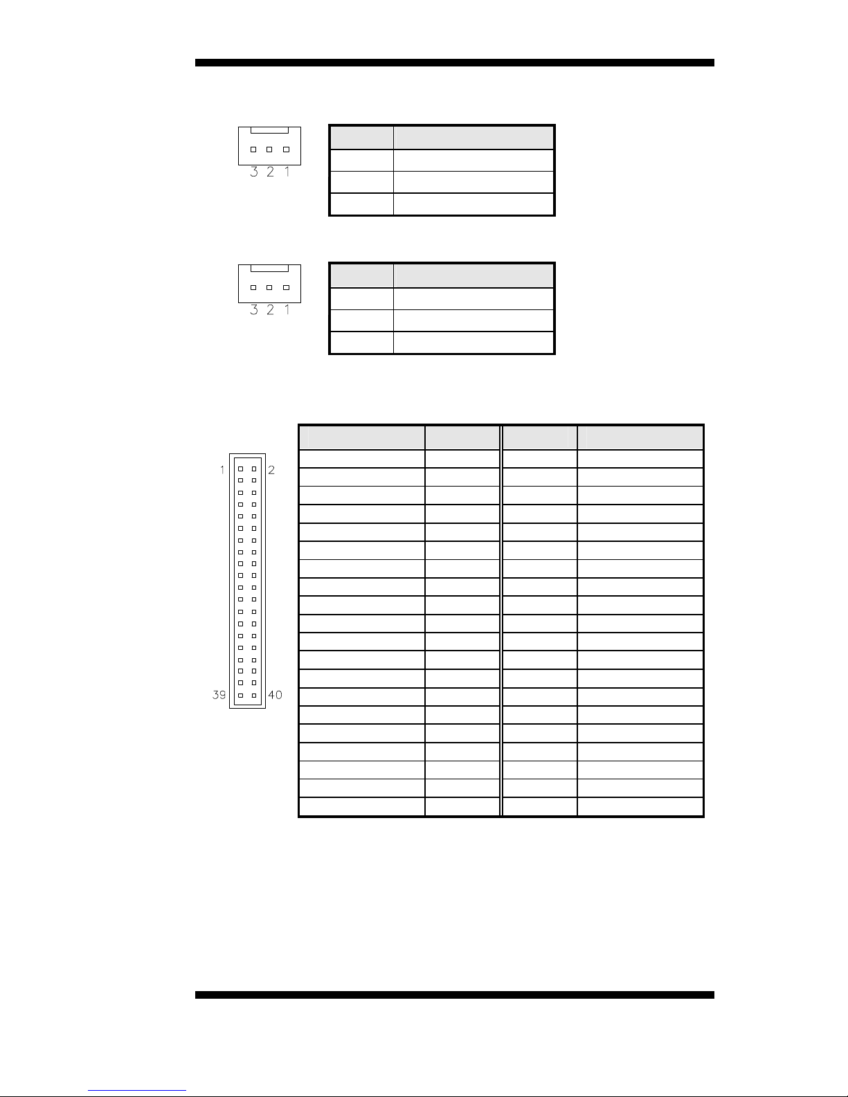
IDE1, IDE2: EIDE Connectors
IDE1: Primary IDE Connector
Signal Name Pin # Pin #
Signal Name
Reset IDE 1 2 Ground
Host data 7 3 4 Host data 8
Host data 6 5 6 Host data 9
Host data 5 7 8 Host data 10
Host data 4 9 10 Host data 11
Host data 3 11 12 Host data 12
Host data 2 13 14 Host data 13
Host data 1 15 16 Host data 14
Host data 0 17 18 Host data 15
Ground 19 20 Protect pin
DRQ0 21 22 Ground
Host IOW 23 24 Ground
Host IOR 25 26 Ground
IOCHRDY 27 28 Host ALE
DACK0 29 30 Ground
IRQ14 31 32 No connect
Address 1 33 34 No connect
Address 0 35 36 Address 2
Chip select 0 37 38 Chip select 1
Activity 39 40 Ground
INSTALLATIONS
14 IB781 User’s Manual
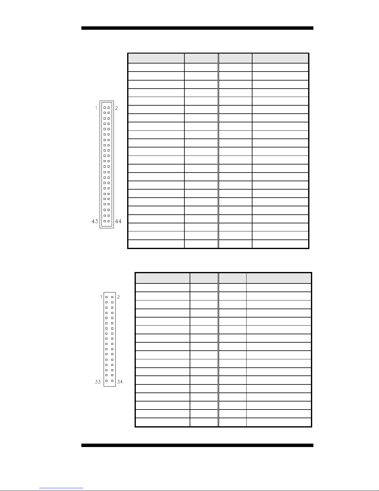
IDE2: Secondary IDE Connector
Signal Name Pin # Pin # Signal Name
Reset IDE 1 2 Ground
Host data 7 3 4 Host data 8
Host data 6 5 6 Host data 9
Host data 5 7 8 Host data 10
Host data 4 9 10 Host data 11
Host data 3 11 12 Host data 12
Host data 2 13 14 Host data 13
Host data 1 15 16 Host data 14
Host data 0 17 18 Host data 15
Ground 19 20 Key
DRQ0 21 22 Ground
Host IOW 23 24 Ground
Host IOR 25 26 Ground
IOCHRDY 27 28 Host ALE
DACK0 29 30 Ground
IRQ14 31 32 No connect
Address 1 33 34 No connect
Address 0 35 36 Address 2
Chip select 0 37 38 Chip select 1
Activity 39 40 Ground
Vcc 41 42 Vcc
Ground 43 44 N.C.
FDD1: Floppy Drive Connector
Signal Name Pin # Pin #
Signal Name
5V/Ground 1 2 RM/LC
5V/Ground 3 4 No connect
5V/Ground 5 6 No connect
Ground 7 8 Index
Ground 9 10 Motor enable 0
Ground 11 12 Drive select 1
Ground 13 14 Drive select 0
Ground 15 16 Motor enable 1
Ground 17 18 Direction
Ground 19 20 Step
Ground 21 22 Write data
Ground 23 24 Write gate
Ground 25 26 Track 00
Ground 27 28 Write protect
Ground 29 30 Read data
Ground 31 32 Side 1 select
Ground 33 34 Diskette change
 Loading...