

Page 1
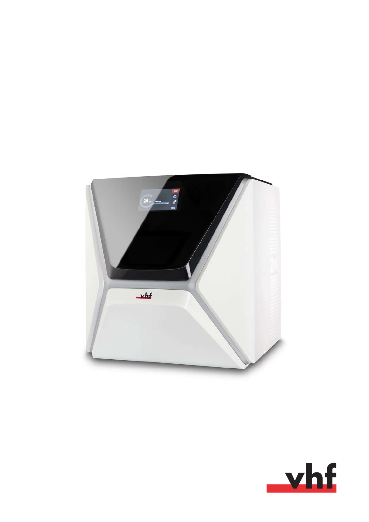
Original Operating
Instructions
Z4
Originalbetriebsanleitung
Instrucciones de uso originales
Mode d’emploi d’origine
Istruzioni d’uso originali
dentalportal.info
Page 2

Page 3

Contents
EN 3
1 Welcome 5
About this document 5
Used symbols 5
Structure of safety notes 5
2 General safety instructions 6
3 Operating regulations 8
Intended use 8
Controlling the mac hine through software 8
Maintenance and cleaning 8
Spindle 8
Unattended operation 8
Transportation and storage 9
4 Machine overview 10
Front side of the machine 10
Rear side of the machine 10
Touchscreen 11
Working chamber door 11
Working chamber 11
Multi-purpose drawer 12
Required computer hardware software 12
Sound emission 12
Location of the identification plate serial number 13
Technical data 14
5 Installing the machine 15
Checking the scope of delivery 15
Choosing the installation site 16
Establishing the electric connection 18
Removing the transport lock 18
Checking the tool magazines in the drawer 18
CAD computer network integration 19
Internal CAM computer 19
Preparing the machine and CADcomputer 19
Accessing the CAM computer 20
Integrating the CAD with the CAM/ CNC software 24
6 Operation: Preparing jobs 31
Starting the machine 31
Starting the machine with a tool in the collet chuck 32
Shutting down the machine 33
If there is no connection to the CAM computer 33
Opening closing the working chamber door 34
Opening closing the multi-purpose drawer 35
The user interface on the touchscreen 36
The Home section of the touchscreen 36
The Jobs section of the touc hscreen 37
The Toolssection of the user interface 38
Exchanging the cooling liquid and cleaning the tank 38
Emptying the strainer basket 38
Exchanging or filling in the cooling liquid 39
Managing tools 41
Color codes of the tool magazines 41
Inserting and exchanging tools 41
Mounting exchanging tool magazines 43
Mounting removing blanks 46
7 Operation: Executing jobs 47
Overview 47
Starting jobs via the touchscreen 47
Aborting machining 49
Job interruptions and job abortions 49
How to proceed in case of a job interruption 50
How to proceed in case of a machine malfunction 50
How to proceed in case of a tool breakage 50
How to proceed in case of a power failure 50
Emergency opening of the working chamber door 51
Removing the back panel cover 52
Emergency opening of the multi-purpose drawer 52
8 Maintenance and do-it-yourself 53
Basic maintenance 53
Maintenance section 53
Preventive maintenance 53
Where to get service? 53
Definition of wear parts 53
Using the maintenance section 54
List of all maintenance tasks 55
Performing maintenance tasks 55
Leaving the Maintenance section 56
Cleaning the working chamber 57
Cleaning the collet chuck 58
Cleaning the nozzle plate 60
Cleaning the collet chuck of the blank holder 60
Rinsing the cooling liquid circuit 62
Exchanging the carbon filter 63
Cleaning the housing 64
Exchanging the main fuse 64
Calibrating the axes 65
Replacing the tool magazine inserts 65
Exchanging the coupling of the cooling liquid tank 66
Exchanging the view window wiper 67
Updating the software and firmware 68
Original Operating Instructions:Z4
Version: 12/5/2018
Page 4

EN 4
Updating the firmware of the machine 68
Updating DentalCAM DentalCNC 68
Maintenance table 69
9 Disposal 71
Disposing of the cooling liquid 71
Disposing of the machine 71
10 Troubleshooting 72
Index 75
Contents
Original Operating Instructions:Z4
Version: 12/5/2018
Page 5
Welcome
EN 5
1 Welcome
Thank you for your purchase of this Z4 dental
machine. The machine is delivered to you with pride
and confidence. It was produced using the latest techniques and strict quality control.
These operating instructions were prepared to help
you understand all functions of your new dental
machine. It should also help you keep the machine in
good conditions so that you may enjoy many hours of
productive work.
You may find updates to this document at:
dentalportal.info – search for
About this document
This document is designed and released for the
following groups/ individuals:
Authorized resellers
n
Authorized service technicians
n
Used symbols
Instructions
Single or general instruction
1.
Numbered action step
Result
Z4
Information to make work more efficient
Important information without any danger for
people or objects
Additional information
Structure of safety notes
SIGNAL WORD
Type and source of hazards
Further explanations and consequences when
ignoring the hazard.
Instructions to avoid the hazard.
The following signal words may be used:
DANGER
DANGER indicates a hazardous situation which will
result in death or serious injury.
WARNING
WARNING indicates a hazardous situation which can
result in death or serious injury.
Additional symbols
Cross reference
List (first level)
n
List (second level)
1.
Numbered image labels
CorrectorDo this
IncorrectorDo not let this happenorDont
do this
CAUTION
CAUTION indicates a hazardous situation which can
result in minor or moderate injury.
NOTICE
NOTICE indicates a situation which can lead to physical damage of the product or in the surrounding
areas.
Original Operating Instructions:Z4
Version: 12/5/2018
Page 6
EN 6
Z4 – General safety instructions
2 General safety
instructions
DANGER
Incorrect operation of the machine
Before
machine, read
machine.
If it is unclear how to operate the machine in any
way, do not use the machine and contact customer service.
Ensure that every user has access to the operating
instructions.
Instruct every user on safe and proper machine
handling.
Danger to life due to an electric shock
ficantly.
Do not remove the housing of the machine.
Only have qualified electricians work on any electric equipment.
Ensure that an operational Residual Current
Device/ Ground Fault Circuit Interrupter is
installed on the electric circuit of the machine.
Run power cables so that they cannot be damaged by sharp edges.
Before
cables for damage.
Before
the machine at the main power switch.
diately and prevent it from being restarted:
n
n
n
Replace damaged cables with original manufacturers spare parts.
Never perform any troubleshooting while the
machine is operating.
Only have authorized service technicians repair
the machine.
installing, maintaining and operating the
documents provided with the
all
If you come into contact with electrically
charged parts, you can suffer from an electrical shock. Water increases the risk signi-
switching on the machine, check power
unplugging the power cable, switch off
In the following cases, disconnect the
machine from the electrical source imme-
When machine connections or electric cables are
damaged
When water is leaking
Before
you check or run electric cables
Do not touch the machine and especially the
cables with wet or damp hands.
Check the environment of the machine and all
accessible internal areas daily for leaked liquid and
remove any liquids near or in the machine immediately.
Never put any machines or devices which are
powered by electricity under the machine.
Do not put any objects onto the machine.
WARNING
Respiratory diseases when processing
harmful materials
If you inhale harmful materials during their processing,
your respiratory tracts may be damaged.
Avoid materials which damage your health.
Crushing hazard and risk of cutting injuries
through moving machine parts
Through the moving axes and the rotating spindle you
can suffer bruises and cuts.
Only use the machine when the working chamber
door is completely closed and undamaged during
machining.
Do not circumvent or deactivate safety devices of
the machine.
Check the machine regularly for damage, especially the safety devices.
Have damaged safety devices repaired by customer service only.
Use only original manufacturer’s equipment and
original spare parts in the machine.
Keep children and animals away from the
machine.
Do not remove the housing of the machine.
Service Mode: Risk of cutting injuries and
bruises as well as hazards through ejected
debris
If you operate the machine in any “Service Mode”
with the working chamber door open, the risk of
injury is increased significantly.
Operate the machine in “User“mode only unless
you have been authorized by the machines manufacturer to use other modes.
Even if you are an authorized user, use the “Service Modes” only when necessary.
While in any “Service Mode”: Do not reach
into the working chamber while the axes are
Original Operating Instructions:Z4
Version: 12/5/2018
Page 7
Z4 – General safety instructions
EN 7
moving or during machining.
While in any “Service Mode”: Everyone
within reach of the machine must wear pro-
tective eye wear.
Hearing damage due to loud noise
If you are regularly exposed to loud machining noise,
you may suffer from hearing loss and tinnitus.
If loud noise cannot be avoided, wear ear
protection during machining.
CAUTION
Risk of injuries when opening or closing the
working chamber door
When you open or close the working chamber door,
the moving working chamber door may crush your
fingers. Objects on the machine may fall and cause
injuries or damage.
While the door is moving, keep both hands away
from the machine.
Do not place objects on the machine.
Health risks through constant
malpositioning if your working
environment is not sufficiently ergonomic
Over the long run, an improper or one-sided positioning can be a risk to your health.
Set up an ergonomic work environment.
Ensure the seat height and monitor position is
ideal and the lighting is sufficient.
Trip, fall and slipping hazards
Run cables in such a way that persons cannot trip over them.
Keep the working environment and installation site clean.
Risk of cutting injuries and burns
If you touch tools or sharp edges on blanks or the
machine, you may suffer from cuts. If you touch the
hot spindle body or hot tools, you may suffer from
burns.
Wear gloves when you perform manual work at
the machine or with blanks / tools.
Reduced ability to act with insufficient
lighting
In case of an insufficient lighting your judgment and /
or your precision may be reduced.
Ensure that the lighting in your working environment is sufficient.
Risk of injury in case of malfunctions caused
by insufficient maintenance
If you do not maintain the machine as required,
malfunctions may occur which can lead to injuries.
Take note of the intervals and conditions mentioned in the maintenance table in the operating
instructions. Carry out the respective maintenance
tasks accordingly.
Original Operating Instructions:Z4
Version: 12/5/2018
Page 8

EN 8
Z4 – Operating regulations
3 Operating regulations
If you violate the following regulations, you may lose
your entitlement to benefits.
NOTICE
Machine damage if you violate these
regulations
If you violate the following regulations, your machine
may get damaged and/ or cause damage in the
surrounding area(s).
Thoroughly follow all instructions and information
in this section.
Intended use
The machine and the manufacturing software have
been designed for the commercial creation of dental
objects by specially trained persons. The objects
require additional work before their use on patients.
Only process materials that you can select in the
manufacturing software.
Only use the machine and manufacturing software
in a commercial environment.
Before creating jobs, verify if the objects being prepared may be utilized at the place of use according to local and/ or national regulations or other
authorized organizations or entities (e.g. professional associations, health authorities). In particular, verify if the material is approved for the
machined object type and if the object type is
designed in accordance with applicable regulations. Neither the manufacturing software nor
the machine will inform you about possible regulatory infringements, but will execute jobs in
accordance with the preferences and materials set
by the user.
Verify that each object type and each material in
your jobs are authorized manufacturing materials.
If mandated by local or national regulations, obtain
relevant authorization from the responsible organizations or entities (e.g. professional associations,
health authorities).
Only manufacture objects which correspond to
the object types that you can select in the manufacturing software. While you can import/ manufacture any other objects as well, neither the
manufacturing software nor the machine are
designed for these other objects and should not
be used in this way.
Do not manufacture implants or parts of objects
that are designed to have contact with implants.
These parts include parts of two-part abutments
which contain the connection geometry for the
implant. Do not manipulate the connection geometry of prefabricated abutments (“prefab abutments”) and you must always check finished
objects for accurate connection geometries (i.e.
that connection geometries of finished jobs have
not been damaged).
Controlling the machine through software
You control the machine through specially designed
applications which are supplied with the machine.
Always use the latest program version that officially
supports your machine.
Before installing or operating the machine, read
the documentation forthe applications.
Ensure that your CAM computer meets all system
requirements.
Maintenance and cleaning
Maintenance and cleaning is part of standard machine
usage.
Clean and maintain the machine as required. Only
then can the machine reach a long service life.
Spindle
The spindle of your machine is a high-precision instrument.
Do not use unbalanced tools at high rotational
speeds. Such an imbalance puts a great strain on
the spindle’s ball bearings, which can cause the
bearings to be damaged.
When working in the working chamber, do not
apply manual pressure against the spindle.
Unattended operation
If the machine runs unattended, the risk of material
damage is increased.
Only allow unattended operation of the machine
to occur if the following conditions are met:
The national and local laws allow it.
n
n
The working chamber of the machine is completely clean.
n
Unauthorized users cannot access the machine.
The room in which the machine is located has an
n
automatic fire detection system.
Original Operating Instructions:Z4
Version: 12/5/2018
Page 9

Z4 – Operating regulations
Transportation and storage
WARNING
Injuries caused by unsafe transportation
If you transport the machine unsafely, the machine
may slip and cause injuries.
Always transport
vidually and do not stack them.
Ensure that only trained personnel transport the
machine to and from the installation site.
Ensure that the housing of the machine is completely closed.
Always transport the machine in an upright position.
Transport and position the machine with
2people.
Before carrying an unpacked machine, install the
carrying aid that was provided with the machine
and ensure that all components are properly fixed .
unpacked
Do not use a different carrying aid
Grab unpacked machines only at the
handles of the carrying aid.
the machine when carrying it.
machines indi-
.
Do not tilt
EN 9
6.
Install the transport lock. For this, follow the corresponding steps on the supplement in reverse
order.
7.
Ensure that the housing of the machine is completely closed.
8.
Shut down the machine via the touchscreen.
9.
Switch off the machine at the main power switch.
10.
Disassemble the machine components by following the installation instructions in reverse
order.
11.
If you need to carry the machine, install the carrying aid. For this, follow the corresponding steps
on the supplement in reverse order.
12.
In case of overseas transport, take proper measures against corrosion.
Repackaging
To repack the machine after preparing its transportation or storage, the following steps are necessary:
1.
If possible, use the original packaging. If the original packaging is not available, use a packaging
of similar size and quality.
Original packaging is available from
customer service.
The supplement about the carrying aid and
transport lock is delivered with the machine.
It is also downloadable at
dentalportal.info/downloads
Ensure that the following conditions are met during the whole transport and/ or storage period:
n
Ambient temperature (storage/ transport):
between -20°C and 60°C
Relative air moisture: max. 80, non-con-
n
densing
.
Preparing transportation or storage
Before transporting or storing your machine, the
following preparations are necessary:
1.
Remove all blanks from the working chamber.
2.
Remove the tool magazine from the working
chamber.
3.
Rinse the cooling liquid system.
4.
Drain and clean the cooling liquid tank.
5.
Clean the working chamber.
2.
Pack the machine and its accessories securely.
3.
Protect the packaging against slipping. If
machines are properly packed and protected
against slipping, they may be stacked.
Original Operating Instructions:Z4
Version: 12/5/2018
Page 10
EN 10
Z4 – Machine overview
4 Machine overview
With your Z4 you can process blanks of different materials to create high quality objects for the dental sector.
You can find a list of the materials which you can
process with the machine in the manufacturing software.
The machine is designed for wet machining.
During wet machining, the tools and blanks are
constantly being cooled by cooling liquid.
Front side of the machine
RONT SIDE OF THE MACHINE
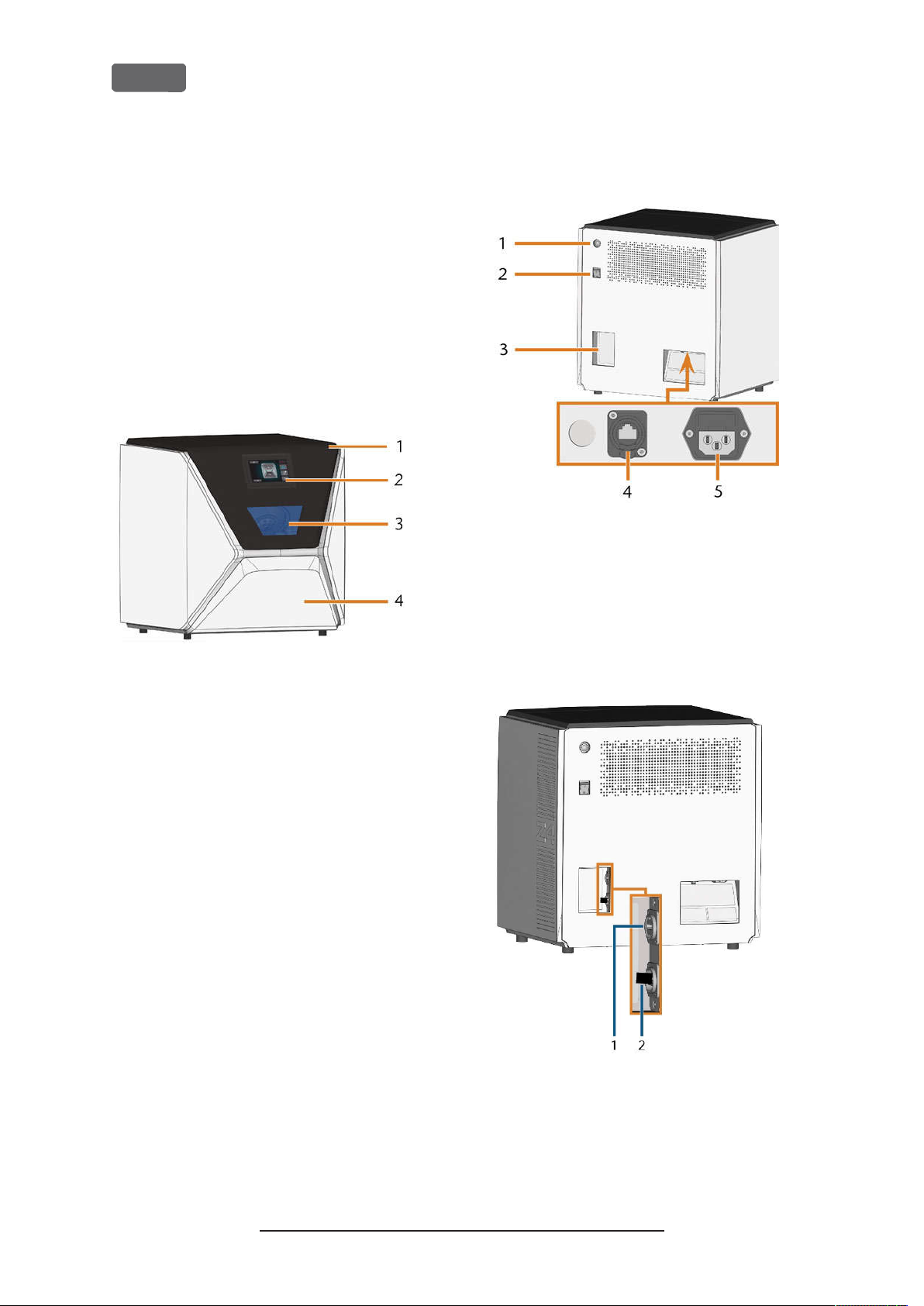
FIG. 1 – F
Rear side of the machine
FIG. 2 – R
EAR SID E OF THE MA CHINE
1.
Start button
2.
Main power switch
3.
CAM computer panel
4.
Network port (Ethernet RJ-45)
5.
Power connection
1.
Working chamber door
2.
Touchscreen for controlling the machine
3.
View window to the working chamber
4.
Multi-purpose drawer
FIG. 3 – CAM
COMPUTER PANEL
1.
HDMI 1.4b port
2.
USB 2.0 port with WiFi device
Original Operating Instructions:Z4
Version: 12/5/2018
Page 11
Color Status
Z4 – Machine overview
EN 11
Touchscreen
The screen in the working chamber door of your
machine responds to touch. You can use it to operate
the machine by selecting icons on the user interface
and to receive information about jobs, tools and the
machine status.
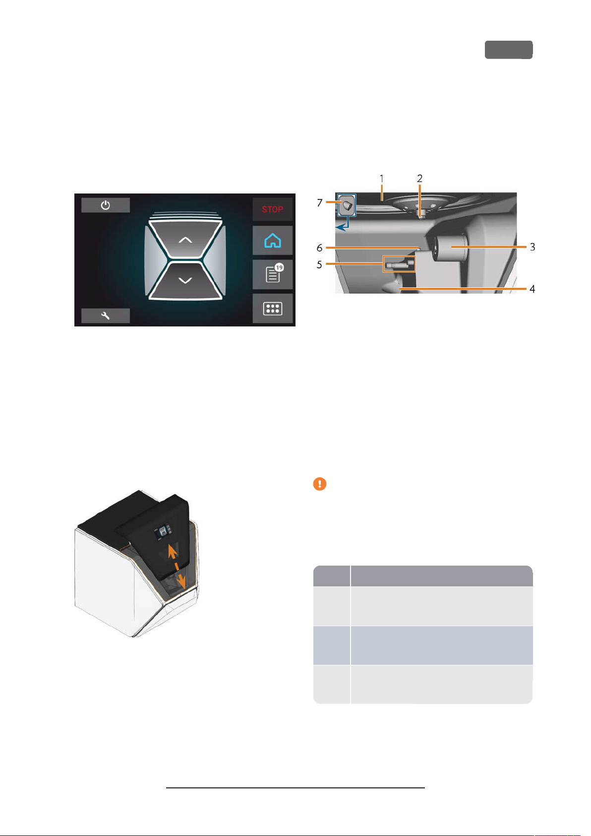
FIG. 4 – A
SECTION OF THE US ER INTERFA CE
Working chamber door
The working chamber door locks the working
chamber and protects the user from injuries during
operation.
The working chamber door is operated by electricity.
You can open and close the door via the touchscreen
or with DentalCNC. You cannot open the door when
the machine is switched off or while the axes are
moving.
Working chamber
You can mount blanks and insert tools into the
working chamber. This is where the blanks are
processed.
FIG. 6 – W
Colors of the working chamber lighting
ORKING CHAMBER
1.
Bellow/Nozzle plate
2.
Spindle with collet chuck for picking up tools
3.
Blank holder (with collet chuck); Rotational axis A
4.
Outlet for the cooling liquid
5.
Tool magazine holder
6.
Measuring key
7.
Webcam
FIG. 5 – W
ORKING CHAMBER DO OR
If the working chamber lighting is insufficient,
provide additional lighting.
The machine illuminates the working chamber in
different colors. The color will change depending on
the state of the machine. You will find the colors and
respective machine status in the following table:
White The machine is ready for operation.
You can open the working chamber door.
Blue The machine is operating.
Theworking chamber door is locked.
Red A machinemalfunction has occured.
Theworking chamber door is locked.
Original Operating Instructions:Z4
Version: 12/5/2018
Page 12
A-weighted
EN 12
Z4 – Machine overview
Multi-purpose drawer
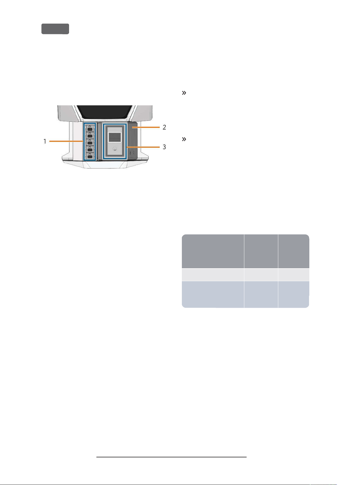
The multi-purpose drawer contains the cooling liquid
tank and up to 5 tool magazines. You can unlock the
multi-purpose drawer via the touchscreen and then
pull it out manually.
FIG. 7 – M
ULTI-PURPOSE DRAWER
1.
Space for tool magazines
2.
Cooling liquid tank
3.
Cover of the cooling liquid tank with strainer basket
Required computer hardware
software
This machine is designed for an integrated CAD/
CAM workflow which allows you to manufacture
restaurations with the following components:
The touchscreen of the machine
n
A machine internal CAM computer running
n
DentalCAM DentalCNC (manufacturing software)
An external CAD computer*running a supported
n
CAD application
*
Sound emission
The actual sound emission of the machine varies
heavily depending on the manufacturing material and
the machining conditions.
If the machine is exceptionally loud, check the following operating conditions:
Cleanliness of the blank holder
n
Condition of the tools
n
Quality of the blanks
n
If loud noise cannot be avoided, wear ear protection during machining.
Sound measurement
Measuring conditions:
n
Processed material: IPS e.max (block, C14)
Tool status: new
n
Measured value: sound pressure level (distance:
n
1m)
Measurement according to ISO 3746, survey
n
method 3
Established sound emission:
A-weighted
Operating condition
sound pres-
sure level
Processing 81.8 dB(A) 92.3dB(A)
All other operating condi-
<70 dB(A) –
tions (tool change, movement of the axes etc.)
sound
power
level
*
not provided
You can use the touchscreen for standard operation
and basic maintenance.
If you do not use an integrated CAD/ CAM workflow,
you will need to access Windows®on the CAM
computer during standard operation to directly work
with DentalCAM DentalCNC.
Original Operating Instructions:Z4
Version: 12/5/2018
Page 13
Z4 – Machine overview
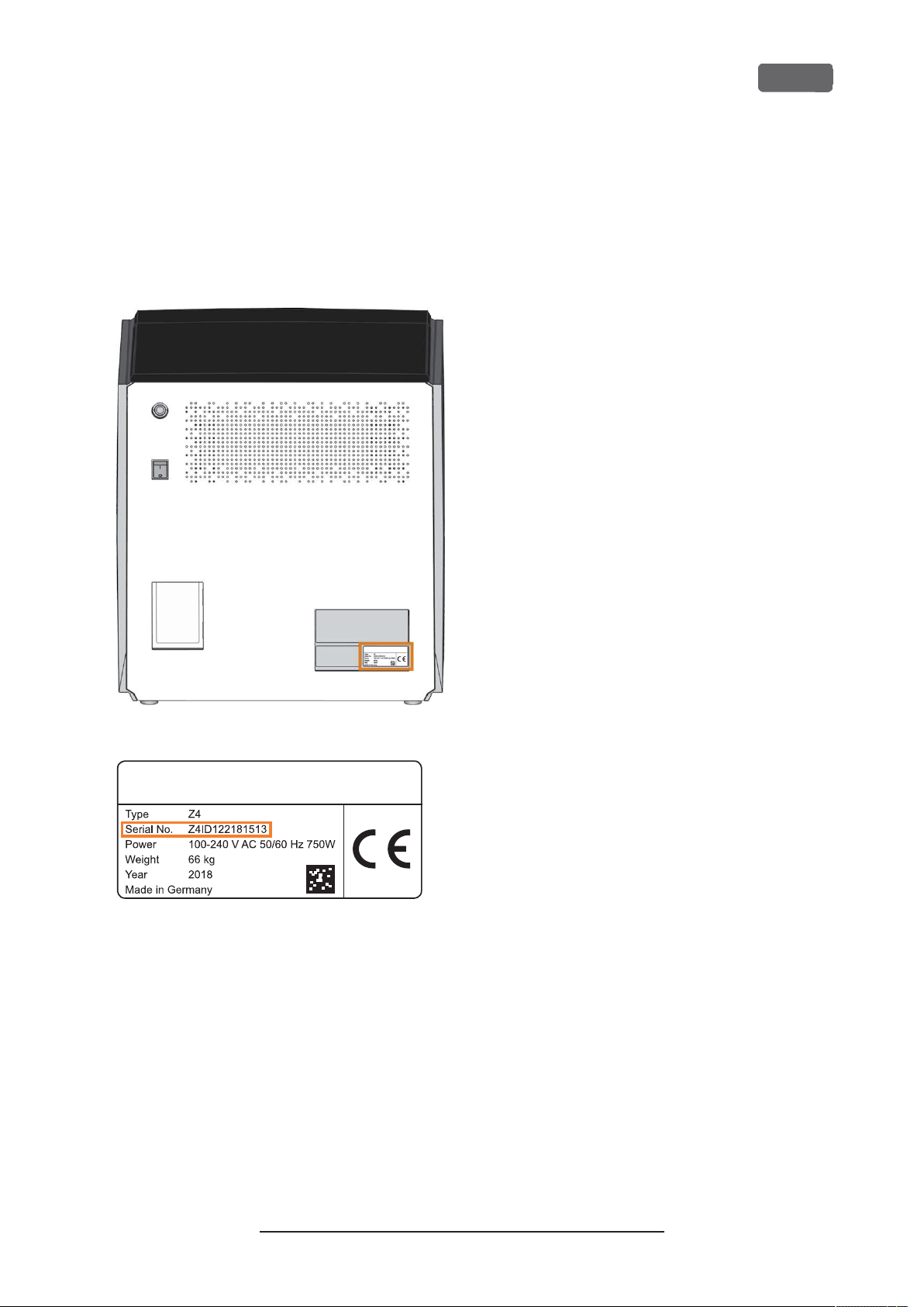
Location of the identification plate
serial number
The identification plate of the machine contains identifying information such as the serial number. You can
find the identification plate and machine serial
number at the following location:
EN 13
OCATION OF THE ID ENTIFICATIO N PL ATE(MARKED ORA NGE
FIG. 8 – L
ERIAL N UMBER ON THE IDE NTIFICATION PL ATE(MARKED
FIG. 9 – S
ORANG E
)
)
Original Operating Instructions:Z4
Version: 12/5/2018
Page 14

EN 14
Z4 – Machine overview
Technical data
Base system
Dimensions: (W/D/H):
n
Footprint: approx.400x 305 mm
Housing fully closed: approx.471x 522x 507mm
Housing fully open: approx.471x 737x 608mm
Weight: approx.66 kg
n
4-axis mechanism
n
Rotational axis A: +190° to -10°
n
Working chamber
n
Complete housing of the working chamber
Working chamber lighting with different colors to indic-
ate the machine state
Webcam for video transmissions to customer service
Integrated compressed air production
n
Permitted ambient temperature/ air moisture:
n
Ambient temperature (storage/ transport): between
-20°C and 60°C
Ambient temperature (operation): between 10°C and
32°C
Relative air moisture: max. 80, non-condensing
Spindle SFZ 170P
Asynchronous spindle rotating up to 100,000 rpm
n
Nominal power under continuous operation (S1): 170 W
n
Nominal power under uninterrupted periodic operation
n
(S6): 220 W
Peak power (P
n
Hybrid ceramic ball bearing
n
2-fold bearing
n
Pneumatic collet chuck Ø 3mm
n
Sealing air
n
Standard blank holder
For mounting blocks with round shafts
n
Maximum number of blocks per job: 1
n
n
Maximum block dimensions: 40x 20x 20mm (L/D/H)
Supports designated abutment holders
n
Tool magazine
Removable (5 provided)
n
Maximum tools in magazine: 6
n
Maximum tool length: 35 mm
n
Automatic tool change with compressed air monitoring
n
n
Automatic tool length measurement and tool breakage monitoring via a measuring key
Material allocation through color code
n
Automatic tool magazine recognition
n
): 340 W
max
Removable
Dishwasher-safe
Flow sensor for monitoring the flow of the cooling liquid
n
Connections
Power connection: 100 – 240 V AC, 50/60 Hz including
n
glass fuse T6,3A L250V
Network port
n
RJ-45
Speed: 10BASE/100BASE-TX/1000BASE-T (Auto-sensing)
Internal CAM computer
Processor:
n
Intel® Atom™ E3950
4 cores
1.60 – 2.00 GHz
RAM: 8GB DDR3L-SDRAM
n
Graphic:
n
GPU: Intel® HD Graphics 505
Display Interface: HDMI1.4b up to 3840x 2160 at
1
30Hz
LAN: Intel®I211 GbE LAN controllers (RJ-45)
n
Audio: not available
n
USB 2.0 interface with WiFi device
n
1
wired to the CAM computer panel of the machine
2
wired to the connection panel of the machine
1
2
WiFi
Standards: IEEE 802.11 ac
n
n
Data rate:
802.11 ac: downlink up to 867Mbps, uplink up to
867Mbps (20/40MHz)
802.11 a/b/g/n/ac: downlink up to 300Mbps, uplink up
to 300Mbps (20/40MHz)
Encryption:
n
64-bit WEP
128-bit WEP
WPA2-PSK
WPA-PSK
Operating frequency: 2.4 GHz/5 GHz
n
Cooling liquid system for wet machining
Cooling liquid: Drinking water
n
n
Integrated cooling liquid tank
Maximum amount of cooling liquid: 2 l
Integrated filter
Original Operating Instructions:Z4
Version: 12/5/2018
Page 15
Z4 – Installing the machine
5 Installing the machine
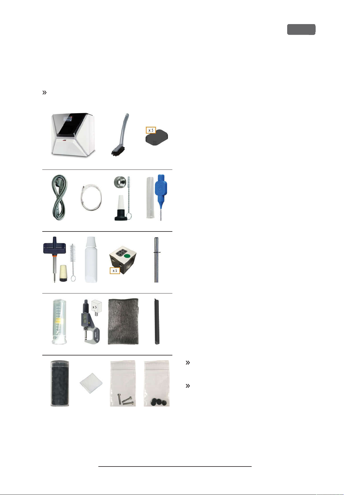
Checking the scope of delivery
Unpack the machine and ensure that you have
received the following items:
1 2 3
4 5 6 7
1.
1x Machine Z4
2.
1x Cleaning brush
3.
5x Tool magazine inserts
4.
1x Power cable
5.
1x Ethernet network cable(type: straight)
6.
1x Spindle service set
7.
1x Interdental brush(for cleaning the nozzle plate)
8.
1x Blank holder service set
9.
1x Tube of collet chuck grease (for spindle, blank
holder, tool magazine holder)
10.
5x Tool magazines (in the drawer)
11.
1x Measuring pin
12.
1x Drill bit for tool positions (2.8 mm)
13.
1x Calibration set: 1 micrometer, 5 blanks for manufacturing test and calibration specimen
14.
1 x Microfiber cloth
15.
1 x View window wiper
16.
1 x Container with activated carbon pellets
17.
1 x Fine filter
18.
3 x Fixing screw for the collet chuck of the blank
holder
19.
5 x Tool magazine caps
EN 15
8 9 10 11
12 13 14 15
16 17 18 19
Not depicted:
This document
n
1 x Carrying aid for transporting the machine
n
1 x Transport lock in the working chamber
n
1 x Supplement about removing the carrying aid
n
and transport lock
1 x Transport protection cover in the multi-pur-
n
pose drawer
n
1 x Allen key for the tool magazine release screw
1 x Allen key for the holder of the view window
n
wiper
Store the measuring pin and the calibration set
safely near the machine. Customer service will
need them for maintenance.
Keep the packaging of the machine, the carrying
aid and the transport lock for future transports.
Original Operating Instructions:Z4
Version: 12/5/2018
Page 16
EN 16
Z4 – Installing the machine
Choosing the installation site
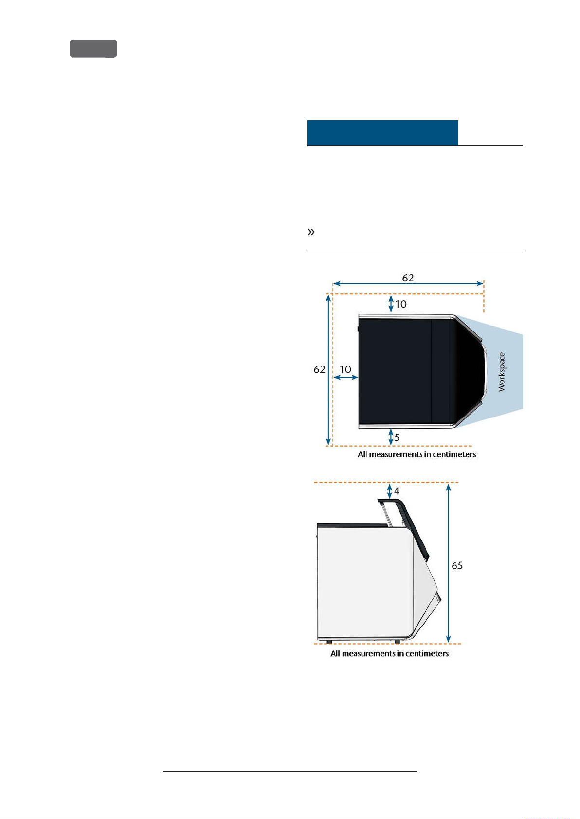
The installation site must meet the following criteria:
n
Firm and even surface, must be able to carry the
weight of the machine (66 kg)
Minimum required space: 620 x 620 x 650 mm
n
(W/D/H)
Ambient temperature (storage/ transport):
n
between -20°C and 60°C
Ambient temperature (operation): between
n
10°C and 32°C
Relative air moisture: max. 80, non-con-
n
densing
Machine location must be dust-free
n
Alternating current source with 100 – 240 V AC,
n
50/60 Hz
An operational Residual Current Device/ Ground
n
Fault Circuit Interrupter on the electric circuit of
the machine
Access to the internet and local computer net-
n
work via cable/ WiFi
Distances to maintain
NOTICE
Damaging of the machine if safety
distances are not maintained
If you do not maintain the safety distances, the
movable parts of the housing can collide with
obstacles when being opened and get damaged. If
the ventilation openings are covered, the machine
may overheat and get severely damaged.
Ensure that the following safety distances are
always maintained.
FIG. 10 – D
ISTA NCES TO MAINTAIN
Original Operating Instructions:Z4
Version: 12/5/2018
Page 17
Z4 – Installing the machine
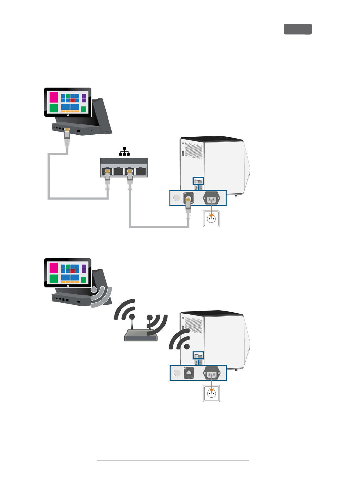
Machine installation (schema)
Wired connection
EN 17
WiFi connection
Original Operating Instructions:Z4
Version: 12/5/2018
Page 18

EN 18
Z4 – Installing the machine
Establishing the electric connection
NOTICE
Damaging of the machine through heavy
voltage fluctuations
Heavy voltage fluctuations can disrupt the control unit
and can cause system failures.
Plug the machine’s power cable in a dedicated
current circuit or ensure that no devices are connected that can cause heavy voltage fluctuation
when switched on.
If heavy voltage fluctuations cannot be avoided,
install a suitable device which protects the
machine from heavy voltage fluctuations.
NOTICE
Short-circuit hazard when the machine is
too cold
If the machine is transported from a cold environment
into a warmer environment, a short circuit may occur
caused by condensate.
Before
portation, ensure the following:
n
n
n
The machine requires a continuous power supply for
proper operation.
1.
Plug the provided power cable into the power
connection at the connection panel of the
machine.
2.
If power failures occur regularly at the installation
location or if there are frequent voltage fluctuations, install an online Uninterruptible Power
Supply (UPS).
switching on the machine after trans-
The ambient air has the allowed temperature.
The machine has the same temperature as the
ambient air. This will take
The machine is completely dry.
If a power failure occurs during job execution, the tool may break and the blank
may be destroyed.
at least
48hours.
Removing the transport lock
Before operating the machine for the first time, you
must remove the transport lock. The transport lock
prevents the spindle from getting damaged during
transport.
1.
Ensure the following:
The machine is connected to the electrical
n
source.
2.
Switch on the machine at the main power switch.
3.
Press the start button.
The machine references.
4.
Open the working chamber door by
selecting the upper arrow of the depicted icon on the touchscreen.
5.
Remove the transport lock as shown in the supplement.
Checking the tool magazines in
the drawer
After you have removed the transport lock, you should
open the multi-purpose drawer and check the tool
magazines.
1.
To unlock the multi-purpose drawer,
select the lower arrow of the depicted
icon in the
screen.
After a couple of seconds, the drawer will open.
2.
Pull the drawer open.
3.
Remove the transport protection cover from the
tool magazines.
4.
Verify that there are 5 tool magazines with different color codes in the drawer.
5.
To close the multi-purpose drawer, push it until it
locks back in place.
You will hear a clicking sound.
More information on tool magazines and
managing tools:
page41
section of the touch-
Home
Ž
Managing tools
– on
3.
Insert the plug of the cable into a socket that is
protected by a Residual Current Device/ Ground
Fault Circuit Interrupter.
Original Operating Instructions:Z4
Version: 12/5/2018
Page 19
Z4 – Installing the machine
EN 19
CAD computer network integration
The CAD/ CAM integration workflow is as follows:
1.
Prepare the machine and the CAD computer (
page 19
2.
Access the CAM computer (
3.
(Optional)Set up WiFi access for the machine
(
Ž
4.
Integrate the CAD and CAM/CNC software (
page 24
)
page 23
)
Ž
page 20
)
)
Ž
NOTICE
Danger caused by default passwords and
network intrusions
The default passwords mentioned in this public document allow everyone to access the corresponding
devices via the network and/ or the internet. This can
lead to data theft, data corruption and damaging of
the machine and other devices.
Have the network integration of the machine and
other connected devices carried out by a qualified
network and IT specialist.
Have the specialist change the default passwords
after installation and secure your network against
intrusion. Ensure that passwords are recorded and
handed to you.
Ensure that the user
signed-in at Windows®startup. Otherwise, the
machine will not be operational. You must reenable the automatic sign-in when you change the
password for this user.
Ensure that the user
istrator privileges. Otherwise, the machine will not
be operational.
Be aware that changing the passwords for the predefined user accounts may require a reconfiguration of the machine’s network connection
and the CAD/CAM integration.
For remote maintenance, you can use
TeamViewer. Start the application via the icon on
the desktop of the CAM computer.
camcomputer
camcomputer
is automatically
has admin-
Internal CAM computer
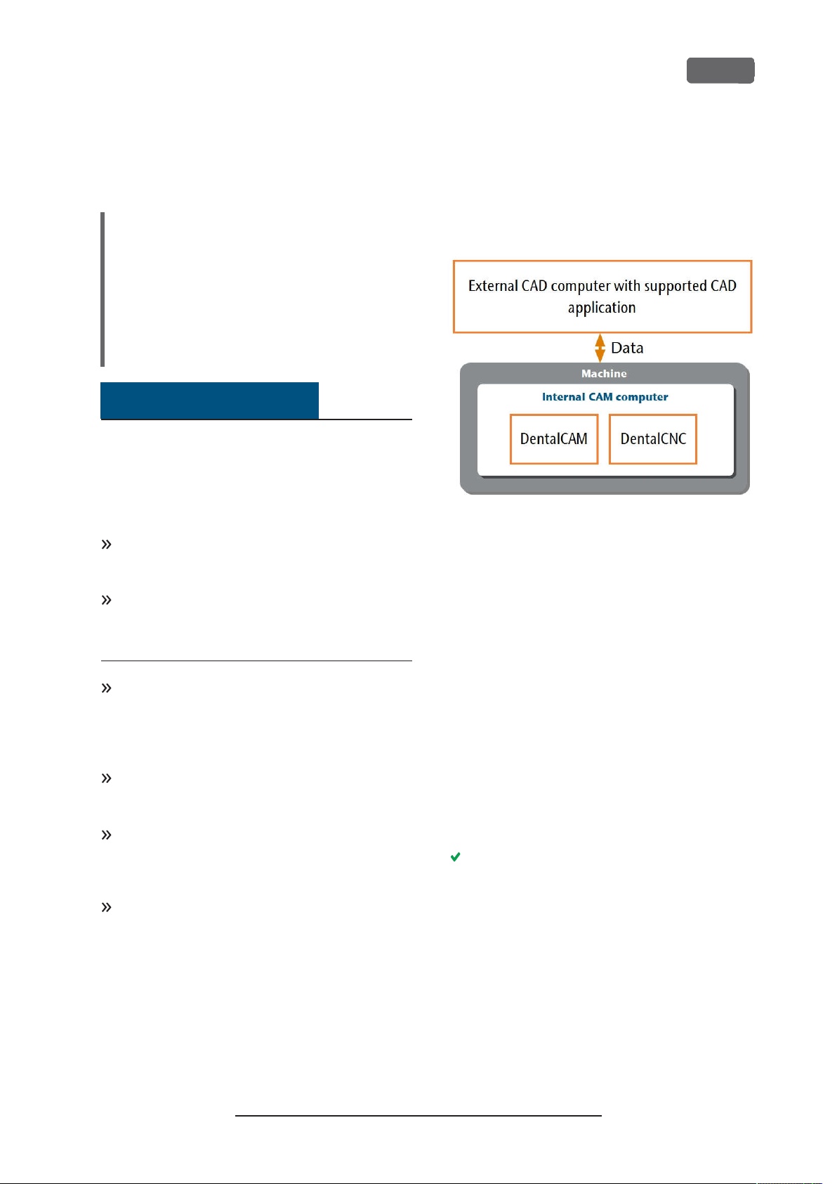
The machine is equipped with an internal CAM
computer running the manufacturing software
DentalCAM DentalCNC. Manufacturing data is trans-
Ž
ferred as follows:
FIG. 11 – D
INTEG RATION
IAG RAM
ATA TRANSFER IN CA SE OF
: D
CAD/ CAM
Preparing the machine and CADcomputer
Before you can set up the CAD/ CAM integration, you
need to prepare all hardware and software components.
1.
Shut down the machine.
2.
Install the CAD application on the CAD computer.
Ensure that the CAD application is licensed to use
the Z4 for manufacturing.
3.
Ensure that the CAD computer is configured for
network connectivity. This includes WiFi access if
desired.
4.
To connect the machine to a wired network, connect the machine and the CAD computer to the
local network with Ethernet cables. Do not directly connect the CAD computer to the machine.
If a DHCP server is available in the local network,
the integrated CAM computer will automatically
try to obtain a valid IP address.
5.
To connect the machine to a WiFi network, prepare the machine as follows.
a.
Connect the CAD computer to the Ethernet
port of the machine with an Ethernet cable.
b.
For the moment, deactivate WiFi access on
your CAD computer.
Otherwise, the CAD computer will not find
the CAM computer.
Original Operating Instructions:Z4
Version: 12/5/2018
Page 20

Access to
EN 20
6.
If a local network is not available, connect the
CAD computer to the Ethernet port of the
machine with an Ethernet cable.
7.
Ensure that the internal CAM computer of the
machine has access to the Internet.
If required, configure your network firewall
n
accordingly.
If permanent Internet access cannot be guar-
n
anteed, ensure that the machine is connected to the Internet at least once per
week.
The machine requires Internet access for
important updates.
8.
Switch on the machine at the main power switch.
Press the start button.
9.
Wait until the machine has referenced.
Z4 – Installing the machine
Accessing the CAM computer
NOTICE
Installing Microsoft®Office onto the
CAMcomputer violates the Windows
License Agreements
The CAM computer runs Windows®10 IoT Enterprise.
If you install any version of Microsoft®Office onto the
CAM computer, you will violate the Windows®License
Agreement which may result in the following:
You may lose the right to use the pre-installed
n
Windows®on the CAM computer. Without Windows®, the machine will not work.
You may become subject to civil and criminal
n
prosecution.
Never
the CAM computer.
install any version of Microsoft®Office onto
®
Once the machine is connected to the CAD computer
and the network connection is established, the CAM
computer can be accessed in 3 ways:
Access method
Remote Desktop applic-
CAM/CNC
folder?
Yes Yes
Access to Win-
dows?
ation on the CAD
computer
Connecting hardware
Yes Yes
to the machine
Windows®Explorer on
Yes No
the CAD computer
Access via the Microsoft®Remote Desktop applic-
n
ation allows you to use Windows®/ DentalCAM
DentalCNC on the CAM computer without
additional hardware.
n
You can connect additional hardware to access
the CAM computer to use Windows®/
DentalCAM DentalCNC
Accessing the DentalCAM DentalCNC install-
n
ation folder via Windows®Explorer is usually only
required for customer service.
If you do not use an integrated CAD/ CAM workflow,
you will need to access Windows®on the CAM
computer during standard operation to directly work
with DentalCAM DentalCNC.
Original Operating Instructions:Z4
Version: 12/5/2018
Page 21
Z4 – Installing the machine
EN 21
Overview CAM computer access data
Following you find the access data for the internal
CAM computer as a quick reference.
Computer name: Serial number of the machine
n
IP address: None specified, DHCP activated
n
*
Ž
Location of the identification plate serial number
on page13
Administrator user with auto sign-in at Windows
startup:
n
User:
camcomputer
n
Password:
Standard user for accessing the DentalCAM
DentalCNC installation folder, which is shared by
default:
n
User:
n
Password:
When you disconnect from the CAM
computer, never sign-out or shut down the
CAM computer. If you do, the machine will not
be operational until you restart it.
camcomputer
cnctransfer
cnctransfer
Accessing Windows®on the CAM computer
using a Remote Desktop connection
Microsoft®Remote Desktop allows you to work with
the CAM computer from another computer as if you
*
were using the CAM computer directly.
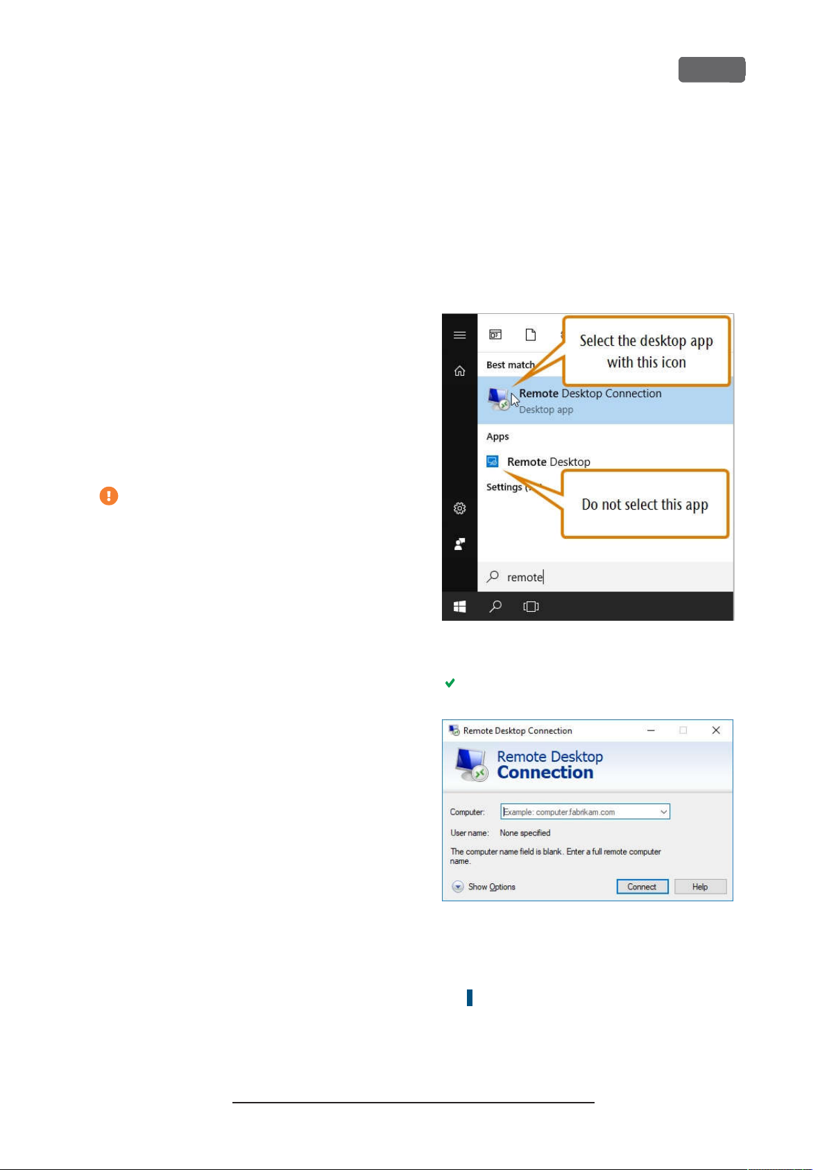
Start the
–
1.
application. Do not start the Windows®store app
Remote Desktop
®
Remote Desktop Connection
.
desktop
FIG. 12 – S
APPL ICATION
FIG. 13 – THER
2.
3.
TARTING THEREM OTEDES KTOPCONNECT ION
The
Remote Desktop Connection
EM OTEDES KTOPCONNECT ION APPLICA TION
Enter the following into the
box:
Machine serial number
Example:
Select
Z4ID212345678
[Connect]
.
window opens.
Computer
combo
Original Operating Instructions:Z4
Version: 12/5/2018
Page 22
EN 22
Z4 – Installing the machine
You are prompted to enter the login credentials.
4.
Enter the following login credentials:
n
User:
camcomputer
n
Password:
If a different default user name displays that you
cannot change, do the following:
Select
a.
Additional options display.
Select
b.
You can enter the user name given above.
Select
5.
[OK]
The desktop of the CAM computer displays in
the remote desktop application window.
Through it you can access files and start applications on the CAM computer.
camcomputer
More choices
.
Use a different account
.
.
Accessing the CAM computer via hardware
You can directly connect a monitor and/ or USB
devices to the CAM computer.
Use the ports of the CAM computer panel for this:
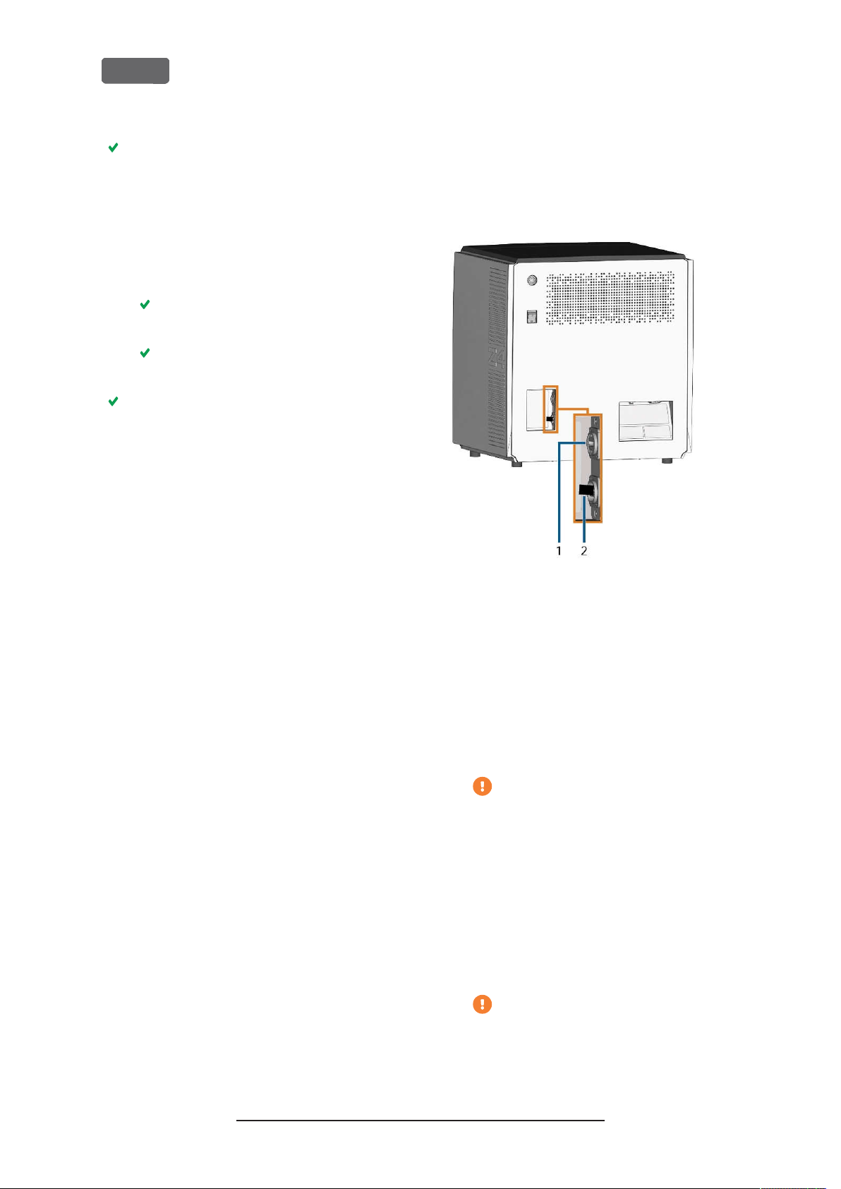
FIG. 14 – CAM
1.
2.
You can connect hardware to the internal CAM
computer as follows:
1.
Connect the monitor to the HDMI connectorof
the machine. If your monitor isnt equipped with
an HDMI cable, use an adapter.
2.
If you want to install USB devices to the CAM computer, do as follows:
COMPUTER PANEL
HDMI 1.4b port
USB 2.0 port with WiFi device
Do not connect a laptop/ tablet or similar
to the HDMI port; only connect a monitor
to the port.
a.
Remove the WiFi device from the USB port.
b.
(Optional)Connect a USB hub to the USB
port.
c.
Connect the desired USB devices to the
USB port or USB hub.
You must reconnect the WiFi device to the
USB port after removing the other
devices.
Original Operating Instructions:Z4
Version: 12/5/2018
Page 23
Z4 – Installing the machine
3.
Activate the interface of the CAM computer with
the connected input device (e.g. mouse, keyboard, touch display).
You are prompted to enter the login credentials.
4.
Enter the following login credentials:
n
User:
camcomputer
n
Password:
Press .
5.
The desktop of the CAM computer displays on
the connected display. You can access files and
start applications on the CAM computer.
camcomputer
EN 23
Accessing the DentalCAM DentalCNC
installation folder
You can access the DentalCAM DentalCNC installation folder via Windows®Explorer as follows:
1.
Start Windows®Explorer on the CAD computer.
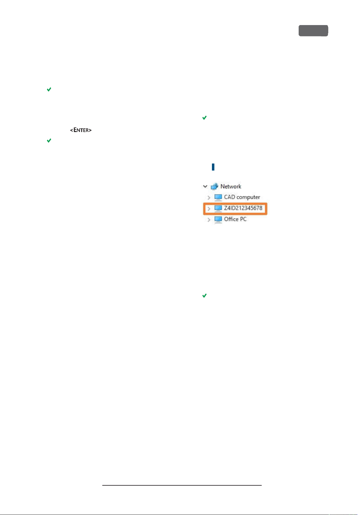
In the folder and device list in the left column,
the CAM computer name displays under the
Network
serial number of the machine (
the identification plate serial number
page13
node. The name is identical to the
).
Example:Z4ID212345678
Ž
Location of
– on
FIG. 15 – THECAM
XPL ORER
E
2.
If there is no entry for the CAM computer,
COMPUTER NAME D ISPL AYS INWINDO WS
check whether the CAD computer is correctly
integrated into the same network as the CAM
computer.
3.
Select the entry for the CAM computer.
You are prompted to enter the login credentials.
4.
Enter the following login credentials:
n
User:
cnctransfer
n
Password:
Activate the
5.
6.
Access the files on the CAM computer as you
cnctransfer
Save login credentials
option.
would with any other device.
Configuring the WiFi connection
The machine uses a pre-installed WiFi device to
connect to your access point.
1.
Ensure the following:
Your WiFi access point is operational.
n
You have fully prepared your CAD com-
n
puter and the machine as described above
(
Ž
Preparing the machine and CADcomputer
– on page19
).
®
Original Operating Instructions:Z4
Version: 12/5/2018
Page 24
EN 24
2.
Access the CAM computer via the Remote
Desktop application or direct hardware connection.
3.
Configure Windows®on the CAM computer for
WiFi connectivity:
a.
Open the Windows®network settings.
b.
Activate WiFi for the corresponding
adapter.
c.
Select a WiFi network which can be
accessed by the CAD and the CAM computer.
d.
Configure the WiFi connection as required.
4.
If you used the Remote Desktop application to
configure the CAM computer, do the following:
a.
Reactivate WiFi access on your CAD computer.
b.
Remove the Ethernet cable that connects
your CAD computer with the machine.
Z4 – Installing the machine
Integrating the CAD with the CAM/ CNC
software
The integration details depend on the used CAD
application. In addition, you must prepare the internal
CAM computer accordingly.
In the following, we assume that your
computers are not part of a Windows®domain.
If they are, you need to take this into consideration when following the instructions.
Preparing the CAM computer
The following instructions apply independently of the
used CAD application.
1.
Access Windows®on the CAM computer (
Accessing Windows® on the CAM computer using a
Remote Desktop connection
2.
Switch to DentalCNC.
Open the DentalCNC
3.
this, select the following icon in the main icon
bar:
– on page21
Application settings
Ž
).
. For
Open the
4.
following icon in the lower icon bar:
Locate the
5.
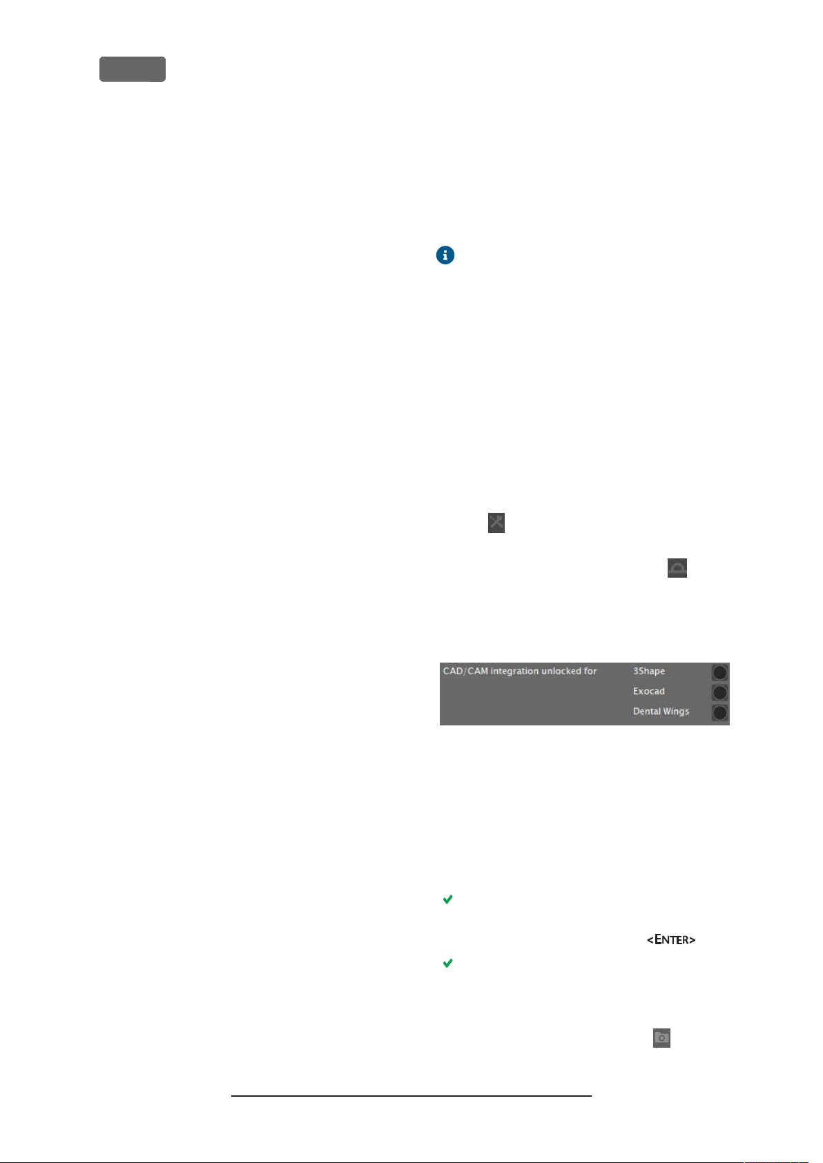
label. To the right of this label, you will find a list
of the supported CAD applications.
FIG. 16 – T
INTEG RATION S
6.
Have the unlock code that you received for your
CAD application readily available. If the unlock
code is missing, contact customer service of the
machine.
7.
Activate the option for the desired CAD application.
A window opens. You are prompted to enter the
unlock code for the selected CAD application.
Enter the unlock code and press .
8.
Machine data
CAD/CAM integration unlocked for
HE OPTIONS FOR UNL OCKING THE
view. For this, select the
CAD/ CAM
The current window closes. If the code was valid,
the integration for the selected CAD application
is unlocked.
Open the
9.
lowing icon in the lower icon bar:
Original Operating Instructions:Z4
Version: 12/5/2018
General settings
. For this, select the fol-
Page 25

Z4 – Installing the machine
Activate the
10.
option.
Activate the
11.
12.
If you want to change the language of the
DentalCNC user interface and the touchscreen of
the machine from English to another language,
do the following:
a.
b.
CAD/CAM integration activated
Integrated CAM computer
Select the desired language from the
drop-down list.
guage
Quit and restart DentalCNC.
option.
Lan-
EN 25
TRIOS Design Studio
This CAD application uses the standard DentalCAM
folder for sending objects to the machine.
Integration overview:
1.
Map a new network drive on the CAD computer
to the DentalCAM installation folder on the
internal CAM computer.
The required user account and network sharing
settings have already been configured on the
CAM computer.
2.
Store the network drive letter in TRIOS Design
Studio.
The integration in detail:
1.
Access the CAD computer.
2.
Access the DentalCAM DentalCNC installation
folder (
installation folder
Ž
Accessing the DentalCAM DentalCNC
– on page23
).
FIG. 17 – T
XPL ORER
E
3.
4.
5.
6.
7.
8.
9.
HE INSTALLATION FOL DER DISPLA YING INWINDO WS
Right-click onto the installation folder. From the
context menu, select
The
Map network drive
(Optional)From the
the desired drive letter for the new network
drive.
Record the drive letter for the network drive.
Activate the
Select
You have mapped the folder to a network drive.
Open TRIOS Design Studio.
In the menu bar, select
menu, select the
next page
Reconnect at sign-in
[Finish]
.
).
Map network drive…
window opens.
drop-down list, select
Drive
. In the drop-down
More
Ž
Settings
icon (
option.
Fig. 18 –
®
on the
Original Operating Instructions:Z4
Version: 12/5/2018
Page 26
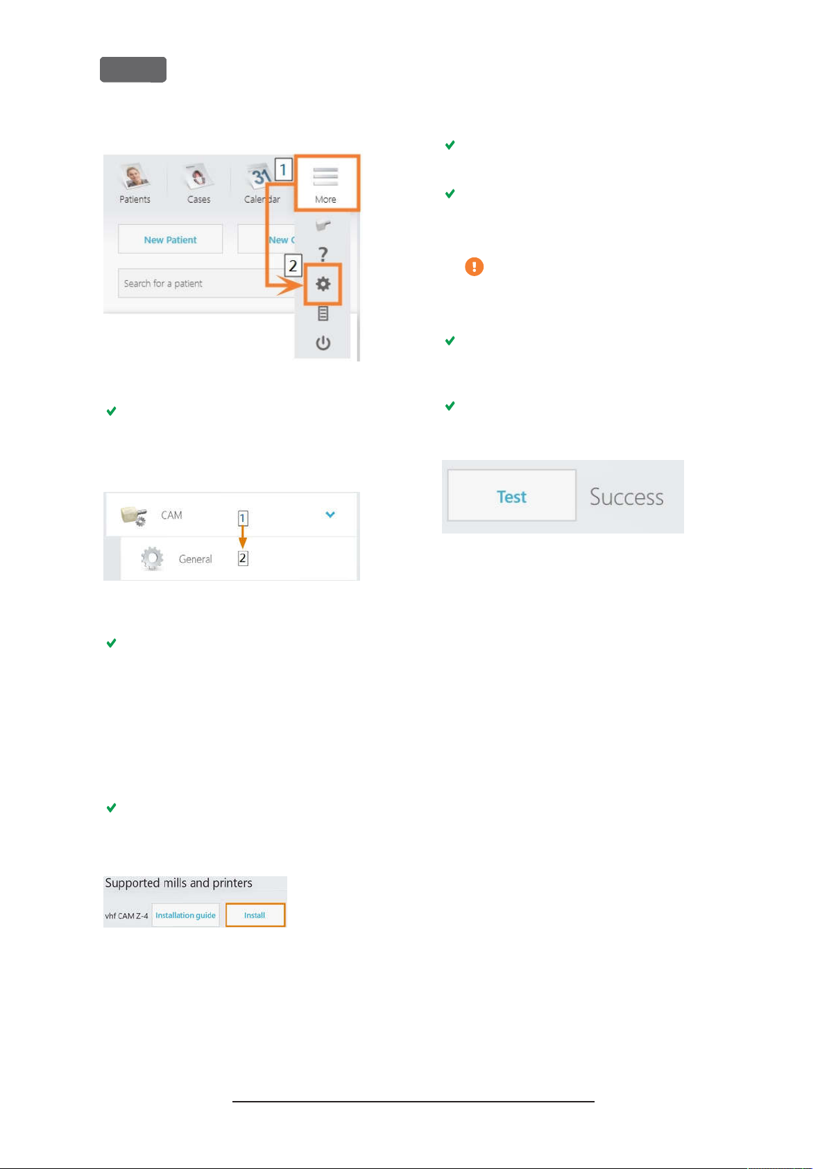
EN 26
Z4 – Installing the machine
FIG. 18 – O
PENING THE S ETTING S IN
The settings menu displays.
In the settings menu, open the
10.
In the sub-menu, select
11.
TRIOS D
General
ESIGNSTUDIO
sub-menu.
CAM
.
15.
The
Connecting to your vhf Z4
Select
[Select CAM folder]
window opens.
.
A file browser opens.
16.
In the file browser, select the network drive to
which you mapped the installation folder.
Do not select the
CNCTransfer
within the installation folder.
17.
Select
[Select folder]
.
The file browser closes. The Z4 is now listed in
the
Installed machines
In the line for the Z4, select
18.
If the CAM folder is set correctly,
to the right of the
FIG. 21 – THEZ4
ESIGNSTUDIO
D
HAS BEEN SUCCESS FUL LY AD DED TO
[Test]
section.
[Test]
button.
.
Success
folder
displays
TRI OS
FIG. 19 – O
TUDIO
S
PENING THE
CAM
SETTINGS IN
TRIOS D
ESIGN
The general CAM settings display on the right
side.
12.
Locate the
a.
Installed machines
Check if the Z4 is already listed in this sec-
section.
tion.
If the Z4 is already listed, select
b.
Confirm your choice.
Locate the
13.
Supported mills and printers
The Z4 must be listed in this section. If it isnt,
you may need to obtain a license from 3shape for
the Z4.
FIG. 20 – THES
D
ESIGNSTUDIO
In the line for the Z4, select
14.
UPPORT ED MILLS AND PRINT ERS SECTION IN
[Install]
. Confirm
your choice.
[Remove]
section.
TRIOS
19.
Save your changes in TRIOS Design Studio.
Restart the application.
.
Original Operating Instructions:Z4
Version: 12/5/2018
Page 27

Z4 – Installing the machine
EN 27
exocad ChairsideCAD
This CAD application uses a designated shared data
folder on the CAM computer for sending jobs to the
machine. The folder is already created and shared at
delivery.
Folder path on the CAM computer:
C:\CADshare\DentalNestingObjToMDW
is the local hard drive on the CAD computer.
C:
After integration, the
ible from the CAD computer via a network drive.
Integration overview:
1.
Download the integration script from the following internet address to the CAD computer:
CADshare
folder will be access-
dentalportal.info/downloads
2.
Run the script on the CAD computer. Enter the
required information.
3.
Store the path to the shared data folder on the
CAM computer in DentalCNC.
4.
Store the path to the shared data folder on the
CAD computer in exocad ChairsideCAD.
The integration in detail:
Configuring the CAD computer
1.
Access the CAD computer.
2.
Open an internet browser.
3.
Enter the following address into the address bar:
dentalportal.info/downloads
Scroll down until you reach the
4.
5.
Download the CAD/CAM integration script to the
CAD computer.
The script is stored on the CAD computer inside a
ZIP file.
6.
Unpack the ZIP file (e.g. to the Desktop).
The script file is stored under the following
name:
Z series
section.
Install_CADshare.bat
7.
Run the script.
A window opens. The script prompts you to
enter the machine serial number.
Enter the machine serial number. Press .
8.
Ž
Location of the identification plate serial
number
– on page13
The following happens:
a.
A network drive is mapped to the shared
data folder on the CAM computer.
For this, the first available drive letter on the CAD
computer is used.
Example: If Z is the first available drive letter,
you will be able to access the shared data
folder on the CAM computer by opening the
drive on the CAD computer.
Z:
b.
The login credentials for the network share
and remote desktop access are stored on the
CAD computer.
9.
Record the drive letter for the network drive.
You will need this drive letter later.
10.
Press any key.
The current window closes. The script has finished.
Setting up DentalCNC
1.
Access the CAM computer.
2.
Switch to DentalCNC.
Open the DentalCNC
3.
this, select the following icon in the main icon
bar:
Open the
4.
lowing icon in the lower icon bar:
5.
Check if the following folder path displays under
the
label:
General settings
CAD/CAM integration: Data transfer folder
Application settings
. For this, select the fol-
C:\CADshare\DentalNestingObjToMDW
If it doesn’t, do the following:
a.
To store the data transfer folder in
DentalCNC, select the depicted
icon to the right of the
CAD/CAM
integration: Data transfer folder
A window for selecting the folder opens.
b.
From the drop-down list, select the drive letterc:.
c.
Select the following folder:
CADshare\DentalNestingObjToMDW
d.
Select the depicted icon.
The selected folder displays below the
. For
label.
Original Operating Instructions:Z4
Version: 12/5/2018
Page 28

EN 28
Z4 – Installing the machine
CAD/CAM integration: Data transfer folder
Setting up exocad ChairsideCAD
1.
In Windows®Explorer, open the exocad ChairsideCAD folder.
Change into the
2.
3.
Open the following file with a text editor:
config
folder.
settings-chairside.xml
4.
Inside the file, find the following expression
(“tag”):
<NestingInterop2TemporaryFolder>
Directly behind the expression, you will find the
exocad output path.
5.
Replace the output path with the letter of the network drive that you recorded followed by a colon
(:).
Example: You recorded the drive letterZ. The
expression in the XML file must be (without
line breaks):
<NestingInterop2TemporaryFolder>
Z:
</NestingInterop2TemporaryFolder>
6.
Save and close the XML file.
label.
Dental Wings Chairside CAD
This CAD application uses a designated shared data
folder on the CAM computer for sending jobs to the
machine. The folder is already created and shared at
delivery.
Folder path on the CAM computer:
C:\CADshare\DentalNestingObjToMDW
is the local hard drive on the CAD computer.
C:
After integration, the
ible from the CAD computer via a network drive.
Integration overview:
1.
Download the integration script from the following internet address to the CAD computer:
CADshare
folder will be access-
dentalportal.info/downloads
2.
Run the script on the CAD computer. Enter the
required information.
3.
Store the path to the shared data folder on the
CAM computer in DentalCNC.
4.
Store the path to the shared data folder on the
CAD computer in Dental Wings Chairside CAD.
The integration in detail:
Configuring the CAD computer
1.
Access the CAD computer.
2.
Open an internet browser.
3.
Enter the following address into the address bar:
dentalportal.info/downloads
Scroll down until you reach the
4.
5.
Download the CAD/CAM integration script to the
CAD computer.
The script is stored on the CAD computer inside a
ZIP file.
6.
Unpack the ZIP file (e.g. to the Desktop).
The script file is stored under the following
name:
Z series
section.
Install_CADshare.bat
7.
Run the script.
A window opens. The script prompts you to
enter the machine serial number.
Enter the machine serial number. Press .
8.
Ž
Location of the identification plate serial
number
– on page13
Original Operating Instructions:Z4
Version: 12/5/2018
Page 29
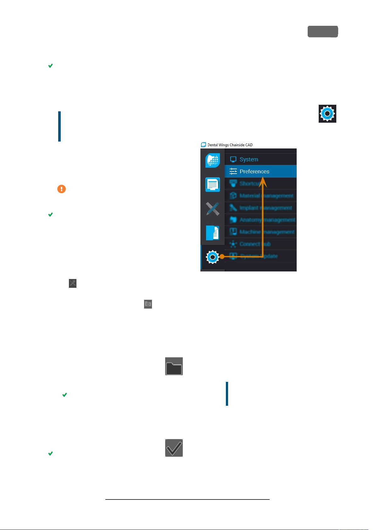
Z4 – Installing the machine
EN 29
The following happens:
a.
A network drive is mapped to the shared
data folder on the CAM computer.
For this, the first available drive letter on the CAD
computer is used.
Example: If Z is the first available drive letter,
you will be able to access the shared data
folder on the CAM computer by opening the
drive on the CAD computer.
Z:
b.
The login credentials for the network share
and remote desktop access are stored on the
CAD computer.
9.
Record the drive letter for the network drive.
You will need this drive letter later.
10.
Press any key.
The current window closes. The script has finished.
Setting up DentalCNC
1.
Access the CAM computer.
2.
Switch to DentalCNC.
Open the DentalCNC
3.
this, select the following icon in the main icon
bar:
Application settings
. For
CAD/CAM integration: Data transfer folder
Setting up Dental Wings Chairside CAD
1.
On the CAD computer, open Dental Wings Chairside CAD.
2.
Open the settings by selecting the
depicted icon in the left column.
Select
3.
FIG. 22 – O
CAD
Preferences
PENING THE S ETTING S INDENTA LWING SCHAIRSID E
.
label.
Open the
4.
lowing icon in the lower icon bar:
5.
Check if the following folder path displays under
the
label:
General settings
CAD/CAM integration: Data transfer folder
. For this, select the fol-
C:\CADshare\DentalNestingObjToMDW
If it doesn’t, do the following:
a.
To store the data transfer folder in
DentalCNC, select the depicted
icon to the right of the
integration: Data transfer folder
A window for selecting the folder opens.
b.
From the d rop-down list, select the drive letterc:.
c.
Select the following folder:
CAD/CAM
label.
CADshare\DentalNestingObjToMDW
d.
Select the depicted icon.
The selected folder displays below the
Open the
4.
5.
Enter the network path to the shared data folder
into the
VHF Z4 Output directory
Select
a.
b.
Access the mapped network drive by selecting the drive letter that you recorded.
c.
On the network drive, select the following
folder:
Milling
[…]
menu.
input field.
.
DentalNestingObjToMDW
Example: If Z is the network drive letter,
the network path is:
Z:\DentalNestingObjToMDW
Original Operating Instructions:Z4
Version: 12/5/2018
Page 30
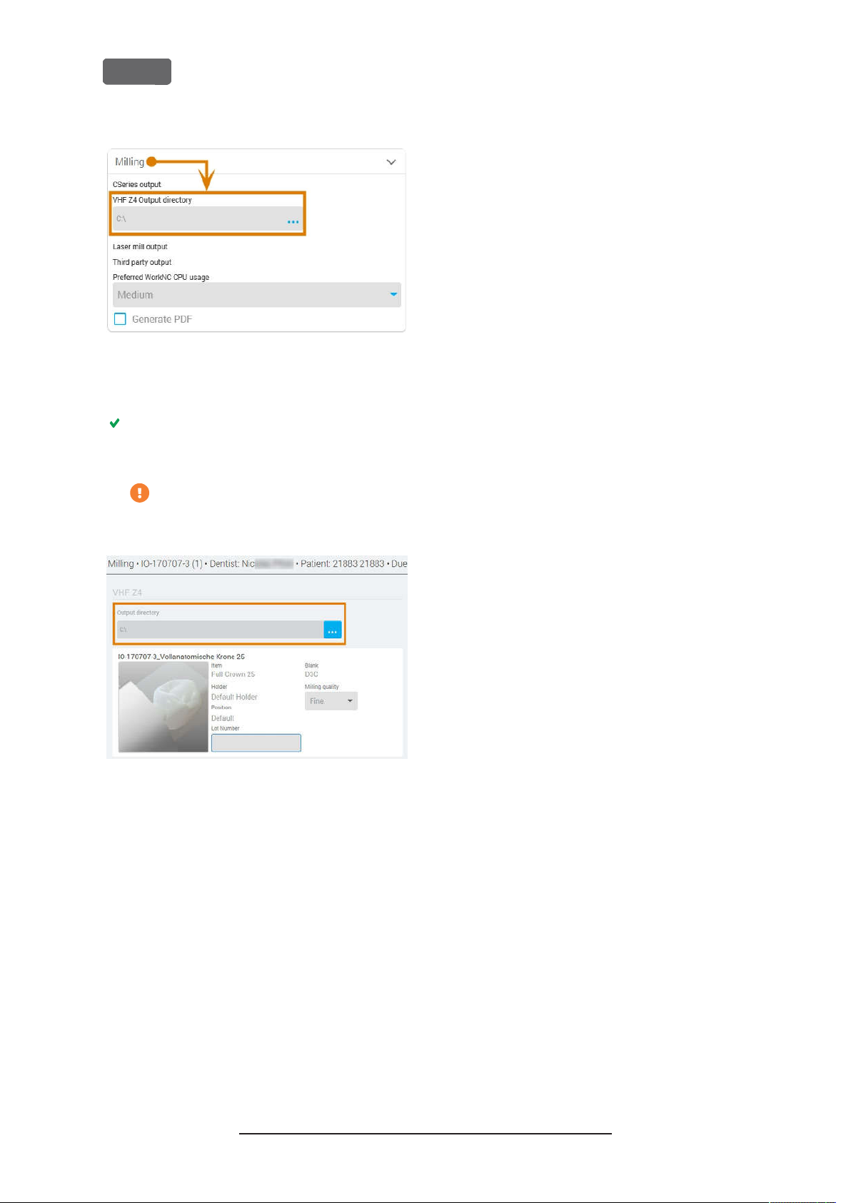
EN 30
Z4 – Installing the machine
FIG. 23 – S
HAIRSID E
C
6.
PECIF YING THE OUTPUT PATH INDENTA LWINGS
CAD
Save your changes.
From now on, Dental Wings Chairside CAD automatically suggests exporting dental objects into
the specified folder.
Do not manually change the folder or else
the CAM computer will not find the jobs.
FIG. 24 – I
DIS PLA Y A T THE END OF A WORKFLO W
N THE MA RKED INPUT FIEL D,THE SPECIFIED FOLDER WIL L
Original Operating Instructions:Z4
Version: 12/5/2018
Page 31

Z4 – Operation: Preparing jobs
EN 31
6 Operation: Preparing
jobs
Before you can machine blanks, you need to prepare
the machine. The corresponding jobs must have been
transferred to the machine so that they display on the
touchscreen.
NOTICE
Damaging of the internal CAM computer
If you switch off the machine or disconnect it from the
electrical source while the Windows®operating
system on the internal CAM computer is shutting
down or updating, the CAM computer may get
damaged. Without the CAM computer, the machine
will not be operational.
Updates may occur when you switch on the machine
and when you shut it down via the touchscreen. In
case of a major Windows®update, the update process
may take several hours.
Always
screen
switch or disconnecting it from the electrical
source.
Always
shut down before pressing the main power switch
or disconnecting the machine from the electrical
source.
When you switch on the machine,
until the machine is fully operational.
switch it off or disconnect it from the electrical
source while it is starting up.
shut down the machine via the touch-
before
switching it off at the main power
wait until the machine has completely
always
Do not
wait
Starting the machine
NOTICE
Short-circuit hazard when the machine is
too cold
If the machine is transported from a cold environment
into a warmer environment, a short circuit may occur
caused by condensate.
Before
portation, ensure the following:
n
n
n
1.
Ensure that the machine is properly installed.
2.
Switch on the machine at the main power switch.
3.
Press the start button.
The machine indicates on the touchscreen that it
is starting up.
switching on the machine after trans-
The ambient air has the allowed temperature.
The machine has the same temperature as the
ambient air. This will take
The machine is completely dry.
at least
48hours.
FIG. 25 – T
4.
HE MA CHINE IS STARTING UP
Wait until the machine has started up. This usually
takes up to 2 minutes, but can take significantly
longer in case of a Windows®update.
The following happens:
a.
The touchscreen indicates that the internal
CAM computer is connecting to the touchscreen.
Original Operating Instructions:Z4
Version: 12/5/2018
Page 32
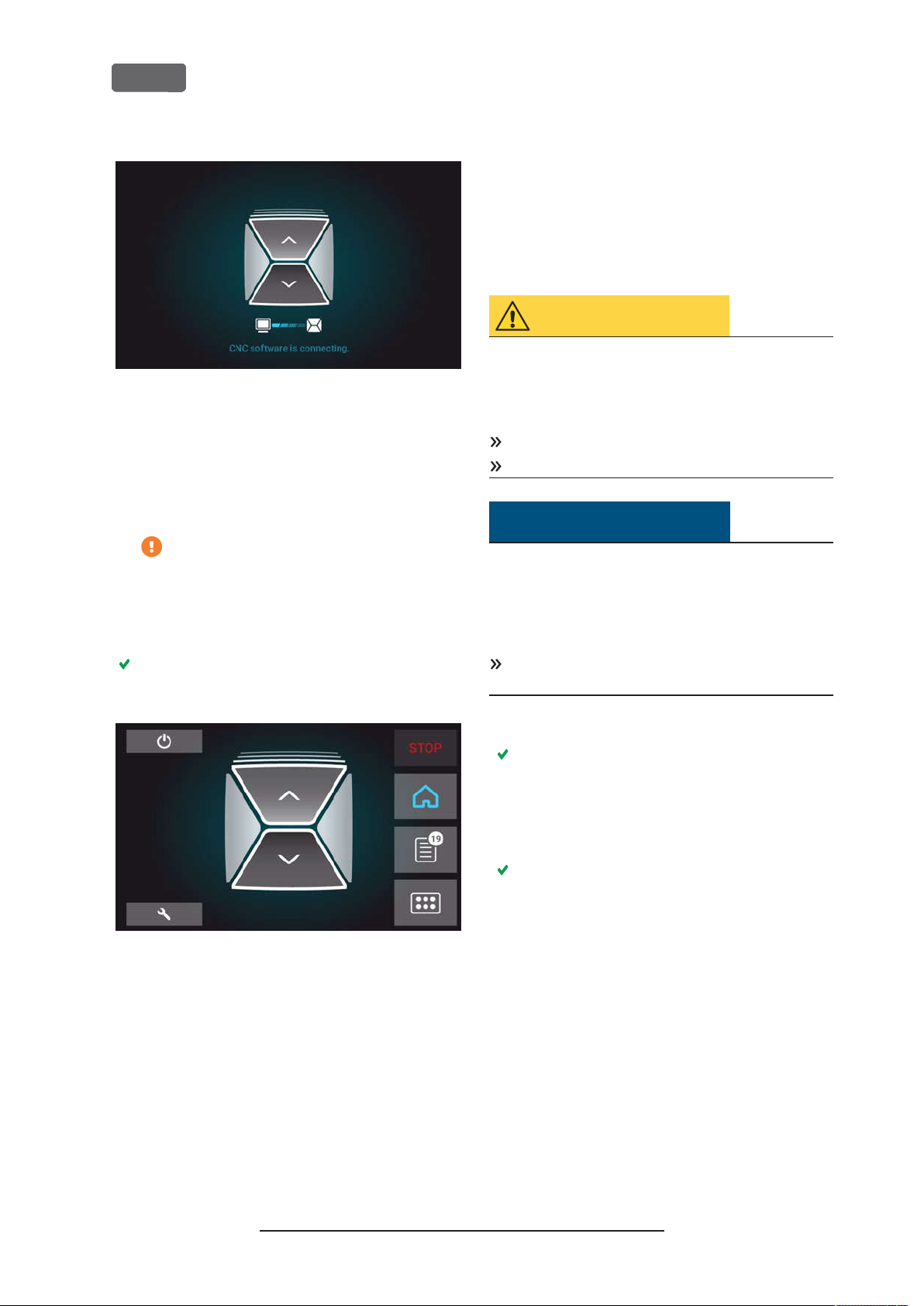
EN 32
FIG. 26 – T
TOUCHSCREEN
5.
HE INTERNA L
b.
After a few seconds, the connection is established.
c.
The machine references.
d.
The working chamber is illuminated in white.
The machine will not reference if the
working chamber door is open.
If the working chamber door is open, confirm the
respective dialog on the touchscreen to close the
door.
After the machine has referenced, the
tion displays on the touchscreen.
COMPUTER IS CONNECTING TO THE
CAM
Home
sec-
Z4 – Operation: Preparing jobs
Starting the machine with a tool in
the collet chuck
Under some circumstances like a power outage, there
can be a tool in the collet chuck of the spindle when
you start the machine. You need to remove the tool
from the collet chuck before you can use the machine.
CAUTION
Danger of cuts and burns when touching
tools with your bare hands
If you handle tools on the cutting surface, you may be
injured. As the tool may be very hot, you may also
suffer from skin burns.
Only touch tools at their shank.
When handling tools, wear protective gloves.
NOTICE
Machine damage if you do not remove the
tool
If the tool remains in the spindle after you have
confirmed the message, it will collide with machine
parts such as the measuring key and severely damage
them.
Always
start the machine with a tool in the collet chuck.
follow the instructions below when you
FIG. 27 – T
If the touchscreen displays that there is a tool in the
collet chuck which needs to be removed:
the machine with a tool in the collet chuck
If the touchscreen displays that a software update is
available:
page68
HE TOUCHSCREEN A FTER REFE RENCING
Ž
Updating the software and firmware
Ž
Starting
– see below
– on
1.
Start the machine.
The touchscreen displays that there is a tool in
the collet chuck. The working chamber door
opens.
2.
Hold the tool in the collet chuck in place.
3.
Confirm the current message.
The following happens:
a.
The collet chuck opens.
b.
The current dialog window closes.
c.
A dialog window opens.
4.
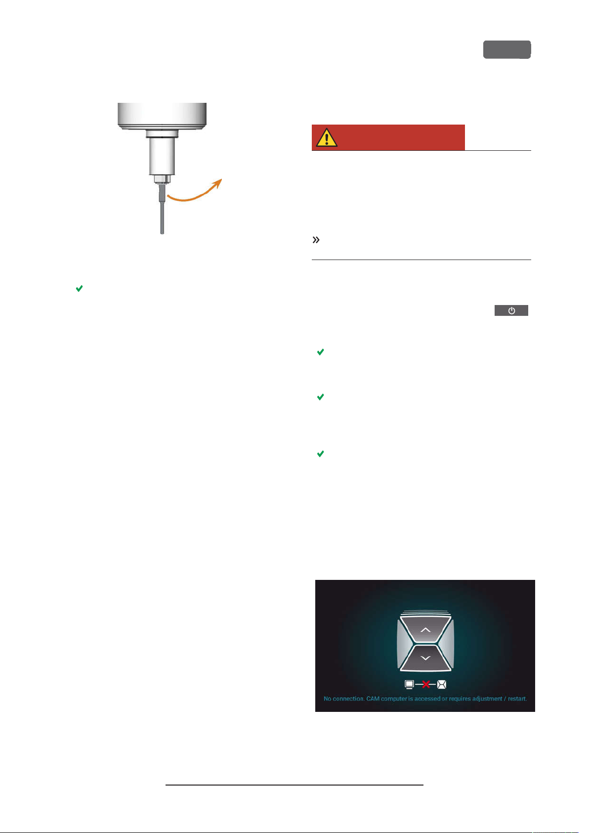
Remove the tool from the collet chuck.
Original Operating Instructions:Z4
Version: 12/5/2018
Page 33
Z4 – Operation: Preparing jobs
FIG. 28 – R
5.
EMOV ING THE TOOL FROM THE COLLET CHUCK
Confirm the current message.
The working chamber door closes.The machine
is ready for operation.
EN 33
Shutting down the machine
DANGER
Danger of an electric shock if unplugging
the power cable before switching off the
machine
If you unplug the power cable while the main power
switch is still in “ON” position, residual voltage in the
power cable may cause you to suffer from an electric
shock.
Before
the machine at the main power switch.
You can shut down the machine when it is not
processing.
Select the depicted icon in the
1.
section of the touchscreen (
touchscreen
unplugging the power cable, switch off
Home
Ž
The sections of the
– on page36
).
The machine shuts down.
2.
Wait until the touchscreen is switched off and the
machine has completely shut down.
You can restart the machine by pressing the start
button of the machine.
3.
(Optional)Switch off the machine at the main
power switch.
The machine is no longer powered. Information
on restarting it:
page31
.
Ž
Starting the machine
– on
If there is no connection to the
CAM computer
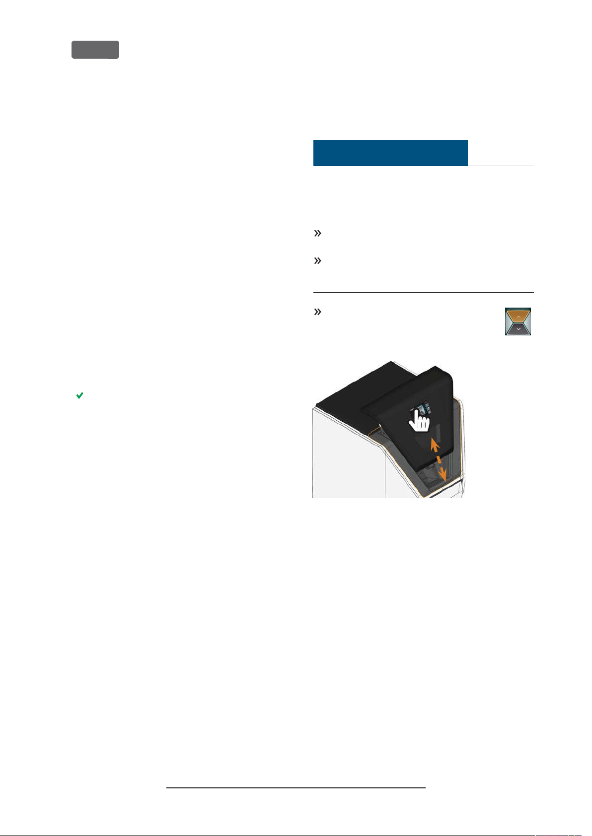
If the connection to DentalCNC on the CAM computer
gets lost or cannot be established at startup, the touchscreen displays the following image:
FIG. 29 – T
CONNECTION TODENTA L
HE TOUCHSCREEN IN DICATING THAT THERE IS NO
Original Operating Instructions:Z4
Version: 12/5/2018
CNC
Page 34
EN 34
Z4 – Operation: Preparing jobs
The connection to DentalCNC may fail for the
following reasons:
The start of DentalCNC is delayed because of
n
Windows®updates.
The CAM computer encountered a hardware/
n
software problem.
The CAM computer is not correctly configured.
n
To (re-)establish the connection, you can do the
following:
1.
Try to access the CAM computer via a remote
desktop connection (
CAM computer using a Remote Desktop connection
on page21
2.
If you cannot establish a remote desktop connection, access the CAM computer by connecting additional hardware to it (
CAM computer via hardware
3.
Check if Windows®is installing updates. In this
case, wait until the updates have been installed.
4.
If DentalCNC is no longer runningproperly,
restart Windows®.
).
Ž
Accessing Windows® on the
Ž
Accessing the
– on page22
).
Opening closing the working
chamber door
NOTICE
Damaging of the machine by operating the
working chamber door inappropriately
The working chamber door is operated by electricity.
If you manually open or close the working chamber
door, you can damage the machine.
Manually open or close the working chamber door
only in case of an emergency.
–
Before
chamber door, read the respective information in
the chapter Operation: Executing jobs.
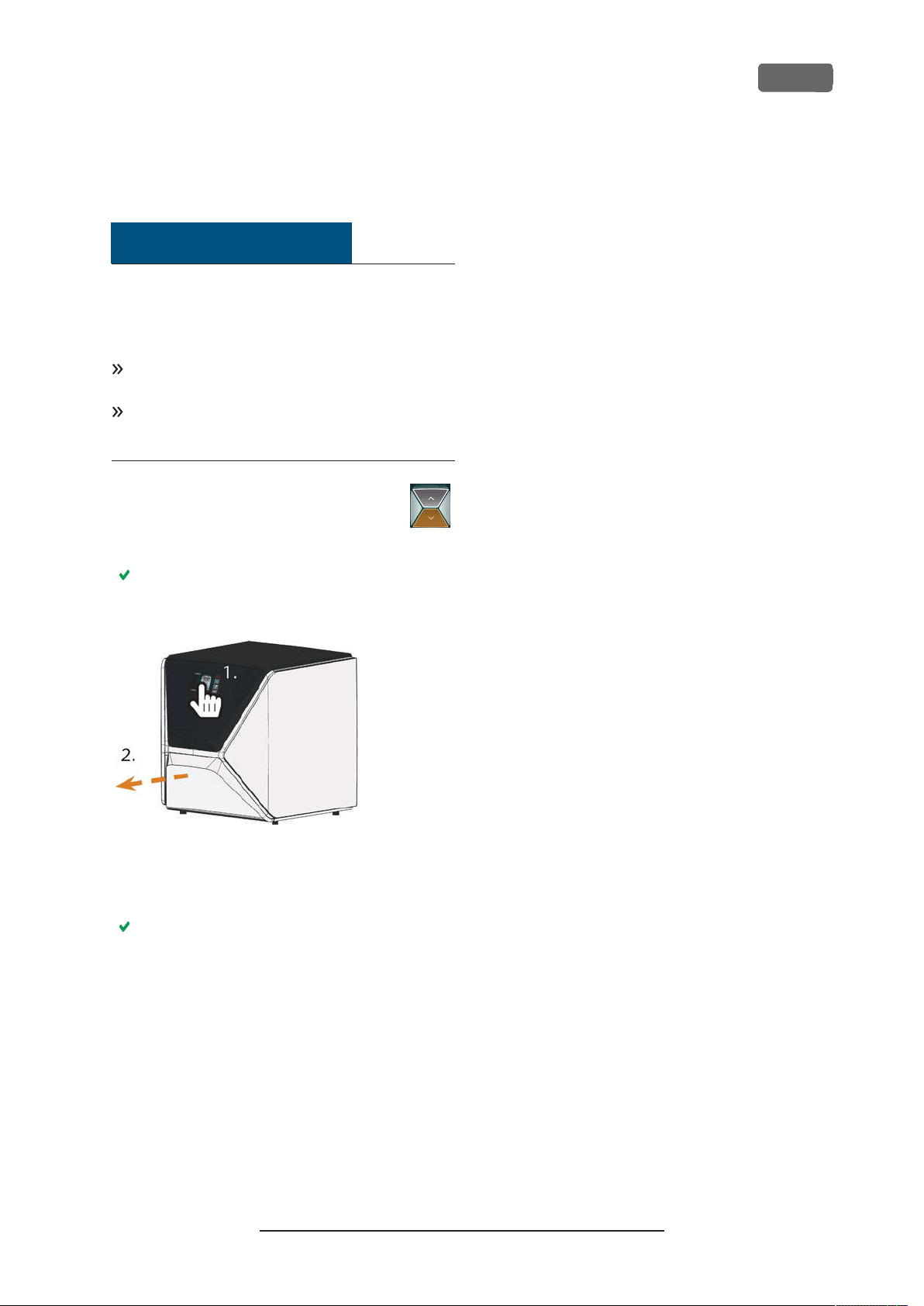
To open or close the working chamber
door, select the upper arrow of the depicted icon on the touchscreen.
you manually open or close the working
DentalCNC should automatically launch shortly
after Windows®startup and establish the connection to the machine.
5.
If Windows®is no longer running properly, do the
following:
a.
Switch off the machine at the main power
switch.
b.
Wait 10 seconds.
c.
Switch on the machine at the main power
switch.
6.
If Windows®and DentalCNC seem to be running
fine, check if the network configuration and
CAD/CAM integration is set up according to the
installation instructions (
work integration
7.
If the problem persists, contact customer service.
– on page19
Ž
CAD computer net-
).
FIG. 30 – O
PENINGCLOSING THE WORKING CHAMBER D OOR
Original Operating Instructions:Z4
Version: 12/5/2018
Page 35
Z4 – Operation: Preparing jobs
Opening closing the multi-purpose drawer
NOTICE
Damaging of the machine by operating the
multi-purpose drawer inappropriately
If you open the multi-purpose drawer by force, if you
do not maintain it properly or if you do not remove
leaked cooling liquid, the machine may get damaged.
Before you pull out the multi-purpose drawer,
unlock it.
Check regularly if the area below the cooling liquid
tank is dry and remove leaked cooling liquid immediately.
1.
To unlock the multi-purpose drawer,
select the lower arrow of the depicted
icon in the
screen.
section of the touch-
Home
EN 35
After a couple of seconds, the drawer will open.
2.
Pull the drawer open.
FIG. 31 – O
3.
PENING THE MUL TI-PURPOSE DRAWER
To close the multi-purpose drawer, push it until it
locks back in place.
You will hear a clicking sound.
Original Operating Instructions:Z4
Version: 12/5/2018
Page 36
EN 36
The user interface on the touchscreen
With the touchscreen, you can operate the main functions of the machine:
Controlling basic machine functions
n
Managing and executing jobs
n
Viewing the progress of the current job
n
Managing tools
n
Handling maintenance tasks
n
Functions of the user interface may be added
or changed via software and firmware
updates. If some functions are not available on
your machine, you may need to update
DentalCAM DentalCNC and/ or the firmware (
Ž
Updating the software and firmware
on page68
).
Visit dentalportal.info for information on
new or updated features.
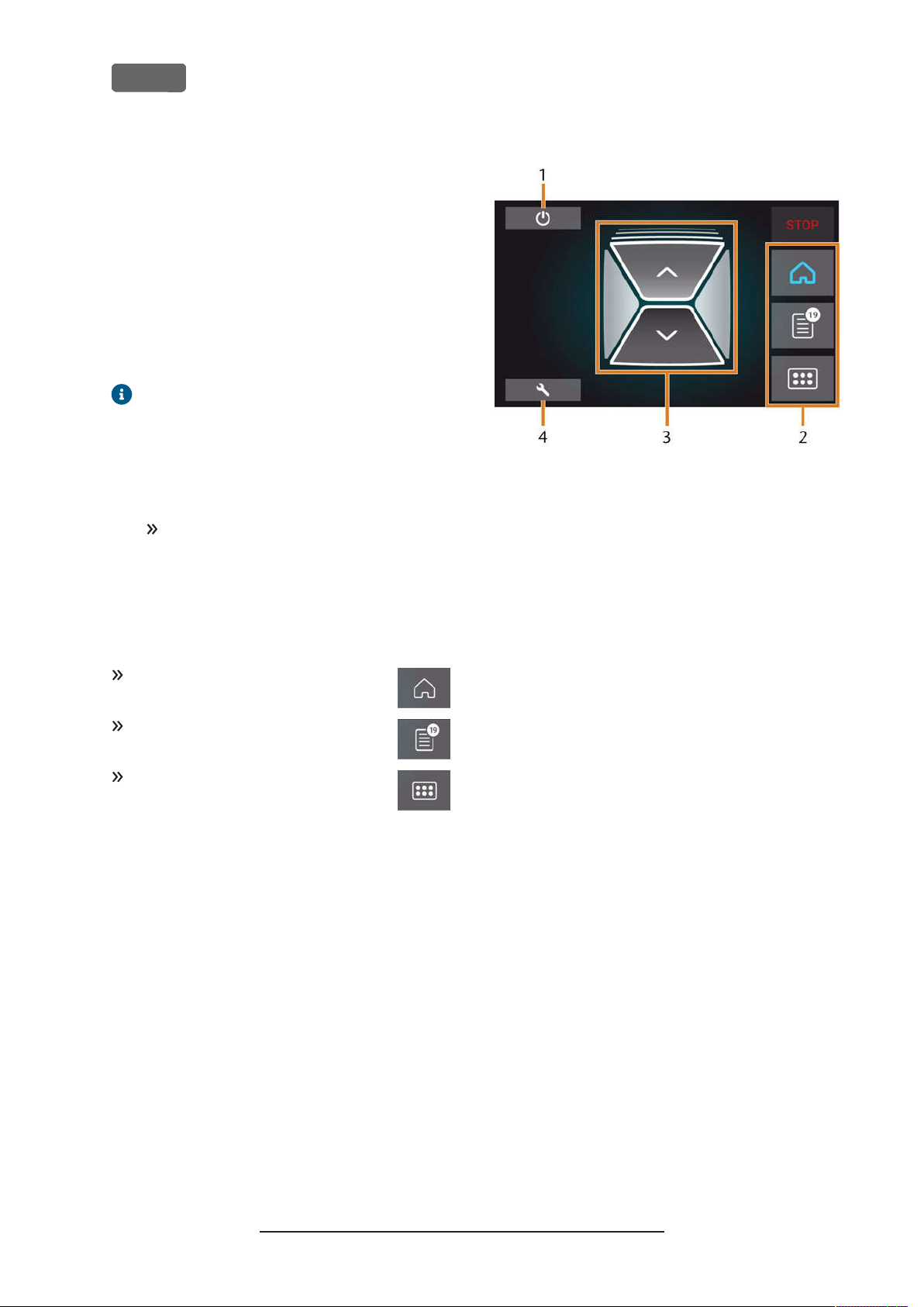
The sections of the touchscreen
The user interface is divided into the 3 main sections
Home,Jobs
at the right display border.
To open the
depicted icon.
and
which you can select via a menu
Tools
section, select the
Home
–
FIG. 32 – H
1.
2.
3.
4.
Mode 2
Z4 – Operation: Preparing jobs
OME S ECTION INMODE
Icon for shutting down the machine
Menu for selecting the individual user interface sections
Icons for operating the working chamber door and
multi-purpose drawer
Icon for opening the
displays during processing:
1
Maintenance
section
To open the
depicted icon.
To open the
depicted icon.
section, select the
Jobs
section, select the
Tools
The Home section of the touchscreen
The
depending on whether the machine is processing or
not.
Mode 1
section has 2 modes which display
Home
displays when the machine is not processing:
Original Operating Instructions:Z4
Version: 12/5/2018
Page 37
Z4 – Operation: Preparing jobs
EN 37
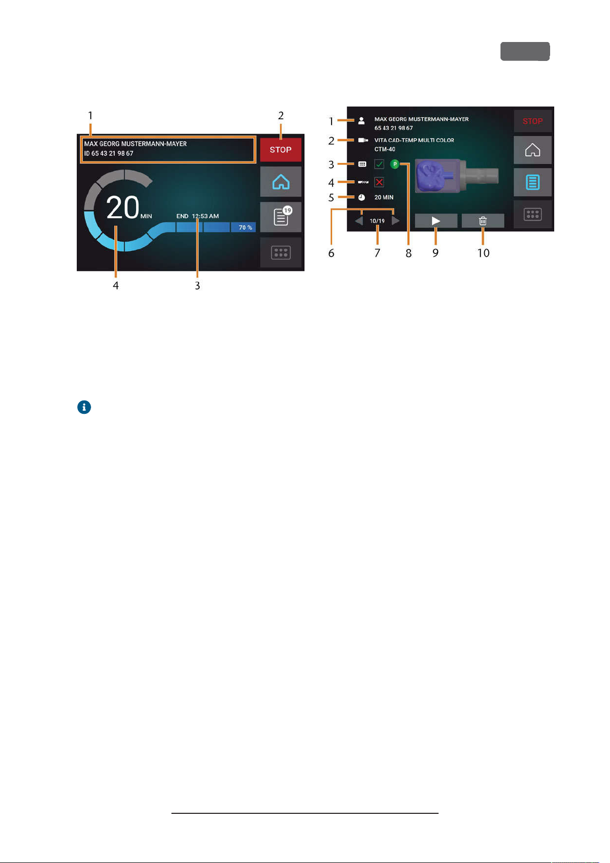
FIG. 33 – H
OME SECTION INMODE
1.
Job details and patient information
2.
Icon for aborting the job
3.
Job end time
4.
Prospective remaining job duration
The remaining job duration is an estimation
based on a self-learning function.
2
The Jobs section of the touchscreen
In the
able jobs. You can use this view to prepare and start
machining. You can delete jobs that you do not need
anymore.
section, you can view details of the avail-
Jobs
FIG. 34 – J
OBS SECTION
1.
Job details and patient information
2.
Required blank type
3.
Check box for the required tool magazine
4.
Check box for the tool life values
5.
Prospective job duration
6.
Arrows to browse through the available jobs
7.
Number of current job/ number of available jobs
8.
Color code of the required tool magazine
9.
Icon for starting the current job
10.
Icon for deleting the current job
Original Operating Instructions:Z4
Version: 12/5/2018
Page 38
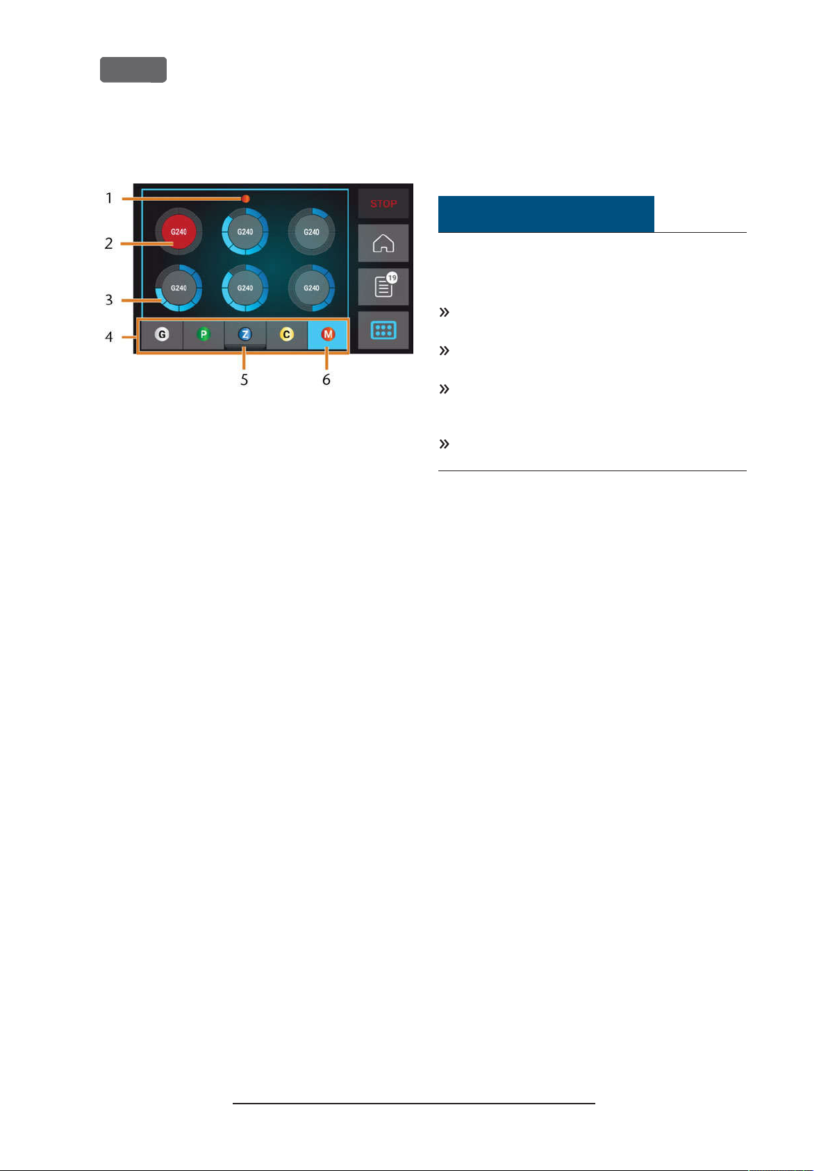
EN 38
Z4 – Operation: Preparing jobs
The Toolssection of the user interface
FIG. 35 – T
OOLS SECTION
1.
Color code of the currently selected tool magazine
2.
Tool with expired tool life (red circle)
3.
Tool life value indicator (blue outer circle)
4.
Menu for selecting the tool magazine
5.
Marking for the tool magazine currently inserted in
the working chamber
6.
Marking for the tool magazine currently shown on
the touchscreen
Exchanging the cooling liquid and
cleaning the tank
NOTICE
Damages caused by wet machining with
unsuitable cooling liquid
Wet machining without suitable cooling liquid can
damage the machine, tools and blanks.
Before you execute a job, ensure that the cooling
liquid is clean and the liquid level is sufficient.
Only use cooling liquid that meets the requirements listed below.
Exchange used cooling liquid according to the
maintenance table. Clean the cooling liquid tank
before refilling it.
If you use a cleaning agent to clean the tank,
ensure that no residues of it remain in the tank.
The machine needs cooling liquid that meets the
following requirements:
Drinking water
n
No added chlorine
n
No distilled water
n
No carbonated water
n
Without sufficient cooling liquid in the tank, wet
machining is not possible. The machine regularly
reminds you via the touchscreen to exchange the
cooling liquid. You can find the appropriate interval in
the maintenance table.Of course, you can exchange
the cooling liquid at any time.
You need to exchange the cooling liquid in the
following cases:
n
The liquid level lies below the
The change interval in the maintenance table has
n
been exceeded.
n
The cooling liquid is soiled.
Every time you exchange the cooling liquid, you must
also clean the tank.
Before every job, you also have to check the strainer
basket and empty it if required.
min
mark.
Emptying the strainer basket
You can empty the strainer basket into a collecting
container as follows:
1.
Lift the cover off the tank.
2.
Remove the strainer basket by pushing it out of
the cover from below.
Original Operating Instructions:Z4
Version: 12/5/2018
Page 39
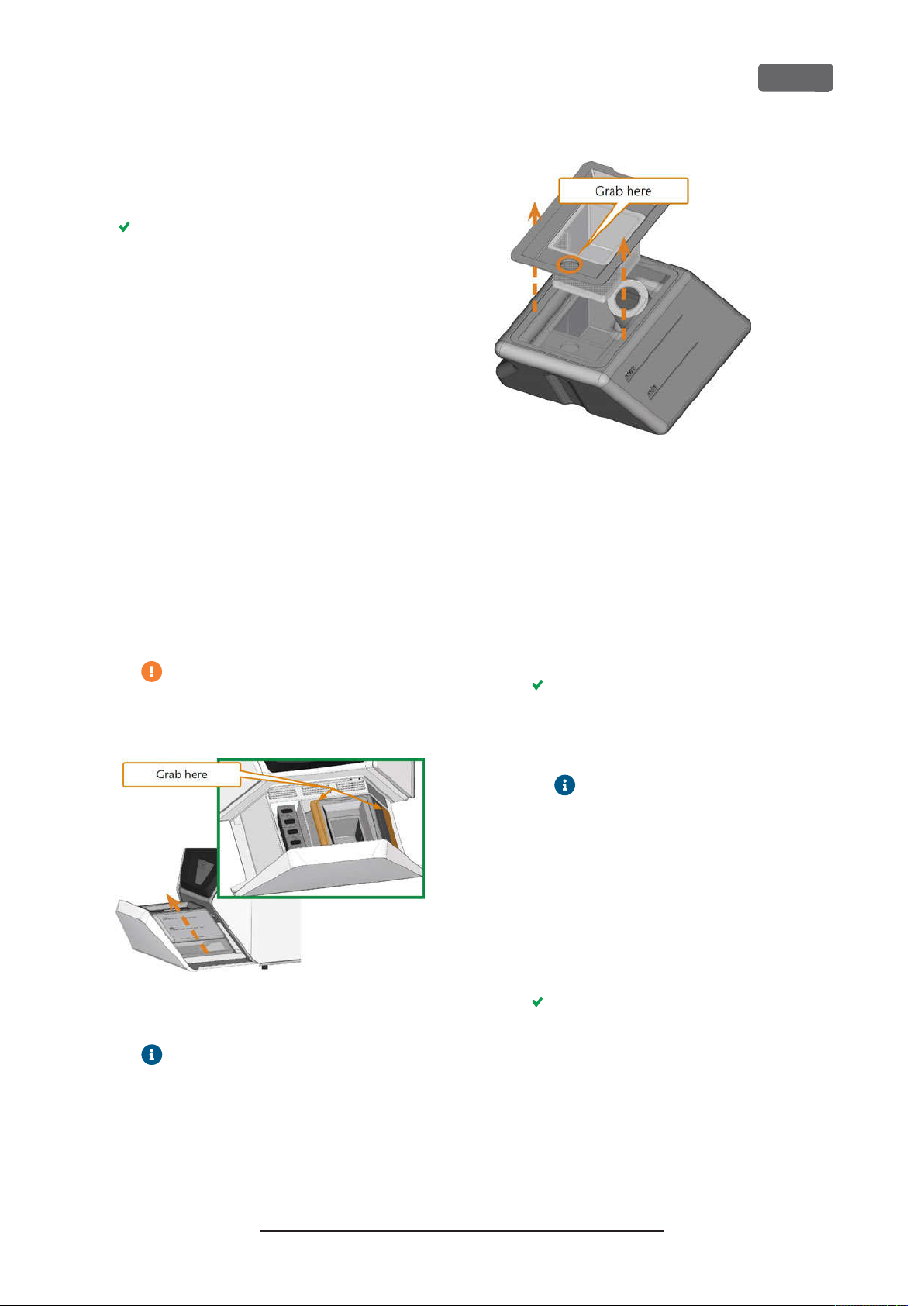
Z4 – Operation: Preparing jobs
3.
Tap out the strainer basket into the collecting container. You can use water or compressed air to further clean the strainer basket.
The strainer basket is completely void of machining residues.
Exchanging or filling in the cooling liquid
You can fill in or exchange the cooling liquid as
follows:
1.
To exchange the liquid and clean the cooling
liquid tank, have the following items readily available:
Collecting container that can hold approx.
n
10 l
Cleaning brush
n
Water for cleaning the cooling liquid tank
n
2.
Ensure that sufficient cooling liquid is available.
3.
Close the working chamber door.
4.
Open the multi-purpose drawer.
5.
Grab the cooling liquid tank at the positions
marked in the following figure. Pull it out of the
drawer in the direction indicated by the arrow (
see below
).
When you tilt the coolingliquid tank, the
cover will not prevent the cooling liquid
from leaking.
EN 39
FIG. 37 – R
7.
Ž
EMOV ING THE COVER FROM THE COOLING L IQUID TANK
If there is cooling liquid in the tank:
a.
Pour the cooling liquid into the collecting
container.
b.
Remove the strainer basket by pushing it
out of the cover from below.
c.
Tap out the strainer basket into the collecting container. You can use water or compressed air to further clean the strainer
basket.
The strainer basket is completely void of
machining residues.
d.
Rinse the filter in the cooling liquid tank
under running water.
FIG. 36 – R
MULTI-PURPOSE DRAWER
EMOV ING THE COOL ING LIQUID TANK FROM THE
Information on the disposal of cooling
liquid and machining residues:
– on page71
6.
Lift the cover off the tank.
Ž
Disposal
If necessary, you can disassemble
the cooling liquid filter to clean it
thoroughly (
carbon filter
e.
Thoroughly clean the tank with the cleaning
Ž
Exchanging the
– on page63
).
brush. Pour the cleaning water into the collecting container.
f.
If you have used a cleaning agent, ensure
that no residues of it remain in the cooling
liquid tank.
The cooling liquid tank is completely void of
liquid, machining and cleaning agent
residues.
8.
Fill the cooling liquid tank with cooling liquid until
it reaches the
9.
Insert the strainer basket into the tank cover and
max
mark.
put the cover onto the tank.
Original Operating Instructions:Z4
Version: 12/5/2018
Page 40
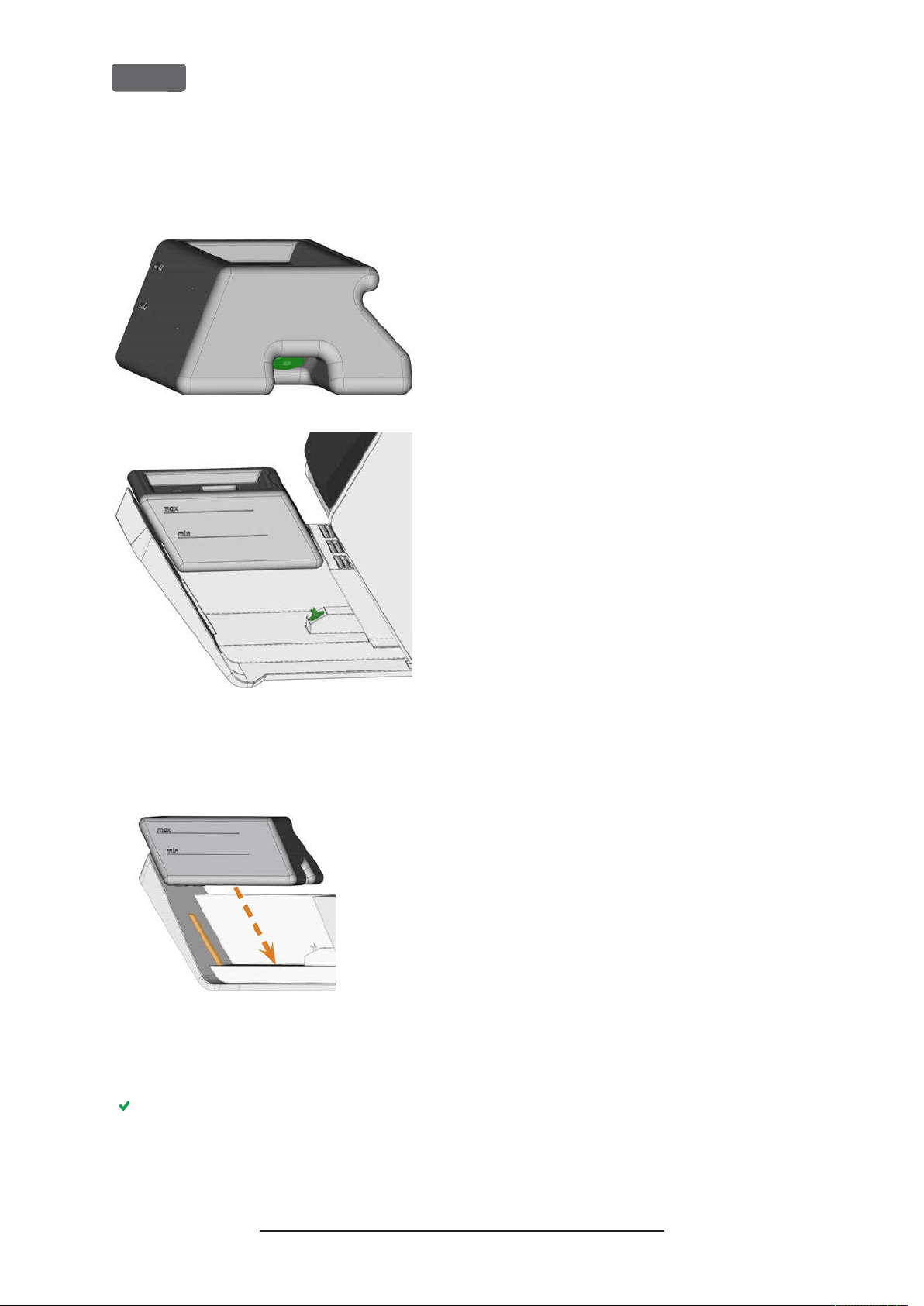
EN 40
10.
Remove dirt and foreign bodies from the coupling of the cooling liquid tank and the counterpart
in the machine.
Z4 – Operation: Preparing jobs
FIG. 38 – T
COLO RED GREE N
(
11.
HE C OUPLIN G OF THE TA NK A ND ITS COUNTERPART
)
Insert the cooling liquid tank with the help of the
guide rail into the multi-purpose drawer.
FIG. 39 – I
DRAWER(GUIDE RA IL COL ORED ORANGE
12.
NSE RTING THE COOLING LIQUID TANK INTO THE
)
Push the tank into its end position until it is properly attached to the machine.
The cooling liquid tank is connected to the cooling liquid system via the coupling.
13.
Close the multi-purpose drawer.
Original Operating Instructions:Z4
Version: 12/5/2018
Page 41
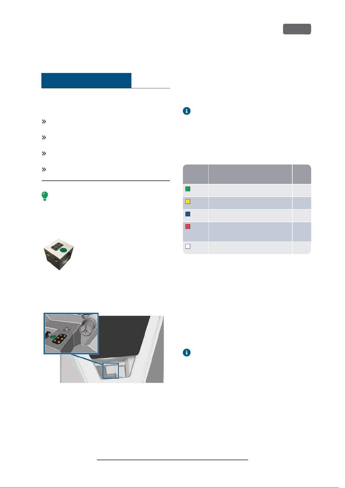
Color
Z4 – Operation: Preparing jobs
EN 41
Managing tools
NOTICE
Damaging of the spindle or the tool
positions if you use improper tools
Improper tools can damage the collet chuck of the
spindle and / or the tool positions.
Only use tools with a sufficiently large chamfer at
the tool shank.
Install a retaining ring as a stop ring according to
DIN 471-A3.
Only insert tools with a maximum diameter of
3mm at the thickest part into the collet chuck.
Only insert tools with a maximum cutting edge diameter of 2.6 mm into the tool magazine.
We recommend original tools as they are
designed especially for the designated jobs.
The machine uses exchangeable tool magazines that
can hold up to 6 tools each.
touchscreen displays the required magazine for each
job and whether it is mounted into the working
chamber.
The machine can change tools automatically during
machining so that it executes jobs without your interference.
If tool magazine inserts are worn, you should
replace them. (
– on page65
inserts
Ž
Replacing the tool magazine
)
Color codes of the tool magazines
The tool magazines have color codes for the individual
materials. In the following table you find an overview:
code
Green Wax and plastics (PMMA) P
Yellow Composites C
Blue Zirconia Z
Red Non-precious metals (Cobalt chrome/
Titanium)
Material Letter
M
FIG. 40 – A
TOOL MAG AZINE
For each job you need to mount the appropriate
magazine into the working chamber.
FIG. 41 – T
HOLD ER;TOOL POS ITIONS MA RKED ORANG E
OOL MAG AZINE WHICH IS MOUNTED TO THE TOOL MA GAZINE
You can store magazines that are currently not needed
in the multi-purpose drawer.
A sensor recognizes the tool magazine which is
currently mounted into the working chamber. The
White Glass ceramics G
Inserting and exchanging tools
You need to insert or exchange tools in the following
cases:
Upon first use of the machine
n
After replacing a tool magazine (in case of loss or
n
damage)
n
After exchanging tool magazine inserts due to
wear
When the tool life of a tool has expired
n
n When tools are damaged or worn
When you select a job in the
check box indicates whether you need to
replace tools before machining.
You can use the
section of the touchscreen for
Tools
managing tools:
n
To check the tool life values.
To check which tool magazine positions the indi-
n
vidual tools are assigned to.
Jobs
section, a
Original Operating Instructions:Z4
Version: 12/5/2018
Page 42
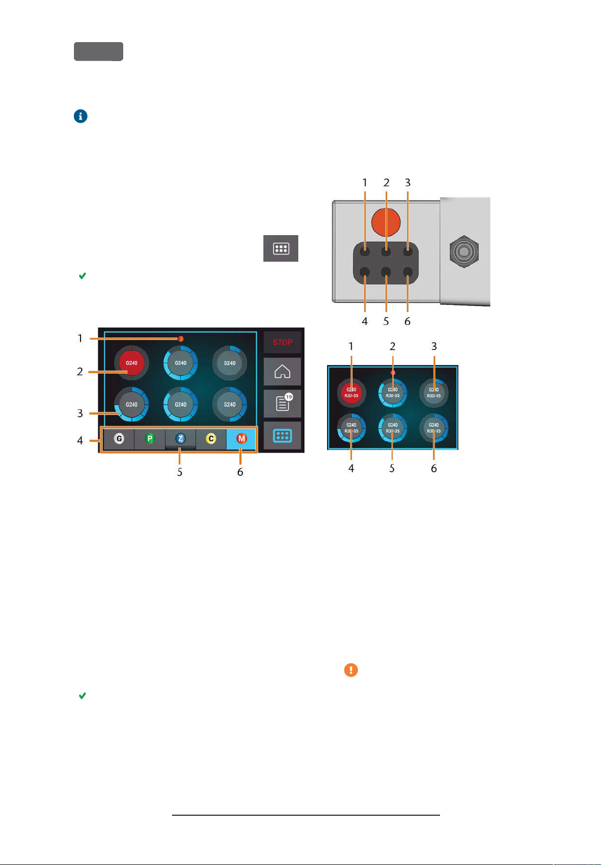
EN 42
The maximum tool life values that you can actually achieve with your tools depend on many
factors, such as the quality of the tools, the
quality of the blanks, how well the machine is
maintained and cleaned etc. Therefore, the
tool life values that your machine is shipped
with are default values. Due to a self-learning
function, they will become more precise over
time.
Z4 – Operation: Preparing jobs
b.
Tools with expired tool life values display in
red.
c.
Each circle is assigned to a specific position of
the corresponding magazine.
To open the
1.
section, select the
Tools
depicted icon.
The
section displays. One of the magazines
Tools
is selected and the corresponding information displays.
FIG. 42 – T
OOLS SECTION
1.
Color code of the currently selected tool
magazine
2.
Tool with expired tool life (red circle)
3.
Tool life value indicator (blue outer circle)
4.
Menu for selecting the tool magazine
5.
Marking for the tool magazine currently inserted
in the working chamber
6.
Marking for the tool magazine currently shown
on the touchscreen
FIG. 43 – TOP: T
OTTOM
B
3.
If tool life values have expired, remove the cor-
OOL POS ITION
OOL POS ITIONS
: T
1 – 6
IN THE TOOL MAGAZINE
1 – 6
ON THE TO UCHSCREEN
responding tools from the tool magazine.
4.
Insert the new tools:
a.
Ensure that the positions of the tools in the
tool magazine match the tool positions on
the touchscreen.
b.
Insert the tools straight into the tool positions with the cutting edge pointing downwards. Push them in until the ring touches
the rubber.
2.
Select the desired tool magazine from the menu
at the bottom display border.
The tools of the corresponding tool magazine display as circles.
a.
In the middle of each circle, the tool match
code displays.
Original Operating Instructions:Z4
If the positions of the tools in the tool
magazine do not match the tool positions
on the touchscreen, the machine will use
the wrong tool(s) during job execution
and the job result will become unusable.
Version: 12/5/2018
Page 43
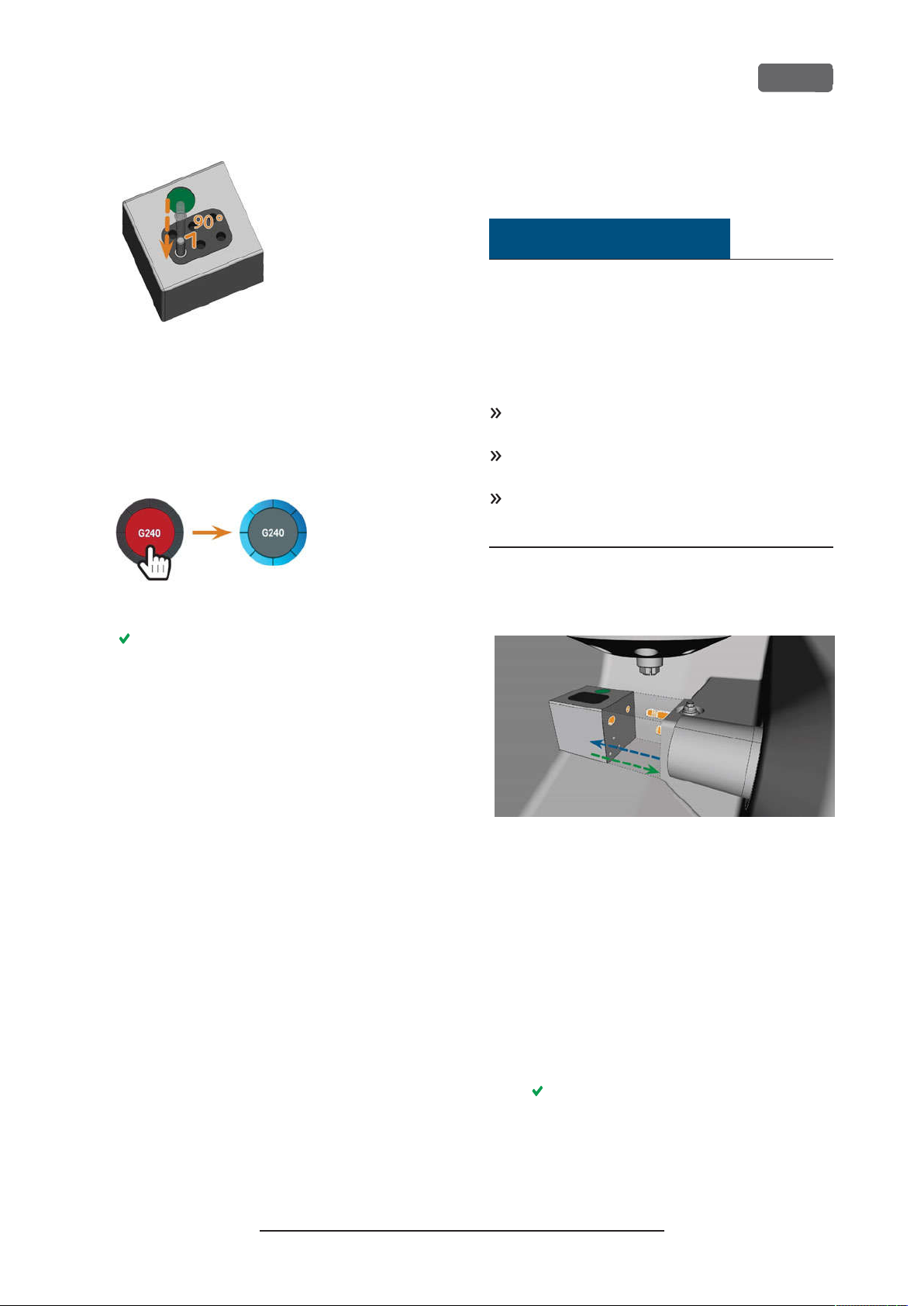
Z4 – Operation: Preparing jobs
FIG. 44 – I
5.
6.
NSE RTING TOOL S INTO THE TOOL POSITIONS
After replacing a tool, reset the tool life value. For
this, select the corresponding element on the
touchscreen.
Plug the tool magazine back onto the tool
magazine holder if required.
EN 43
Mounting exchanging tool
magazines
NOTICE
Damage of the tool magazines and tool
magazine holder
If you tilt tool magazines while mounting them, or if
tool magazines or the tool magazine holder are not
clean, the magazines will not slide smoothly onto the
holder. If you mount or remove tool magazines by
force, you can damage the tool magazine and the tool
magazine holder.
Always keep the tool magazine holder and the
holes in the tool magazines clean.
Grease the tool magazine holder according to the
maintenance table.
Plug tool magazines straightly onto the holder. If
necessary, remove the tool magazine and reposition it.
FIG. 45 – R
ESETTING THE TOOL L IFE VALUES
The tool life value of the tool is reset. The circle
displays in blue.
You exchange tool magazines by pulling them off and
plugging them on the tool magazine holder.
FIG. 46 – E
AND HOLES IN THE TOOL MAGAZINE MARKED ORANG E
In case a tool magazine got stuck on the holder, use
the screw on the backside of the tool magazine:
1.
XCHA NGING THE TOOL MAGAZINE(TOOL MAGAZINE HOLDER
Use the screw as follows:
a.
Pick up a flat blunt tool (e. g. a slot screw
driver)
b.
Use the tool to remove the protective cap
of the screw and put it aside within reach.
c.
Using the provided allen key, turn the
screw to the right.
)
The tool magazine moves backwards and is
released.
Original Operating Instructions:Z4
Version: 12/5/2018
Page 44
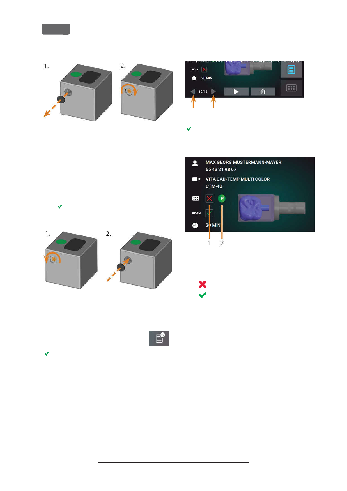
EN 44
Z4 – Operation: Preparing jobs
FIG. 47 – R
SCREW
2.
EMOV ING THE PROTECTIV E CAP(LEFT)AND USING THE
Remove the tool magazine from the working
chamber.
3.
To reset the screw, do the following:
a.
Using the provided allen key, turn the
screw to the left into its original position.
b.
Cover the screw opening with the protective cap.
The screw is reset and the tool magazine is
ready to be mounted again.
FIG. 48 – R
PROTECTIV E CAP
ESETTING THE SCREW(LEFT)AND PLACING THE
You can use the touchscreen to choose the right tool
magazine for the next job:
FIG. 49 – T
HE A RROWS TO SWITCH BETWE EN JOBS
The touchscreen displays the required tool
magazine and if it is mounted into the working
chamber.
FIG. 50 – T
HE TOOL MAG AZINE DE TAIL S I N THEJOBS SECTION
1.
Check box to indicate if the required tool
magazine is mounted:
means
not mounted
means
mounted
2.
The color code and letter of the required tool
magazine (
on page41
Ž
Color codes of the tool magazines
)
–
To open the
1.
section, select the
Jobs
depicted icon.
The
section displays. The details of the next
Jobs
queued job display.
2.
If necessary, switch to the desired job by using
the left and right arrow in the left bottom corner
of the touchscreen.
Original Operating Instructions:Z4
3.
4.
Version: 12/5/2018
If an incorrect tool magazine is mounted, remove
this magazine by pulling it off the tool magazine
holder (
Ž
Fig. 46 –
on the previous page
, blue
arrow).
To mount the required tool magazine, identify it
by comparing the color code:
Page 45
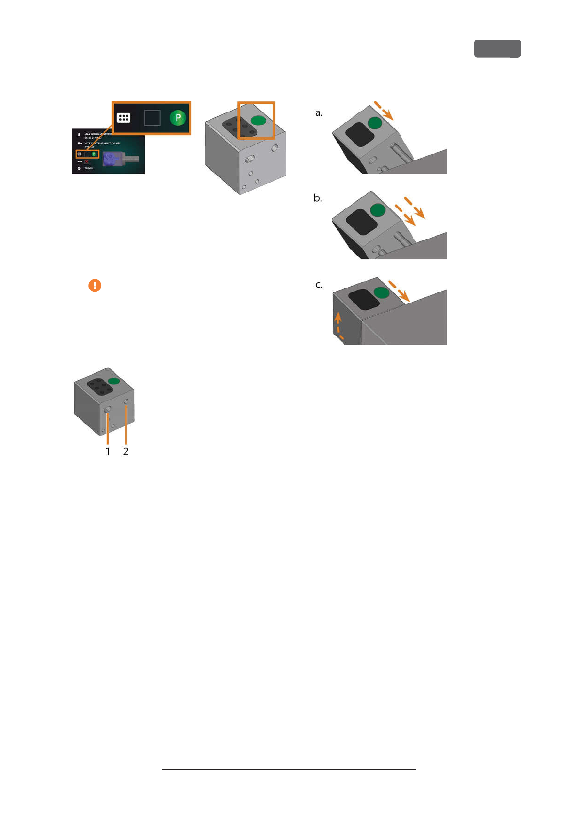
Z4 – Operation: Preparing jobs
EN 45
FIG. 51 – T
THE TOOL MAG AZINE ARE IDENTICAL
5.
HE C OLOR CODE ON THE TOUCHSC REEN(LEFT)AND ON
Ensure that the contact surfaces of the tool
magazine holder and the tool magazine are
clean.
You can only execute jobs when the
machine recognizes the required tool
magazine.
6.
Plug the tool magazine onto the tool magazine
holder (
FIG. 52 – THE2
1.
Larger front hole
2.
Smaller rear hole
Ž
Fig. 46 –
HOLES IN A TOOL MAGA ZINE
on page43
, green arrow):
FIG. 53 – P
MAG AZINE HOLD ER IN3STEPS
LUGGING A TOOL MAGA ZINE ONTO THE TOOL
a.
Position the larger rear hole on the longer
bolt of the tool magazine holder. Push it
onto the bolt until you feel a resistance.
b.
Overcome the resistance by pushing the
tool magazine harder onto the bolt.
c.
Align the smaller front hole with the shorter
bolt of the tool magazine holder. Push the
tool magazine onto the short bolt until it is
properly seated on the tool magazine
holder.
Original Operating Instructions:Z4
Version: 12/5/2018
Page 46
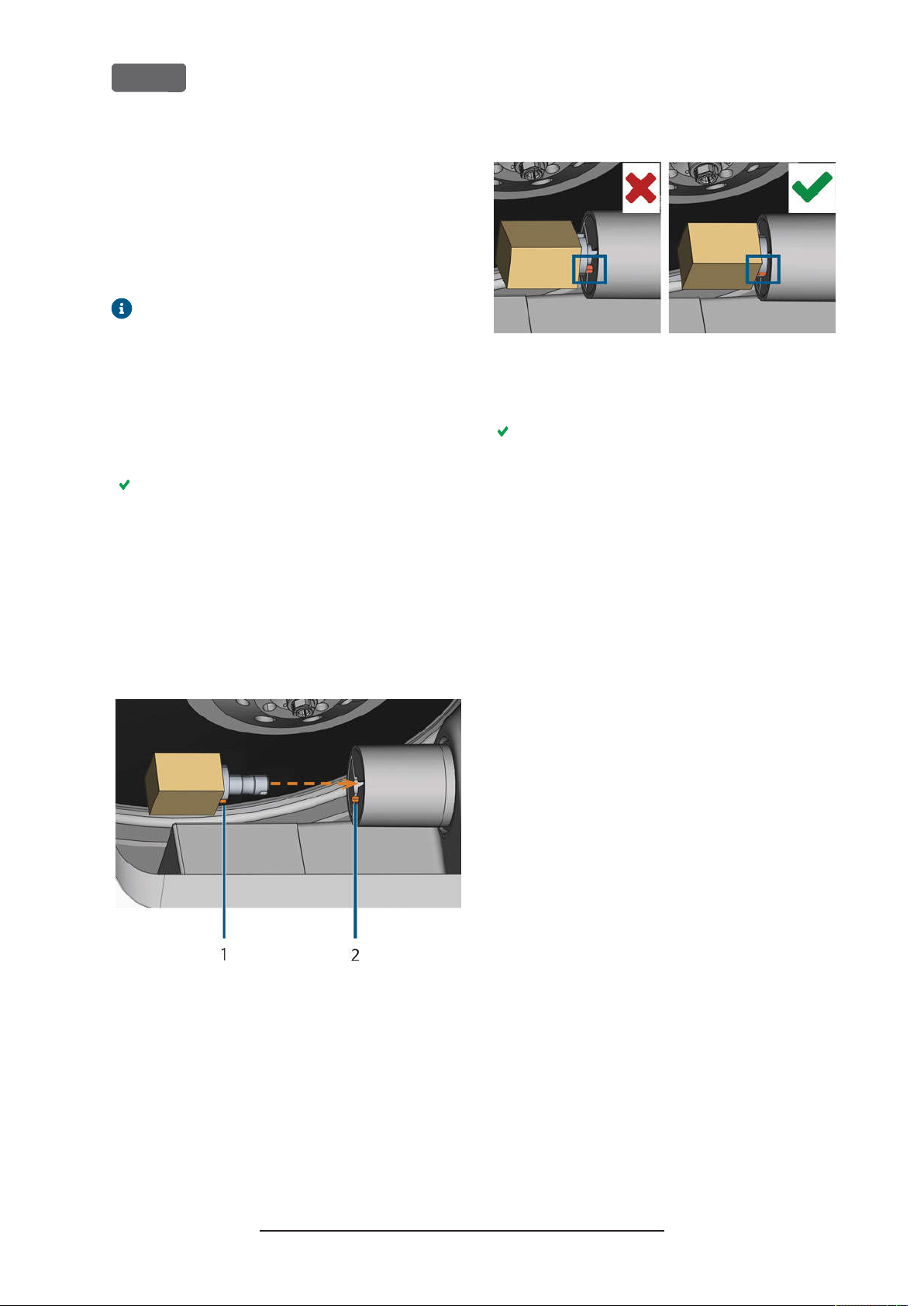
EN 46
Mounting removing blanks
The machine can process the following blanks:
n
Blocks, max. size: 40x 20x 20mm (L/D/H)
Prefabricated abutments
n
*
requires extra equipment
You can obtain extra equipment from
customer service.
Mounting removing blocks
You can mount blocks to the block holder where a
collet chuck immobilizes them. The collet chuck
opens and closes with the working chamber door.
1.
Open the working chamber door.
The working chamber door is open. The collet
chuck is open.
2.
Pull the block out of the holder if any.
3.
Check the collet chuck for dirt.
If necessary, clean the collet chuck (
4.
the collet chuck of the blank holder
5.
Place the required block in the collet chuck of the
block holder: Align the groove of the block [1]
with the positioning pin of the block holder [2].
*
Ž
Cleaning
– on page60
Z4 – Operation: Preparing jobs
FIG. 55 – (A) B
SURFA CE OF BLOCK HAS FUL L CONTACT
7.
Close the working chamber door.
LOCK HAS ONLY PARTIA L CONTA CT
The working chamber door is closed. The collet
chuck is closed. The block is mounted.
).
; (B) B
ASE
FIG. 54 – I
GROOV E AND POSITIONI NG PIN MARKED ORANGE
(
6.
NSE RTING THE BLOCK INTO THE BLOCK HOLDER
1.
Groove of the block
2.
Positioning pin of the block
)
Push the block into the block holder until it clicks
in. If the block does not click in, twist it until the
positioning pin lies in the groove.
Original Operating Instructions:Z4
Version: 12/5/2018
Page 47
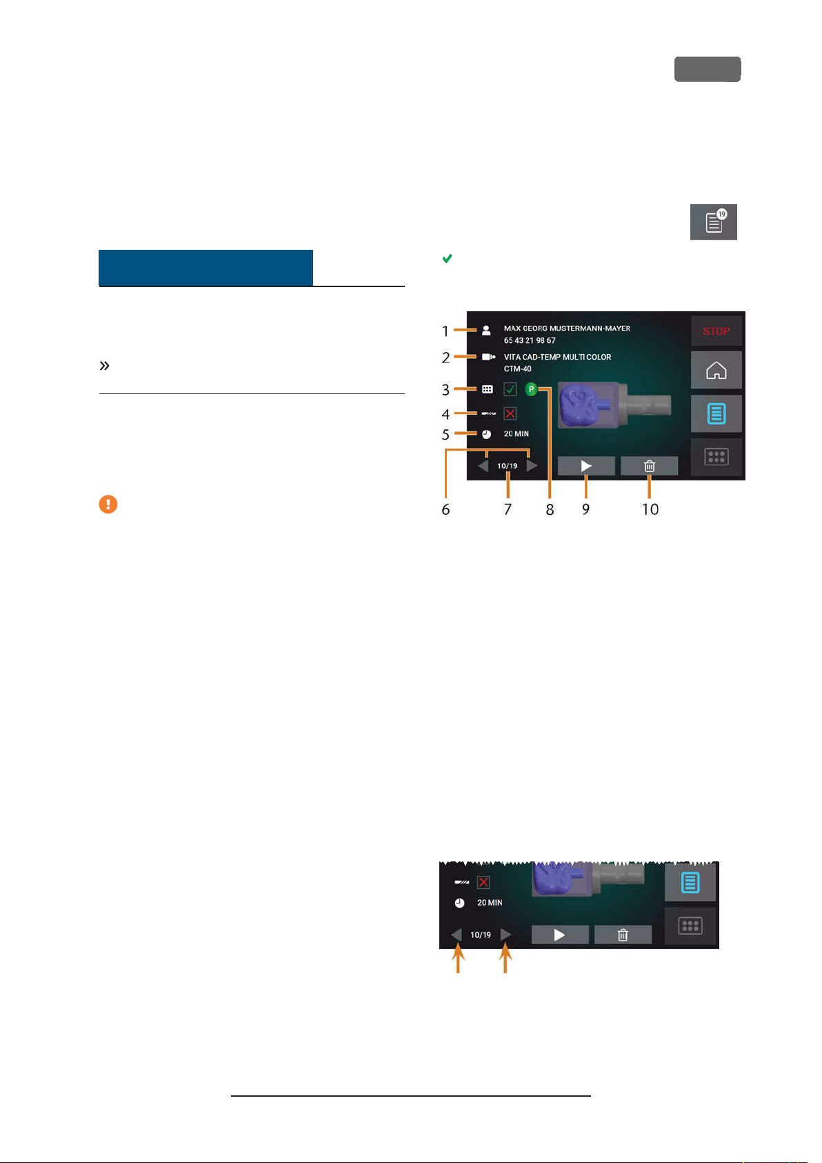
Z4 – Operation: Executing jobs
EN 47
7 Operation: Executing
jobs
Overview
NOTICE
Damaging of the machine when using
damaged tools or blanks
If tools or blanks are damaged, parts can break off and
damage the machine during job execution.
Check the blanks and tools
age before every job execution.
When you have prepared your jobs and your machine,
you can start machining. Machining is a fully automated process and only requires your attention in case
of unexpected events.
Do not move the machine during job execution, otherwise the results may become imprecise.
thoroughly
for dam-
Starting jobs via the touchscreen
Following you find the workflow for selecting,
checking and executing jobs.
To open the
1.
depicted icon.
The
queued job display.
FIG. 56 – J
section displays. The details of the next
Jobs
OBS SECTION
section, select the
Jobs
1.
Ensure the following:
You created a job on your CAD computer. It
n
has been transferred to the machine.
The correct tool magazine is inserted into
n
the working chamber.
All required tools are in the right positions in
n
the tool magazine and are neither worn nor
damaged.
The required blank is mounted.
n
There is enough cooling liquid in the cool-
n
ing liquid tank.
2.
Close the working chamber door.
3.
Start machining via the touchscreen.
1.
Job details and patient information
2.
Required blank type
3.
Check box for the required tool magazine
4.
Check box for the tool life values
5.
Prospective job duration
6.
Arrows to browse through the available jobs
7.
Number of current job/ number of available jobs
8.
Color code of the required tool magazine
9.
Icon for starting the current job
10.
Icon for deleting the current job
2.
Use the arrows in the left bottom corner to select
the desired job.
FIG. 57 – T
HE A RROWS TO SWITCH BETWE EN JOBS
Original Operating Instructions:Z4
Version: 12/5/2018
Page 48

EN 48
3.
Verify that the elements [2], [3], [4] display as
required:
a.
Ensure that the mounted blank corresponds
to [2] (if not:
– on page46
b.
If displays in [3], mount the correct tool
magazine (
magazines
c.
If displays in [4], replace all worn tools
(
Ž
Managing tools
4.
To start machining, select the depicted icon.
The following happens:
a.
If required, the working chamber door
closes.
b.
The machine starts processing.
c.
The working chamber is illuminated in blue.
d.
The remaining machining duration displays
on the touchscreen.
Ž
Mounting removing blanks
).
Ž
Mounting exchanging tool
– on page43
).
– on page41
Z4 – Operation: Executing jobs
).
FIG. 58 – H
OME SECTION INMODE
1.
Job details and patient information
2.
Icon for aborting the job
3.
Job end time
4.
Prospective remaining job duration
2
If you are prompted that a firmware
update exists:
the machine
Ž
Updating the firmware of
– on page68
The remaining job duration is an estimation based on a self-learning function.
5.
If using exocad ChairsideCAD, do not shut down
your CAD computer or disconnect it from the network until machining has finished. Otherwise,
you may have to restart your machine and the
job.
6.
Wait until the machine has finished.
The working chamber door opens. The following
dialog displays on the touchscreen.
FIG. 59 – T
HE D IAL OG AFTER A JOB HAS BEEN FINISHED
7.
Remove the blank from the working chamber
and check whether the job has been executed
correctly.
8.
If you are satisfied, select the depicted
icon on the touchscreen.
Original Operating Instructions:Z4
Version: 12/5/2018
Page 49

Z4 – Operation: Executing jobs
EN 49
The job is marked as finished and no longer displays in the
You can restore finished jobs with
DentalCNC. Read the corresponding documentation for more details.
9.
If you need to repeat the job, select
the depicted icon on the touchscreen.
The job continues to display in the
You can restart it as required.
10.
Leave the working chamber door open so that
the working chamber can dry.
After machining, air is blown into the working
chamber for some time to help dry the
working chamber, which causes air noise. This
does not indicate that there is a malfunction.
Jobs
section.
Jobs
section.
Aborting machining
You can cancel machining at any time. You need to
restart the job with a new blank. You cannot continue
the job with the used blank because the machine will
not recognize this blank and you will receive an error
message.
1.
To cancel machining, select the depicted icon.
The machine prompts you to confirm the cancellation.
2.
To confirm your choice, select the
depicted icon.
The spindle puts the tool which is currently in the
collet chuck into the tool magazine. The working
chamber door opens.
3.
If the working chamber is wet, leave the working
chamber door open so that the working chamber
can dry.
Job interruptions and job abortions
A job will be interrupted in the following cases:
The compressed air supply is not sufficient
n
The cooling liquid flow rate is not sufficient
n
An interrupted job will normally be continued automatically after the error is corrected.
A job will be aborted in the following cases:
In case of a machine malfunction
n
In case of a tool breakage
n
n
In case of a power failure
If a job was aborted, you have to restart it.
You need to restart the job with a new blank.
You cannot continue the job with the used
blank because the machine will not recognize
this blank and you will receive an error
message.
Original Operating Instructions:Z4
Version: 12/5/2018
Page 50

EN 50
How to proceed in case of a job interruption
If the job was interrupted, the touchscreen displays a
corresponding message.
If the compressed air is insufficient
1.
Wait a couple of seconds. This may already solve
the problem.
2.
Restart the machine.
3.
If the problem persists, contact customer service.
If the cooling liquid flow rate is insufficient
1.
Check if there is enough cooling liquid in the
tank.
2.
Check if the cooling liquid and the tank including
the filter are clean.
How to proceed in case of a machine malfunction
A machine malfunction is recognized by the internal
control unit in case of a critical event. The working
chamber will be illuminated in red. The touchscreen
displays the error message and error code that was
sent by the control unit.
1.
Record the error message and error code that is
displayed.
2.
Restart the machine and the CAM computer. If
the problem persists, continue with the next
step.
3.
Disconnect the machine from the electrical
source and prevent it from being restarted.
4.
Contact customer service. Have the error message and error code readily available.
5.
If you need to remove a blank from the working
chamber, perform an emergency opening of the
working chamber door.
How to proceed in case of a tool breakage
If a tool breaks during machining, the machine will not
recognize this immediately. Instead, the spindle will
continue to move with the broken tool. The tool
breakage will be recognized upon the following
events:
The next regular tool change
n
The next check for broken tools, if activated in
n
the application settings of DentalCNC.
Z4 – Operation: Executing jobs
The tool was damaged or worn
n
The tool was put into the wrong tool magazine
n
position or was manually inserted into the
spindle at the wrong time. As a consequence, it
was not suitable for the processing step.
The distribution of the objects in the blank
n
(“nesting”) was not correct.
If a tool breaks, do the following:
1.
Open the working chamber door.
2.
Remove all parts of the broken tool from the working chamber and the collet chuck.
3.
If the spindle picked up the tool from the tool
magazine, check if the tool was inserted into the
correct position. Insert a spare tool into the correct position in the tool magazine.
4.
If you manually inserted the tool into the collet
chuck, check if the broken tool corresponds to
the tool type which you were prompted to insert.
Have a correct spare tool ready.
5.
Close the working chamber door.Restart the job.
You need to restart the job with a new blank.
You cannot continue the job with the used
blank because the machine will not recognize
this blank and you will receive an error
message.
If tools break regularly, you can find additional
information in the troubleshooting section:
Troubleshooting
– on page72
Ž
How to proceed in case of a power failure
As long as the machine is not powered, you do not
have access to the working chamber. You also have no
access to the drawer.
After a short power failure, restart the machine
and the CAM computer.
If you need to access the working chamber in case
of a longer power failure, perform an emergency
opening of the working chamber door.
If you need to access to the multi-purpose drawer,
perform an emergency opening of the drawer.
A tool breakage can be caused by the following:
Original Operating Instructions:Z4
Version: 12/5/2018
Page 51
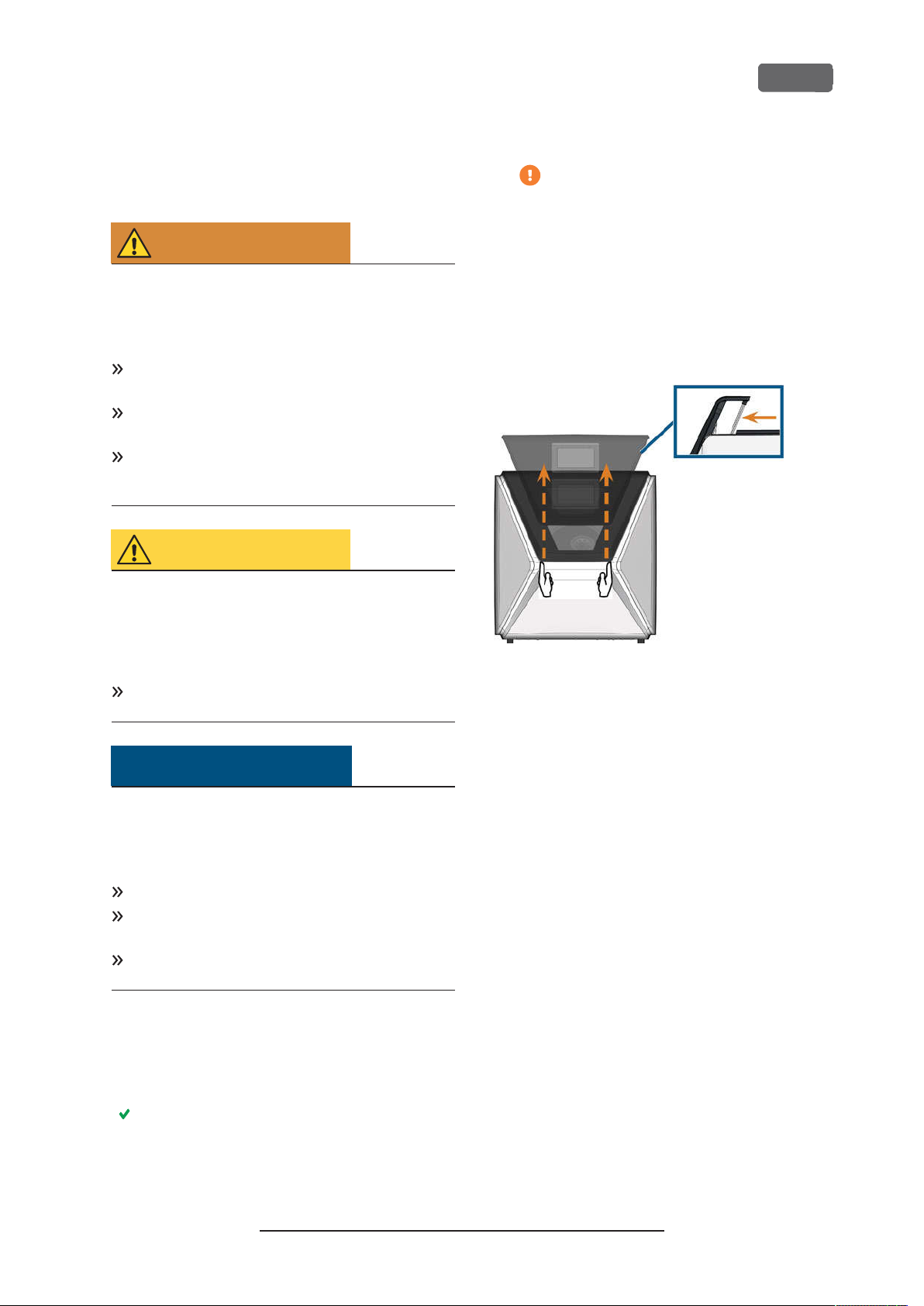
Z4 – Operation: Executing jobs
EN 51
Emergency opening of the working chamber door
WARNING
Crushing hazard and cutting injuries if the
working chamber door is open
If the working chamber door is open during
machining, it will not protect users from bruises and
cuts.
Do not
during machining.
Never
chamber door open.
Perform the emergency opening only if you are
authorized to do so and if you have received training on it.
open or close the working chamber door
operate the machine with the working
CAUTION
Cutting injuries when touching a rotating
tool
If a power failure or a machine malfunction occurs
duringmachining, the spindle including the inserted
tool keeps rotating. If you touch the rotating tool, you
will suffer from cuttinginjuries.
Wait until the spindle has stopped rotating before
performing an emergency opening.
NOTICE
Improper opening or closing of the working
chamber door
To avoid damage, heed the following instructions
when you manually open or close the working
chamber door.
Disconnect the machine from the eletrical source.
Prevent the working chamber door from twisting
by pushing or pulling it with
Only apply as much force as needed to overcome
the resistance.
both
hands.
The working chamber door should move
sluggishly, but evenly. If the movement is
jerky or the working chamber door gets
stuck, do not use excessive force.
2.
Open the working chamber door by straightly
and evenly pushing it upwards with both hands.
3.
If the working chamber door can only be moved
with very high effort, ensure that the guide rails at
the back are clean.
FIG. 60 – E
AND CHECKING THE GUID E RA ILS
4.
5.
MERGE NCY OPEN ING OF THE WORKING CHAMBER D OOR
If the working chamber is wet, leave the working
chamber door open so that the working chamber
can dry.
Close the working chamber door by carefully
pushing it downwards with both hands.
You can perform an emergency opening as follows:
1.
Switch off the machine at the main power
switch.Disconnect the machine from the eletrical
source.
You can manually open the working chamber
door.
Original Operating Instructions:Z4
Version: 12/5/2018
Page 52
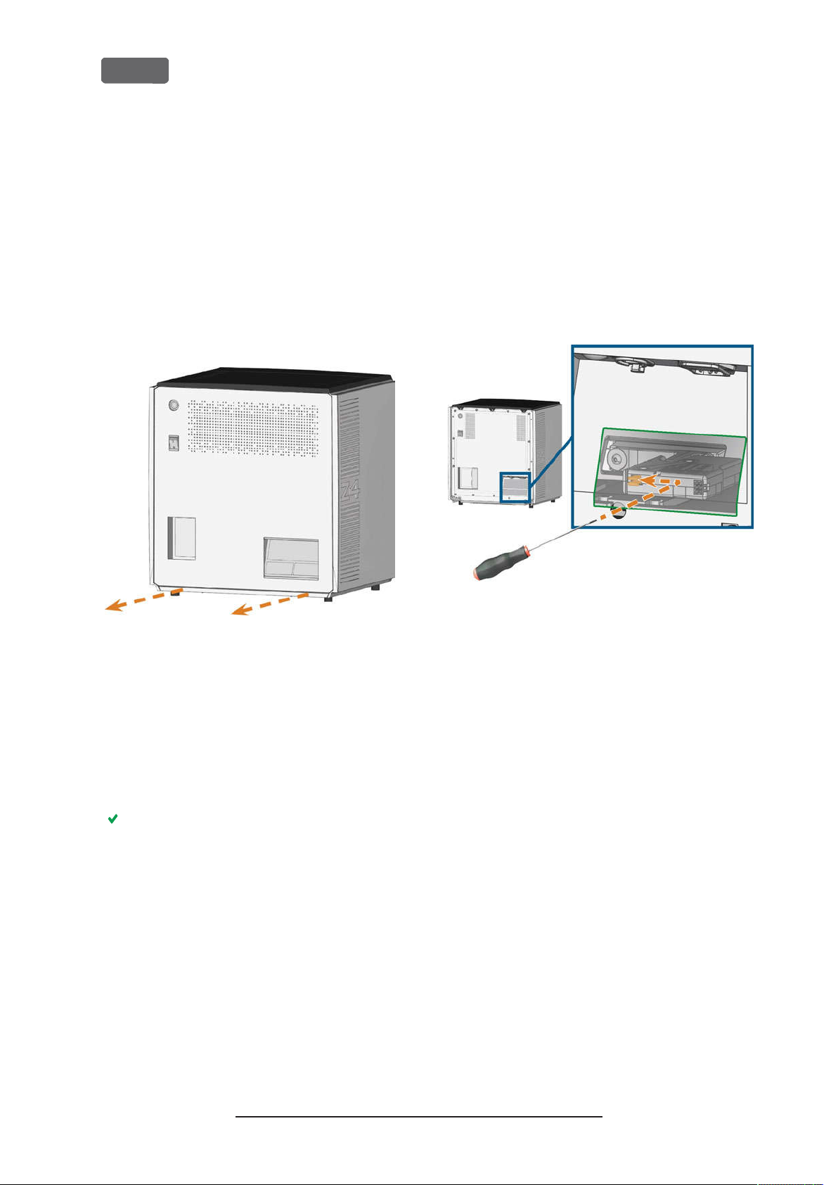
EN 52
Z4 – Operation: Executing jobs
Removing the back panel cover
You need to remove the back panel cover of the
machine for an emergency release of the multipurpose drawer.
You can remove the back panel cover as follows:
1.
Switch off the machine at the main power switch.
2.
Disconnect the machine from all lines.
3.
Grab the bottom edge of the back panel cover
and pull it towards you as indicated by the
arrows:
Emergency opening of the multipurpose drawer
In case of a longer power failure, you can manually
open the multi-purpose drawer as follows:
Remove the back panel cover (
1.
back panel cover
2.
Insert a screwdriver with 5cm minimum length
into the depicted opening at the backside of the
machine.
– see above
Ž
).
Removing the
FIG. 61 – R
4.
EMOV ING THE BACK PANEL COVE R
To re-install the back panel cover, do the following:
a.
Align the top edge of the machine and the
cover so that the start button and main
power switch lie in the center of the respective openings.
b.
Push the cover against the machine housing.
The cover is held in place by magnets.
FIG. 62 – E
3.
4.
5.
MERGE NCY RELEASE OF THE MULTI-PURPOSE DRAWER
Push the screw driver in the upper right direction
until you encounter a resistance.
Use the screwdriver to push the lever for the
emergency release to the left until the mechanism is unlocked.
Install the back panel cover.
Original Operating Instructions:Z4
Version: 12/5/2018
Page 53

Z4 – Maintenance and do-it-yourself
EN 53
8 Maintenance and do-
it-yourself
Some day-to-day basic maintenance and preventive
maintenance is essential to keep the machine mechanics and electric components in good condition for
proper machining results.
It is your responsibility to make sure that preventive
maintenance, as well as basic maintenance, is
performed.
You are the only one who can ensure that your
machine receives the proper maintenance care. You
are a vital link in the maintenance chain.
Basic maintenance
Basic maintenance includes tasks which are part of
everyday operation. You are responsible to ensure
that these tasks are carried out according to the maintenance table. You only need minimal manual skills for
these tasks and most required tools are provided with
the machine.
Maintenance section
For your convenience, the machine lists all basic maintenance tasks in the
screen. In the
the individual tasks are due.
When you have marked a maintenance task as
complete, its time interval is reset and the list is
updated accordingly.
Maintenance
Maintenance
section on the touch-
section, you can see when
Where to get service?
Customer service is your main contact for all service
related questions. They will provide you with spare
parts, maintenance tips and they will perform
preventive maintenance for you on request.
When your machine is delivered or installed, ask
the service technician for contact details for the
customer service team. We also recommend
scheduling the first preventive maintenance
appointment at this point to ensure your machine
gets proper maintenance.
Definition of wear parts
The machine and the extra equipment are warranted
for a period of 24 months or 2,000 operating hours,
whatever comes first. The warranty covers defects in
materials or fabrication as long as the regulations for
using the machine in all documents are followed.
Of course, the warranty also covers wear parts as long
as their failure cannot be attributed to the functionrelated abrasion. The wear parts that are mentioned in
the maintenance table can already wear down within
the warranty period due to their normal function. The
average useful life of the wear parts can be seen in the
maintenance table.
Use these values to determine operating costs, to plan
your spare part stock as well as to create individual
maintenance and service plans.
Maintenance table
page 69
Ž
Preventive maintenance
Preventive maintenance for this machine has to be
scheduled every 2years, or after 1,000operating
hours at the latest.
To schedule preventive maintenance, contact customer service.
Original Operating Instructions:Z4
Version: 12/5/2018
Page 54
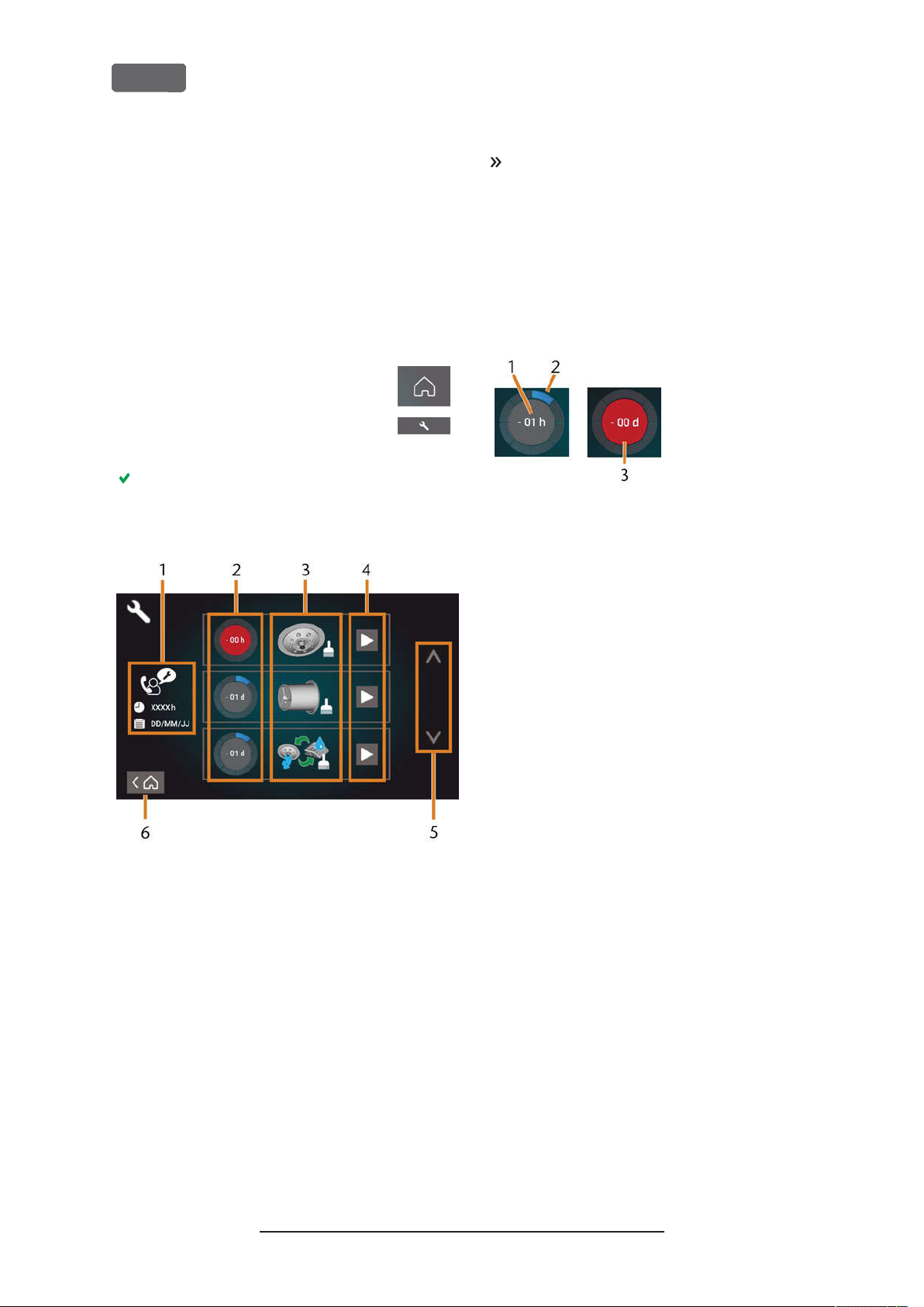
EN 54
Using the maintenance section
For your convenience, the machine lists all basic maintenance tasks in the
screen. In the
the individual tasks are due.
When you have marked a maintenance task as
complete, its time interval is reset and the list is
updated accordingly.
You can open the maintenance section as follows:
Maintenance
Maintenance
section on the touch-
section, you can see when
Z4 – Maintenance and do-it-yourself
Use the circles in the first column to determine
how much time remains until the task is due:
The numbers in the circles show how many oper-
n
ating hours (h) or days (d) are left before the
task must be performed.
The number of blue segments decreases over
n
time.
If a circle is red, the corresponding task is due.
n
To open the
1.
depicted icon.
To open the
2.
select the depicted icon.
The
Maintenance
screen lists all required maintenance tasks in
order of their urgency.
section, select the
Home
Maintenance
section displays. The touch-
section,
FIG. 64 – C
IRCLES INDICATING WHEN A TASK IS DUE
1.
The remaining time (here: 1 operating hour)
2.
Only 1 segment remains because the task is due soon
3.
The red circle indicates that this task is due
FIG. 63 – T
TASKS
In the center of the screen the list with all maintenance tasks displays. The higher a task is listed, the
more urgent it is.
HE MA INTENANCE S ECTION WITH THE LIS T OF MAINTENANCE
1.
Preventive maintenance: remaining operating hours/
due date
2.
Circles showing the urgency of the task
3.
Illustrations depicting the individual tasks
4.
Start icons to begin the individual tasks
5.
Arrows to scroll through the list
Icon to go back to the
6.
Home
section
Original Operating Instructions:Z4
Version: 12/5/2018
Page 55
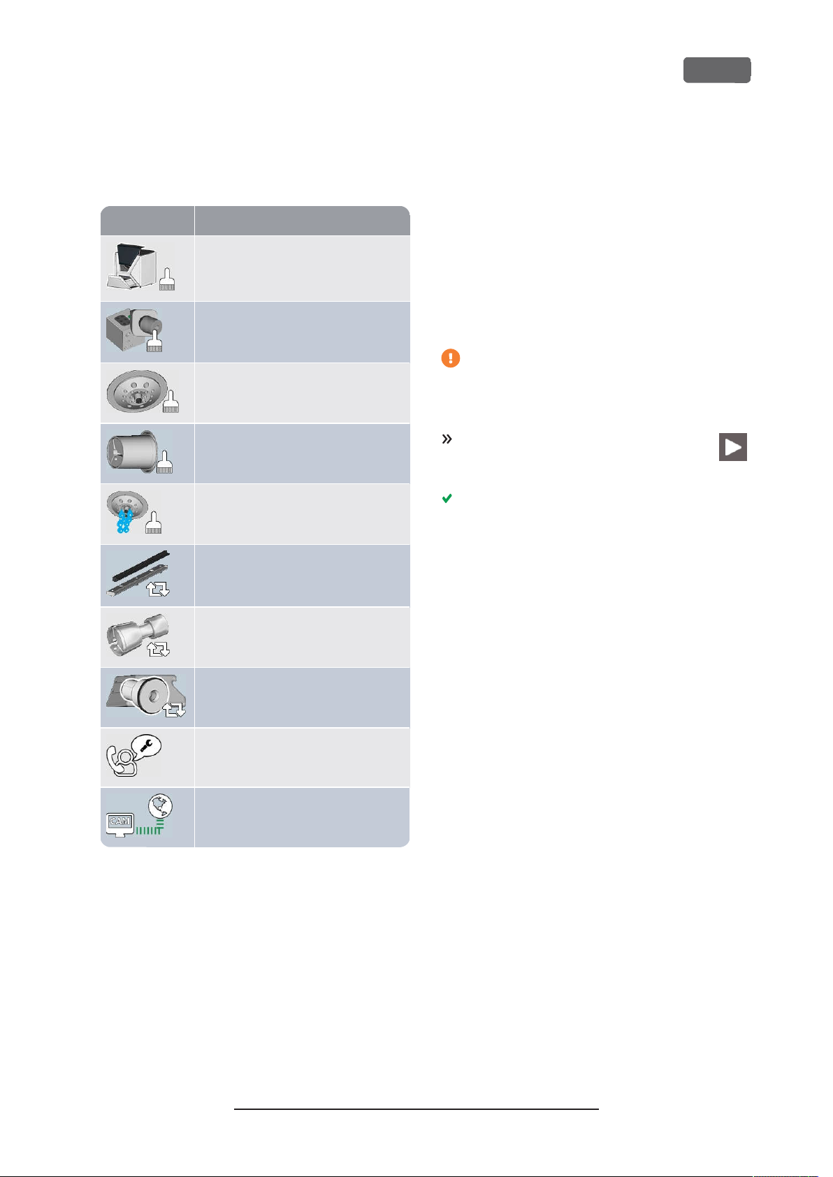
Illustration Task
Z4 – Maintenance and do-it-yourself
EN 55
List of all maintenance tasks
The following maintenance tasks and illustrations can
display on the touchscreen:
Daily cleaning
(working chamber, cooling liquid tank)
Weekly cleaning
(webcam, tool magazines and holder)
Cleaning the spindle collet chuck
Cleaning the blank holder collet chuck
Rinsing the cooling liquid system
(rinsing, exchanging the carbon filter)
Exchanging the view window wiper
Performing maintenance tasks
The
Maintenance
screen guides for every maintenance task. To perform
the maintenance tasks you need to use the respective
guide. With the guides you can do the following:
Read the basic steps required to perform indi-
n
vidual maintenance tasks.
Execute necessary machine functions for indi-
n
vidual tasks.
Mark individual tasks as complete.
n
The on-screen guides do not replace the
detailed information in this manual. Here you
can find additional instructions and safety
information.
To start a maintenance task, select the
depicted icon for the respective entry in
the
Maintenance
The corresponding on-screen guide opens. It has
several pages which will guide you through the
maintenance task.
section contains interactive on-
section.
Exchanging the blank holder collet chuck
Exchanging the cooling liquid coupling
Preventive maintenance
Internet connection (Backup / Update)
1
Only customer service can complete this task and
1
2
reset the time interval.
2
This task only appears if the machine is not regularly
connected to the internet. The task is completed automatically as soon as a connection is established.
Original Operating Instructions:Z4
Version: 12/5/2018
Page 56
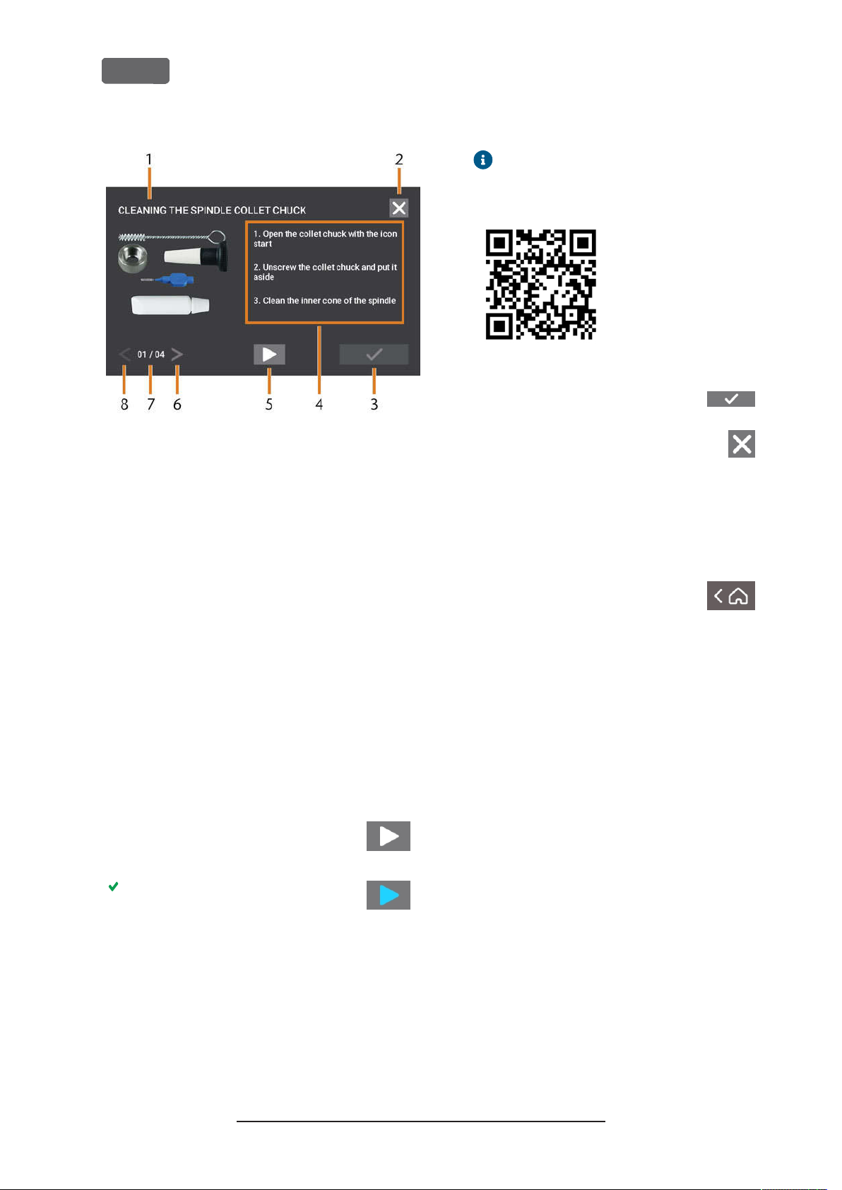
EN 56
Z4 – Maintenance and do-it-yourself
The internet version may contain newer
information than this document.
FIG. 65 – I
You can use the on-screen guides as follows:
1.
2.
3.
4.
NTERACTIVE ON-SCREEN G UIDE FOR MAINTENA NCE TASK
1.
Title of the on-screen guide
2.
Icon to close the guide without marking the task as
complete
3.
Icon to mark the task as complete
4.
Numbered instructions
5.
Icon for a required machine operation (e. g. open collet chuck – only for some tasks)
6.
Go to next page
7.
Current and maximum page of the guide
8.
Go to previous page
Select the arrows [6/8] to navigate through the
guide.
Follow the instructions [4] on every page of the
guide.
Perform the maintenance task as required.
If the depicted icon displays, select it
to execute the required machine function for the maintenance task.
FIG. 66 – QR
6.
To mark the task as complete, select
the depicted icon.
7.
To close the guide without marking the
task as complete, select the depicted
icon.
CODE
Leaving the Maintenance section
To close the
1.
2.
Maintenance
Ensure that the list with maintenance tasks displays.
To go back to the
select the depicted icon.
section, do as follows:
section,
Home
The icon changes its color as depicted
and the the machine function is
executed.
5.
If you want to open the internet version of the
detailed maintenance instructions, use the QR
code. Alternatively, visit the following website
and search forZ4and
dentalportal.info
maintenance
:
Original Operating Instructions:Z4
Version: 12/5/2018
Page 57
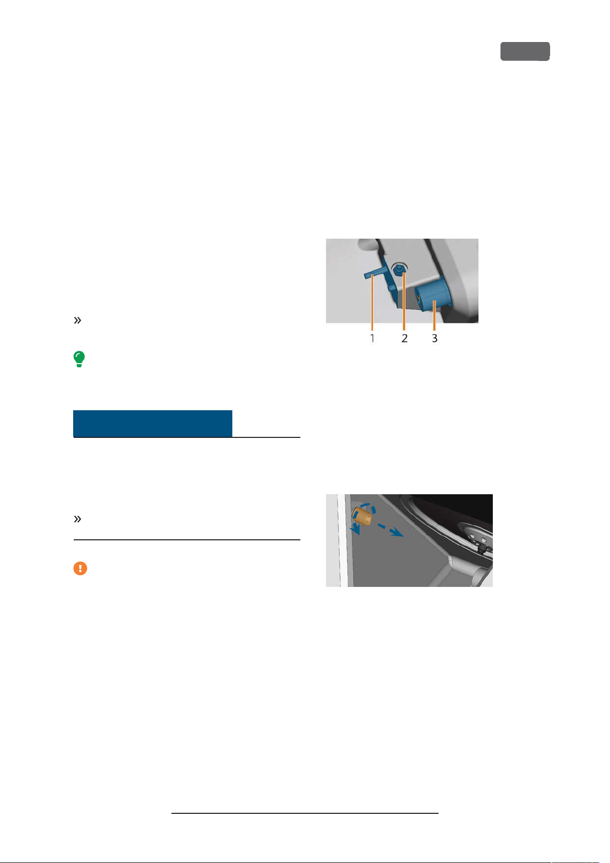
Z4 – Maintenance and do-it-yourself
EN 57
Cleaning the working chamber
Cleaning the working chamber includes the following
components:
Measuring key
n
Blank holder
n
View window
n
Webcam
n
Tool magazines
n
Tool magazine holder
n
These components have different maintenance intervals according to the maintenance table. Therefore,
you should perform a daily and a weekly cleaning of
the working chamber and clean the components
which need cleaning.
When performing the weekly cleaning, also perform the daily cleaning.
We recommend cleaning the working
chamber after all other required maintenance
tasks.
NOTICE
Performing the weekly cleaning
1.
Have ready: The cleaning brush for the blank
holder.
2.
Remove the tool magazine from the working
chamber. Clean it with the cloth and the brush.
3.
Open the multi-purpose drawer. Clean the other
tool magazines.
4.
Clean the blank holder with its respective brush.
FIG. 67 – T
HOLD ER(IN BLUE
OOL MAG AZINE HOL DER
1.
Tool magazine holder
2.
Measuring key
3.
Blank holder
)
EAS URING KEY
, M
, B
LOCK
Damaging of the linear guides or the
spindle when cleaning with compressed air
or ultrasound
If you clean the working chamber with compressed air
or ultrasound, material chips can reach the linear
guides or the spindle bearings.
Never
pressed air or ultrasound.
1.
2.
3.
4.
clean the working chamber with com-
Do not pouradditional water into the working
chamber. The cooling liquid tank may overflow.
Have ready:
n
A wet cloth
A mild cleaning agent(optional)
n
Cleaning brush for the blank holder
n
n
A wet brush for the measuring key
Open the working chamber door.
Clean all surfaces and cracks in the working chamber thoroughly with a wet cloth. Use a mild cleaning agent if necessary.
Clean the measuring key with the wet brush.
5.
Screw the protective cap off the webcam and
clean the inside of the cap with a dry cloth.
FIG. 68 – S
6.
CREWIN G THE PROTECTIVE CAP OFF THE WEBCAM
Clean the webcam with a wet cloth. Screw on the
protective cap.
7.
Clean the tool magazine holder thoroughly.
8.
Apply a bit of collet grease to the bolts of the tool
magazine holder.
9.
To apply the collet grease to the holes of all tool
magazines, mount all tool magazines once.
Original Operating Instructions:Z4
Version: 12/5/2018
Page 58
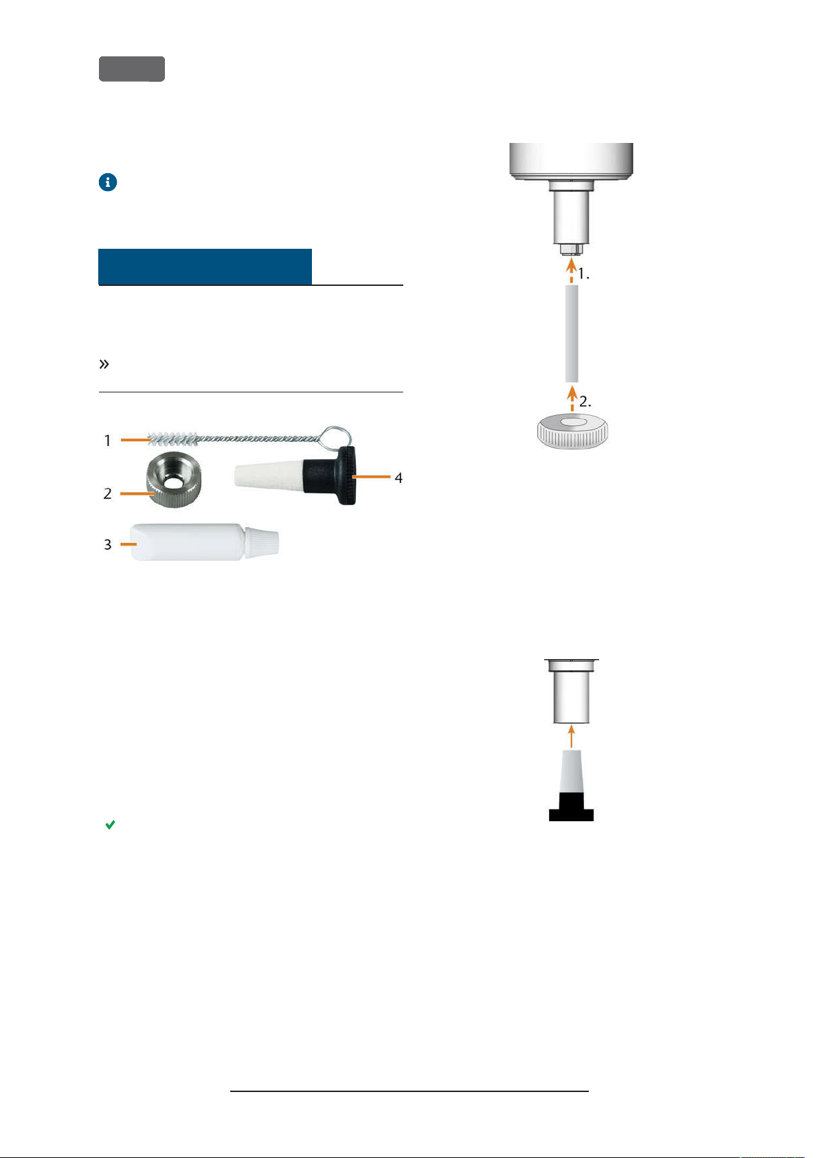
EN 58
Cleaning the collet chuck
The grease for the collet chuck of the spindle
and for the collet chuck of the blank holder is
the same item.
NOTICE
Damaging of the spindle when cleaning
with compressed air or ultrasound
If you clean the collet chuck with compressed air or
ultrasound, the spindle bearings can be damaged.
Clean the collet chuck
service set.
with the appropriate
only
Z4 – Maintenance and do-it-yourself
FIG. 69 – S
To clean the collet chuck do the following:
1.
2.
3.
4.
PINDLE SERVICE SE T
1.
Cleaning brush
2.
Knurled nut
3.
Tube of collet chuck grease
4.
Cleaning cone
Have the spindle service set ready.
Start the maintenance by selecting the corresponding entry in the
the touchscreen.
The following happens:
a.
The on-screen quick guide displays.
b.
The working chamber door opens.
Open the collet chuck using the quick guide.
Put the knurled nut to the spindle with one hand.
With the other hand insert the measuring pin into
the collet chuck and keep holding it.
Maintenance
section on
FIG. 70 – U
5.
6.
7.
FIG. 71 – C
8.
NSCREWING THE COL LET CHUCK
Loosen the collet chuck with the knurled nut.
Unscrew the collet chuck with your hand or with
the knurled nut.
Remove the measuring pin from the collet chuck.
Then put it aside within reach together with the
knurled nut.
Clean the inner cone of the spindle with the
cleaning cone of the service set.
LEANING THE INNER CONE OF THE SPINDLE
Clean the collet chuck with the brush of the service set.
Original Operating Instructions:Z4
Version: 12/5/2018
Page 59
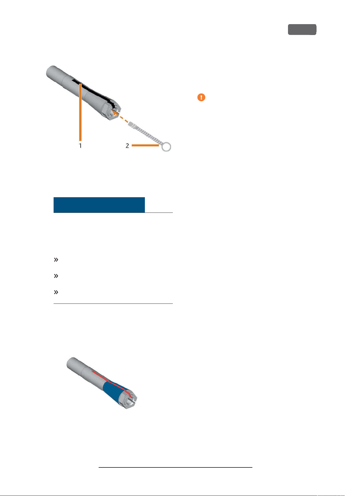
Z4 – Maintenance and do-it-yourself
FIG. 72 – C
LE ANIN G THE COLLE T CHUCK
1.
Longitudinal slot
2.
Cleaning brush
11.
Insert the measuring pin into the collet chuck
with one hand and keep holding it. Screw the collet chuck with the knurled nut in your other hand
tightly into the spindle.
Turn the knurled nut as far as you can so
that the collet chuck is properly seated in
the spindle. Otherwise rotational imperfections can occur during operation which
will worsen your processing results
12.
Remove the measuring pin from the collet chuck
and store it together with the other components
of the spindle service set.
13.
Clean the nozzle plate.
EN 59
NOTICE
Damaging of the spindle when using
the wrong grease or applying the
grease incorrectly
If you use unsuitable grease or if grease gets into
the longitudinal slots of the collet chuck, the
machine may get damaged.
Ensure that no grease gets into the longitudinal slots of the collet chuck.
Only use a very small, about pinhead-size
amount of the grease.
Only use the provided grease of the service
set.
9.
Put a small amount of the collet grease on the
index finger and smear it with the thumb.
10.
Apply the smeared collet grease to the flanks of
the collet chuck.
FIG. 73 – G
GREA SE IS TO BE A PPLIED IS MARKED IN BLUE;SL OT THA T MAY NOT
BE GREAS ED IS MARKED IN RED
REAS ING THE COLLET CHUCK;SURFA CE IN WHICH
Original Operating Instructions:Z4
Version: 12/5/2018
Page 60
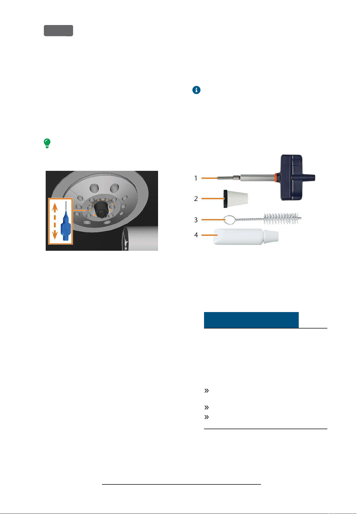
EN 60
Z4 – Maintenance and do-it-yourself
Cleaning the nozzle plate
You should clean the nozzle plate every time you
clean the collet chuck.
1.
Have the interdental brush ready.
2.
Open the working chamber door.
3.
Clean the ring of 8 holes in the inner area of the
nozzle plate. For this, move the interdental brush
up and down.
If necessary, apply some water with a cleaning
agent and let it sit for some minutes.
Cleaning the collet chuck of the
blank holder
The grease for the collet chuck of the spindle
and for the collet chuck of the blank holder is
the same item.
1.
Have ready:
Blank holder service set
n
Collet chuck grease
n
FIG. 74 – C
LEANING THE NOZZLE PL ATE;NOZZLE S MARKED ORANGE
FIG. 75 – B
LA NK HOL DER SERV ICE SE T
1.
Torque screwdriver (1.8Nm)
2.
Cleaning cone
3.
Cleaning brush
4.
Tube of collet chuck grease
NOTICE
Damaging of the block holder when
using the wrong torque screwdriver or
performing the maintenance with the
machine switched off
If you use a torque screwdriver other than the one
included in the scope of delivery, or if you
perform the maintenance with the machine
switched off, the block holder can get damaged.
Ensure that the machine is switched on during
the entire duration of the repair.
Only use the provided torque screwdriver.
Ensure that you apply a maximum torque of
1.8Nm.
2.
Switch on the machine at the main power switch.
3.
Open the working chamber door.
Original Operating Instructions:Z4
Version: 12/5/2018
Page 61
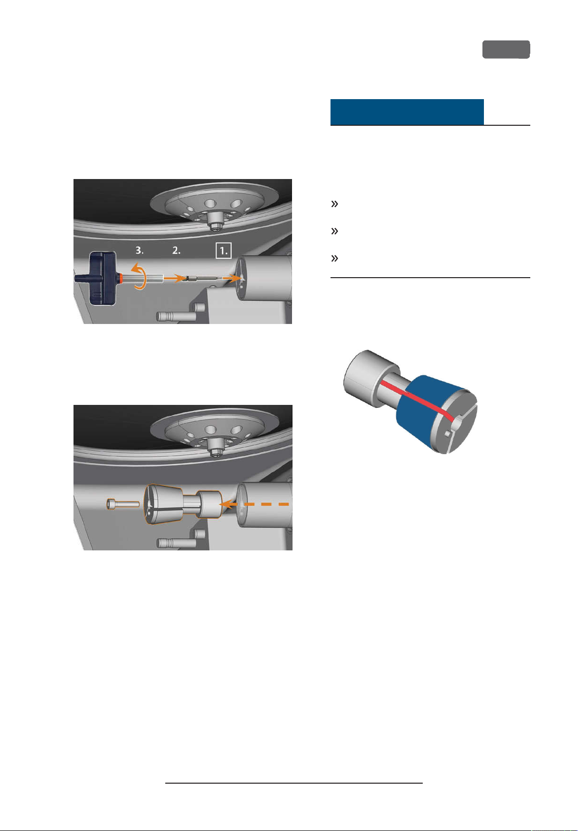
Z4 – Maintenance and do-it-yourself
4.
Insert the bit of the torque screwdriver into the
collet chuck and hold it in place.
5.
Put the torque screwdriver on the bit and
unscrew the screw by twisting the torque screwdriver.
FIG. 76 – L
CHUCK
OOSENING THE SCREW OF THE BLANK HOLDER COL LET
NOTICE
Damaging of the collet chuck when
using the wrong grease or applying the
grease incorrectly
If you use unsuitable grease or if grease gets into
the longitudinal slots of the collet chuck, the
machine may get damaged.
Ensure that no grease gets into the longitudinal slots of the collet chuck.
Only use a very small, about pinhead-size
amount of the grease.
Only use the provided grease of the service
set.
9.
Clean the outside of the collet chuck.
10.
Grease the collet chuck. Apply the grease only to
the conical surface of the collet chuck.
EN 61
6.
Remove the collet chuck and the screw from the
blank holder. Put both items aside within reach.
FIG. 77 – R
7.
EMOV ING THE COLLET CHUCK F ROM THE BLA NK HOLDER
Clean the inner cone of the blank holder with the
cleaning cone of the service set.
8.
Clean the collet chuck with the brush of the service set.
FIG. 78 – G
GREA SE IS TO BE A PPLIED IS MARKED IN BLUE;SL OT THAT MAY NO T
BE G REAS ED IS MARKED IN RED
11.
REAS ING THE COLLET CHUCK;SURFA CE IN WHICH
Check the condition of the fixing screw and
replace it by a spare screw if necessary.
12.
Push the collet chuck with fixing screw into the
blank holder as far as you can. Twist the collet
chuck until it snaps in place and is properly
seated. Depending on the position you may
need to twist it up to 360°.
Original Operating Instructions:Z4
Version: 12/5/2018
Page 62
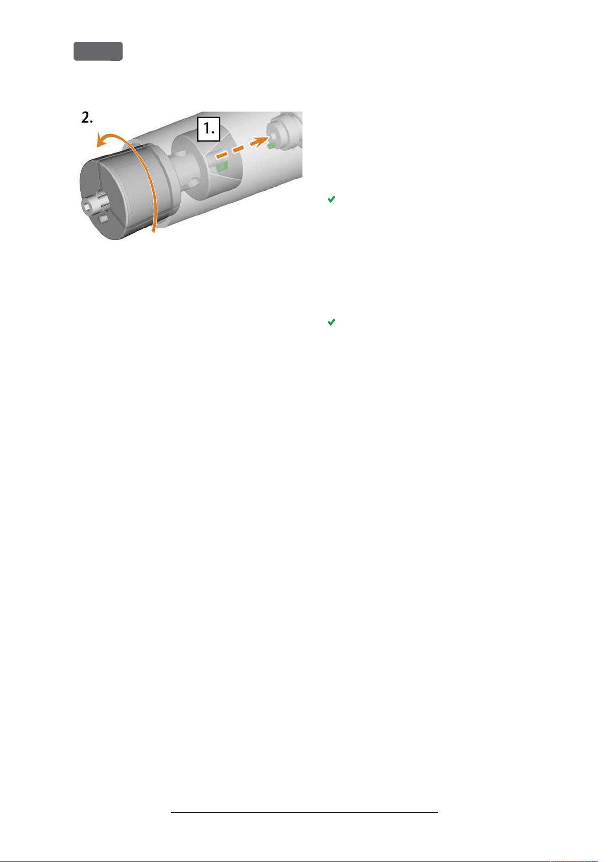
EN 62
FIG. 79 – I
13.
14.
NSE RTING THE COLLET CHUCK INTO THE BLA NK HOLDER
Insert the bit of the torque screwdriver into the
collet chuck and hold it in place.
Put the torque screwdriver on the bit and screw
down the screw by twisting the torque screwdriver.
Z4 – Maintenance and do-it-yourself
Rinsing the cooling liquid circuit
To remove foreign bodies from the cooling liquid
system of your machine, you need to rinse the system.
1.
Start the rinsing program by selecting the corresponding entry in the
the touchscreen.
The following happens:
a.
The on-screen guide displays.
b.
The multi-purpose drawer opens.
2.
Empty and clean the cooling liquid tank.
3.
Refill the tank.
4.
Close the multi-purpose drawer.
5.
To startrinsing, confirm the dialog.
The rinsing program runs automatically.
6.
Wait until the rinsing program has ended.
7.
Exchange the carbon filter.
Maintenance
section on
Original Operating Instructions:Z4
Version: 12/5/2018
Page 63
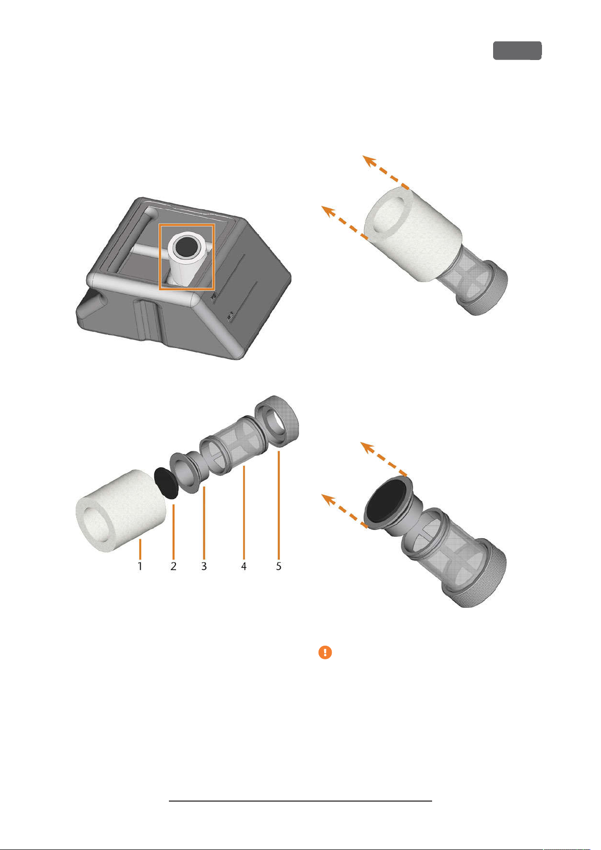
Z4 – Maintenance and do-it-yourself
Exchanging the carbon filter
The cooling liquid tank of your machine is equipped
with a cooling liquid filter that consists of different
filter components, including the carbon filter. The
carbon filter contains activated carbon pellets that you
need to exchange regularly.
2.
Remove the fine filter by stretching the top end a
bit and straightly pulling it off the filter with both
hands.
EN 63
FIG. 80 – C
FIG. 81 – T
1.
Fine filter
2.
Carbon filter cap
3.
Carbon filter
4.
Mesh filter
5.
Filter socket
OOLING LIQUID F ILTER IN THE TANK
HE C OMPONENTS OF THE COOLING LIQUID F ILTER
FIG. 82 – R
3.
EMOV ING THE FINE F ILTER
Clean the fine filter under running water. If the
fine filter is too soiled for proper cleaning,
replace it with a new one when reassembling the
filter.
4.
Remove the carbon filter by straightly pulling it
off the filter.
FIG. 83 – R
EMOV ING THE CARBON FIL TER
If you tilt the filter or move it abruptly in the
next step, you may spill the activated carbon
pellets.
To exchange the activated carbon pellets in the filter,
do the following:
1.
Empty and clean the cooling liquid tank.
Original Operating Instructions:Z4
Version: 12/5/2018
5.
Carefully lift the carbon filter cap with your fingernail or a flat blunt tool and pull it off the carbon filter.
Page 64
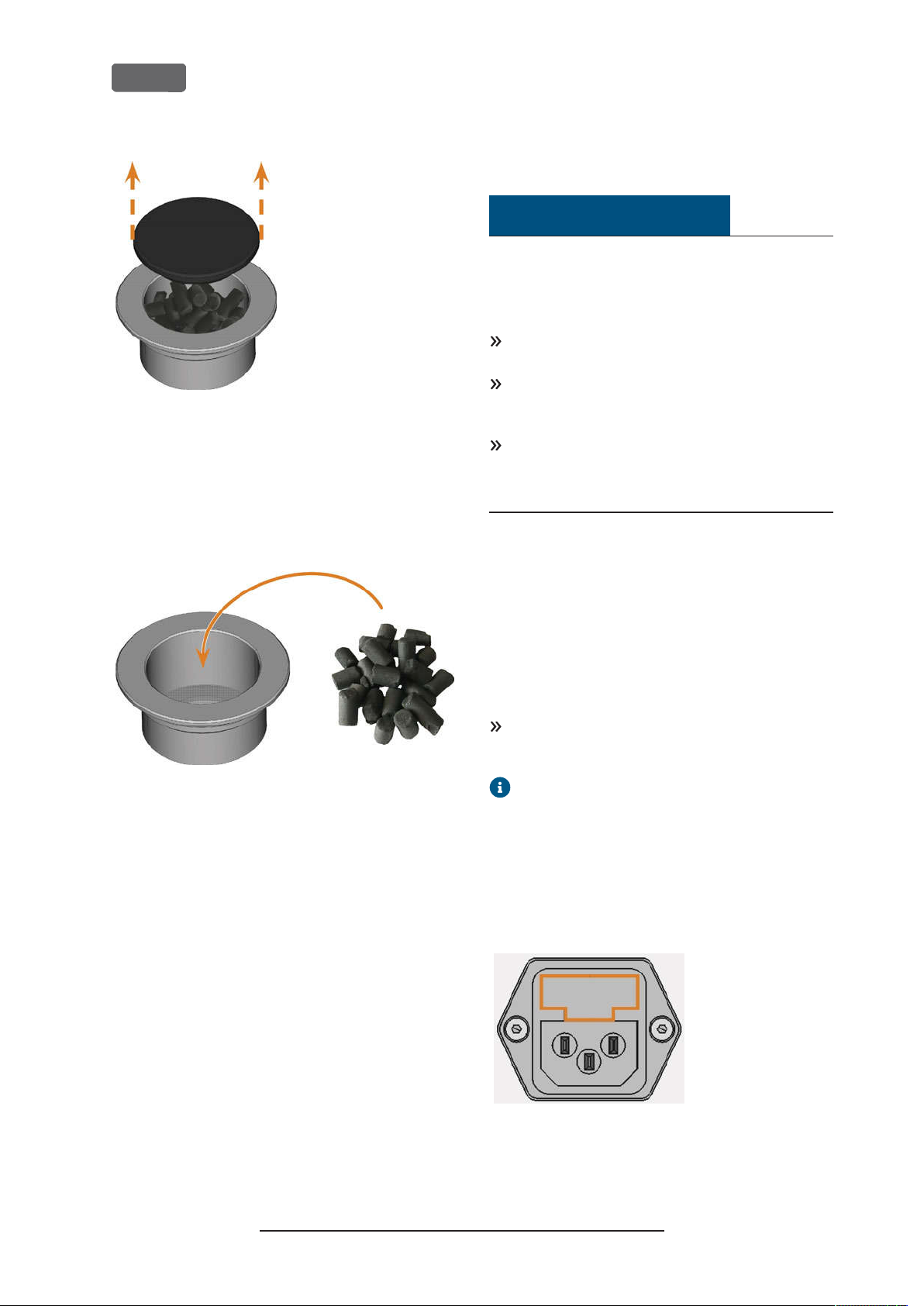
EN 64
FIG. 84 – O
6.
7.
8.
PENING THE CARBON FIL TER
Empty the filter and dispose of the activated carbon pellets.
Clean the carbon filter and dry it with a cloth.
Fill new activated carbon pellets into the carbon
filter.
Z4 – Maintenance and do-it-yourself
Cleaning the housing
NOTICE
Damaging of the housing when using an
unsuitable cleaning agent
If you use an unsuitable cleaning agent and/or
cleaning tool for cleaning the machine housing, the
surface or the adhesive foil can get damaged.
To avoid scratches, only use a microfiber cloth to
clean the housing.
Take care of the adhesive symbols so that they do
not peel off. The adhesive foil is especially sensitive to rubbing and strong cleaning agents.
If the usage of a special cleaning agent is necessary
to eliminate certain dirt, we recommend checking
the suitability of the cleaning agent at a hidden
place of the part first.
1.
Clean the surface with a dry microfiber cloth.
2.
If some dirt cannot be removed this way, moisten
the cloth. Use a pH neutral cleaning agent if
necessary.
FIG. 85 – R
9.
10.
11.
12.
EPL ACING THE ACTIVA TED CARBON PEL LE TS
Firmly close the carbon filter with the cap.
If the filter mesh is soiled, pull it off the cooling
liquid filter and rinse it under running water.
Reassemble the cooling liquid filter. Make sure
that the fine filter covers the complete filter.
Fill new cooling liquid into the tank.
Exchanging the main fuse
The internal power supply of the machine has a main
fuse that is accessible from the outside and can be
replaced if necessary.
As a replacement fuse, only use a fuse of the following type: T6,3A L250V
A new main fuse is available as spare part from
customer service.
1.
Switch off the machine at the main power switch.
2.
Remove the power cord from the connection
panel.
3.
Remove the cover of the fuse.
FIG. 86 – C
OVER OF THE FUS E(MARKED ORA NGE
Original Operating Instructions:Z4
Version: 12/5/2018
)
Page 65
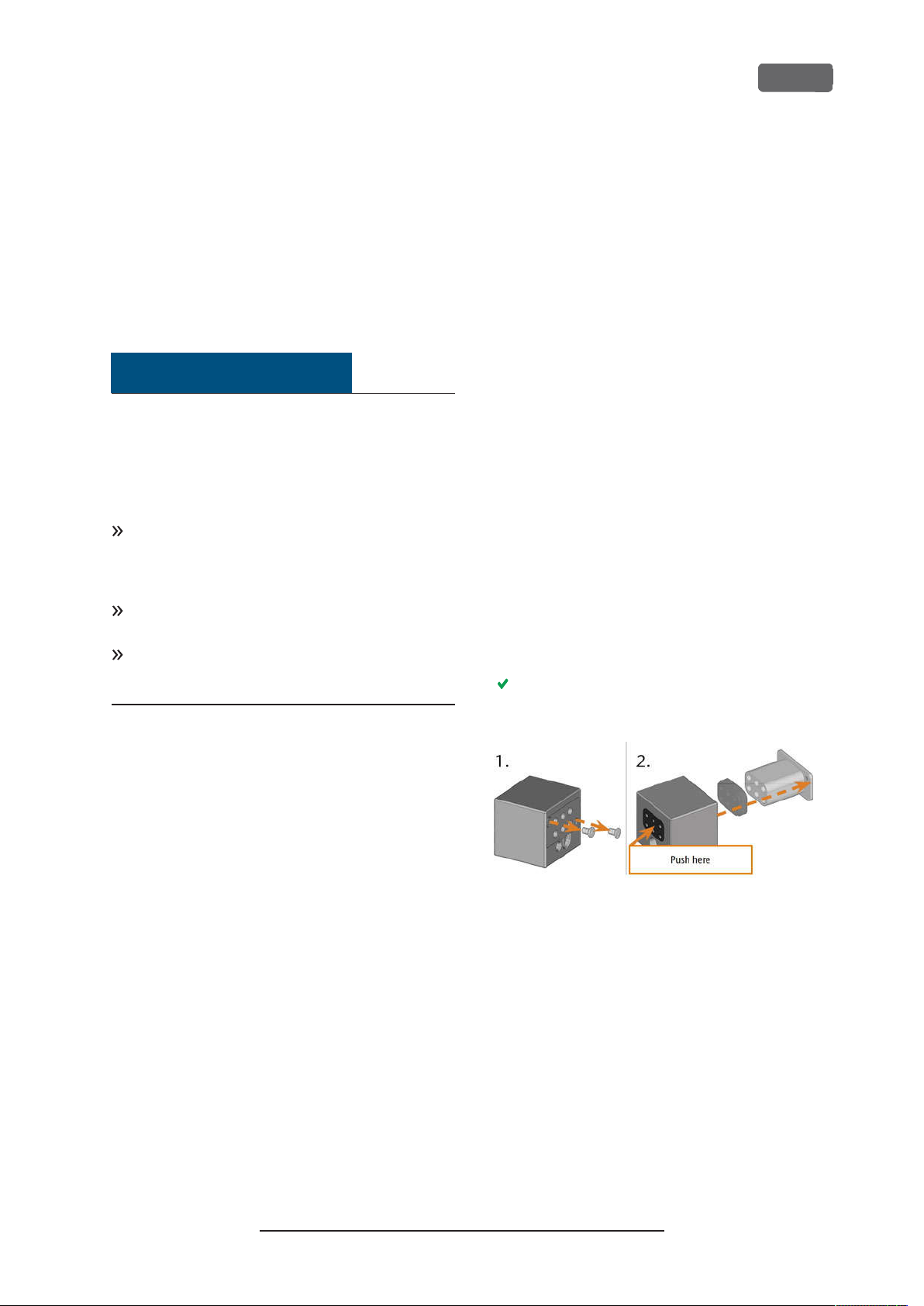
Z4 – Maintenance and do-it-yourself
4.
Remove the defective fuse and replace it with a
new fuse.
5.
If you do not have a replacement fuse ready, take
the replacement fuse from the right side of the
fuse cover and put it into the left side of the fuse
cover.
6.
Remount the fuse cover.
Calibrating the axes
NOTICE
Deterioration of machining results caused
by an incorrect calibration
At delivery, your machine is already calibrated. As
long as your machining results are accurate, a new
calibration is not necessary. A calibration takes much
time and will deteriorate the machining results if it is
improperly executed.
In case of inaccurate machining results, try adjusting the machining conditions first: Check the fixation and quality of the blank and the state of the
tool.
Before
service.
Be very careful
data during calibration. When in doubt, abort the
calibration.
calibrating the machine, contact customer
when measuring and entering
EN 65
Replacing the tool magazine
inserts
When tool magazine inserts are worn, they should be
replaced. New inserts are delivered without holes for
the tools. The holes must be drilled into the inserts
with the machine.
Your machine comes with tool magazine inserts
n
as spare parts and with the drill tool.
Additional inserts and drill tools are available via
n
customer service.
Customer service exchanges the tool magazine inserts
during preventive maintenance. If required, you can
exchange tool magazine inserts yourself and have
customer service drill the holes into the inserts via
remote maintenance.
You can replace tool magazine inserts as follows:
1.
Contact customer service. They will assist you
with drilling the holes into the new inserts. Otherwise, you wont be able to insert tools into the
tool magazines.
2.
Remove all tools from the desired magazine.
3.
Remove the screws from the bottom of the tool
magazine and put them aside.
4.
Firmly press against the tool magazine insert.
The insert moves out of the magazine together
with its retainer.
By calibrating the machine with test and calibration
specimens, it may be possible to improve the
machining results. Customer service will assist you
with this.
Your machine is delivered with a calibration set.
Customer service will need this set for calibration. It
contains the following parts:
Calibration blanks which are used to mill cal-
n
ibration and test specimens
A tool for milling the calibration or test spe-
n
cimens
A micrometer for measuring the machining pre-
n
cision
FIG. 87 – R
5.
6.
EMOV ING AN INSERT FROM A TOOL MAG AZINE
Insert the new insert into the magazine together
with its retainer. Position the insert with the
smooth side pointing forwards so that it forms an
even surface with the upper side of the tool
magazine.
Insert the screws and screw them down.
Original Operating Instructions:Z4
Version: 12/5/2018
Page 66

EN 66
Z4 – Maintenance and do-it-yourself
Exchanging the coupling of the
cooling liquid tank
1.
Empty the cooling liquid tank.
2.
Unscrew the filter in the cooling liquid tank with
your hand. Put the filter aside.
FIG. 88 – I
7.
NSE RTING AN INSERT INTO A TOOL MAG AZINE
Follow the instructions you receive from customer
service and drill the tool positions in the new
inserts.
FIG. 89 – T
POSITIONS
8.
9.
OOL MAG AZINE BEF ORE AND A FTER DRIL LING THE TOOL
Insert the tools into the correct positions of the
magazine (
page41
Ž
Inserting and exchanging tools
).
Ensure that the correct tool magazine for the next
job is mounted (
magazines
Ž
Mounting exchanging tool
– on page43
).
– on
FIG. 90 – U
3.
NSCREWING THE FILTER IN THE COOLING LIQUID TA NK
Push the coupling out of the tank.
FIG. 91 – P
4.
USHING THE COUPL ING OUT OF THE TANK
Thoroughly clean the cooling liquid tank. Especially clean the sealing surface around the opening for the coupling.
If the surface around the opening for the
coupling is soiled, the sealing ring on the
coupling will not properly seal the tank
and liquid will leak.
Original Operating Instructions:Z4
Version: 12/5/2018
Page 67
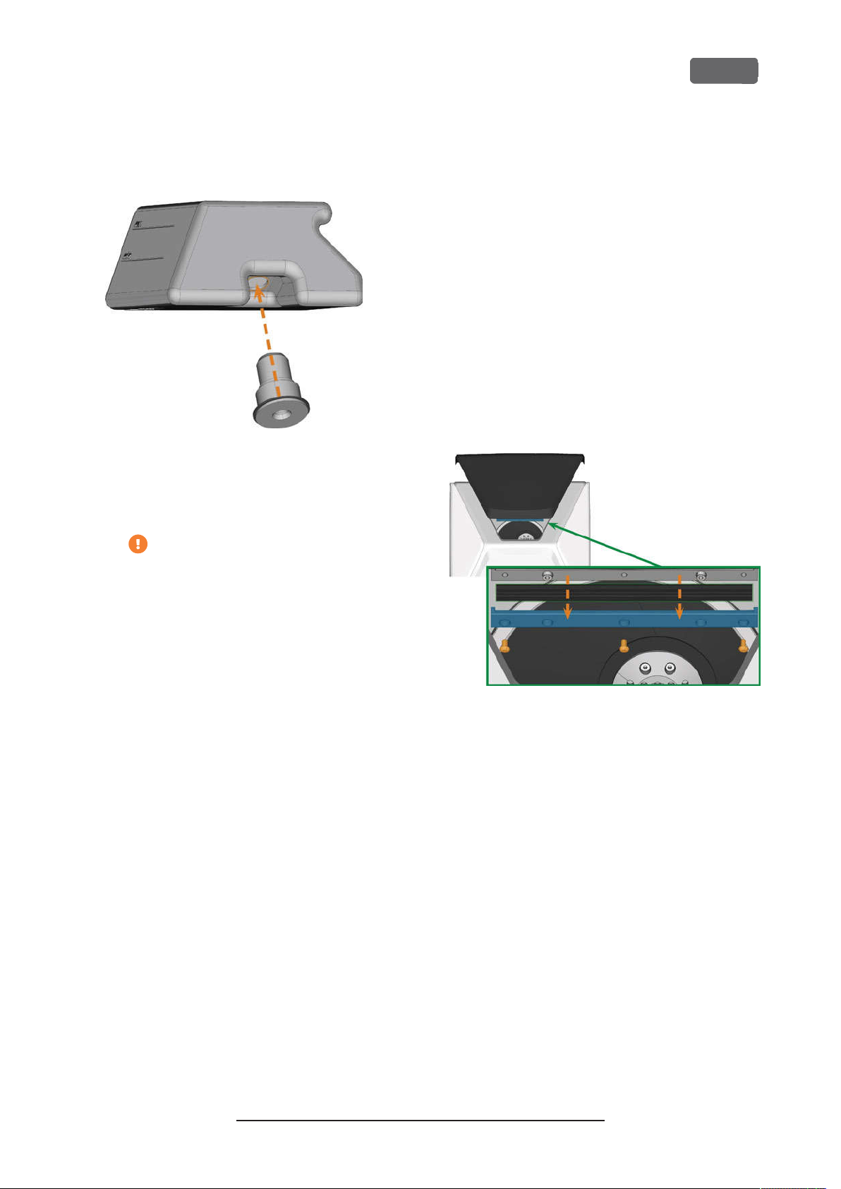
Z4 – Maintenance and do-it-yourself
5.
Insert the spare coupling into the designated
opening as shown in the following figure.
FIG. 92 – I
LIQUID TANK
NSE RTING THE SPARE COUPLING INTO THE COOLING
EN 67
Exchanging the view window
wiper
The view window wiper removes liquid from the back
of the view window when the working chamber door
opens and closes. You need to exchange it according
to the interval given in the maintenance table or when
the wiping effect is too low.
The view window wiper is fixated by a two-part
holder.
You exchange the view window wiper as follows:
1.
Open the working chamber door.
2.
Unscrew the 3 screws (marked orange in the following figure) that attach the lower part of the
holder to the upper part. Remove the lower part
of the holder (marked blue in the figure).
6.
Screw down the filter onto the coupling with your
hand. Do not tighten the filter completely yet.
If you tighten the filter now, you may
damage the new coupling when you
attach the tank to the machine. As a result,
the coupling will no longer be water tight.
7.
Reinsert the cooling liquid tank until the tank is
properly attached to the machine.
8.
Pull the cooling liquid tank out of the machine
again.
9.
Tighten the filter completely.
10.
Fill new cooling liquid into the tank.
FIG. 93 – R
MACHINE
3.
4.
5.
EMOV ING THE VIEW WINDOW WIPER FROM THE
Remove the view window wiper from the holder
and dispose of it.
Clean the holder of the view window wiper with
a wet cloth. Clean the part that you removed and
the upper part in the machine.
Put the spare view window wiper into the lower
part of the holder according to the following figure.
Original Operating Instructions:Z4
Version: 12/5/2018
Page 68
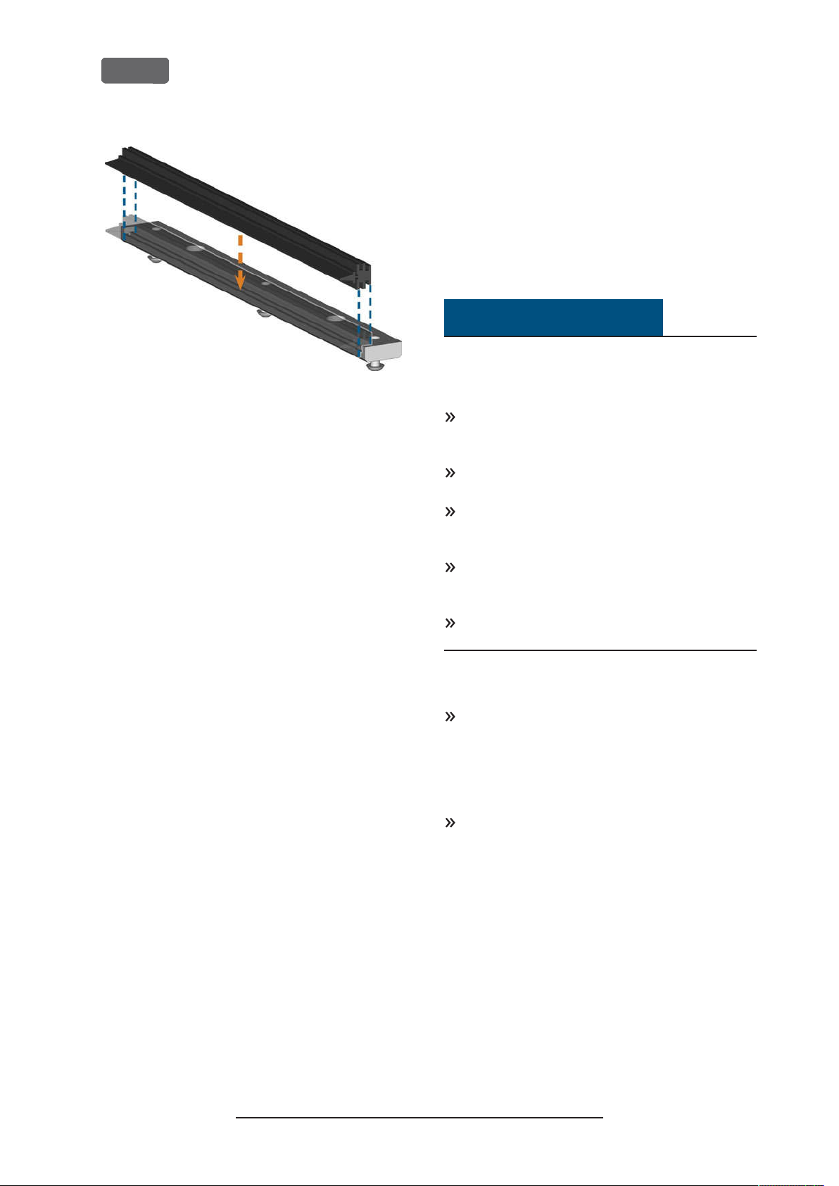
EN 68
FIG. 94 – P
6.
7.
OSITIONING THE SPARE VIEW WI NDOW WIPE R
Place the lower part of the holder on the upper
part in the machine with the wiper lying between
the two parts. Hold it in place.
Screw down the holder with the 3 screws.
Z4 – Maintenance and do-it-yourself
Updating the software and firmware
Updating the firmware of the machine
The firmware is the internal control software of your
machine. New versions may introduce new functions
and improve existing ones. New firmware versions
come as part of new versions of DentalCNC.
NOTICE
Damaging of the control unit when a
firmware update is interrupted
If the firmware update is interrupted, the control unit
of the machine may become permanently damaged.
Only update the firmware if a permanent electrical
supply of the machine and the computer is guaranteed.
Only update the firmware if the computers operating system is stable and is free of malware.
Only update the firmware if the connection
between the computer and the machine is stable.
Always use a wired connection during the update.
Do not disconnect the machine or the computer
from the electrical source nor switch off the
machine or computer during a firmware update.
Do not close DentalCNC during a firmware
update.
Only customer service can currently update the firmware.
If a firmware update is available, contact customer
service.
Updating DentalCAM DentalCNC
Only customer service can currently update the
internal CAM computer.
If you require an update for DentalCAM
DentalCNC, contact customer service.
Original Operating Instructions:Z4
Version: 12/5/2018
Page 69
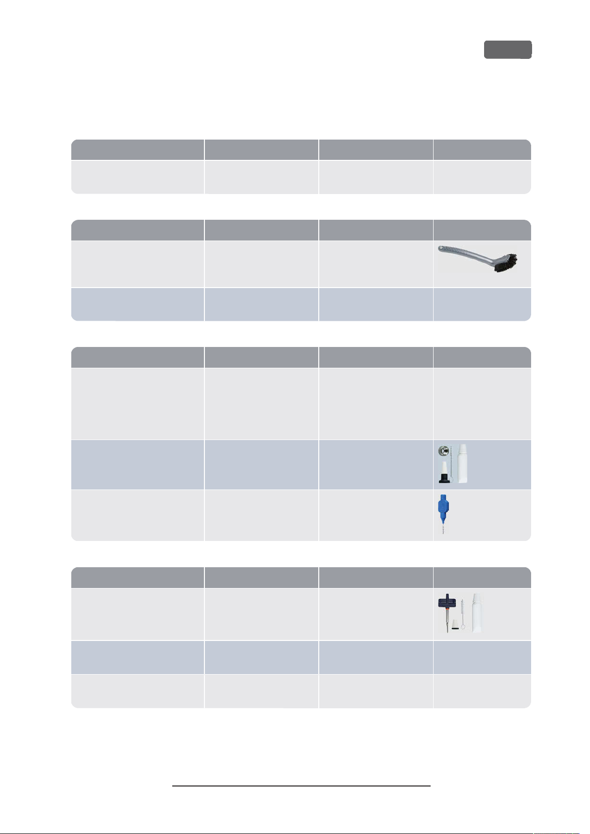
Task Recommended interval Procedure / Parts Tool illustration
Task Recommended interval Procedure / Parts Tool illustration
Task Recommended interval Procedure / Parts Tool illustration
Task Recommended interval Procedure / Parts Tool illustration
Z4 – Maintenance and do-it-yourself
Maintenance table
Several times per day
Checking the cooling liquid If the flow rate is insufficient Visual check; exchange liquid
if necessary
Once per day
EN 69
Exchanging the cooling liquid and
cleaning the tank
Ž
page 38
(
)
Daily cleaning of the working
Ž
chamber (
page 57
)
Once per week
Weekly cleaning of the working
Ž
chamber (
page 57
)
Cleaning the collet chuck
Ž
page 58
(
)
Cleaning the nozzle plate
page 60
Ž
(
)
3 operating hours
After work
After work
If soiled
Once per week
If soiled
If tool magazines are no
longer recognized or move
sluggishly when mounted
Once per week
In case of rotational imperfections
Once per week
In case of irregular spray
patterns
Brush, Water, Cooling liquid
Wet cloth
Wet cloth, Dry cloth, Brush,
Collet chuck grease
Spindle service set, Collet
chuck grease, Interdental
brush
Interdental brush
Every 4 weeks
Cleaning the collet chuck of the
blank holder
page 60
Ž
(
Rinsing the cooling liquid system
Ž
(
page 62
)
)
Exchanging the carbon filter
Ž
page 63
(
)
Every 4 weeks
Blank holder service set
In case of bad machining
results
Every 4 weeks
If the flow rate is insufficient
Every 4 weeks Exchange after rinsing the
cooling liquid system
Original Operating Instructions:Z4
Version: 12/5/2018
Page 70
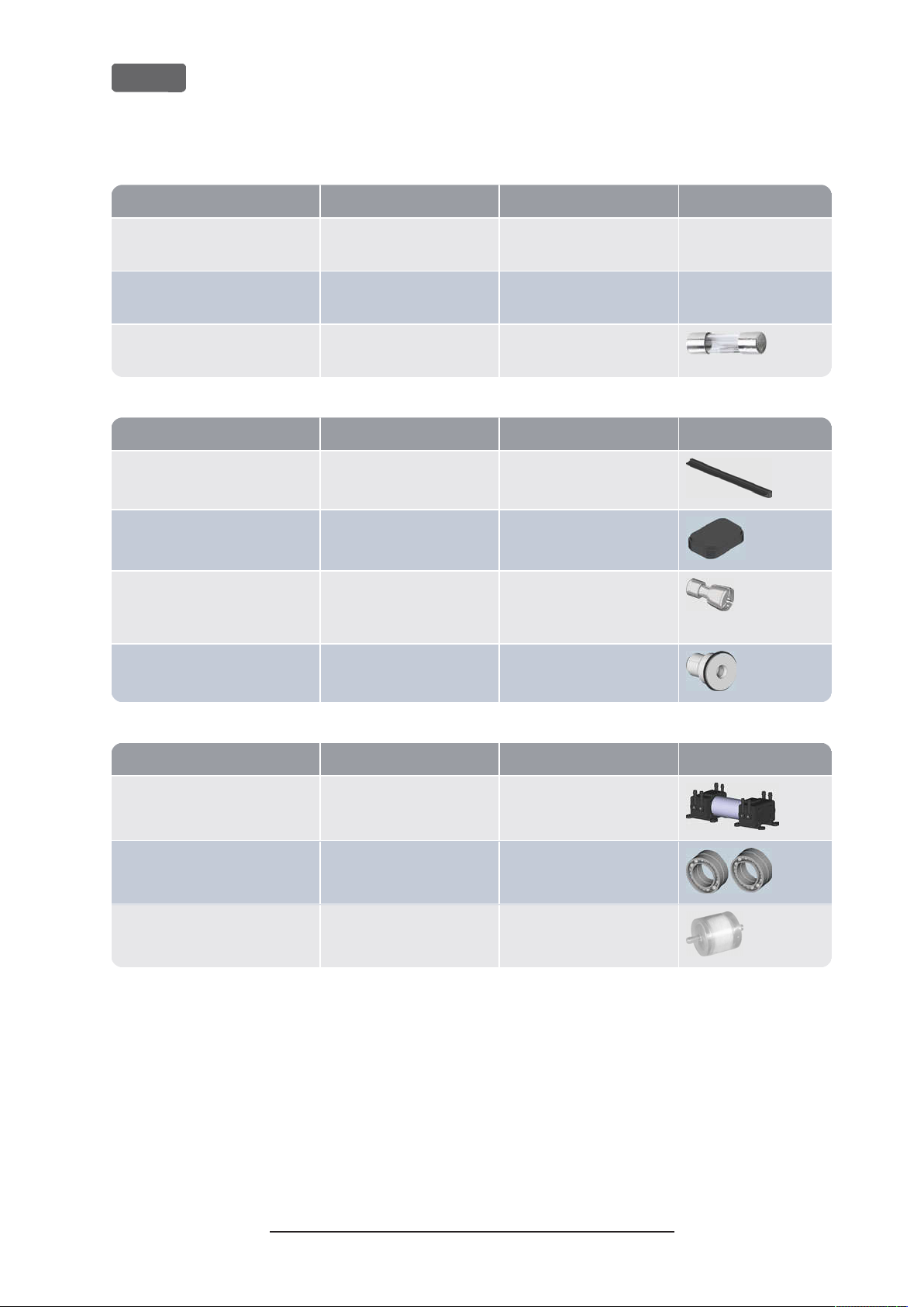
Task Recommended interval Procedure / Parts Spare part illustration
Wear part Recommended interval Procedure / Parts Spare part illustration
Wear part Recommended interval Procedure / Parts Spare part illustration
EN 70
When necessary
Z4 – Maintenance and do-it-yourself
Updating the software and firmware
Ž
page 64
(
)
When an update is available
Cleaning the housing
Ž
page 64
(
)
Exchanging the main fuse
Ž
page 64
(
)
Wear parts that you can exchange yourself
View window wiper
Ž
page 67
(
)
Tool magazine inserts
Ž
page 64
(
)
Collet chuck (Blank holder)
page 60
Ž
(
)
Coupling of the cooling liquid tank
Ž
page 66
(
)
200 operating hours
1,000 operating hours
Every 2 years
*
1,000 operating hours
Every 2 years
*
1,000 operating hours
Every year
*
Microfiber cloth, Water, Mild
cleaning agent (optional)
Replacement fuse T6,3A L250V
*
*
*
Blank holder service set;
remove and insert collet chuck
as when cleaning it
*
Wear parts that customer service exchanges for you
Cooling liquid pump 1,000 operating hours
Spindle bearings(requires spindle
1,000 operating hours
*
*
exchange by customer service)
Air intake filter 1,000 operating hours
*
These are recommendation guidelines. Depending on the processing material and how well the machine is cleaned, these
*
values may differ.
Original Operating Instructions:Z4
Version: 12/5/2018
Page 71

Z4 – Disposal
EN 71
9 Disposal
Disposing of the cooling liquid
When disposing of the cooling liquid/ machining
residues, obey the following regulations.
Avoid entry of hazardous machining residues into
the soil, water or into sewers.
Obey the national and local laws of the disposal
location in any case.
If necessary, have the cooling liquid and machining residues disposed of by an approved disposal
company.
Keep a reference sample of the disposal product
for at least 6 months.
If you dispose of the coolingliquid yourself, do as
follows:
a.
Completely filter the machining residues out of
the used cooling liquid.
b.
Dispose of the liquid via the sewers.
c.
Dispose of the solid machining residues as
described by the manufacturer of the material.
Copyright
Distribution or duplication of all content is only
allowed by written consent of vhf camfacture AG. This
includes reproduction by presentation and broadcasting.
This document is published by:
vhf camfacture AG
Lettenstraße 10
72119 Ammerbuch, Germany
dentalportal.info
Disposing of the machine
The machine must not be disposed of with the
residual waste.
We will dispose of the machine at no cost. The
owner will bear the costs for disassembly, packaging
and transport.
Before sending in the machine for disposal, contact customer service.
If you dispose the machine yourself, obey by the
national and local laws of the disposal location.
Dismantling, transport and packaging
Ž
page 9
Original Operating Instructions:Z4
Version: 12/5/2018
Page 72

EN 72
10 Troubleshooting
In case something is not working as intended, take a
look at the following troubleshooting guide.
NOTICE
Z4 – Troubleshooting
3.
If the working chamber lighting does not illuminate, check if the power cable is properly
seated in the machine and is connected to the
electrical source.
4.
If the machine is not powered, perform an emergency opening when necessary.
Machine damage due to improper
troubleshooting
In case of improper troubleshooting, your machine
may get damaged.
If you are unsure of how to perform certain steps
during troubleshooting or cannot solve the problems, abort the troubleshooting and contact customer service.
Additional symbols in this chapter
Question to narrow down the problem
Suggested solution
I cannot open the working chamber door
Is the machine operating?
While the axes are moving, you cannot open the
working chamber door.
If applicable:
Wait until the machine has finished.
Has a power failure occurred at the install-
ation site of the machine?
If applicable:
Depending on the duration of the power failure,
restart the machine or perform an emergency
opening.
Is electricity available at the installation site
of the machine?
If applicable:
1.
Connect the machine to the electrical source.
2.
Switch on the machine at the main power switch.
3.
If the working chamber lighting does not illuminate, check if the power cable is properly
seated in the machine and is connected to the
electrical source.
4.
Try connecting the machine to a different socket.
Is the door blocked?
If applicable:
1.
Check if the guide rails at the back of the working
chamber door are free from dirt.
2.
Switch on the machine at the main power switch.
I have installed all components, started the
software but the machine does not
reference
Is the working chamber door open?
The machine does not reference with the working
chamber door open.
If applicable:
Confirm the corresponding dialog on the touchscreen to close the door.
Is an Ethernet cable connected to the
machine?
If applicable:
Check if the Ethernet cable is properly seated in
the connector and is undamaged. If possible, use
the provided cable.
Do you use WiFi?
If applicable:
Check if the access point is properly set up and
operational.
Is the working chamber illuminated in red?
In this case a machine malfunction occurred.
If applicable:
1.
Restart the machine.
2.
If the working chamber continues to be illuminated in red, contact customer service.
My machine doesnt execute any jobs
although it is connected to the computer
Is the drawer open?
If applicable:
Push the drawer into the machine until it snaps in
place.
Is the wrong tool magazine mounted or didnt
the machine recognize the magazine?
If applicable:
In the
1.
which tool magazine is required and if the
machine has recognized it (green check mark in
the check box).
section of the touchscreen, check
Jobs
Original Operating Instructions:Z4
Version: 12/5/2018
Page 73

Z4 – Troubleshooting
EN 73
2.
If there is no green check mark, follow the instructions for inserting tool magazines.
3.
If there is no green check mark although the
correct tool magazine is mounted, clean the
magazine and the tool magazine holder.
The machining results are not satisfactory
and / or tools keep breaking
Do the tool positions in the Tools section
correspond to the tools in the respective tool
magazine?
If not, the machine uses the wrong tools during job
execution.
How to check this:
1.
Via the touchscreen, compare the tool positions
in the
responding tool magazine.
2.
Replace the wrong tools in the tool magazine
with the correct ones.
Is the blank properly mounted?
How to check this:
Remove the blank and remount it. The groove of
blocks has to properly sit on the corresponding
positioning pin.
Are bolts, fixing mechanisms, gaps and openings of the blank holder contaminated by
processing dust?
If applicable:
Clean the mentioned components thoroughly.
Is the measuring key contaminated?
If applicable:
Clean the measuring key with a brush.
section with the tools in the cor-
Tools
Do the parameters of the job in the software
correspond to the parameters of the blank?
How to check this:
Make sure that the following parameters of the job
and of the blank in the machine correspond to
each other. Also make sure that they are suitable
for the objects that you want to machine.
Material type
n
Blank dimensions
n
Indications (types) of the individual objects
n
Are the object files of sufficient quality?
How to check this:
1.
Check the quality of object files (STL files) in your
CAD application or an STL viewer. Especially, consider the manufacturer information on wall thickness and border thickness.
2.
If necessary, adjust the settings of your scanner
and scan application.
Is the collet chuck of the spi ndle contaminated
or is it loosely seated in the spindle?
If applicable:
1.
Clean the collet chuck with the provided spindle
service set.
2.
When you insert the collet chuck into the spindle,
make sure that it is properly seated.
Did you exchange the collet chuck at the
recommended interval?
How to check this:
Verify the recommended interval for exchanging
the collet chuck in the maintenance table. If necessary, exchange the collet chuck.
Are the tools worn?
How to check this:
1.
Visually inspect all tools.
2.
Check the tool life values via the touchscreen.
3.
Replace worn tools with new ones.
Do rings on the tools sit in the groove on the
tool shank?
How to check this:
Visually inspect all tools and push rings that have
moved into the groove again.
Are the tool magazine inserts worn?
If applicable:
Replace the tool magazine inserts with new ones.
Original Operating Instructions:Z4
The machine displays that the flow rate is
too low
Is cooling liquid lacking in the tank? Is the
cooling liquid soiled?
If applicable:
Clean the tank. Fill in clean cooling liquid.
Is the filter in the cooling liquid tank
clogged?
If applicable:
Clean the filter and the tank. Fill in clean cooling
liquid.
Are the liquid nozzles in the working chamber
clogged?
If applicable:
Clean the nozzles with the inter-dental brush.
Version: 12/5/2018
Page 74

EN 74
I have exchanged the tool magazine inserts
and now there are no holes for the tools
anymore
Tool magazine inserts are delivered without drilled
holes for tools. You drill them with the machine.
Contact customer service.
Z4 – Troubleshooting
Original Operating Instructions:Z4
Version: 12/5/2018
Page 75

Index
EN 75
B
Back panel cover
Blocks
Mount/remove
.....
.....
52
46
C
Collet chuck
Color codes
Compressed air
Insufficient
Cooling liquid
Exchange
Requirements
Cooling liquid tank
Clean
Exchanging the coupling of the cooling liquid tank
66
.....
.....
.....
.....
38
58, 60
41
.....
38
.....
50
38
D
Definition of wear parts
Dental Wings Chairside CAD
Disposal
.....
Machine
71
.....
71
.....
53
.....
28
E
Electric connection
Emergency opening
exocad ChairsideCAD
.....
.....
.....
18
51
27
F
FAQ
72
.....
Firmware update
Frequently Asked Questions
Front side of the machine
.....
68
.....
.....
72
10
H
Home section
.....
36
.....
I
Implants
Regulations
Installation
Site
.....
.....
16
15
.....
8
J
Job interruption
Jobs
Cancel
.....
Start
.....
Jobs section
47
.....
49
.....
37
49
M
Machine
Malfunction
Shut down
Start
.....
Start processing
Start with tool in collet chuck
Machine location
Main fuse
Maintenance
Maintenance section
Maintenance table
Manufacturing software
Measuring key
.....
Cleaning the collet chuck
Cleaning the collet chuck of the blank holder
Cleaning the housing
Cleaning the nozzle plate
Cleaning the working chamber
Exchanging the main fuse
General information
Preventive maintenance
Replacing the tool magazine inserts
Rinsing the c ooling liquid system
Wear parts
31
64
.....
.....
.....
.....
.....
8
.....
57
33
53
.....
50
.....
.....
16
69
47
.....
54
.....
.....
.....
64-65
.....
.....
53
.....
8
.....
58
60
.....
64
53
.....
32
57
.....
62
65
.....
60
Original Operating Instructions:Z4
Version: 12/5/2018
Page 76

EN 76
Index
Multi-purpose drawer
Emergency opening
Open/close
Overview
.....
.....
35
12
N
Nozzle plate
.....
60
O
Operating temperatures
P
Power connection
Power failure
Prefabricated abutments
Regulations
Preventive maintenance
.....
.....
.....
50
8
R
Rear side of the machine
Repackaging
.....
9
18
.....
.....
.....
.....
53
52
16
10
Maintenance section
Overview
Sections
Start jobs
Tools section
Transport
Transport lock
TRIOS Design Studio
Troubleshooting
.....
.....
.....
.....
9
.....
36
36
47
.....
18
.....
U
Unattended operation
User interface
Overview
.....
36
W
Wear parts
Working chamber
Clean
Working chamber door
.....
.....
53
.....
57
38
.....
72
11
.....
.....
25
.....
54
8
11
S
Scope of delivery
Sound emission
Spindle
.....
Storage
.....
Strainer basket
.....
.....
8
9
38
.....
T
Technical data
Temperatures
Tool breakage
Tool magazine
Color codes
Letters
Tool magazine inserts
Tools section
Touchscreen
Cancel jobs
Home section
Jobs section
.....
.....
.....
.....
.....
.....
.....
41
.....
14
16
50
43
.....
38
11
.....
.....
49
12
41
37
15
.....
36
65
Original Operating Instructions:Z4
Version: 12/5/2018
 Loading...