

Page 1

TAJFUN 1000
INSTRUCTION MANUAL
www.italab.sk
www.kenwood.sk
Page 2

________________________________________________________________________________
Page 2 of 10 VH Electronics Slovakia www.italab.sk
Acknowledgment
Thank you for purchasing Power linear amplifier TAJFUN 1000 144 from VH Electronics. During its
productiom, we used the latest knowledge in the field of VHF Power amplifiers and the most
advanced technology in the management, communication and display systems. We believe that our
product will exceed your expectations and will be working properly to your satisfaction. Please take a
few moments to read this manual and get acquainted with this device.
I. GENERAL INFORMATION
I.1 Description
TAJFUN 1000 144 is a small, lightweight but robust LDMOS VHF Power Amplifier (hereafter
PA) working in amateur 2m band with output power up to 1kW.
I.2 Technical parameters
Frequency Coverage 142 - 146 MHz Amateur band
Operating Mode FM, SSB, CW, DIGI
Output Power 1000W CW, 800W SSB ( lineary ), 700W FM and DIGI
Input Power 8 - 9W ( Inside 3dB hybrid attenuator )
Power Gain Typically 20dB
LDMOS MRFE6VP61K25H ( 1250W ) Freescale
PUSH PULL Configuration
Class Operating AB
Input / Output Impedance 50 Ω Connector 2 x N-female
Suppression of harmonics ≤70 dBc (Low Pass Filter)
Intermodulation distortion -32 dBc
Cooling 2 axial fans PA + 1 fan Power Supply
Power Supply Inside Input: 85 - 300VAC, 45 - 66Hz
Output: 48VDC / 1800W
Working temperature 0 - 45°C, Max. Humidity 90%
Dimension 266 x 105 x 294mm ( width x height x depth )
Weight 5,5kg
Coaxial Relay CX600NC – CX140D
Page 3
________________________________________________________________________________
Page 3 of 10 VH Electronics Slovakia www.italab.sk
I.3 Protection, measurements and display
Protection PWR, REF, Temperature, Imax, Umax/Umin
Control / Display Colour TFT display
Measurements and display:
o Drain Current
o DC Voltage
o Output Power PWR
o Reflected Power REF
o Peak Power PEP
o Temperature
I.4 Put into operation
If your device was transported or stored in a cool or cold environment, it is necessary to unzip it
first and let it dry in a warm enviroment (by doing this you will protect your device against a
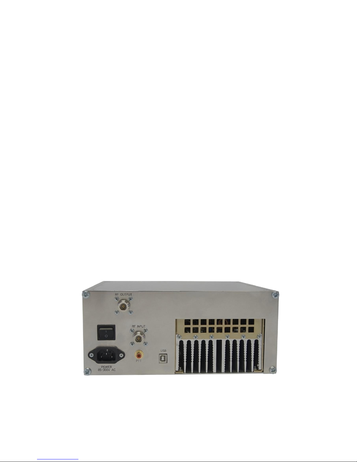
possible water condensation). Then you should connect the connecting coaxial cable to the RF
INPUT and RF OUTPUT jacks on the rear panel (N-female connector) and attach the PTT RCA
(CINCH) connector. Broadcasting (Tx) is active when connected to GND.
Back panel
Page 4

________________________________________________________________________________
Page 4 of 10 VH Electronics Slovakia www.italab.sk
Insert a supplied power cord into the POWER. Then turn on the power switch. Initializing and
control equipment starts. After a short time, the fans will turn for a moment at a full speed and
then, after a while, they reduce into low speed according to the current temperature of the
LDMOS transistor. Finally, it performs the initialization of the TFT touch screen and it displays:
Basic menu - “Home QSO“ , “Contest QSO“
By pressing an icon on the screen we select:
I.4.1 Mode Home QSO
This mode is suitable for the standard operation of the Home for the occasional QSO with less
demand for cooling of the PA. Speed cooling fans are continuously controlled (PWM) according
to the temperature of the LDMOS transistor independently of the control of the PTT (Rx/Tx
mode). Advantage – quiet operation.
I.4.2 Mode Contest QSO
This mode is suitable for the Contest, eventually for DIGI operation with high demands on
cooling of the PA. After switching of the PTT (Tx mode) it switches the maximum speed of the
cooling fans. After switching off the PTT (mode Rx) the speed is continuously controlled (PWM)
according to the temperature of the LDMOS transistor. Advantage - powerful cooling for
demanding operations.
After selecting the operating mode we will get to the menu for Display operation.
In this menu, the PA does not respond to control PTT. Coaxial relays RF INPUT linking
directly to the RF OUTPUT connector (bypass the amlifier). This mode ideal for local
QSOs at low power wihout having to disconnect the PA.
Page 5

________________________________________________________________________________
Page 5 of 10 VH Electronics Slovakia www.italab.sk
By pressing on the Icon, you can choose from the following views:
o Standard
o Bargraph
o Peak
o All values
I.4.3 Standard
It shows the performance of the Output Power - PWR, Reflected Power – REF, both
appears in a bargraph and their values are represented in a numerical form + it shows the
values of the Temperature, Current and Voltage
Mode Rx Mode Tx
I.4.4 Bargraph
It shows the performance of the Output Power - PWR, Reflected Power - REF and the
Temperature – TEMP; they are all shown in a bargraph and their values appear in
numerical form
I.4.5 Peak
It displays values as Standard, but PWR PEP and REF PEP are displayed in the peek
values and the maximum values are represented during the hold of the PTT (Tx mode)
Page 6

________________________________________________________________________________
Page 6 of 10 VH Electronics Slovakia www.italab.sk
I.4.6 All values
It displays values as Standard. PWR PEP and REF PEP are displayed in the peak value
and the maximum value are represented during the hold of the PTT (Tx mode) + it shows
the values of the Coupler U PWR and U REF [mV] for servicing.
I.5 Responding in excessing the parameters Alert / Block-Warning
I.5.1 Output Power PWR
Alert - when crossing PWR above the set value (≥1000W) it gets into a red bargraph, the
numeric value turns red and the buzzer beeps
Block - when crossing PWR above critical value (≥1100W) it declares "Warning" on the
display and it blocks the LDMOS (Inhibit -5V), it turns the coax relay off and it blocks the
PTT.
In order to restore operation it is necessary to “Restart“ – confirm “Warning“ and return to
the Display operation
Alert Block - Warning
Page 7

________________________________________________________________________________
Page 7 of 10 VH Electronics Slovakia www.italab.sk
I.5.2 Reflected Power REF
Alert - when crossing PWR above the set value (≥100W) it gets into a red bargraph, the
numeric value turns red and the buzzer beeps
Block - when crossing REF above critical value (≥110W) it declares "Warning" on the
display and it blocks the LDMOS (Inhibit -5V), it turns the coax relay off and it blocks the
PTT.
In order to restore operation it is necessary to “Restart“ – confirm “Warning“ and return to
the Display operation
Alert
I.5.3 Temperature
Alert - when crossing the temperature above the set value (≥65°C) it gets into a red
bargraph, the numeric value turns red and the buzzer beeps
Block - when crossing PWR above critical value (≥70°C ) it declares "Warning" on the
display and it blocks the LDMOS (Inhibit -5V), it turns the coax relay off and it blocks the
PTT.
In order to restore operation it is necessary to “Restart“ – confirm “Warning“ and return to
the Display operation
Alert
Page 8

________________________________________________________________________________
Page 8 of 10 VH Electronics Slovakia www.italab.sk
I.5.4 DC Voltage
Alert - when crossing DC Voltage above the set value (≥50V) the numeric value turns red
and the buzzer beeps
Block - when crossing DC Voltage above critical value (≥55V ) it declares "Warning" on
the display and it blocks the LDMOS (Inhibit -5V), it turns the coax relay off and it blocks
the PTT.
In order to restore operation it is necessary to “Restart“ – confirm “Warning“ and return to
the Display operation
Alert
I.5.5 Drain Current
Alert - when crossing Current above the set value (≥31A) the numeric value appears red
and the buzzer beeps
Block - when crossing Current above the critical value (≥35A ) it declares "Warning" on
the display and it blocks the LDMOS (Inhibit -5V), it turns the coax relay off and it blocks
the PTT.
In order to restore the operation it is necessary to “Restart“ – confirm “Warning“ and
return to the Display operation
Alert
Page 9

________________________________________________________________________________
Page 9 of 10 VH Electronics Slovakia www.italab.sk
BLOCK DIAGRAM
Page 10

________________________________________________________________________________
Page 10 of 10 VH Electronics Slovakia www.italab.sk
I.6 Sequencer
I.6.1 Time control coaxial relay
Control unit „Control Board“ switch input and output coaxial relays in the correct time
sequence according to the PTT signal. Time T1 and T2 can be changed using
the software Service Tajfun 1000 via USB port PA.
http://www.italab.sk/index.php/sk/ham-radio/tajfun-1000-144-mhz-2382013-11-15-08-1632_-detail
Normally set times:
T1 (Relay IN) ...... 20ms
T2 (Relay OUT)... 25ms
ATTENTION !!! Carefully consider any change in these times not to cause
destruction LDMOS or accident PA.
 Loading...