

VGuard N series User Manual
VGuard N Series
16/8/4 Channels Embedded Net DVR
User’s Manual
Please read this user’s manual carefully before you use this system.
Please keep a user’s manual handy when needed.
Declaration:
All the specification mentioned in this user’s manual is
based on the products when this user’s manual is
published. Manufacturer owns the right to alter or change
this product with or without notification. All the products
specification will base on the product itself.
2
Chapter 1 : System Specification..................................... 6
1.1 System Hardware Specification: ..................................................6
1.2 System Function Specification:....................................................7
1.3 Package Content:.........................................................................8
Chapter 2 : System Introduction:..................................... 9
2.1 System Front Panel:.....................................................................9
USB…………………………………………………………………………….9
Number 1-8 Buttons................................................................................9
Number 9 Button...................................................................................10
Number 0 Button...................................................................................10
Power Indicator( ) ......................................................................10
Recording Indicator( ).................................................................10
Playback Indicator( )...................................................................10
Record/ Switch to Recording Display Button:.................................10
Setting / List Button......................................................................10
Leftward Button / Playback Backward...........................................11
Upward button / Step Playback / Pause Playback ...................11
Rightward Button / Playback Forward / Output Control........11
Select / Backup Button........................................................11
Playback Button .............................................................................11
Subtract 1 / Next / Slow Speed Playback.......................................12
Downward Button / PIP Function.............................................12
Add 1 / Last One / Fast Speed Forward .........................................12
Cancel / Stop / Alarm Log Button...............................................12
3
2.2 System Back Panel: ...................................................................13
Power Supply........................................................................................13
Ethernet RJ45-jack................................................................................13
USB……………………………………………………………………………13
Power…………………………………………………………………………13
VGA Output...........................................................................................13
Video Input BNC-jacks..........................................................................13
TV Monitor Output BNC-jack.................................................................14
Audio Input RCA-jack............................................................................14
Audio Output Earphone-jack.................................................................14
Input Terminals (Optional) .....................................................................14
Output Terminals (Optional) ..................................................................14
2.3 Hard Disk Installation:.................................................................14
Chapter 3 : System Setting..............................................15
3.1 Setup Main Menu .......................................................................15
3.2 Time / Display Setup ..................................................................16
3.3 Camera Setup ............................................................................17
3.4 Alarm Setup................................................................................18
3.5 System Setup.............................................................................20
3.6 Network Setup............................................................................21
Server Setup:........................................................................................21
Connection............................................................................................22
WAN Mode............................................................................................23
DIAL-UP Mode......................................................................................24
DNS Setup............................................................................................24
DDNS Setup .........................................................................................25
User…………………………………………………………………………..26
Network Info..........................................................................................27
3.7 Input /Output Setup: (Optional) ..................................................27
Output...................................................................................................28
S.M.A.R.T.(Smart Monitoring, Analysis, and Reporting Technology).....28
Input…………………………………………………………………………..28
4
3.8 Program......................................................................................29
3.9 Advanced Setup.........................................................................30
Chapter 4 : Record .......................................................... 31
4.1 Activate Record Manually...........................................................32
4.2 Auto Record................................................................................33
4.3 Stop Record................................................................................33
Chapter 5 : Playback....................................................... 33
5.1 Assign Time for Playback...........................................................34
5.2 Date List for Playback:................................................................34
5.3 Playback Operation Buttons.......................................................35
Chapter 6 : PIP Function................................................. 36
6.1 PIP Sub-Window Location Adjustment.......................................36
Chapter 7 : Alarm Log..................................................... 37
Chapter 8 : I/O…………………………………………………38
8.1 Input Control Setup.....................................................................38
8.2 Output Control Setup..................................................................39
8.3 Output Control............................................................................39
Chapter 9 : File Backup................................................... 40
Chapter 10 : Network Function ........................................ 41
10.1 Network Setup:...........................................................................42
10.2 Network Connection Setup:........................................................43
10.3 Remote File Search:...................................................................48
10.4 Remote VGuard N series using IE browser ...............................49
Chapter 11 : VG Player...................................................... 58
11.1 Playback Control Panel:.............................................................59
11.2 Search ........................................................................................61
11.3 Color Configuration.....................................................................61
11.4 Motion Search Setup..................................................................62
11.5 Continuous Playback..................................................................62
5
11.6 Caption Display Setup................................................................62
11.7 VG to AVI Conversion: ...............................................................63
Chapter 1 : System Specification
VGuard N series is a new generation embedded DVR system. This system
is using the most advanced H.264 compression technique. This technique
not only holds the best recording quality and high compression rate. Under
the same hard disk sizes, it can save longer video images and audio sounds.
VGuard N series embedded System uses the super high speed DSP IC
(Digital signal Processor) for its center of compression. It records by using
hardware images compression, of this, it can reach a maximum 30fps (NTSC)
or 25fps (PAL) recording speed per channel. Playback of the recording is
using the same technique to reach its most efficie ncy.
1.1 System Hardware Specification:
1. Video In (BNC Jacks):
VGN16C: 16 BNC Video In Jacks, VGN8C: 8 BNC Vi deo In Jacks,
VGN4C: 4 BNC Video In Jacks
2. Audio In (RCA Jacks):
VGN16C-SRT4: 4 RCA Audio In Jacks (Optional 16 RCA Jacks)
VGN8C-SRT4: 4 RCA Audio In Jacks (Optional 8 RCA Jacks)
VGN16C-HRT4: 8 RCA Audio In Jacks, VGN8C-HRT4: 4 RCA Audio
In Jacks
VGN8C-RT4: 8 RCA Audio In Jacks, VGN4C-RT4: 4 RCA Audio In
Jacks
3. Monitor Output: 1 BNC Jack
4. Audio Out: 1 earphone output Jack
5. VGA Output: Supports standard VGA D-SUB output jack. Resolution
1024 x 768 at 75Hz.
6. Alarm Input (Optional): 4 input terminals, Detectable loop circuit open /
short.
7. Relay Output (Optional): 4 Output control terminal, AC 125V/12A;
250V/7A; DC 30V/7A
6
8. Hard Disk: Support 2 IDE Hard disk
9. Backup Function: Supports 2 USB, to connect to USB disks.
10. Ethernet: RJ45 (100/10Mbps Ethernet)
11. Power: AC115V/60Hz/4A, 230V/50Hz/2A (Typical)
12. Weight: 4.5Kg / 5.5Kg (Net /Gross Weight)
13. Size: 20.5cm x 34cm x 19cm (Length x Width x Depth)
1.2 System Function Specification:
1. Technology: H.264 Hardware real time compression /decompression
2. Resolution: 704 x 480 (NTSC) / 704 x 576 (PAL)
3. Monitoring Speed:
16 channels 480 fps(NTSC) / 400 fps(PAL)
8 channels 240 fps(NTSC) / 200 fps(PAL)
4 channels 120 fps(NTSC) / 100 fps(PAL)
4. Recording Speed:
VGN16C-SRT4:240
VGN8C-SRT4:120
MAX
MAX
~ 200
~ 80
VGN16C-HRT4:240fps(NTSC) / 200fps (PAL)
VGN8C-HRT4:120fps(NTSC) / 100fps (PAL)
VGN8C-RT4:240fps(NTSC) / 200fps (PAL)
VGN4C-RT4:120fps(NTSC) / 100fps (PAL)
5. Image Compression Rate: Dynamic Compression Rate = 40:1~240:1
(Automatic Changes depends on the image’s moving situation).
Average Dynamic Compression Rate: 40 : 1~2400 : 1
6. Recording Quality: 10 Levels Adjustment available
7. Audio Recording: 24Kbps ADPCM recording mode. Synchronize with
Video Recording.
8. Live Audio Monitoring: Support Live Audio Monitoring.
9. Monitor Display: Full Screen, 16 split window display
window display
pages auto scan
(
VGN16C
)
(
VGN8/16C
(
), auto scan, 4 split window display at 2/4
VGN8/16C
and 8 split window display 2pages auto scan
10. Internet Function: Supports TCP/IP functions. Supports Internet / LAN
remote monitoring.
11. Multi-task Capability: Supports Recording, Playback, Remote
fps(NTSC)/ 200
MIN
fps(NTSC) / 100
MIN
MAX
MAX
~ 167
~ 67
(
VGN16C),
fps (PAL)
MIN
fps (PAL)
MIN
8 split
7
Monitoring and Live Monitoring at the same time.
12. Sensor Input Trigger Alarm
13. Video Lost Trigger Alarm
14. Motion Image Trigger Alarm (maximum of 4 motion detection areas
per channel)
15. Alert Alarm: Sound Alert and relay output
16. Alarm Record Function: The system will start recording with 3-5
seconds pre-alarm after alarm triggered.
17. Alarm Log: Record the alarm activated time, alarm source, also select
the time from the alarm log directly for playback.
18. Playback (Search) mode: Playback directly by selected time, search
by saved time log, and by alarm log.
19. Playback Speed mode: Fast Speed forward x2, x4, x6
x8
(RT4/HRT4)
. Slow Speed forward /2, /4, /6, /8. Single frame playback,
(RT4/HRT4)
, and
Paused, Forward Skip Playback, Reverse Skip Playback.
20. Playback Display: Full Screen display, 4 split windows display.
21. File Backup F unction: Supp orts USB disk for backup, or retrieving files
from appropriative remote software.
22. Playback backup files: Playback using VG Player (V5.4 or above)
directly from a computer.
23. Remote monitoring software: Installed Chateau (V5.0 or above) on a
PC for Remote monitoring or recording.
24. Firmware Update: Firmware update available from our website at
www.vguard.net update/ add / alter the software through USB devices.
1.3 Package Content:
Please be cautious when opening up the package to avoid damage to the
system.
1. One VGuard N Series DVR System
2. One Power Cable and IDE Cable
3. One User’s manual
4. One CD-ROM
5. 2 IO connections Jack. (Optional with VGIO)
6. Connection cables:
VGN16C-SRT4: 4* BNC jacks video connection cables. 1* RCA
8
jacks audio connection cables. (Extra audio
connection cables are optional).
VGN8C-SRT4: 2* BNC jacks video connection cables. 1* RCA
jacks audio connection cables. (Extra audio
connection cables are optional).
VGN16C-HRT4: 3* BNC jacks video connection cables. 1* RCA
jacks audio connection cables.
VGN8C-RT4: 1* RCA jacks audio connection cables.
When you found any shortage item when opened, please contact
immediately with the agents, sale representatives or cu stomer service
department.
Chapter 2 : System Introduction:
2.1 System Front Panel:
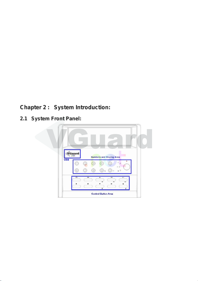
System’s front panel includes ‘Numbers and Display control Area’, and
‘Control Button area’. All button arrangements as above. This is mainly used
to operate the main system. The functions are as followed:
USB
Press once for the panel to open. There is USB application for file
download or firmware update.
Number 1-8 Buttons
When the number button is press under recording mode, the number of
9
camera displayed will be according to the number of button pressed.
Under 16 channels model, to select the enlarge images for camera 9-16,
you will require to use the split window button (number 9), and switch to
the split window images for camera 9-16, When under setting mode, the
number button is for setting of number 1-8.
Number 9 Button
When this button is press under recording mode, depends on the
different model, camera display window will be 4 split windows
(VGN4C-), Eight Split windows (VGN8C -) and 16 split windows
(VGN16C-). When under setting, this button is for setting the number 9.
Number 0 Button
When this button is press under recording mode, the display images will
be: Auto Scan for a single image, or 4 split windows or 8 split wind ows in
different pages. Camera numbers depends on the pages.
Power Indicator(
)
When power is on, this indicator will shown as green.
Recording Indicator(
)
When system is under recording mode, this indicator will be shown as
red.
Playback Indicator(
)
When system is under playback mode, this indicator will be shown as
yellow.
Record/ Switch to Recording Display Button:
1. When system not under recording status, press of this button will
activate recording function immediately.
2. When both recording and playback is functioning: Switching back to
the recording images. Detail information will be described later on.
Note: System’s defaulted is activating recording. You will require to
setup “Stop Recording” under system setup to stop recordin g.
Setting / List Button
1. Under system setting: Enter System setting, Save setting.
2. Under playback Operation: Enter Date list mode for playback
3. When activate PIP sub-window: Entering the adjustment of PIP
10
sub-window location, Save PIP sub-window location.
Leftward Button / Playback Backward
1. Under normal operation: Move selection leftward, Go to last page.
2. Under playback operation: For playback backward. Each backward
160 frames
3. When adjusting PIP sub-window: Move the PIP sub-window to the left.
Upward button / Step Playback / Pause Playback
1. Under normal operation: Move selection upward
2. Under playback operation: For step by step playback. Playback of 1
frame then pause playback.
3. When adjusting PIP sub-window: Move the PIP sub-window to the up.
Rightward Button / Playback Forward / Output Control
1. Under normal operation: Move selection rightward, Go to next page.
2. Under playback operation: For playback forward. Each forward 160
frames
3. When adjusting PIP sub-window: Move the PIP sub-window to the
right.
4. Not under playback or setting mode: Active output control button. This
will display relay output status, also can stop playing alarm sound.
Detail information will be described later on.
Select / Backup Button
1. Under normal operation: This is for selection and confirm button to
select and confirm the correct setting.
2. Not under playback or setting mode: To activate backup file button.
Backup the files from system hard disk to USB disk/device, by using
the playback software VG Player (V5.4 or above) for playback of the
file from normal PC. Detail information will be described later on.
Playback Button
1. Under normal operation: To activate playback function. Selection of
the playback files for playback. Detail information will be described
later on.
2. When both recording and playback is functioning: Switching back to
the playback images. Detail information will be described later on.
11
Subtract 1 / Next / Slow Speed Playback
1. Under normal operation: Subtract 1 when setting numbers or next one
selection button.
2. Under playback mode: Playback speed will be changes each time you
press the button to 1/2 1/4 1/6 1/8 slow speed playback
Downward Button / PIP Function
1. Under normal operation: Move selection downward
2. When both recording and playback is functioning: to activate PIP
functions; To display both recording and playback images we call it PIP
function. PIP sub-window’s location can be altered. Detail information
will be described later on.
Note: PIP function can only be done when connecting VGA output to
VGA monitor. TV output to TV Monitor will not display this
function.
Add 1 / Last One / Fast Speed Forward
1. Under normal operation: Add 1 when setting numbers or last one
selection button
2. Under playback mode: Playback speed will be changes each time you
press the button to 2 4 6 8 fast speed playback
Cancel / Stop / Alarm Log Button
1. Under normal operation: To cancel setting
2. Under playback mode: To stop image playback.
3. Not under playback or setting mode: To view alarm log. Detail
information will be described later on.
Note: This button is not the stop recording button. Press of this
button cannot stop recording. You will have to select the stop
recording function from system setting.
12
2.2 System Back Panel:
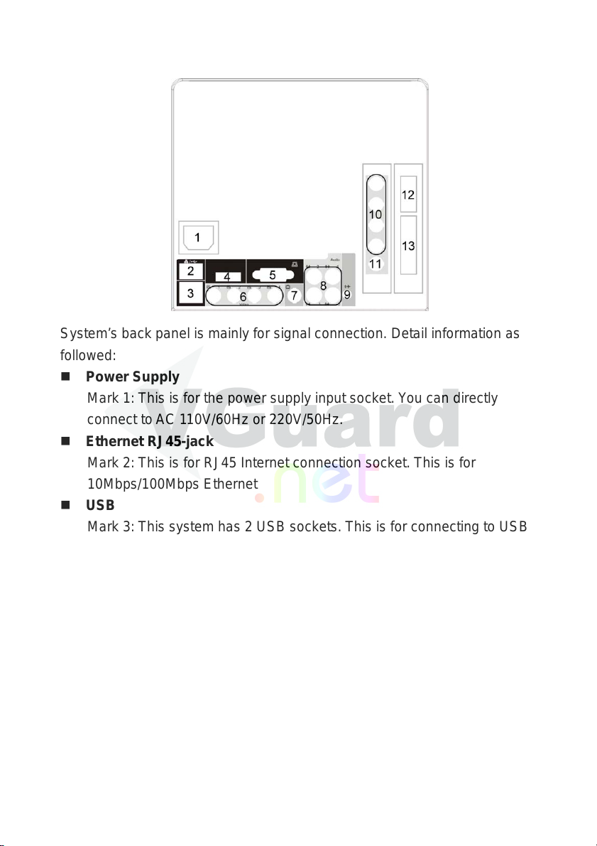
System’s back panel is mainly for signal connection. Det ail information as
followed:
Power Supply
Mark 1: This is for the power supply input socket. You can directly
connect to AC 110V/60Hz or 220V/50Hz.
Ethernet RJ45-jack
Mark 2: This is for RJ45 Internet connection socket. This is for
10Mbps/100Mbps Ethernet
USB
Mark 3: This system has 2 USB sockets. This is for connecting to USB
devices for backup images or update firmware.
Power
Mark 4: Power on/off. To turn on/off the system power.
VGA Output
Mark 5: VGA Output to connect to VGA monitor.
Video Input BNC-jacks
In RT4 System, Mark 6: Video Input 1-4 (From lef t to right); Mark 10:
Video Input 5-8 (From top to bottom).
In HRT4 System, Mark 6: Video Input 1-4 (From left to right); Mark 10
for 3 sets Video Input 5-16 (From top to bottom). Set order as red,
white black and yellow .
In SRT4 System, Mark 6 for 4 sets V ideo Input 1-16 (From right to left).
13
Set order as yellow, black, white and red.
TV Monitor Output BNC-jack
Mark 7: TV output BNC-jack to connect to TV monitor.
Audio Input RCA-jack
In RT4 System, Mark 8: Audio Input 1-4; Mark 11: Audio Input 5-8. Set
order as red, white black and yellow.
In HRT4 System, Mark 8: Audio Input 1-4; Mark 11: Audio Inputs
corresponded to camera 9-12. Set order as red, white black and yellow.
In SRT4 System, Mark 8 for 4 sets Video Inputs (order according to
numbers displayed). Set order as yellow, black, white and red.
Audio Output Earphone-jack
Mark 9: Audio out jack for live audio monitoring, or audio output when
playback saved files with audio.
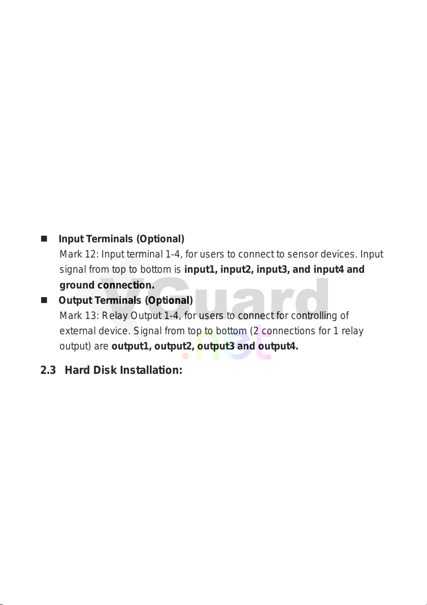
Input Terminals (Optional)
Mark 12: Input terminal 1-4, for users to connect to sensor devices. Input
signal from top to bottom is input1, input2, input3, and input4 and
ground connection.
Output Terminals (Optional)
Mark 13: Relay Output 1-4, for users to connect for controlling of
external device. Signal from top to bottom (2 connections for 1 relay
output) are output1, output2, output3 and output4.
2.3 Hard Disk Installation:
Please take extra notice that the system does not include a hard disk. So
before you start operating this system, it is suggested you install a hard disk
for recording files. VGuard N system has an IDE interface. It can connect 2
IDE hard disk,The setting for the first hard disk is Master and the second as
Slave.
Note1: This system is using Linux EXT3 hard disk format. It is
suggested to use the un-partitioned and un-formatted hard disk,
or use the already formatted to Linux EXT3 format hard disk.
Note2: There is no restriction size for a single hard disk capacity.
However, the maximum partition size will be 250GB.
Note3: After a brand new hard disk is installed, this system will
automatically partition and format this hard disk. When a hard
14

disk is over 250GB, system will automatically separate it into 2
or more same partition sizes.
Chapter 3 : System Setting
This is used to setup the system for operation needs. This system i ncludes
functions like, motion detection, alarm functions, security functions, Internet
functions and I/O control etc. Users can setup the system to suit your needs.
Detail information as below:
3.1 Setup Main Menu
SETUP 8102 060510 RT4
1.TIME/DISPLAY
2.CAMERA
3.ALARM
4.SYSTEM
5.NETWORK
6.I/O
7.PROGRAM
8.ADVANCE…
The first line shown on the main menu: First set of number means the
firmware version of this system. Second set of numbers mean the last
update date of this firmware. The third set is the system model. System
model: RT4, HRT4, SRT4.08 or SRT4.16. Ex...”XXXXX 070130 SRT4.16”
th
means this system is VGN16C-SRT4 last update on 30
15
Jan 2007.
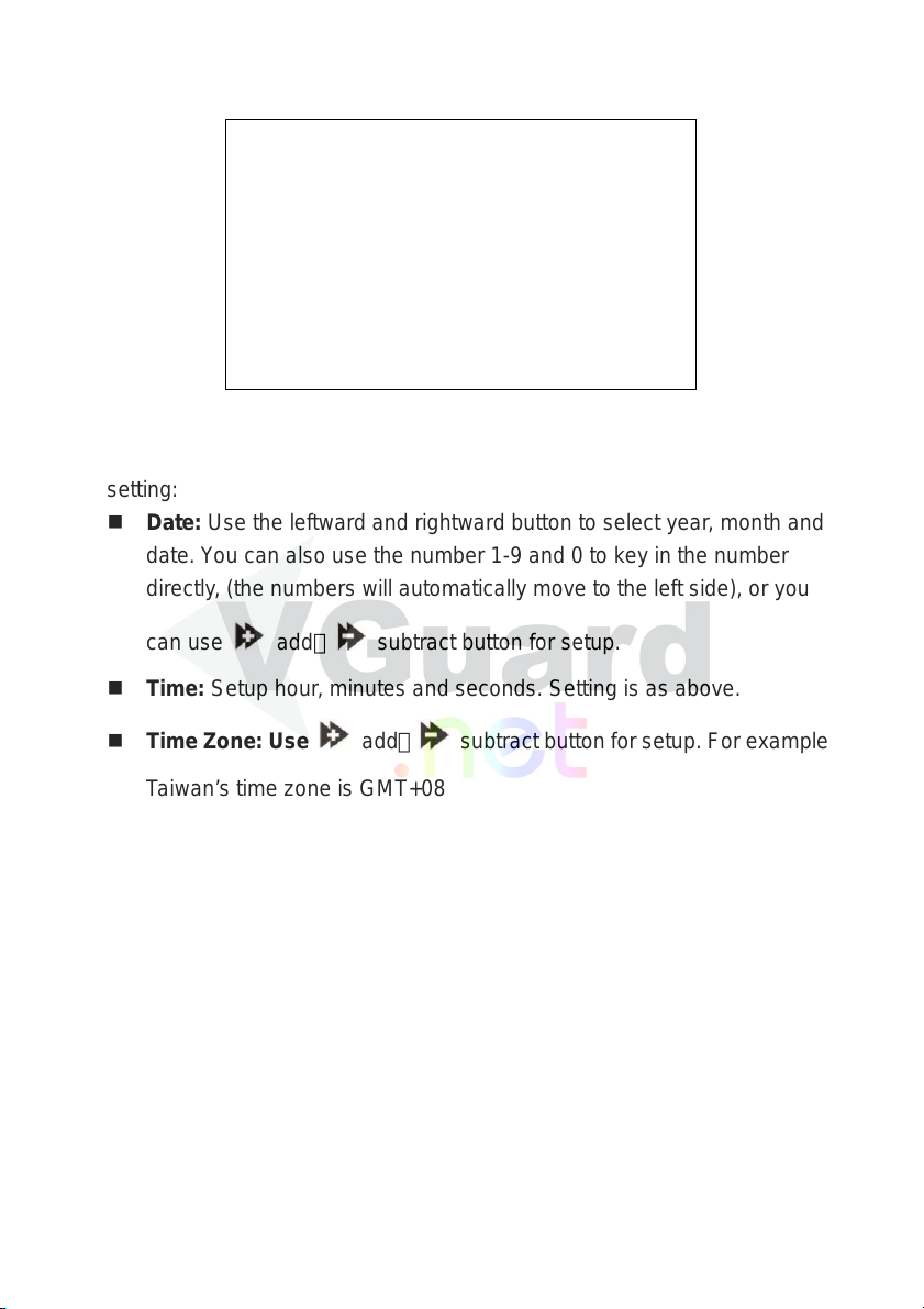
3.2 Time / Display Setup
TIME/DISPLAY SETUP
1.DATE 2006/5/8
2.TIME 18:00:08
3.TIME ZONE GMT+08
4.SYSTEM TIME ON
5.CAMERA NAME ON
6.SYSTEM STATUS ON
7.MAIN+SUB DISPLAY OFF
Time / Display setup is for setting the system time and display status. User
the up and down button to select and press the select button to confirm
setting:
Date: Use the leftward and rightward button to select year, month and
date. You can also use the number 1-9 and 0 to key in the number
directly, (the numbers will automatically move to the left side), or you
can use
Time: Setup hour, minutes and seconds. Setting is as above.
Time Zone: Use
Taiwan’s time zone is GMT+08
System Time: The defaulted is on (activate), system will display the
system time on the monitor.
Camera Name: Defaulted is on (activate), system will display the
camera name on the monitor. Camera name will need to setup under
“Camera Setup menu”.
System Status: Defaulted is on (activate), system will display
system status on the monitor. Mainly is showing the hard disk sizes
and hard disk free spaces.
Note: You must stop recording when setting up date, time and time
zone.
MAIN+SUB DISPLAY:Defaulted is “OFF”. Select a camera after
add、 subtract button for setup.
add、 subtract button for setup. For example
16
changing to “On”, or when enlarge one of the camera, this camera will
not be enlarge as full screen, instead it will be shown as main screen
and other camera images will be shown around the main screen in
smaller screen.
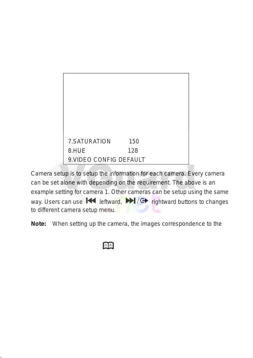
3.3 Camera Setup
CAMERA SETUP : CAMERA1
1.CAMERA NAME CH1--------
2.ENABLE ON
3.AUDIO ON
4.DISPLAY ON
5.BRIGHTNESS 115
6.CONTRAST 130
7.SATURATION 150
8.HUE 128
9.VIDEO CONFIG DEFA U LT
Camera setup is to setup the information for each camera. Every camera
can be set alone with depending on the requirement. The above is an
example setting for camera 1. Other cameras can be setup using the same
way . Users can use
to different camera setup menu.
leftward, rightward buttons to changes
Note: When setting up the camera, the images correspondence to the
camera will be displayed as full sizes for adjusting brightness, contrast,
saturation and hue. Press
Camera Name: You can only setup the camera name using English
or alphabet. You can use the number button directly for setting or use
add or substrate for setting.
Enable: Defaulted is on (activate), if the camera does not connect to
a camera, user can disable (OFF) this selection, and then this will not
be record.
Audio: Defaulted is on (activate). Audio functions uses 24kbps
ADPCM format for recording. File sizes are approximate 10MB per
to save the setting.
17
channel per hour.
Display: Defaulted is on (activate), you can change to off if display not
require.
Brightness: Brightness adjustment. Defaulted is 115, adjusting range
from 0-255, 0 is the darkest and 255 is the brightness.
Contrast: Contrast adjustment. Defaulted is 130, setting range from
0-225, 0 is the lowest and 255 is the highest.
Saturation: saturation adjustment. Defaulted is 150, setting range
from 0-225, 0 is the lowest and 255 is the highest.
Hue: Hue adjustment. Defaulted is 128, setting range from 0-255.
Video Configuration Default: When users want to get back to the
defaulted brightness, contrast, saturation and hue, press the
select / confirm button and press to save the setting.
3.4 Alarm Setup
This system supports alarm functions, which include sensor input trigger
alarm, video lost trigger alarm, and motion image trigger alarm.
Alarm setup is to setup the alarm function for each camera. Every camera
has its own setting. Below is the setup menu for the camera 1, other
cameras can be setup using the same method. Users can use
leftward、
18
rightward to change to different camera setup menu.
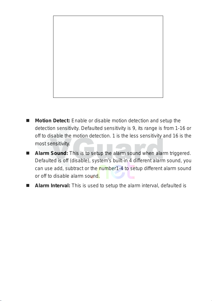
ALARM SETUP : CAMERA1
1.VIDEO LOST CHECK ON
2.MOTION DETECT 9
3.ALARM SOUND OFF
4.ALARM INTERVAL 120
5.MASK1 00 00:00 00
6.MASK2 00 00:00 00
7.MASK3 00 00:00 00
8.MASK4 00 00:00 00
9.OUTPUT TRIGGER -- -- -- --
Video Lost Check: Checking video lost. Defaulted is on (activate) so
when video lost, system will trigger alarm.
Motion Detect: Enable or disable motion detection and setup the
detection sensitivity. Defaulted sensitivity is 9, its range is from 1-16 or
off to disable the motion detection. 1 is the less sensitivity and 16 is the
most sensitivity.
Alarm Sound: This is to setup the alarm sound when alarm triggered.
Defaulted is off (disable), system’s built-in 4 dif f erent alarm sound, you
can use add, subtract or the number1-4 to setup different alarm sound
or off to disable alarm sound.
Alarm Interval: This is used to setup the alarm interval, defaulted is
120seconds, setting range from 100-999seconds.
Mask 1-4: You can setup maximum of 4 detection areas for each
camera. Each images is seen as 22 x 15 (NTSC) or 22 x 18
(PAL),so you can set a maximum of 4 area in(00 00)~(22 15)
(NTSC) or(00 00)~(22 18)(PAL). (00 00)is the top left hand
side and NTSC(22 15)/PAL(22 18)is the right bottom side. When
there is motion in the masked area, it will trigger alarm. When alarm
triggered, it will be save in the alarm log. User can playback the alarm
files from the alarm log.
Output Trigger: When alarm triggered, it can be set to control the
external alarm device form the output terminals. There are a total of 4
19
relay output control terminals for selection. This output control
terminals is optional.
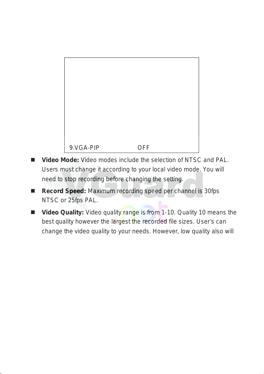
3.5 System Setup
SYSTEM SETUP
1.VIDEO MODE NTSC
2.RECORD SPEED 30
3.VIDEO QUALITY 10
4.SCAN TYPE QUAD DISPLAY
5.SCAN INTERVAL 3
6.AUTO RECORD ON
7.LIVE AUDIO ON
8.ALARM RECORD OFF
9.VGA-PIP OFF
Video Mode: Video modes include the selection of NTSC and PAL.
Users must change it according to your local video mode. You will
need to stop recording before changing the setting.
Record Speed: Maximum recording speed per channel is 30fps
NTSC or 25fps PAL.
Video Quality: Video quality range is from 1-10. Quality 10 means the
best quality however the largest the recorded file sizes. User’s can
change the video quality to your needs. However, low quality also will
influence the playback quality.
Scan Type: This is to setup the auto scan type. FULL DISPLAY
(single camera full screen display, recycling for every channels), or
QUAD DISPLAY (4 split window /2 pages display,), or Eighth Display
(as 9 split windows and 4 pages display)
Scan Interval: This is to setup up the interval for auto scan. Defaulted
is 3 seconds. Maximum interval time is 99 seconds.
Auto Record: When auto record is set at ON (activate), when
system reboot, system will automatically start recording. If this setting
is OFF (disable), then user will need to press the record button
manually for the system to start recording.
20
 Loading...