


\
r
I
E
r
=
\
u
$
tr
trE
trs
tri
jI
Ut
utI
Welcome!
Thank
you
for
buying Vgatescan
OBDII
Diagnostic
Scanner!
The
Vgatescan
OBDII
Diagnostic
Scanner
allows
you
to
access
your
OBDII
vehicle's data.
Vehicle
data, which
was only
available to
dealership technicians
using
expensive
proprietary
scan tools,
is now available
to every
people
who has
a Vgatescan!
Vgatescan is the
prime
choice
for users
keen on DlY.
a
Scanners support 13
protocols
and
you
can use two modes
to
scan which includes
Auto
scan mode and Manually scan
mode;
a
Vgatescan
tool can
support from
model
Sl
to modelS
9;
a
.More
than Tl
vehicle
manufacturer
built-in for
you.
O
DTCs
include
Generic
(P0,
P2, P3,
B0, U0
and
C0) &
manufacturer
specific
(P1,
P3,
BL,9.2,
Ul and CL,Cz,l
codes.
O
80
percent
trouble codes
have help
information in scan tool.
o
Scan tool has Black
Mask
OLED.
You
can
read the content of
scanner smoothly
when in strong
light.
O
DTC
definitions
are written in
user friendly
words
rather
than obscure technical terms.
t1I

-
Read
Diagnostic Trouble Codes
(DTCs)
-
Clear trouble
codes
-
Vieiv
real-time vehicle operation data
(Data
stream)
-
View Freeze
Frame data
-
View l/M
readiness
-Read
02 Monitor
Test
data
-Read
On-Board
Mon. Test
-Component
Test
-View
the
vehicle's information
The Vgatescan OBDII Diagnostic
Scanner
is
the
perfect
scan
tool to make
you
diagnose
a
problem
more easily!
Table of
Contents
tzt
t3I
5.4
Freeze
Frame
...'..'..'..45
5.5:/M
Readiness
..,.-......47
5.6
O2'Monitor
Test.....
...............'.'....49
5.7
On-Board
Mon. Test
...........
..'......51
5.10
Modules
Present....
.................'..57
5.11
Unit of
Measure
'.....58
5.12
State
Emission.....
.......'.......'......'59
5.Appendix
..........60
Appendix
1-PlD
List....
.......'........'.'.'...60
Appendix
2 ln-use
Performance
Tracking
Data
.'...".......'.."'...69
Appendix
3
l/M Readiness
1ist..............
..........,..74
Appendix
4
Vehicle Manufacturer........'......
....,.75
Appendix
5 Special
abbreviation
of Vgatescan.....'.....'.....
.... -
-.78
7. Warranty
and
Service
.....'...79
7.1
Limited
One Year
Warranty
.--......79
7.2
Service
Procedures
.........'..'.........80
1.
Safety
Precautions
and Warnings
For
your
Health and Safety,
please
read this manual
thoroughly
before
using
your
Scan
Tool. First,
you
should read
the
safety
precautions
and warnings. Safefy messages are
provided
to help
prevent personal
injury
and equipment damage.
EwAANTNGI
l-^l
twl
o
Do not drop or shock the scan tool.
o
Overpressure
can
cause
damage on liquid crystal
display
(LCD),
and it can also
provoke
malfunction
because of
its
own
feafures.
a
Do not connect or disconnect any test equipment with
ignition
on or engine running
a
Operate the vehicle in a well-ventilated work area; exhaust
gases
are
poisonous
o
Users should not remodel
or
take
the
product
apart by
themselves.
a
Do not
use fuel
injector
cleaning solvents when
performing
diagnostic
testing
o
Do not
place
tools or test equipment
on
fenders
or other
places
in engine compartment
o
Use the scan tool only as described in the
user's
manual
o
Follow
service
manual
warnings when working
around air
bag
components
or wiring
o
Do not
leave
a running
engine unattended.
o
Keep code reader dry, clean and free from
oil, water and
grease.
Use a mild detergent
on a clean cloth to
clean
the
tst
t4l
outside of
the tool.
o
Engine
systems that
malfunction can cause
injrrry
Acnurou
this
manual cannot
cover all
possible
conditions
and situations
that
may occur.
lt must be
understood
that
common sense and
caution are
factors
which
cannot
be built
into this
product,
but
must be applied
by the operator.
2.
General lnformation
2.1
About On-Board Diagnostics
(OBD)
ll
What
is OBD ll?
On-board
diagnostics version II
(OBD
II) is
a system that
the
Society of Automotive
Engineers
(SAE)
developed
to
standardize
automotive
electronic
diagnosis. Beginning in
1996,
most
new vehicles
sold
in
the
United States
were fully
OBD II
compliant.
The
OBD II
system
is
designed to monitor
emission control
systems
and key
engine components
by
performing
either
continuous
or
periodic
tests
of specifi-c
components
and vehicle
conditions.
When a
problem
is
detected, the
OBD II system
turns
on a warning
lamp
(MIL)
on
the
vehicle instrument panel
to alert
the
driver typically
by the
phrase
of
"Check
Engine"
or
"Seryice
Engine
Soon". The
system will also
store important information
about
the detected malfunctioll
so that a technician
can accurately
find and fix the problem.
Here
below follow
three
pieces
of such
valuable information:
1)
Whether the Malfunction
Indicator
Light
(MIL)
is
commanded
ON or OFF;
2)
\Mhich,
if
any, Diagnostic
Trouble
Codes
@TCs)
are
stored;
3)
Readiness
Monitor
status.
Does
My
Car
Have
OBD-ll?
171
t6I
All
cars
and light
trucks
built
and sold in the United States
after January
1,1996 were
required to be OBD
II
equipped.
In
general,
this
means all1996 model
year
cars and light
trucks are
compliant,
even
if
built
in late 1995.
Two
factors will
show
if
your
vehicle
is definitely OBD
II
equipped:
1) There will be
an
OBD
II
connector.
2) There will be
a note
on
a
sticker
or
nameplate under the
hood:
"OBD
II compliant".
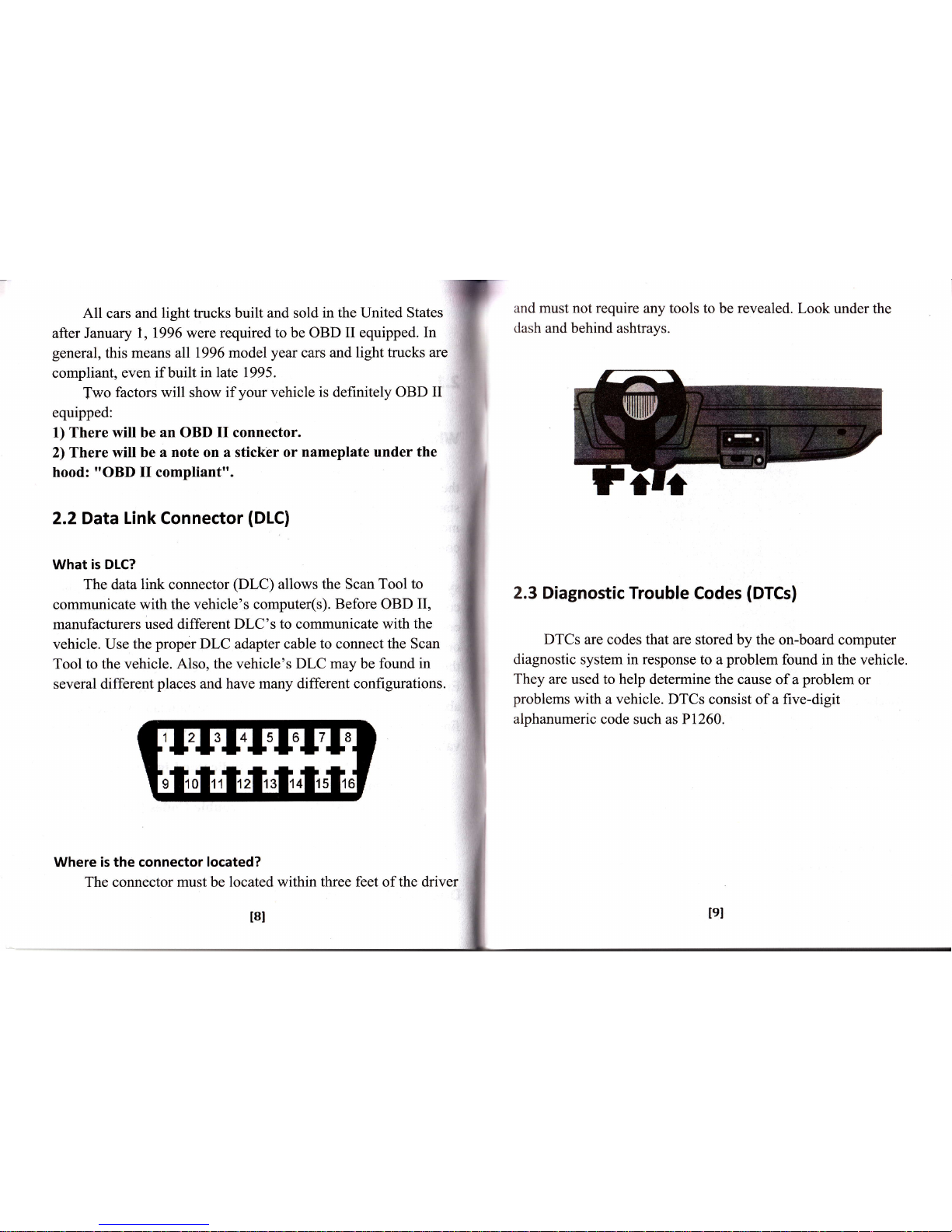
2.2Data Link Connector
(DLC)
What is DLC?
The data
link
connector
(DLC)
allows the Scan
Tool to
communicate
with
the vehicle's
computer(s). Before OBD
II,
manufacturers
used different DLC's
to
communicate
with the
vehicle. Use
the
proper
DLC adapter cable
to
connect
the Scan
Tool to the vehicle.
Also,
the vehicle's
DLC
may
be
found in
several
different
places
and have many
different configurations.
14213
I4l5I6I7I8
I
110111112I13I14
'!6
Where is
the
connector located?
The connector must be located within three feet of the driver
and must not require any tools
to be revealed. Look
under the
dash and
behind ashtrays.
2.3 Diagnostic Trouble
Codes
(DTCs)
DTCs
are
codes that
are stored by the on-board
computer
diagnostic system in response
to a
problem
found in the vehicle.
They
are used to help determine
the cause of a
problem
or
problems
with a vehicle. DTCs
consist of a five-digit
alphanumeric
code
such
as PI260.
I9I
t8t
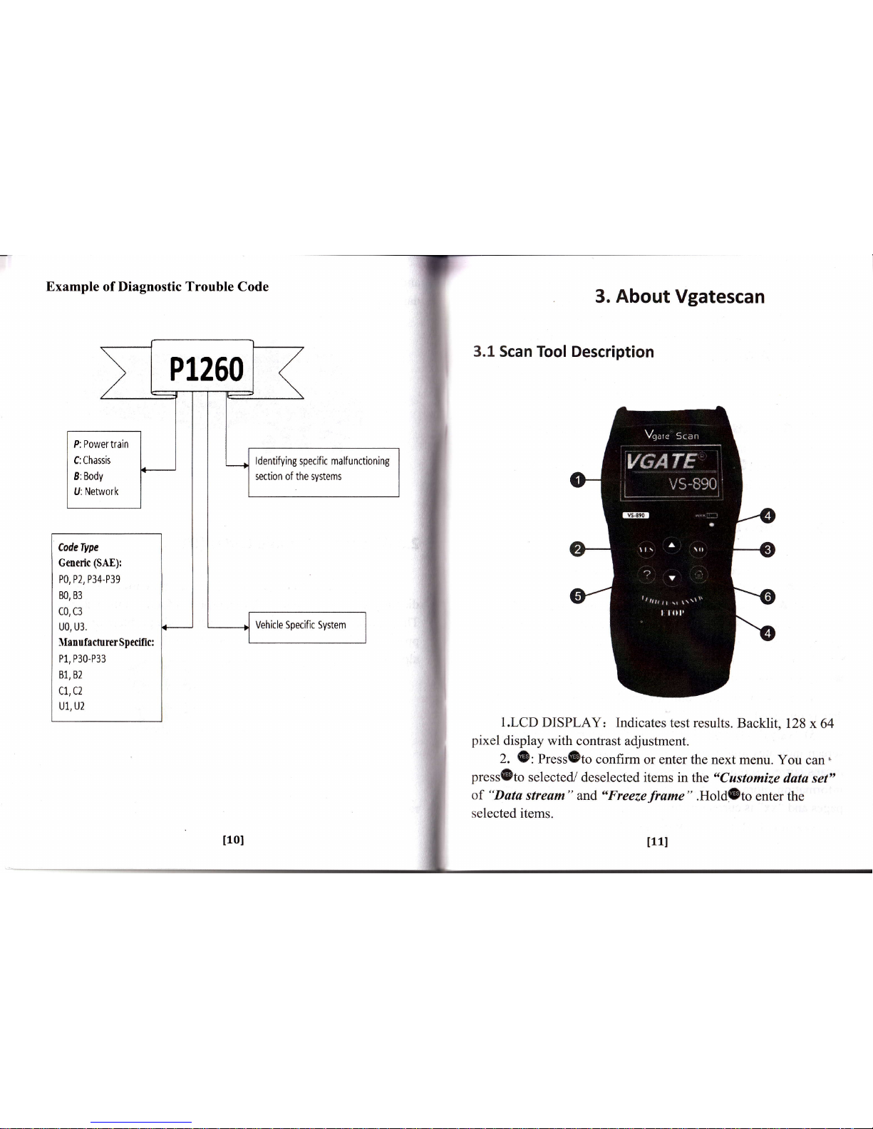
Example
of
Diagnostic Trouble
Code
3,
About
Vgatescan
3.1 Scan Tool Description
1.LCD
DISPLAY: Indicates
test results.
Backlit,
128
x 64
pixel
display with
contrast
adjustment.
2.
(E:
Press(Dto
confirm or enter the
next menu.
You
can.
press(Eto
selected/
deselected
items
in
the
"Customize
data set"
of
"Data
stream"
and,
"Freezeframe"
.Hold@to
enter
the
selected items.
P1260
P: Power train
C:Chassis
8: Body
U: Network
ldentifying
specific malf unctioning
section of the systems
CodeType
Generic
(SAE):
P0, P2,
P34-P39
80, 83
CO, C3
u0,
u3,
llan ufecturer Spcific:
P1, P30-P33
81, 82
cL,c2
Ul, U2
Vehicle Specific System
IlOI
t11l
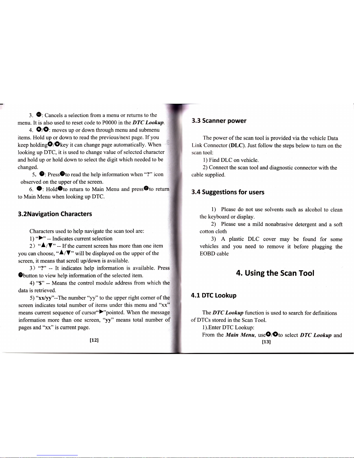
3.
@:
Cancels
a selection
from a menu or returns
to the
menu. It
is also used to reset code
to P0000 in the DTC Lookup.
+.
OtO:
moves up or down
through
menu
and submenu
items. Hold up or down
to read the
previous/next
page.
If
you
keep holdingOlOtey
it
can change
page automatically. When
looking
up
DTC, it is used to change value
of selected character
and
hold up or
hold
down
to select the digit
which needed to be
changed.
5.
9:
Pressgto
read the help
information when
o'?"
icon
observed
on the
upper of the screen.
6.
O:
Hold3to return
to Main Menu
and
pressOto retu
to
Main Menu when looking up
DTC.
3.2Navigation Characters
Characters
used to help navigate
the
scan
tool are:
l)
">"
--
Indicates current selection
2>
*
Llf
"
--
If the
current
screen
has more
than
one
item
you
can
choose,
etllf
n
wil
be displayed
on
the upper of
the
screen,
it means that
scroll
up/down
is available.
3)
"?" --
It indicates help
information
is available.
Press
ebutton
to view help information
of the selected
item.
4) "$"
--
Means the control
module address
from which the
data
is retrieved.
5)
"xx/yy"--The number
"yy" to the
upper
right
corner
of the
screen
indicates total number of
items under this menu
and
"xx"
means current sequence of cursor")"pointed.
When
the message
information
more
than
one screen,
"yy" means
total number of
pages and
"xx"
is
current
page.
3.3 Scanner
power
The power
of
the
scan tool is
provided
via the vehicle
Data
Link Connector
(DLC).
Just follow the
steps below to turn
on the
scan tool:
l) Find DLC
on vehicle.
2) Connect
the scan
tool and diagnostic
connector
with the
cable
supplied.
3.4
Suggestions
for users
l) Please
do
not
use solvents
such
as
alcohol
to
clean
the keyboard
or display.
2)
Please
use a mild
nonabrasive
detergent and
a soft
cotton cloth
3) A
plastic
DLC
cover may
be
found
for
some
vehicles
and
you
need to
remove it
before
plugging
the
EOBD
cable
4. Using
the
Scan Tool
4.1 DTC Lookup
The DTC
Lookup
function is
used to
search for
definitions
of DTCs
stored
in the
Scan Tool.
1).Enter
DTC Lookup:
From
the Main
Menu,
useO/Oto
select DTC
Loohup
and
I13I
1L2l
press@to
enter.
2).From
DTC Lookup
menu,hold
OIO
to move to the
clesired
character,
press
Ol0
button
to change
selected
character
and
press
{B
button to confitm.
If
you
want to change
the code
to P0000,
you
can
press
@
key to clear the
code.
3)
Before
you
read the
DTC
dcfinition,
you
must select
the
vehicle
manufacturer"
usc thc
OIO
scroll
buttons
to sclect
the
vehicle
manufacturcr
and hold
OzO
to
view
previous
or
next
screen.
You can also
kccp holding
Oloto
automatically
scroll
up
and down.
Then
prcss
@
to view the
DTC definition.
4) View the DTC definition on screen.
When the DTC's
tlcflrnition
covers more than
one screen,
press OIO
to view
rrtlditional
information on
previous/next
screens.
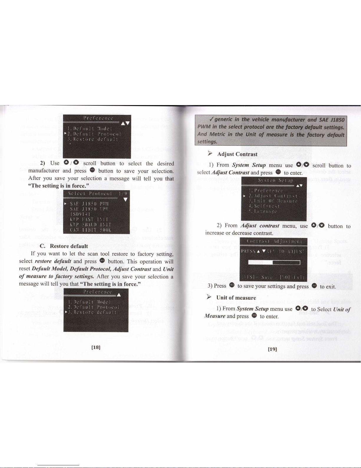
4.2
System Setup
The
scanner
allows
you
to make the following settings:
oPreference:
When the scanner is auto scanning, thc scurr
tool
will first try the default
protocol
which
you
havc
sct.
'l'[ris
114l
5 ) Press
@t.y
to return to Muin Menu.
llsI

will save
your
time from scanning
each
protocol
every time
you
connect
your
device to
your
vehicle.
And after
you
selected the
default
manufacturer,
the
cursor
points
to
the
default
manufacturer unless
you pressOlO key to change.
oAdjust
Contrast:
Adjusts the contrast
of the LCD
display
oUnit
of
measure: You can set
the
unit
of
measure to
imperial or
Metric.
oSelf-test:
You
can check
the
scanner's
display
and
keyboard that if they
are working
normally.
olanguage:
You can select different
languages
in this
mode.
To enter
the
Setap
menu mode:
From Main
Menuuse
O/O
scroll
to select System
Setup
t
A.
Vehicle
manufacturer setup
l) From Preference
menu,
use
OIO
scroll
Defautt Model, andpress
(D
button.
2) Use
OrO
manufacturer and
press
you
save
your
selection
is in force."
scroll buffon to
G
button
to
save
a message
will tell
button
to
select
select
the
desired
your
selection. After
you
that
"The
setting
From System Setup
menu use
O
I
O
scroll
to
Preference, and
press
(D
to enter.
You can
make the manufacturer
and
protocol
settings.
B. Protocol setup
1) From
Preference menu, use
OIO
scroll
select Default
Protocol, and
press O
buuon.
select
lLTl
t16l
bqtton
to
2)
Use
O
I
O
scroll
button to
select the
desired
manufacturer
and
press
(B
button to
save
your
selecti
After
you
save
your
selection
a message
will tell
you
that
"The
setting is in
force."
C.
Restore
default
If
you
want
to let
the scan
tool restore
to factory
setting,
select
restore
default
and
press
@
button.
This
operation will
reset Default
Model,
Defoult
Protocol,
Adjust
Contrast
and Unit
of measare
to
factory
settings. After
you
save
your
selection
a
message
will tell
you
that
o'The
setting
is in force.,,
1) From
System
Setup menu
use
OtO
scroll
button
select
Adjust
Contrast
and
press
(E
to
enter.
2) From
Adjust
contrast
menu,
use
OrO
button
increase
or
decrease
contrast.
3) Press
@
to save
your
settings
and
press
0
to
exit.
1) From
System
Setup
menu
use
OIO
to
Select
ltnit
of
Measure
andpress
(E
to
enter.
l18l
tlel
2)
From Unit of Measure
menn, use
OIO
scroll button to
select
the desired unit of measurement.
The
Unit of
Measure
ig
used
in Data stream; Freeze
Frame and On-Board
Monitor
Test"
Self-test,and
press
(&
to
enter.
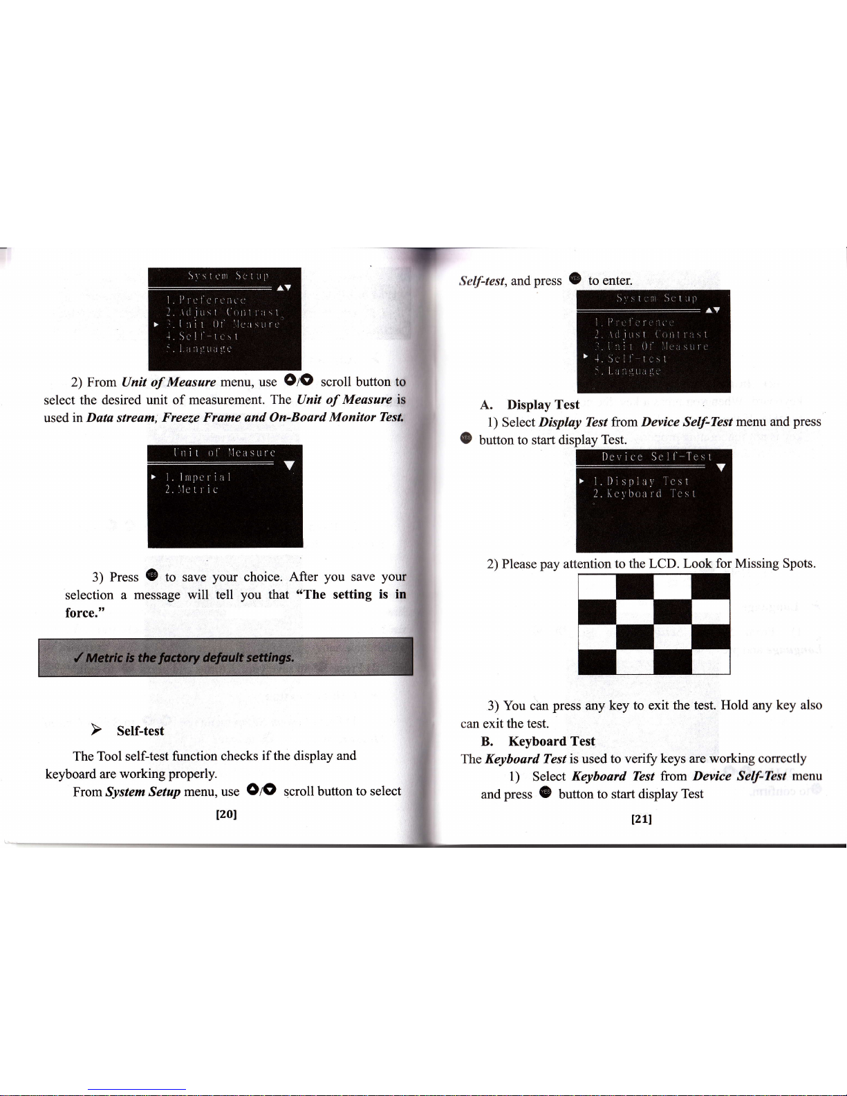
A. Display
Test
1)
Select
Display Tbst fuom
Device
Self-kst
menu and
press
button
to start
display Test.
2)
Please
pay
attention to
the LCD. Look for
Missing Spots.
3) You can
press
any
key to exit
the test. Hold any key also
can exit
the test.
B. Keyboard
Test
The Keyboard Test is used
to veriff keys are working
correctly
l) Select
Keyboard
Tbst from Device
Self-Test
menu
and
press G
button
to start display
Test
o
3) Press
(B
to
save
selection
a message
will
force."
your
choice.
After
you
save
your
tell
you
that
"The
setting
is in
The
Tool self-test function checks
if the
display
and
keyboard are
working
properly.
From System
Setup menu, use
OIO
scroll button
to select
1201
121l
T-
2)
In
this test you
can
press
any key to
check
thc
keyboard.
when you
press
a
key, the
corresponding
icon
will
twinkle.
If
the corresponding
icon
does not
twinkle,
then
the
key
is
not
functioning
properly.
3) After
your
selection,
it will return to system setup.
And
llrc
screen
will
display in the
selected
language.
4.3 Tool lnformation
The Tool Information
function allows
viewing
of some
irnportant
information
such
as serial
number
and software
version
rrrrmber
of the scanner.
1)
From Main menu, use
OIO
scroll button to select
Tool lnformation and
press
(B
to view.
to
Select
button
to select
different
Languages
and
press
::
View
tool
information
on screen.
Press
@
key to
return.
2)
3)
2)
Use
Olo
@to
confirm.
i:
?:
;
.i
$-
3)
Hold
@to
rerum.
l)
From
System
Languageandpress
@
Setup
menu
use
O
Z
O
to
enter.
Izzl
l23l

4.4 lnstalling
the USB Drivers & PC Update
I
)
Install:
-
Please connect
the Vgatescan USB cable to
your
and
then there will
be a dialog window
popped
up
titled
66
New Hardware Wizard".
Select
'6No,
not
this time" and then click
"Nexf'
button
continue:
Select
"Install
from a list or specific location
(Adv
and then
click
"Next"button
to
proceed:
Check
the
"Include
this location
in
the
search" checkbox
irnd
click
"BFohtse"
button. A
standard
o'Browse
for folder"
dialog
will
show up, and
you
need
to choose a specific folder
according
to
your
operating system.
When
select
specified file is
done, the file's name
will
be
displayed in the
browser
location
as follow
Choose a
proper
lblder and click
$OK"
to close the
dialog. Now there will
be
some text indicating the location
you
have
just
chosen
beneath
lhe
"lnclude
this location in the
search"
checkbox
as
shown in
the
following
picture.
Welcom6 to the Found l{*
Hadw3 Wizild
vl&dtd6ddl#tub
dqopd@,6e*e.l.&O,
d6
hWtu&w6*lssFlrMl
kglee
bv,fuffib\^/i*!&r'db
124l
125I

Compleling the
Found Nil
Ha,dwa,e Wizald
Ih
NqdhJ,n*d nnfuh.dr!.,.
rd
;/
use.s""c*""'
kFBhberh{ad
cid_-l
'
l:'lt:::
;iii,jy
:,
.
:r
..,,::*ts
-l{ryl
__cr.dJ,l
After
installation,
a balloon
wills
pop-up
on
the
bottom
of
Click
"Next"
button to start
installing
the driver.
When
install the software
is complete,
please
click
"tr{
button.
Now,
a dialog
named
'oCompleting
the
Found N
Hardware
Wizardl'
will show
up.
It means
the
wizard
finished
installing the software
for
USB
to serial
Comm.
Please click
"Flrisft"
button
to close
the wizard.
thc
screen as
shown in
the following picture.
The
Driver
installation
is
complete now!
2)
Setup
Right
click on the
"My
Computer',
from
desktop.
Select
"Manage"
and
click the left
mouse
button
to enter.
Click the
left
mouse
button
on the
"Device
Manger,,
from
Computer
Management,
and then
search
the specified port
which
l27l
126l

r
used to update.
Left click
"Device
Manger" and click
the
+
sign
on the left of the Port icon.
"Prolific
USB-to-Serial
Comm Portable
(COM7)'is
the
port
which used
to
update.
Please note: the setup of
this
port
must be same with the one
which used in PC update,
if
are different,
the PC update will
fail to connect to
your
device.
If the default
port
is
beyond
the one which
is
used
in PC
update,
you
need to setup
the
COM
number
manually
as
following:
Click
the right mouse
button on the
*Proliftc
USB
Comm
Portable
rcOM7 )
",
and
select
oProperties"
to
enter.
Select
uPort
Settings"
on the Prolific USB-to-Serial Comm
l)ortable
(
COMT )
Properties
as
follow,
and then click
the
"Advanced"
button to enter.
Select
the
port
from
COMI
to COM4 to be
port
used to update.
Please
note: this
port
must
be same
with the
update.
the
specified
one used
in PC
When
you
have
selected
a
port,
click
nOK"
button.
Now,
setup
is
completed!
l28l
lzel
i
.
nmccan.lrrgflooP
PC upoArt
-srr$nrq
I
u-r-,[6!
N,.lffi=
-
r-ii66nrr
r-;,
I
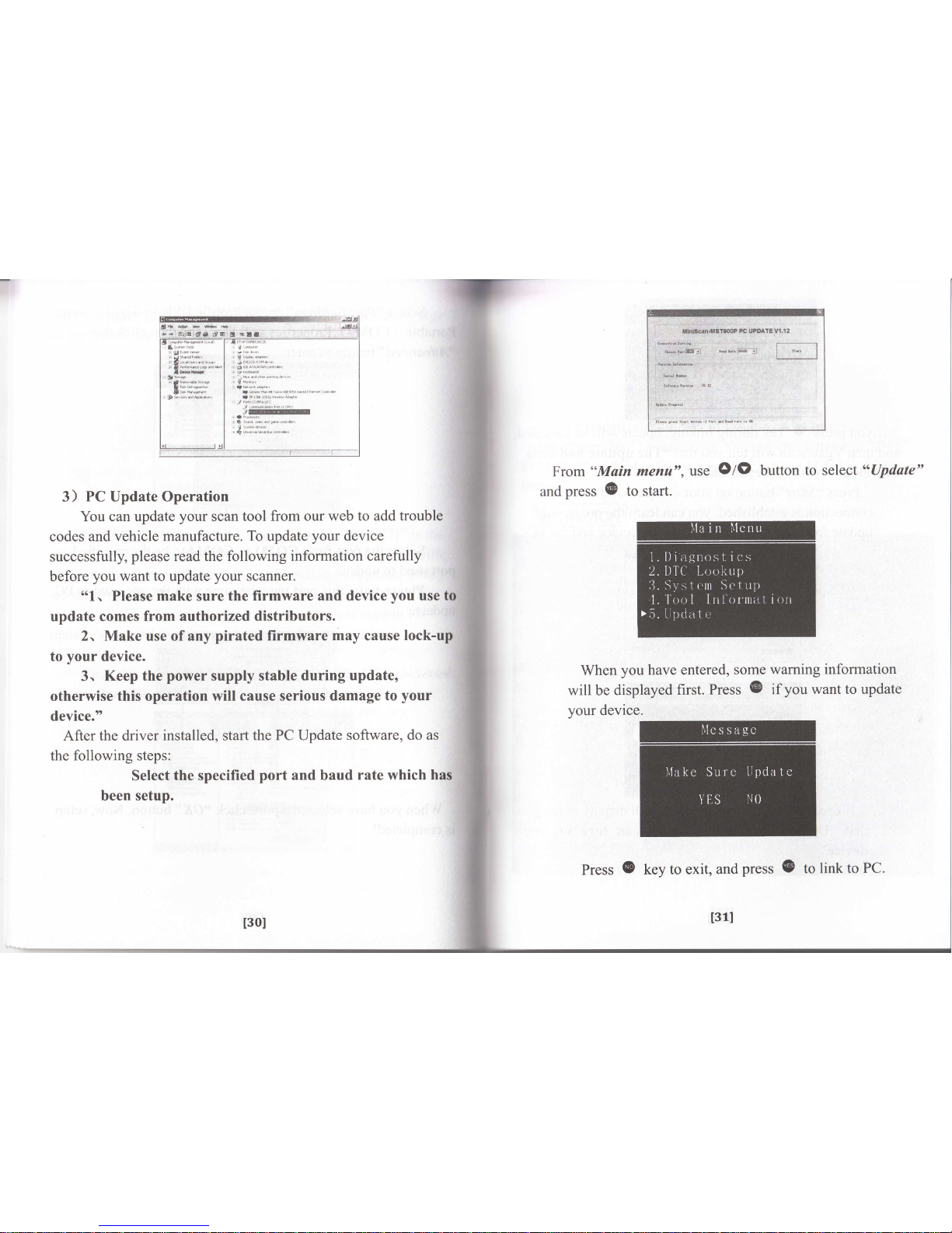
From
"Main
menu",
and
press @ to start.
use
O/O
button
to
select
"Opdate"
3) PC Update Operation
You can update
your
scan
tool from our web to add
trouble
codes
and vehicle manufacture.
To
update
your
device
successfully,
please
read the following
information carefully
before
you
want to update
your
scanner.
"1,
Please make sure
the firmware and device
you
use to
update
comes from authorized
distributors.
2. Make use of any
pirated
firmware
may
cause
lock-up
to
your
device.
3.
Keep the
power
supply
stable during update,
otherwise this operation
will cause serious damage
to
your
device."
After the driver
installed,
start
the PC Update
software, do as
the
following steps:
Select
the specified
port
and baud
rate
which
has
been setup.
When
you
have
will be
displayed
your
device.
entered,
some
warning
information
first.
Press
@
if
you
want to update
Press
@
key to exit,
and
press @ to
link to
PC.
t30l
t31l
If
you press
0
key
during
linking,
update
will
be ca
and then Vgatescan
will tell
you
that
"The
update had been
canceled. Press NO key to
back".
Press
"Srcrr"
button on
your
computer. After the
connection is
established,
you
can
learn
the
progress
of
update
from
the two
status bars
in the
device
and the
PC.
After
update, the number of trouble
codes or vehicle
manufacturers
will
be
increased.
You can check
these
in "DTC
LOADED" in Tool
information and
nYehicle
M.E" in DTC
lookup.
AcRunoru
If
update is
succeed. A message
will
display
that
"Update
Succeed!
Now
you
can turn
device"
to tell
132l
off
your
t33l

5. OBD
ll Diagnostics
From Main menu,
use
O
z
O
scroll button to select
Diagnostics and
press
@
to enter.
Before scan
protocol, you
should
select a scan
Vgatescan scan tool has two scan modes
which are
and Manually Select.
diagnosed.
protocol
and
press{B.
The
scan tool
will
links
to
the vehicle
with
the
protocol
you
have
selected.
If the
scan
tool
fails
to
communicate
with
the vehicle,s
ECU
(Engine
control
Unit)
,A
*Link
Error!"
message
shows
up on the
display.
You must
make
sure
the following
things:
D
The
vehicle
is OBD
compliant.
D
Tttrn
the key
ON with
engine
OFE
D
DLC
is
firmly
connected.
D
The
integrity
of diagnostic
wiring
harness.
If
the
summary
of system
status
(MIL
status,
Code found,
Monitors
NiA,
Monitors
Ready,
Monitors
Not
Ready)
show
up
on
mode. The
Auto
Scan
OBD ll
protocols
will
be observed on
the screen .When the
scan
tool links to the vehicle, the communication
protocol
is
automatically
detected, and is.used until
another vehicle is
l34I
tssl

the screen,
it
means
link succeed.
Press
{B
to enter
Diagnostic
menu and
press
@
key to
return the
Select Scan
Mode.
When
more than one
vehicle
control
module
is detected
by
the
scan tool,
you
must select
the
module
where
the data
may
bc
retrieved.
The
most often
to be selected
are
the
ENGINE
and AT.
The Diagnostic
menu
includes
the
following
modes:
C Read DTCs
D Clear
DTCs
D Data
stream
DFreeze
Frame
tIllNI
Readiness
D
02
Monitor
Test
O On-Board
Mon.
Test
O
Component
Test
C Vehicle
Information
D Modules
Present
D
Unit
of
Measure
D State Emission
5.1Read
DTCs
You can
read the trouble
codes
of
your
vehicle
in
this
mode.
It irrcludes All
DTCs,
Stored
DTCs and
Pending DTCs.
l) Use
OIO
scroll
button
to select
Read
DTCs
from
Diagnostic
Menu
and
press @ to enter.
2) Use
OIO
to select
All
DTCs,
Stored
DTCs or
Pending
DTCs
form
Select Operation
Press
(B
to enter.
3)
.View
DTC
List
After
selected
one
item
in
cnter
the DTC
List.
the
Select
Operation
yotr will
l37l
[36]

U
4)
View
DTCs
and
their
definitions
on
screen
You must
select vehicle
manufacturer
before
you
view the
definition
of
the DTC.
Press
6
to confirm.
lf the
manufacturer
for
your
vehicle is not
listed,
use
Ol$
to select
Other
and
press
S
button. Press
&
kev
to return.
vicw
additional information on
previous/next
screens.
5) View the help information
If an
"?"
icon
display on the upper of the screcn, it inclicatcs
tlrc code
you
selected
has help information. You
can
prcss
"O"
hutton
to
view
the help information
of
this DTC. Press'oO" again
()r
press S
to
return.
5.2 Clear DTCs
After
press &
in the
definition
of the DTC
will
manufacturer
is
displayed
v
e
hic
le m an
ufa ct urer
list the
display on
the screen
.The
vehicle
to
the upper
right
corner
of the
screen.
In
this
screen,
you
can hold
OZ$
to
view
previous/next
trouble
code's definition.
When
DTC'
definition
covers more
than
one screen,
"LIY"
will
bc displayed
on the
upper
of
thc
screen.
It means
that
scroll
up/down
is available, press
Ol{}
to
t38l
[3e]

l) Use
OzO
scroll
button
to select Clear
DTCs
diagnostics
menu
and
press
@
button.
from
2) A waming
message comes
up asking
for
confirmation.
Press
@
to continue
and
press
@
to retum
the diagnostics
il lctlu.
4)
The clearing
result
is
"Erose
Succeed!"
or
"Erose
Failed!"
A)
If the
codes
are cleared
successfully,
afl"Erase
Succeed!"
message shows
on
the display.
B) If
the
codes
are not
cleared,
then an
"Erase
Foiled!"
message appears.
5)
Press
(B
or
@
to
return
diagnostic
ntcrttr
I
I
your
If
you
do
not
want
to
clear
DTCs,
press
@
key to exit.
3) If
you
want to clear the
DTCs,
press
(B
and
then
another
message
comes up asking
for
your
second selection.
t41l
t40l

5.3 Data
stream
This
mode function
allows
viewing
of live
or real
time
data
of vehicle's
computer
module(s).
Dutu
stream
list
shows
all supported
PID
data for
the vehicle
being
tested.
1)
To view
live
data,
,se
SfS
button
to select
Data
stream
from
diagnostic
Menu ancl
press
@
to
enter.
2)
Please
wait
a moment
while
the
scan tool
reading
PID.
3)
The Dutu
stream list includes"Complete
Datu
Sef',
"Customize
Data
Sel"
and"Ilnit
of Measure".
A)
To
view
Complete
Dato
Set,use
Oltl
button
to
select
Complete Data
Set fromo'select
Datu,,
menu
and
press
@
to
enter.
View live PIDs
on
the
screen.
If the retrieved infbnnatiorr
t rvcrs
more than
one screen, use
Q/O
button,
as lleccssary,
rrrrtil
all
data have been shown up.
If an
"
?
"
icon
display
on the upper of the screen, it
rrrrlicates
the live data
item
you
selected
have help informatiorr
You
can
press
"0"
button
to view the help information o1'tlrrs
,llta.
The
help information
will show
the full namc of
livc
tLrll
votr selected.
/
The:
indicates
l42l

Press
"O"
again or
press
@
key to retum.
+
If it is not
support, a
message
will display.
B) View
Customize Data
To view
customize data,
use
Ol()
button
to select
Customize Duta
Set
from
Select
Data
and
press @
to enter.
After you
enter the customize set,
you
can
press
(E
to
select/deselect
data, and
press
OUO
to move
up/down list.
Selected
parameters
are marked
with solid squares.
Press
@
key
to
return.
C)
Unit
of
Measure:
Repeat
procedures
from
System
Setup
to
setup
the
unit
of
Measure.
5.4 Freeze
Frame
When
an emission-related
fault
occurs,
certain
vehiclc
.''t,rrclitions
arc recorded
by
the on-board
computcr.
This
rnlirrmation is
rcferred
to as
freeze
frame
data.
View
Freczc
l)ittlt
r\
a snapshot
of
the operating
conditions
at
the
timc
of
an
('rnission-related
fault.
1)
To
view
Freeze
Frame,
use
OIO
button
to
sclccl
Freeze
Frame
from
diagnostic
Menu
and
press
@
to ctttcr.
I
:
$
Please
wait
a moment
while
thc
scttrr
lttol
t'e irtlittl',
Then hold
(B
to confirm and read
data
you
have selected.

PID.
3)
The
Data
stream
"CustomiTe
Data
Set"
and
Iist
includes
"Complete
Data
Set,,,
"Unit
of
Measure"
If
an
o'?"
icon
display
on
the
upper
of
the
screen,
it
indicates
the
live
data
item
you
selected
have
herp
information.
you
can
press "(e"
button
to
view
the
help
information
of
this
data.
The
help
information
will
show
the
fuil
name
of
rive
data you
selected.
A)
To
view
Complete
Data
Set,
use
OfO
button
to
s_elect
Complete
Data
Set
from,,select
Dota,,
menu
and press
(B
to
enter.
press
(O
again or
@
key to
return.
B)
Customize
Datu
Set
and Unit of
Measure are
the
same
to the
Data stream.
Press
@
button
to retuffI
to diagnostic
Menu.
5.5 t/M
Readiness
The
l/M Readiness
(lnspection
/
Maintenance)
functton ts
used
to view
a snapshot
of the
operations
for the emission system
on OBD
II vehicles.
It
is an excellent
function.
To
guarantee
no
fault exist make
sure all monitors
are
OK
or N/A
and no DTC's
exist.
During
normal driving
conditions,
the
vehicle's computcr
scans
the emission
system.
After
a specific
amount of drivc
tirnc
(each
monitor
has
specific
driving
conditions and
timc
rcquircd),
the computer's
monitors decide
if the vehicles emission
systcttt is
working correctly
or
not
as
well as
detecting out of
rangc vitlttcs,
When the
monitor's status
is:
OReady--
lndicates
that a
particular
mclnitor bcirrg
1461 l47l

checked
has
completed
its
diagnostic
testing.
O
Not
Ready --
Indicates
that
a
particular
monitor
being
checked
has not
completed
its
diagnostic
testing.
O
N/A (Not
Applicable)
--
Vehicle
does
not
support
that
monitor.
l)
Use
OIO
button
to
select
I/M
Readiness
from
diagnostics
menu
and
press@
Our
scan
tool
support
two types
of I/M
Readirzess
tests:
O
Since
DTC
Cleared--indicates
status
of
the
monitors
since
the
DTCs
are
erased
O
This
Driving
Cycle--indicates
status
of
monitors
since
the
beginning
of the
current
drive
cycle
Use
OuO
to
select
Since
DTCs
Cleared
or
This
Driving
Cycle.lf
the
vehicle
supports
both
types
of
tests,
then
both
types
will
be
shown
on
the
screen
for
selection
press
@
to enter.
If
enter
Since
DTCs Cleared
or
vicw the information of
the emission
This
Driving Cycle.
You can
system on OBD
II vehicles.
If there
is an
"?
"
icon
on
the
upper
of the screen,
it
means
you
can
press
"0"
button
to
view the
full name .
Press
@
to return
to
diagnostic
menu.
5.6 02
Monitor Test
OBD
II regulations
require applicable
vehicles
monitor and
tcst oxygen
(O2)
sensors
to determine
problems
relatcd
to lircl
rrnd emissions.
The O2
Monitor
Test allows
retrieval of
completed 02
sensors
monitor
test results.
These tests
arc ntlt
on-demand
tests and
they are
done automatically
whcn cnginc
l4el
t4Bl

operating
conditions are
within
specified
limits. These
test
results
are saved in
the
on-board
computer's
memory.
l)
Use
OIO
button to
select
02 Monitor Test
from
diagnostic
menu
and
press
@
button.
A) If
your
vehicle
communicates
is not
zse controller
area
network
(CAN):
Use
OiO
button to
select item
from
O2 Sensor
Iest menu
and
press
(B
to
enter to view
information.
View
test results
of
selected
02 sensor.
B)
If the vehicle
communicates
using
a controllcr arca
network
(CAN),
02
monitor
tests are
not supported
by
vehicle.
A message displayed
on
the screen
will
tell
you
"According
to
[SO, this
function
is not supported
on CAN.
The same
function
is implemented
in 7.On-Board
Mon.
Test
l'or
CAN
bus".
[t means
for
02
Monitor
Test results of
CAN-equipped
vehicle,
see
chapter
"On-Board
Mon. Test".
So
you
can
press
@
to
enter On-Board
Mon,
Tesl or
press
(E
key
to return diagnostic
menu.
5.7 On-Board
Mon.
Test
The On-Board
Mon.Iesl
function
Use
OIO
button
icon
displays.
Press
(E
to
view
more
screens
of data
key
to return.
Is0]
if
"Llv"
tsu
is
useful
aftcr
servicing

or
after
erasing
a
vehicle's
memory.
Test
results
do
not
necessarily
indicate
a faulty
component
or system.
a
Non-CAN
vehicles
On-Board
Mon.
Test
receives
test
results
for
emission-related
powertrain
components
and
systems
that
are not
continuously
monitored.
'
cAN
vehicles
on-Board
Mon.
Test
receives
test
resurts
for
emission-related
powertrain
components
and
systems
that
are
and
are not
continuously
monitored.
l)
Use
OZO
to
selected
On-Board
Mon.
Test
from
diagnostic
menu
and
press
@
to
enter.
2)
From
On-Board
Mon.
Test
menu,
use
OIO
to
select
a
test
to
view
and
press@.
+
If it
is
not
a
CAN-vehicle,
test
selections
will
be
as
below:
Press @
to
view
the
information.
Press
"0"
key
rr'lccted.
to
view help
information
of
the item
you
+ For CAN-vehicles,
test
selections
will
be as
below:
Press
(B
to view the informatton:
+
If
the
vehicle
under
test
does
not support
thc
tttotlc. tt
ls2I
ts3l
mcssage
will
tell
you
.,This
mode
is
not
supported
by
the
vehicle"
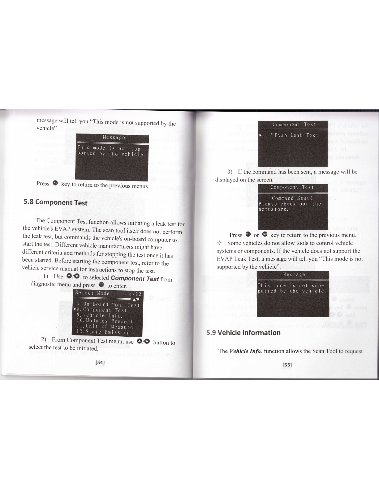
3)
If
the command
has
been sent, a
message will
displayed on the screen.
Press
(B
or
{E
key to return to the
previous
menu.
+
Some vehicles do
not allow tools to control vehicle
systems
or components.
If the vehicle does not support the
EVAP Leak Test, a message will tell
you
"This
mode is not
supported by the vehicle".
5.9
Vehicle lnformation
The
Yehicle
Info. fiinction
allows
bc
Press
(E
key
to
refurn
to
the
previous
menus.
5.8
Component
Test
The
component
Test
function
alrows
initiating
a leak
test
for
the
vehicle's
EvAp
system.
The
scan
toor
itself
do",
,o,
perform
the
leak
test,
but
commands
the
vehicle's
on-board
computer
to
start
the
test.
Different
vehicle
manufacturers
might
have
different
criteria
and
methods
for
stopping
the
test
once
it
has
been
started.
Before
starting
the
component
test,
refer
to
the
vehicle
service
manual
for
instructions
to
stop
the
test.
1)
Use
OA)
to
selected
Componenf
lesf
from
diagnostic
menu
and
press
(E
to
enter.
2)
From
Component
Test
menu,
use
select
the
test
to
be
initiated.
ts4I
OA)
butron
to
I55I
the Scan Totll to rcrpresl
the
vehicle's
vIN number,
calibration
ID(s)
which
identifies
software
version
in
vehicle
control
module(s),
calibration
verification
numbers (cvN(s))
and
in-use
performance
tracking.
I
)
Use
OIO
to
selected
Vehicte
Info.
fromdiagnostic
menu
and
press
B
to
enter.
Select
{E
key, you
will
enter
the
Vehicle
information
press
@
key
return
to
diagnostic
menu.
Iist,
Use
OtO
to
select
an
item
from
Vehicle
Info.
to view
and
prcss
{B
to
enter.
+ If
the
vehicle does
not
support
this mode, a messagc
will tell
you
"This mode is not supported by the vehicle".
3) View the information
you
have selected.
5.10 Modules Present
l'hc
Scan Tool identifies the module IDs
and
communication type
lirr
OBD II modules in the vehicle
1) Use
OIO
to select Modules Present trom
diagnostic menu.
2)
There
is
a
message
comes
up
must
make
a choice
{B
or
@.
to
remind you.
You
4) Press
(E
key to return.
ls6l
tsTl
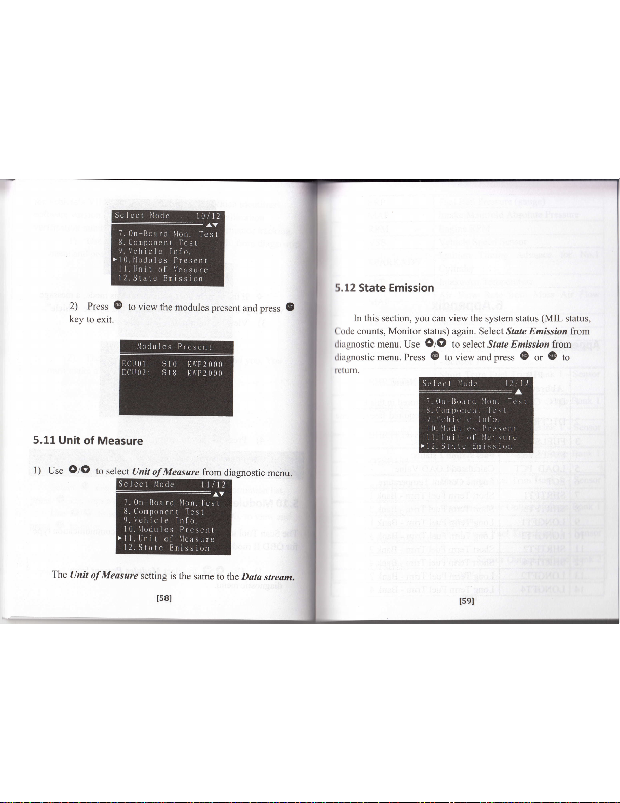
r
2)
Press
G
to
view
the
modules present
and
press
key
to
exit.
5.11
Unit
of
Measure
The
Unit
of Measure
setting
is
the
same
to
the Data
stream.
ts81
5.12 State Emission
In
this section,
you
can view the
system
status
(MIL
status,
('ode
counts, Monitor
status)
again.
Select State
Emission
from
diagnostic
menu.
Use
OIO
to select State Emission from
diagnostic
menu.
Press
(E
to view and
press
@
or
(E
to
re turn.
Isel

r-
6.Appendix
Appendix
l-PtD
List
32
t6u
Fuel
Rail
Pressure
(
lntake Manifold
Absolute Pressure
t7
l8
t9
20
Vehicle
Speed
Sensor
Ignition
Timing Advance
for No.l
Intake
Air
Te
Air
Flow
Rate
from Mass Air
Flow
Sensor
Absolute
Throttle Position
AIR STAT
Oxygen
Sensor
Output
Voltage
Bank I
- Sensor
I
O2SB1S1
Short
Term
Fuel
Trim Bank
1 -
Sensor
1
SHRTFTBlSl
Number
of DTCs
stored
in
this
ECU
Oxygen
Sensor
Output
Voltage Bank I
- Sensor
2
O2SB152
DTC
that
caused
required
freeze
Short
Term
Fuel
Trim Bank
I - Sensor
2
SHRTFTB152
FUELSYS
1
Oxygen
Sensor Output
Voltage
Bank
- Sensor3
Calculated
LOAD
Value
Short
Term
Fuel
Trim Bank I
-
Sensor
3
SHRTFTBl53
Short
Term
Fuel
Trim
-
Bank
I
Short Term
Fuel
Trim -
Bank
3
Oxygen
Sensor
Output
Voltage Bank I
- Sensor
4
LONGFTI
Term
Fuel
Trim
-
Bank
I
Term
Fuel
Trim
- Bank
3
SHRTFTB1
54
Short
Term
Fuel Trim Bank I
-
Scneor
4
Short
Term
Fuel
Trim
-Ba*2
Short
Term
Fuel
Trim
-
Bank
4
Oxygen
Sensor
Output Voltage Bank
2
-
Sensor
I
Term
Fuel
Trim
-Bank2
Term
Fuel
Trim
-
Bank 4

SHRTFTB2SI
Short
Term
Fuel
Trim
Bank
2
_
Oxygen
Sensor
Voltage
Bank
I
-
Sensor
2
(wide
range
O2S
Oxygen
Sensor
Output
Vottug"
nrt
EQ_RATB
I
S3
Equivalence
Ratio
(lambda)
Bank
I
-
Sensor
3
(wide
range
O2S
SHRTFTB252
Short
Term
Fuel
Trim
Brrk
2 -
5l
52
53
54
55
56
57
O2SBIS3
Oxygen
Sensor
Voltage
Bank
I
-
Sensor
3
(wide
range
O2S)
02SB253
Oxygen
Sensor
Output
Voltage
-
Sensor
3
EQ_RATB
I
54
Equivalence
Ratio
(lambda)
Bank
I
-
Sensor
4
(wide
Short
Term
Fuel
Trim
B".k
2
_
O2SBI54
Oxygen
Sensor
Voltage
Bank
I
-
Sensor
4
(wide
range
O2S)
Oxygen
Sensor
Output
Voftug.
ernt
-
Sensor
4
EQ_RATB2SI
Equivalence
Ratio (lambda)
Bank
2
-
Sensor
I
(wide
Short
Term
Fuel
Trim
Bank
2
_
Oxygen
Sensor
Voltage
Bank
2
-
Sensor
1
(wide
range
O2S)
OBD
requirements
to
rt
i"t
l.t
irt.
Equivalence
Ratio
(lambda)
Bank
2
-
lpqsor
2
(wide
range
O2S)
Power
Take
Off (pTO)
St"tu.
Oxygen
Sensor
Voltage
Bank
z
Sensor
2
(wide
range
O2S)
Time
Since
Engine
Start
Distance
rruu.Ura-
WhG--tutit
Equivalence
Ratio
(lambda)
Bank
2
-
Sensor
3
(wide
range
O2S)
Fuel
Rail
pressure
."trriu.
to
*-
02S82S3
Oxygen
Sensor
Voltage
Bank
2
Sensor
3
(wide
range
O2S
Fuel
Rail
Pressure
Equivalence
Ratio
(lambda)
Bank
2
-
Sensor
4
(wide
range
O2S
EQ_RATBISt
Equivalence
Rario
(fibdu)
Burkl
Sensor
I
(wide
Oxygen
Sensor
Voltage
Bank
2
Sensor
4
(wide
O2SBISI
Oxygen
Sensor
\,m
Sensor
I
(wide
range
O2S
EQ_RATBls2
Equivalenc"
Rutio@
Sensor
2
(wide
EGR-ERR
EGR
Error (EGR
actual
.EGR
commanded)
/ EGR
commandgd)
r
100
Y"

t6sl
Sensor
2
(wide
range
O2S)
81
O2SB252
Oxygen
Sensor
Voltage
Bank
2
-
Sensor
2
(wide
range O2S)
82
EQ_RArB2S3
Equivalence
Ratio
(lambda)
Bank
2
-
Sensor
3
(wide
range O2S)
83 O2SB233
Oxygen
Sensor
Voltage
Bank
2
Sensor
3
(wide range O2S)
84
EQ_RATB254
Equivalence
Ratio
(lambda)
Bank
2
-
Sensor
4
(wide
range O2S)
85 O2SB254
Oxygen
Sensor
Voltage
Bank
Sensor
4
(wide
range O2S)
2
86
CATEMP1
l
Catalyst
Temperature
Bank
l+Sensor I
87 CATEMP2I
Catalvst
Temperature
Bank
2tSensor
I
88
CATEMP12
Catalvst
Temperature
Bank
l+Sensor 2
89 CATEMP22
Catalyst
Temperature
Bank
2+!qqqg!Z
90
VPWR
Control
module
voltage
91 LOAD
ABS
Absolute
Load
Value
92
EQ-RAT
Commanded
Equivalence
Ratio
93
TPR
Relative
Throttle
Position
94
AAT
Ambient
air
temperature
(same
scaling
as IAT
-
$0F)
95
TPB
Absolute
Throttle
Position
B
96
TPC
Absolute
Throttle
Position C
97
APP D
Accelerator
Pedal
Position
D
98
APP E
Accelerator
Pedal
Position E
99
APP F
Accelerator
Pedal
Position F
100 TAC
PCT
Commanded
Throttle
Actuator
Control
101
MIL
TIME
Time
run
by
the engine
while
MIL
ic
activated
Commanded
Evaporative
Pu
Fuel
Level
Input
Number
of warm-ups
since
di
trouble
codes
cleared
Distance
since
diagnostic
trouble
cleared
EQ_RATBISl
Equivalence
Ratio
(lambda)
Bank
1
Sensor
1
(wide
range
O2S)
O2SBlSI
Oxygen
Sensor
Voltage
Bank
I
Sensor
I
(wide
range
O2S)
EQ_RATB152
Equivalence
Ratio
(ambda)
Bank
I
Sensor
2
(wide
range
O2S)
O2SB152
Oxygen
Sensor
Voltage
Bank
I
Sensor
2
(wide
range
O2S)
EQ_RATB1S3
Equivalence
Ratio
(lambda)
Bank
I
Sensor
3
(wide
range
O2S)
Oxygen
Sensor
Voltage
Bank
I
Sensor
3
(wide
range
O2S
EQ_RATBl54
Equivalence
Ratio
(lambda)
Bank
I
Sensor 4
(wide
range
O2S
O2SBI54
Oxygen
Sensor
Voltage
Bank
I
Sensor
4
(wide
range
O2S
Equivalence
Ratio
Qambda)
Barlr.
2
Sensor I
(wide
range
02
Oxygen
Sensor
Voltage
Bank
2
Sensor I
(wide
range
O2S
164l

119
120
t2l
tn
123
t24
t25
r26
t27
128
t29
130
l3l
132
r33
t34
135
136
137
138
r39
140
167l
CLR_TIME
Time
since
diagnostic
trouble
cleared
Fuel svstem
moni
Comprehensive
component monitoring
Type
of
fuel
currently
being
utilized
the
vehicle
Misfire
monito
MIS RDY
Alcohol
Fuel
Percenta
Fuel system
monitort
Absolute
Evap
System
Va
Pressure
Comprehensive
component monitoring
Evap
System
V
Catalyst
monitori
CAT
SUP
STSO2FTI
Short
Term
Secondary
02
Sensor
Trim
-
Bank
1
Heated
catalyst
monitorin
HCAT SUP
Evaporative
system
monitoring
Short
Term
Secondary
02
Sensor
F
Trim
-
Bank
3
Secondary
air system
Long
Term
Secondary
02
Sensor
F
Trim -
Bank
1
AIC system
refrigerant
monitoring
Long
Term
Secondary
O2
Sensor
Fue
Trim
-
Bank
3
Oxvgen
sensor
mon
O2S SUP
Short
Term
Secondary
02
Sensor
F
Trim
-
Bank2
Oxygen
sensor
heater
Short
Term
Secondary
02
Sensor
F
Trim
-
Bank
4
EGR svstem
monito
Catalyst
monitoring
read
CAT
RDY
Long
Term
Secondary
02
Sensor
F
Trim
-
Bank
2
Heated catalyst
monitoring
read
Evaporative
system
moni
EVAP
RDY
Long
Term
Secondary
O2
Sensor
F
Trim -
Bank
4
Secondary
air system
monitori
AIC system
refrigerant monitoring
Fuel
Rail
Pressure
(absolute
Relative
Accelerator
pedal
position
O2S RDY Oxygen
sensor
Malfunction
Indicator
Lamp
(MIL)
EGR svstem
monitori
Misfire
monitori
MIS ENA
Misfire
monitorins
enabled
t661

Appendix
2 ln-use
Performance Tracking
Data
Abbreviation Full Name
Definitions
OBDCOND
OBD
Monitoring
Conditions
Encountered
Counts
OBD Monitoring
Conditions
Encountered
Counts
displays the number
of times
that the vehicle
has
been operated in
the
specified OBD
monitoring
conditions
(general
denominator).
IGNCNTR
Ignition
Counter
Ignition Counter displays
the count
of the number
of
times
that the engine has
been started.
(:ATCOMPl
Catalyst
Monitor
Completion
Counts Bank
Catalyst
Monitor
Completion Counts
Bank
displays
the number
of
times that all conditions
necessary to
detect a
catalyst
system
bank I
malfunction have
bccn
encountered
(numctabr).
I6el
FUEL
ENA
Fuel
system
monitoring
enabled
Comprehensive
component
moni
enabled
MIS
CMPL
Misfire
monitoring
comoleted
Fuel
system
monitoring
completed
Comprehensive
component
monitori
CAT
ENA
HCAT
ENA
Heated
catalyst
monitori
EVAP
ENA
Evaporative
system
monitorin
AIR
ENA
Oxygen
sensor
moni
Oxygen
sensor
heater
monitori
Heated
catalyst
monitorine
com
Evaporative
system
AIR_CMPL
Secondary
air
system
monitori
NC
system
refrigerant
monitori
O2S
CMPL
Oxygen
sensor
monitoring
completed
Oxygen
sensor
heater
monitori
EGR
system
monitoring
completed

171l
CATCONDI
Catalyst
Monitor
Conditions
Encountered
Counts
Bank
I
Catalyst
Monitor
Condi
Encountered
Counts
Bank
displays
the
number
of
times
that
the
vehicle
hasl
been
operated
in
the
;
specified
catalyst
monitoring
conditions
(denominator
been encountered
(numerator).
O2SCONDl
02 Sensor
Monitor
Conditions
Encountered
Counts
Bank I
02 Sensor
Monitor
Conditions
Encountered
Counts
Bank I displays the
number of times that
the
vehicle
has been operated
in
the specified
oxygen sensor
monitoring conditions
denominator
CATCOMP2
Catalyst
Monitor
Completion
Counts
Bank
2
Catalyst
Monitor
Completion
Counts
Bank
displays
the
number
of
ti
that
all
conditions
necessan
to
detect
a catalyst
system
ba*2
malfunction
have
been
encciuntered
O2 Sensor
Monitor
Completion
Counts
Bank
2
02
Sensor
Monitor
Completion
Counts Bank 2
displays
the number of time
that
all conditions necessary
to detect an
oxygen
sensor
bank2 malfunction
have
been encountered
(numerator).
O2SCOMP2
CATCOND2
Catalyst
Monitor
Conditions
Encountered
Counts
Bank
2
Catalyst
Monitor
Conditi
Encountered
Counts
Bank
displays
the
number
of
times
that
the
vehicle
has
been
operated
in
the
specified
catalyst
monitoring
conditions
02 Sensor
Monitor
Conditions
Encountered
Counts Bank 2
02 Sensor
Monitor
Conditions
Encountered
Counts
Bank 2 displays the
number of times that the
vehicle
has
been operated in
the specified oxygen sensor
monitoring conditionr
O2SCOND2
O2SCOMPl
02
Sensor
Monitor
Completion
Counts
Bank
1
02
Sensor
Monitor
Completion
Counts
Bank
I
displays
the
number
of
time
that
all
conditions
necessaq/
to
detect
an
oxygen
sensor
bank
I
malfunction
have

EGRCOMP
EGR
Monitor
Completion
Condition
Counts
EGR
Monitor
Completionll
Condition
Counts
displays
the
number
of time
that
all
conditions
necessary
to
detect
an EGR
system
i
malfunction
have
been
.ir
encountered
(numerator).
J
I I I
evaP
Monitor
Completion
l
I I I
Condition
Counts
displays
I
I I EvAP Monitor I
trre number
of time
that all
I
l,uo,.o*, I
'.#*:lr
I
u::l:';ffiffi[r
I
I I
Counts
I
system
leak maltunction
I
I I Inavei,"fr:*T;:"-'l
I I I Encountered
Counts
I
I I I
oi*ptuys
the
number of
I
I I
EVAP
Monitor
I ti*.,
that
the vehicle
has
I
lu,o,.o^, |
#;lli:li
I
u..,:il:?l:1*,n.
I
I t
counts
I
uuoP
system
leak
I
I I I
malfunction
monitoring
I
|
|
|
conditions
(denominator).
I
173l
EGRCOND
EGR
Monitor
Conditions
Encountered
Counts
EGR
Monitor
Conditions
Encountered
Counts
displays
the
number
of
times
that
the
vehicle
has
been
operated
in
the
specified
EGR
system
monitoring
conditions
(denominator).
AIRCOMP
AIR
Monitor
Completion
Condition
Counts
(Secondary
Air)
AIR
Monitor
Completion
,j
Condition
Counts
I
(Secondary
Air)
displays
tho
number
of time
that
all
conditions
necessary
to
detect
an
AIR
system
malfunction
have
been
.
encountered (numerator).
AIRCOND
AIR
Monitor
Conditions
Encountered
Counts
(Secondary
Air)
AIR
Monitor
Conditions
Encountered
Counts
(Secondary
Air)
displays
the
number
of
times
that
the
vehicle
has
been
operated
in
the
specified
AIR
system
monitoring
conditions
t72l

Appendix
3
l/M
Readiness
List
Appendix
4
.
Vehicle Manufacturer
Number
23
24
25
I75I
FuIl
Name
Vehicle
Manufacturer
Catalyst
monitoring
J
4
I
I
7
Heated
catalyst
monitoring
Evaporative
system
monitoring
Secondary
air
system
monitoring
A/C
system
refrigerant
monitoring
Oxygen
sensor
monitoring
Oxygen
sensor
heater
monitoring
15
t6
l1
18
t9
20
2l
22
EGR
system
monitoring
Misfire
monitoring
Fuel
system
Comprehensive
component
monitoring
1741

55
Roll Royce
56
Rover
57
Saab
58
Saturn
59
Scania
60
Seat
61
Skoda
62
Smart
63
Ssangyong
64
Subaru
65
Suzuki
66
Toyota
67
Vauxhall
68
Volvo
69
Volkswagen
177l
Iveco
Kia
Lambor
Land
Rover
Lanos
Lotus
Maserati
Mazada
Mini
Mitsubishi
Nissan
Nubira
Oldsmobile
Opel
Porsche
Renault

j
oro"rr,-
;
;;;,r,
,oor"viation
or
vgatescan
7.
Warranty
and
Service
7.1 Limited
One Year
Warranty
vgatescan
warrants
to its
customers
that this product
will
be
fiee
from
all
defects
in
materials
and
workmanship
for
a
period
of
one year
from
the
date
of
the
original purchase,
subject
to the
following
terms
and
conditions:
l)
The
sole
responsibility
of
vgatescan
under
the
warranty
is
limited
to
either
the repair
or, at
the
option
of
Vgatescan,
replacement
of
the
scan
tool
at no
charge
with
proof
of
Purchase.
The
sales receipt
may
be
used for
this purpose.
2) This
warranty
does not
apply
to
damages
caused
by
improper
use,
accident,
flood,
lightning,
or if the product
waq
altered
or repaired
by
anyone
other
than
the
Manufacfurer's
Service
Center.
3)
Vgatescan
shall
not
be
liable
for
any
incidental
or
consequential
damages
arising
from
the
use,
misuse,
or
mounting
of
the
scan
tool.
Some
states
do
not
allow
limitations
on how
long
an
implied
warranty
lasts,
so
the
above
limitations
may not
apply
to
you.
4)
All
information
in
this
manual
is
based
on
the latest
information
available
at
the time
of
publication
and no
warranty
can
be made
for
its
accuracy
or completeness.
Vgatescan
reserves
the right
to
make
changes
aiany
time
without
notice.
lTel
Not
available
not
applicaG
Vehicle
Manufacture
Parameter
Identifier
Vehicle
Info. \r'ehicle
Information
Diagnostic
trouble
codes
Electronic
control
unit
CID (On
Board
Monitor)
Calibration
Identifier
Measured
Value
Minimum
Vehicle
ID
Number
Calibration
Verifi
cation
]!:qq
Performance
Tracki
02
Bank
X-Sensor
y
Oxygen
Sensor
Monitor
B.rk
X
-
Sensor
y
Catalysr
Mon.
B
X
Catalyst
Monitor
Bank
X
ITBI

If
it
becomes
necessary to
return
the scan
tool
for repair,
contact
your
local,distributor
for
more
information.
'
i
I80l
 Loading...