

Page 1

P
ANORAMATIC
(
panoram
User’s manual
Underwater
DROP VIDEO
C
at
ic UNDERWATER camera
Vápenická 24, 971 01 Prievidza
Tel/Fax
http://www.vftech.sk
AMERA
)
VFTECH s.r.o.
Slovakia
+421 46 5426456
Page 2

v01/2017
TABLE OF CONTENTS
2
List of abbreviations ……….……………………………………… 3
Introduction to the Operation Manual ………………………… 4
1. Purpose and Scope …………………………………………….. 5
2. Requirements for the location and climatic operating conditions .... 6
3. Desing …………………………………………………………… 8
4. Technical specifications ………………………….....………. 11
5. Electrical characteristics and performance parameters ........ 12
6. Measures to ensure safety in preparation for work ................ 13
7. Electrical connections and connecting additional devices ...... 15
8. Preparing for the job and how to connect
8.1 Preparing for the job and how to connect …............……… 16
8.2 Block diagram of the camera connection …………………… 19
8.3 Key functions and work with the system …………………… 21
8.4 Options to connect the controller to a different power source…… 24
8.5 Fuses in the assembly video systema ……………………… 25
8.6 Screen …………………………………………………………. 26
9. Maitenance …………………………………………………………. 27
10. Retention rules, transportation and disposal ………………… 28
11. Service life and warranty …………………….…………………… 29
APPENDIX ……………………………………………………………. 30
Page 3

v01/2017
3
LIST OF ABBREVIATIONS
Hazardous voltage 230V / 50Hz
Please read these instructions
before use. In case of problems
consult a qualified specialist.
List of abbreviations
UPC – underwater panoramic camera
SCM – surface control module
Page 4

v01/2017
4
INTRODUCTION TO THE OPERATION
The guide should always be available to all persons who work with this camera
When using UPC "GNOME" follow these instructions in accordance with international
standards:
Safety – ГОСТ Р МЭК 60065-2002 (IEC 60065)
Electromagnetic compatibility - ГОСТ Р 51317.6.1, ГОСТ Р 51317.6.3-99
Certificate of conformity
In addition to these guidelines, you have to respect the laws and regulations in force in each
country, as well as the rules and regulations applicable to work under water in the place of
work.
Sale or transfer of UPC "GNOME" to other persons may be performed only in conjunction
with this instructions. In this case, the potential risks of the operation are transferred to the
new UPC purchaser (user).
This manual is intended to inform the user with a view to ensuring its correct and safe
operation.
Self-opening system components, mechanical damage and violation of modules may cause
malfunctions of the complex.
Before turning on the system, read this manual and familiarize yourself with the controls.
Within the context of continuing evolution of the video system, that increases reliability and
improves performance, there can be made small changes which are not described in this
manual.
Page 5

v01/2017
5
1. PURPOSE AND SCOPE
Video system is designed for scanning an object under water as well as control objects above
the water in different climatic conditions. Color image is transmitted by cable and the you
see the scanned image on the monitor.
The main areas of application are:
• Diving
• Fishing
• Caving
Page 6

v01/2017
6
2. REQUIREMENTS FOR THE LOCATION ..
Requirements for the location and climatic operating
conditions
Conditions and procedures for the use of UPC - minimize the risk of threats and damage
caused by Panoramic camera UPC during the whole period of work.
Power socket, control unit and cable reel must be protected:
• From direct exposure to precipitation (rain, snow, dew)
• From the damaging effects by animals, rodents and insects
• From contact with water or drowning
• From the careless actions on the part of unauthorized persons
At ambient temperature more than +20° the control unit must be protected
from solar radiation overheating.
At first signs of approaching storm, immediately stop underwater operations and remove
the plug from the socket of the control unit.
It is forbidden to leave the plug in the socket after use.
UPC is designed for use in following climatic conditions:
• Ambient air temperature (-20 +45) °С
• Relative humidity up to 98% non-condensing
• Atmospheric pressure from 84 to 106.7 kPa (630-800 mm Hg. M)
Wire harness which links underwater module with control unit is functional at the air
temperature: - 20 to 45 ° C and the water temperature: - 5 ° C to 45 ° C.
Page 7

v01/2017
7
3. DESING
The assembly consists of underwater UPC module, wiring harness and the control / power
module SCM. UPC is a waterproof module. In the middle part of the body is a plexiglas
cylinder, where are stored horizontal cameras and LED lighting. At the bottom of UPC may
be (depending on configuration) aperture for vertical camera with LED svetloma. At the top
of the UPC is connector for plugging, pressure sensor and cable clamps. Inside the UPC are
installed 3 (4) color video camera CCD 1/3 "rings with LED lights, power inverter and
electronic block.
The control / power module performs the function of underwater module communications
(his power) and processing output data from UPC (information storage). It is equipped with
the appropriate connectors to link with the required modules (UPC, video recorder,
monitor). There are installed control of the brightness of LED lighting, control of sensors and
circuit breaker.
UPC is connected via coaxial cable to SCM, which provides the power supply (180V), control
processes information from sensors and video from the cameras. SCM is a stand-alone
module or can be installed in a waterproof case. It consists of a supply unit and control
electronics. You can connect any LCD monitor 8-15 ".
You can connect to it simultaneously video recorder and have connected LCD monitor. The
module comprises a standard CINCH video connector to RCA cable. You can also connect to a
PC with COM interface.
Page 8
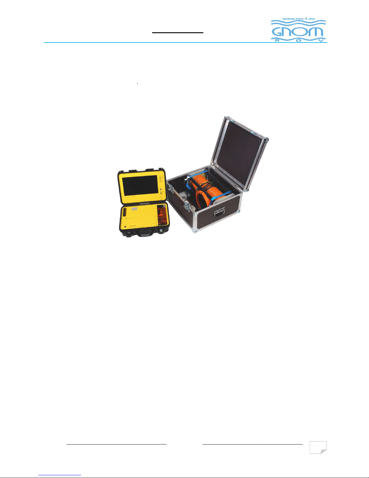
The basic kit with accessories
Basic kit of panoramic camera:
- Underwater module UPC
-
Topsite module/Surface control module SCM
- Wire Harness 50 m
Additional modules (optional):
- Cable - extension up
to 300 m
- Reel with slip rings
- Inverter
- Battery
- Connecting cables
- Monitor / TV
- Video recorder
- Video image corrector
v01/2017
3. DESING
The basic kit with accessories
8
Page 9

v01/2017
9
3. DESING
Please note that all information concerning the equipment modules, technical specification
is for information only. For more information contact the Sales Department.
To record video taken during the work you can use following devices:
• VCR
• Devices with writing to the hard disk
• Video cameras with external video input signal
• A computer with a module for recording and video processing
s
All kinds of additional equipment should have the appropriate operating
instructions with technical data from the manufacturer for the smooth and
safe operation.
Page 10

v01/2017
10
4. TECHNICAL SPECIFICATIONS
Operating depth
300m
Cable lenght
Up to 300m
Cable type
special reinforced Kevlar fibers in polyethylene
containment isolation, with negative buoyancy.
Mass of air 40 g / m, in water 10 g / m
Cable diameter
7 mm
Cable capacity
100 kg, functional damage may occur with load
of 35 kg
Lighting
60 or 105 strong bright LEDs (white light)
Video camera
PAL CCD, 480TVL, 0.5LUX
Video system with lighting ensures visibility up to 20 m (depending on light levels and water
clarity). When you turn on the camera light to full power in the clear water in the dark (no
ambient light) it is 3-4 m visibility.
Depth sensor with output information on the monitor in the "teletext"
Compass with output information on the monitor in the "teletext"
Power and controle module
Power supply
230V 50-60 Hz
Max. power consumption ( at
cable length up to 50 m )
35 W
Max. power consumption (at
cable length 300 m)
No more then 100 W
Environment humidity
Up to 100%
Operating temperature range
- 20 …+ 45°С
Weight of underwater module
700g
Set weight (with 50 m cable.)
12 kg
Dimensions of underwater
module
190mm х 90mm х 90mm
Constructional option
portable
Note:
Cable length can vary according to the customer requirements.
Page 11

v01/2017
11
5. ELECTRICAL CHARACTERISTICS
Electrical characteristics and performance parameters
You can power UPC in two ways:
а) from single-phase 230 V 50 with ground wire
Topside module is fully functional in voltage range from 198 V to 242 V
b) from external power supply 12V = with DC inverter to 230 VAC.
Performance power supply depends on the features of underwater module.
The power cable is a part of the control / power module
Phase-pin mains plug has color coding
Do not replace the power cord for another one without prior inspection!
Page 12
v01/2017
12
6. MEASURES TO ENSURE SAFETY ...
Measures to ensure safety in preparation for work
To minimize the risk of physical damage to the panoramic camera GNOM
assembly and to avoid dangerous situations, do not allow to children, persons
under the influence of alcohol or drugs, mentally unstable persons or persons
with extreme behavior to manipulate with the device.
After placing the assembly panoramic camera from a cold to a warm place with a
temperature difference of 10º C, you are required to wait at least four hours before work in
new conditions.
Connecting to AC power 230V
The socket at the place of operation UPC, the power cord and plug must be intact,
structurally and technically compatible (must meet the requirements of normal).
Do not connect cameras and other auxiliary equipment to a power source if
the following problems:
• bi-socket, bi-strip, two-wire extension cord
• The power cord has a changed to the two wires or is connected to two wires extension
cable.
• Used bipolar socket in which:
Ochranný vodič (PE-vodič) je odpojený
Nesprávne zapojené vodiče L a N
• If you suspect an incorrect connection sockets - installation errors (human factor). It is a
possibility while protective conductor or conductors incorrectly connected phases and NUL
(L and N)
Page 13

6. MEASURES TO ENSURE SAFETY ...
Do not turn on / turn off the power supply device (230) at frequent intervals
than 5 seconds
During and after
working with the panoramic camera set up, it is necessary to transfer
control device and check the following security features:
• damage to the insulation of the connection cable as well as power cables
• fever or overheating of the insulating material in
Identification and removal of defects in the wiring outlets and extension cords should be
carried out in the presence of a qualified person
7. E
LECTRICAL CONNECTIONS AND CONNECTING
ADDITIONAL DEVICES
Additional modules to
the supply voltage 230 must be carried out only through an extension
cord in a design according to current standards.
By the time work with the fraudulent module must not be connected to an
extension cord with no heating and lighting, as well as any
v01/2017
connectors, sockets / plugs
13
Page 14

8. PREPARING FOR THE JOB AND HOW TO
Preparing for the job and how to connect
Be careful when handling the harness:
tension in the cable is 180V!
Before starting work with the camera as well as after work carefully
check the wiring harness, especially the integrity of insulation
Do not use the device if you are not connected to a power point with a
Cable
requires careful handling:
• It is forbidden to place any objects on the cable and soar beyond
• Avoid contact with sharp objects Cable
• Do not kink the cable and do not make it to the nodes.
When detecting external damage to cable insulation
v01/2017
CONNECT
protective earthing circuit..
.
immediately.
14
Page 15

8. PREPARING FOR THE JOB AND HOW TO
1.
Check that the plexiglas visors clean.
2.
From the wiring harness (from reel) unroll the required length of cable.
3. 10-pin cable
connector connect to the underwater module and secure clasp. Connect the
other end to the cable to above
Reel without slip rings
Do not turn the reel when connector of connecting cable is connected reel /
above-water unit
If necessary unwinding of the cable during operation, turn off the system,
disconnect the connector connecting cable reel / above
required quantity of cable and connect everything back
4.
When using an external monitor or VCR, connect video output of control unit to the input
of the monitor or VCR
5
. The panoramic camera is ready to work.
6.
To turn on the video set, switch “230 V” to the ON position "|". If everything is in order,
on th
e front panel LED lights "связь" (connection).
On the air do not set up the maximum brightness in underwater lighting
7
. Use the 3.4 "Свет" (light) to regulate the brightness in underwater module.
8. After
finish of work rinse underwater module in clean water. Wind the cable on the reel.
Be careful to not create nodes. Do not twist the cable.
9.
Before packing modules into transport packaging dry carefully all the components.
v01/2017
CONNECT
-water unit (control / power module).
-
-
water unit, unroll
module!
15
Page 16

v01/2017
16
8. PREPARING FOR THE JOB AND HOW TO CONNECT
Disconnect the connectors when the power supply is turned off!
Coil the cable on the reel carefully. Any knots or twist on the cable unwind
carefully.
Page 17
v01/2017
17
8. PREPARING FOR THE JOB AND HOW TO CONNECT
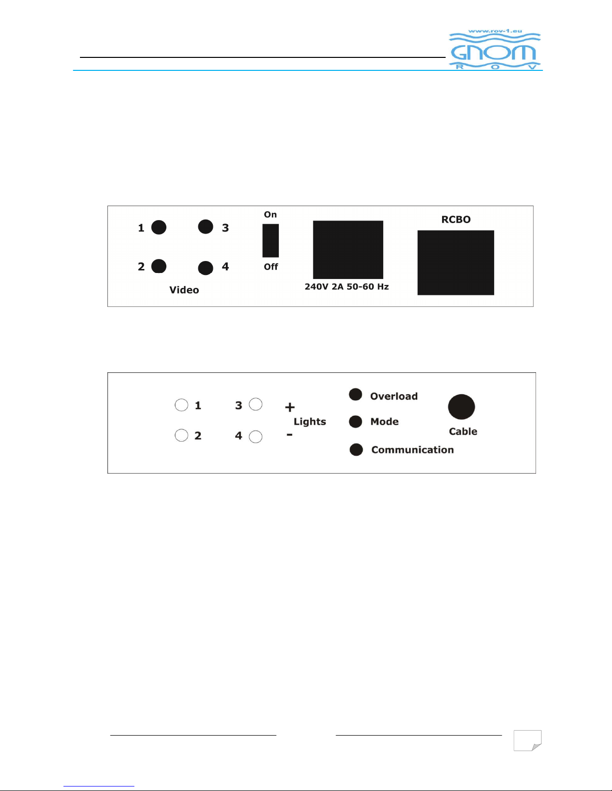
8.2
Block diagram of the camera connection – surface control
2.1. Surface control – in basic set UPC
Piс. 1 Back panel of the surface control
Piс. 2 Front panel of the surface control
Page 18
v01/2017
18
8. PREPARING FOR THE JOB AND HOW TO CONNECT
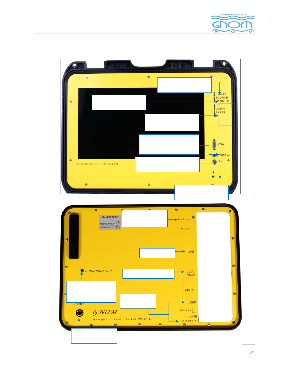
2.2. Surface control – in the expanded configuration
ON/OFF
power
Choice of video input
MENU – display
settings
Input VGA display
(Using a computer)
Power supply display
Video Input Display
USB Hub
Output power
for display
VGA/HDMI output
ON/OFF SCM
Outlet cable from
Indicator
(communications)
UPC and SCM
Page 19

8. PREPARING FOR THE JOB AND HOW TO
8.3
Control (keyboards) and work with System
3.1.
video Output
"1", "2", "3" video outputs of a horizontal video camera (pic.1)
Sensor data depth and compass are
transmitted only from the video output "1"
"4" video output from the vertical camera
3.2.
Adjusting the brightness of the lighting.
To increase the brightness of the LEDs need to press or press and hold the "3" (+
screen displays information about the brightness percentage.
To reduce the brightness of the LEDs need to press or press and hold the "4" (light
screen displays information about the brightness percentage.
To turn on or turn off the
lights completely, briefly press both buttons simultaneously, "3"
and "4".
3.3.
Sensor calibration depth (optional module)
Performing this operation the operator can lead to
malfunctioning of the sensor depth. Convert this function only after
consultation with the manufacturer.
To set the value to zero air. Hold for at least 3 seconds the button "1". On the screen shou
appear value of 0.0 m depth. Then release the "1".
v01/2017
CONNECT
.
19
light). The
-). The
ld
Page 20

8. PREPARING FOR THE JOB AND HOW TO
When calibrating the sensor in water depth, follow these steps:
1.
Immerse the fraudulent module into the water at the depth that you know
2.
Press and hold for at least 3 seconds, the "2"
3. the "3" and "4" (+/
-
4.
If you have a value set, press and hold for at least 3 seconds, press "2" for writing the
set value
3.4.
Compass calibration (optional module)
Performing this
of the compass. Convert this function only after consultation with the
manufacturer.
To enter the calibration mode, press and hold for at least 3 seconds Press "1" and "2".
To a monitor, you will see
information on the entry into the compass calibration, then
continue:
1. Release the buttons "1" and "2"
2. Turn on the camera 360 degrees around a vertical axis for about 2
(while the compass recalibrated)
3. Press and hold again for at least 3
exit calibration mode calibration.
Compass calibration should be performed in the absence of magnetic
materials and electromagnetic fields that can distort measurements and lead
to maladjustment.
v01/2017
CONNECT
operation the operator can lead to malfunctioning
seconds the buttons "1" and "2" for entry and
20
-4 seconds
Page 21

v01/2017
21
8. PREPARING FOR THE JOB AND HOW TO CONNECT
3.5.
Set time and date
To set the time and date, press "2". To a monitor, you will see information on the entry to
the time and date settings. Then follow these steps:
1. Press "2" - selection parameter (the parameter being set will flash)
2. Press "3" or "4" to increase or decrease the value of selected parameter
3. Press "1" to save the settings and exit setup
3.6.
The current protection.
Turn off the power if the system detects leakage current (eg. If the cable is damaged, its
isolation ...). If it is a false evaluation, turn on the circuit breaker. With repeated off-leakage
circuit breaker, disconnect the device from the power supply and contact the manufacturer.
Page 22

v01/2017
22
8. PREPARING FOR THE JOB AND HOW TO CONNECT
8.4 Versions connection control module to different types
of power supply
4.1
Connection to the mains supply ~230 V, 50 Hz
Connect the power cord that came with the control module in the control module.
Connect the other end of the power cord to the network ~ 230V, 50 Hz
4.2
Connecting to the generator AC voltage 230V ~ 50Hz
Connect the power cord that came with the control module in the control module.
Connect the other end of the power cord to the generator AC voltage 230V ~ 50Hz.
4.3 Connection to the battery 12V via the inverter voltage
12V / 230V 50Hz with power min. 700W
Connect the inverter to the battery 12V using the appropriate cables.
Connect the power cord that came with the control module in the control module
Connect the other end of the power cable to the inverter
Page 23
v01/2017
23
8. PREPARING FOR THE JOB AND HOW TO CONNECT
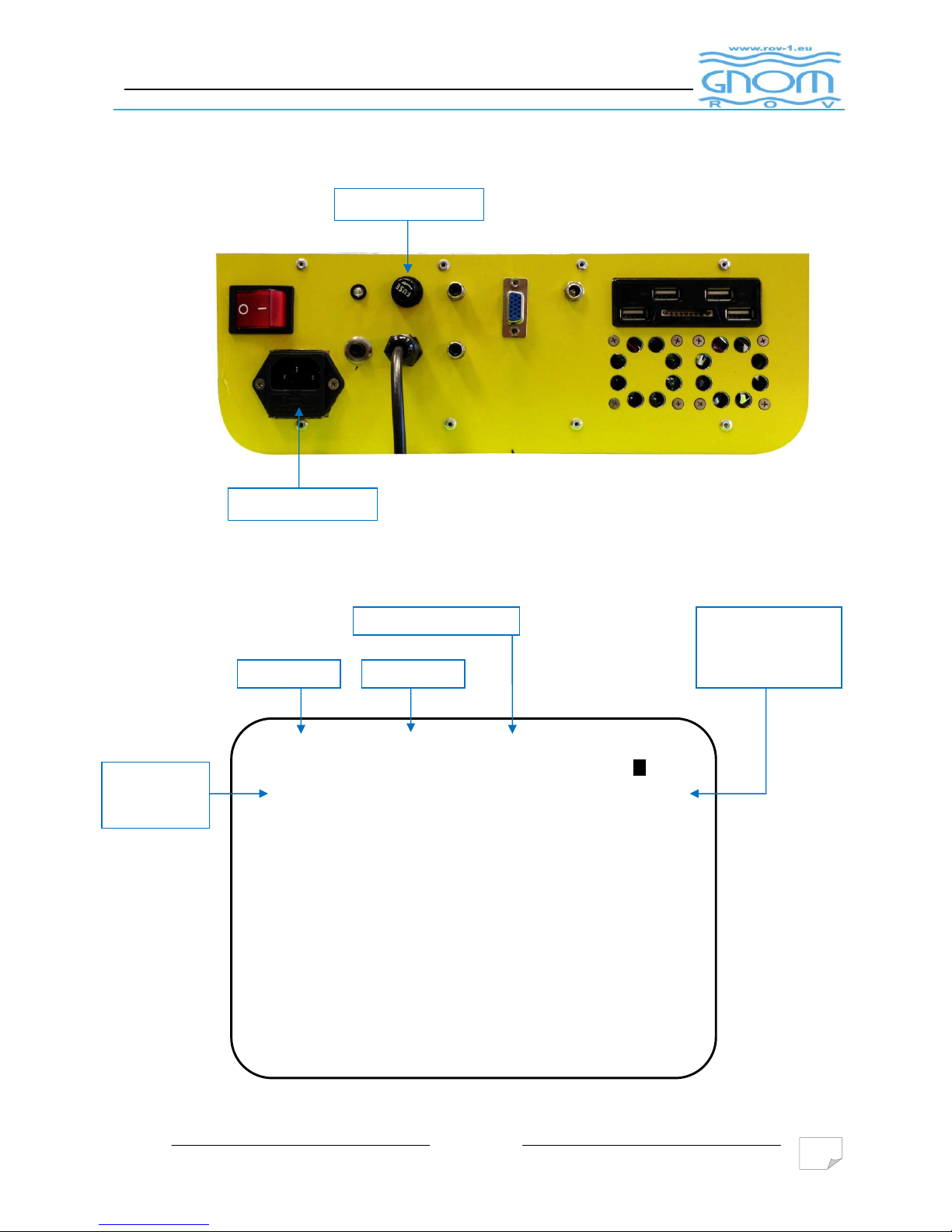
8.5 The fuses in the control / power supply module
8.6 Screen (information from UPS)
150
W
E
S
N
Light1: full
10.4m
30 Jul
13:40:3
Current depth UPC
Actual
brightness of
Time
Date
Schematic
representation and
the exact value
compass
Fuse
Fuse
Page 24

v01/2017
24
9. MAITENANCE
9.1
For 100% functionality maximum equipment life follow:
Check the cord after work. In the case damage has been found (damaged insulation,
twisted-pair cable ...) immediately remove these defects. If this is not possible, please
ask for help from the manufacturer or a qualified professional.
Avoid the nodes or twisted cable
After work, rinse the underwater module in pure freshwater
Page 25

v01/2017
25
10. RETENTIONS RULES, TRANSPORTATIN ...
Rules for storage, transportation and disposal
10.1 Packages panoramic camera modules can be transported by all modes of transport and
must be protected from direct exposure to rain and mechanical damage.
10.2 Cargo can and ambient temperatures of up to -20о 45оС.
10.3 Packaged modules can be transported by all types of passenger vehicles
10.4 Modules panoramic camera should be stored under conditions where the air contains no
acid vapors or other corrosive elements. The air temperature in the storage areas should
range from 5о to 40оС and humidity of 40-85% without rapid change.
10.5 The storage time camera module should not exceed a period of two years.
10.6 Disposal camera module provided by the manufacturer or a specialized company for
recycling of electrical products
Page 26

v01/2017
26
APPENDIX
Durability and warranty
11.1 Durability panoramic camera modules is determined by the manufacturer
5 years under the following conditions:
The user has complied with all recommendations and requirements for the transport,
storage and operation of the panoramic camera
During this period, the camera module are not exposed to harmful forces
respectively. exposed through force majeure (lightning, flood ...)
The user performs routine inspections and regular maintenance.
11.2 The warranty period is one year from the date of delivery to the customer the camera.
During the warranty period, the manufacturer ensures free removal of hidden defects
that occur in the process of operating the camera.
11.3 The warranty period is automatically extended by the time that the camera is in
warranty repair from the manufacturer.
Risk of damage to the camera (modules) from the use of additional modules without
identifying the manufacturer bears the buyer (user) cameras.
11.4 The manufacturer's warranty does not cover the following items supplied as part of the
camera:
Wire harness
These elements are under the influence of uncontrolled events under the water surface as
well. (Insulation damage, jammed cable, the cable congestion ...).
Page 27

v01/2017
27
APPENDIX
APPENDIX
Page 28
GnomRov.ru
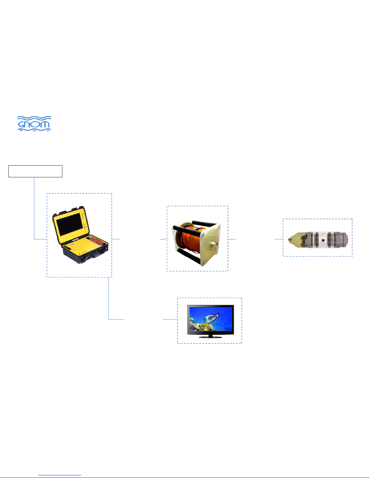
Block diagram power, control and video signal
APPENDIX 1
Underwater
module
Panoramatic
camera
Reel with cable (tether)
Surface module
~230V, 50Hz
Monitor, video recorder...
video output
RCA (CINCH)
HDMI, VGA
180V power
cord, control
and video signal
Connecting
cable- tether
Page 29
GnomRov.ru
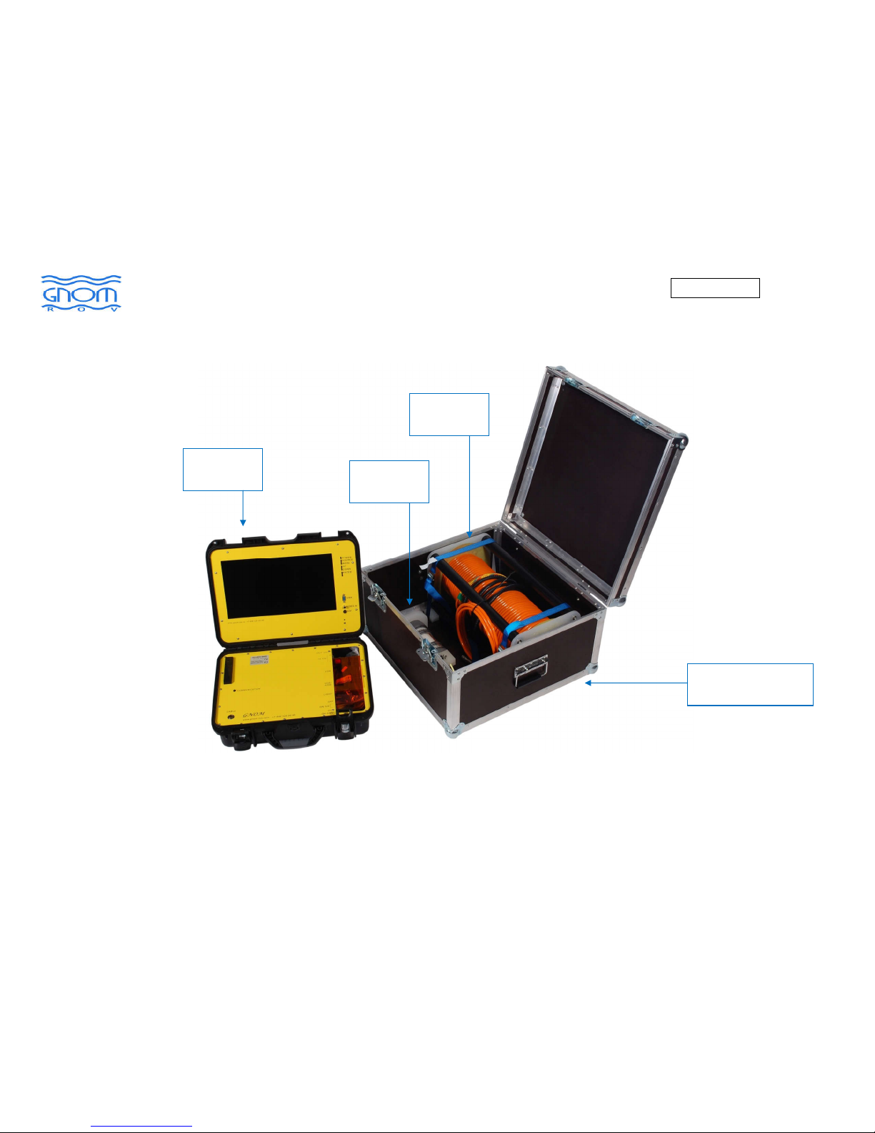
Panoramic camera - Panoramic DCAM (tethered) "GNOM" - illustrative photo kits
Surface unit
Underwater
unit
Reel with
tether
Protective carrying
case - cover
APPENDIX 2
Page 30

GnomRovu.ru
Наши контакты:
ООО «Подводная робототехника»
тел. +7(495)970-93-89, +7(499)129-20-45
[email protected]
http://www.gnomrov.ru
Нахимовский пр. 36
г. Москва
117997, Россия
 Loading...