

Vezco VZ-TVI-D2040VF, VZ-TVI-B2040VF User Manual
VZ-TVI-D2040VF
HD1080P Vari-focal IR
Turret Camera
User Manual
Regulatory Information
FCC Information
FCC compliance: This equipment has been tested
and found to comply with the limits for a digital
device, pursuant to part 15 of the FCC Rules.
These limits are designed to provide
reasonable protection against harmful
interference when the equipment is operated in a
commercial environment. This equipment
generates, uses, and can radiate radio
frequency energy and, if not installed an d used in
accordance with the instruction manual, may
cause harmful interference to radio
communications. Operation of this equipment in a
residential area is likely to cause harmful
interference in which case the user will be
required to correct the interference at his own
expense.
FCC Conditions
This device complies with part 15 of the FCC
Rules. Operation is subject to the following two
conditions:
1. This device may not cause ha rmful
int erferen ce.
2. This devic e must accep t any inter ferenc e
rece ived, i ncludi ng in terferen ce tha t may
caus e unde sired o peratio n.
EU Conformity Statement
1 Introduction
1.1 Product Features
This series of camera adopts new generation
sensor with high sensitivity and advanced circuit
design technology. It features high resolution, low
image distortion and low noise, etc., which
makes it suitable for surveillance system and
image processing system.
•
High performance CMOS sensor
and
high
resolution bring high-quality image;
•
Low
ill umina tion;
•
OSD
menu, paramete rs are c
onfigurab
le;
•
Support auto
white balance,
auto ga
in control,
electronic shutter control;
•
Sup port
ima ge effect
adj us
tme nt;
•
Uni t tr
ans missi on contro
l;
•
Adv
anced 3-a
xis design meets different
installation requirements.
Cameras in some models do not support OSD
menu. For actual operation, please refer to the
specification of each model.
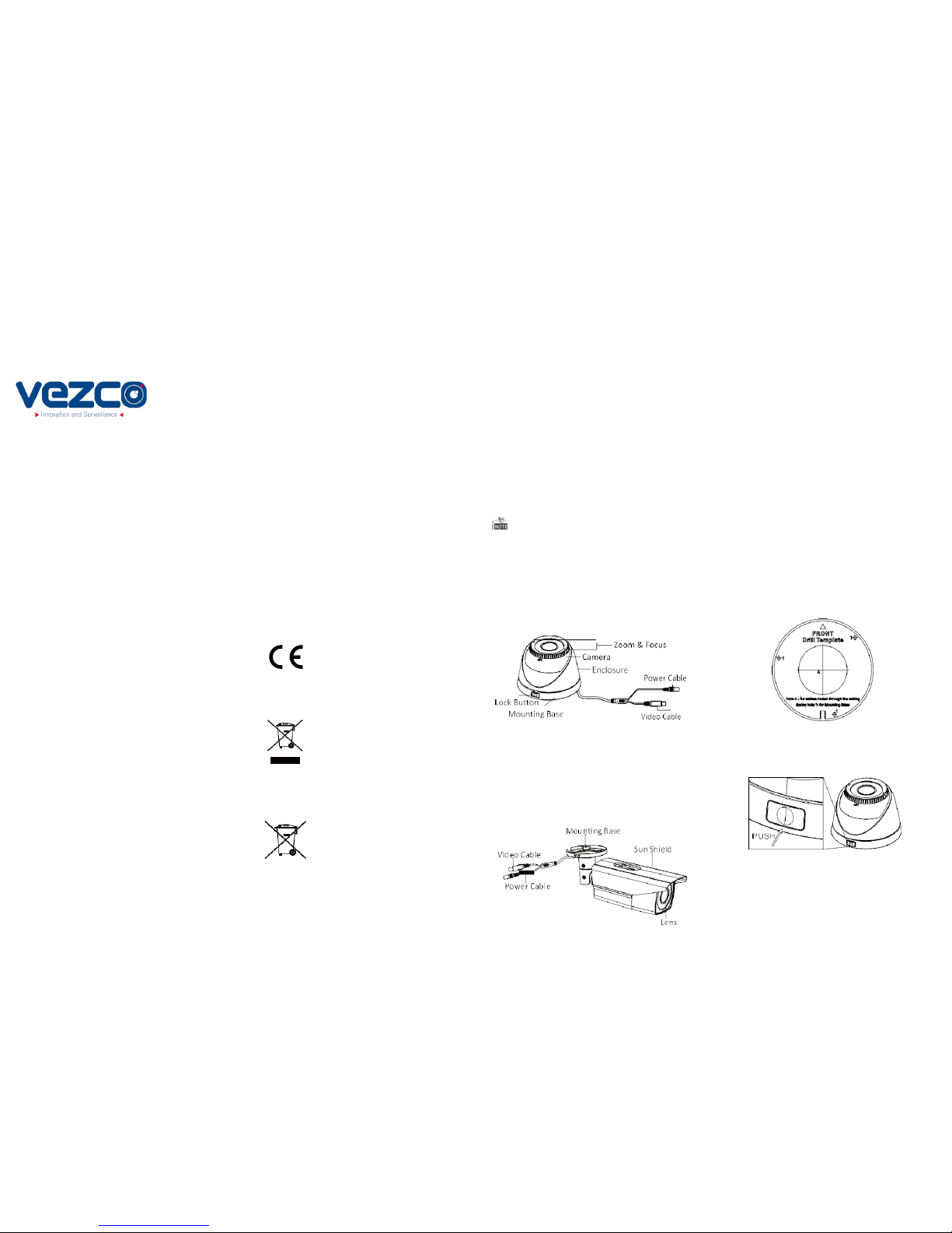
1.2 Overview
1.2.1 Overview of Type I Camera
2 Installation
Before you start:
•
Please make sure that the device in the package is
in good condition and all the assembly parts are
included.
•
Make sure that all the related equipment i
s
power-off during the installation.
•
Ch
eck the specification of the pr
oducts fo
r the
installation environment.
•
Check whether the
pow
er
supply
is matc
hed
with your power output to avoid damage.
•
Please make
sur
e the wall is str
ong enough to
withstand three times the weight of the camera
and the mounting.
•
If the wall is the cement wall, you need to insert
expansion screws before you install the camera.
If the wall is the wooden wall, you can use
self-tapping screw to secure the camera.
•
If
the pr
oduct does not function
properly,
please contact your dealer or the nearest
service center. Do not disassemble the camera
for repair or maintenance by yourself.
2.1 Installation of Type I Camera
Steps:
1. Drill t he screw holes and the cable ho le on t he
ceil ing a ccording to the s upplie d dril l templat e.
Thank you for purchasing our product. If there
are any questions, or requests, please do not
hesitate to contact the dealer.
This manual may contain several technical
incorrect places or printing errors, and the
content is subject to change without notice. The
updates will be added to the new version of this
manual. We will readily improve or update the
products or procedures described in the
manual.
This product and - if applic able - the
supp lied a ccesso ries too are mar ked
with "CE" and comply therefore with
the applicable harmonized European
standards listed under the Low Voltage Directive
2006/95/EC, the EMC Directive 2004/108/EC, the
RoHS Directive 2011/65/EU.
2012/19/EU (WEEE directive):
Products marked with this symbol
cannot be disposed of as unsorted
Figure 2-1 the Drill Template
Privacy Notice
Surveillance laws vary by jurisdiction. Check all
relevant laws in your jurisdiction before using this
product for surveillance purposes to ensure that
your use of this product conforms.
Please refer to the product specification for
camera parameters and functions.
www.vezcocctv.com
municipal waste in the European
Union. For proper recycling, return
this product to your local supplier
upon the purchase of equivalent new equipment, or
dispose of it at designated collection points. For more
information see: www.recyclethis.info.
2006/66/EC (battery directive):
This product contains a battery that
cannot be disposed of as unsorted
municipal waste in the European
Union.
See the product documentation for specific battery
information. The battery is marked with this symbol,
which may include lettering to indicate cadmium
(Cd), lead (Pb), or mercury (Hg).
For proper recycling, return the battery to your
supplier or to a designated collection point. For
more information see: www.recyclethis.info.
Figure 1-1 Overview of Type I Camera
1.2.2 Overview of Type
II
Camera
Figure 1-2 Overview of Type II Camera
2. Push the lock button to dis assemb le the camer a
from the mounting base.
Figure 2-2 Release the Lock Screw
3.Fix the mounting base to the ceiling.
4. Route the cables to the ca ble hol e and connec t
the corresponding cables.
5. Secure the came ra to the mountin g base by
supplied screws. Keep the word UP on the camera
being upright during the installation to make the
image showing normally.
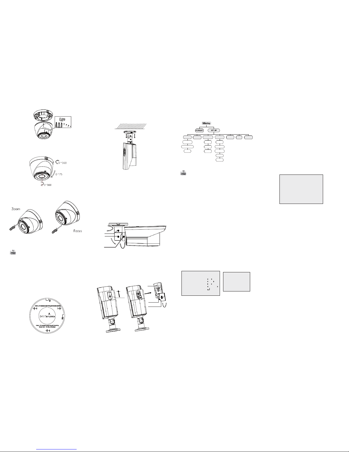
Figure 2-3 Secure the Camera
6. Adjust the camer a accor ding to t he figu re belo w
to get a n optimu m angl e.
Figure 2-4 Universal Adjustment
7. Use the s crewdri ver to a djust th e ZOOM s crew
and t he FOCUS screw until y ou get th e optimu m
imag e.
Figure 2-5 Zoom and Focus Adjustment
2.2 Installation of Type II Camera
Both wall mounting and ceiling mounting are
suitable for type II bullet camera. Ceiling mounting
3. Route the cables to the ca ble hol e and connec t
the c orresp onding cable s.
4. Fix the c amera to the ceil ing wi th the sup plied
scre ws.
Figure 2-7 Fix the Camera to the Ceiling
5. Adju st the s urveil lance a ngle.
1). Loosen No.1 adjusting screw to adjust the pan
position (0° ~ 360°).
2).Tighten No.1 adjusting screw.
3). Loosen No.2 adjusting screw to adjust the
tilting position (0° ~ 90°).
4).Tighten No.2 adjusting screw.
5). Loosen No.3 adjusting screw to adjust the
rotation position (0° ~ 360° ).
6).Tighten No.3 adjusting screw.
0~360
1
2
0~90
3
0~360
Figure 2-8 3-axis Adjustment
3 Menu Operation
Figure 3-1 Main Menu
With a coaxial camera controller (purchase
separately) or calling the preset No.95 you can
select the menu and adjust the camera parameters.
3.1 FORM AT
You can set the format as PAL/NTSC.
3.2 SET UP
Move the cursor to SET UP, and press menu button to
enter the SET UP sub menu.
3.2.1 AE
Move the cursor to AE, and you can adjust the
image brightness by the BRIGHTNESS, EXPOSURE
MODE, and AGC.
Brightness:
Brightness refers to the brightness of the image.
Exposure Mode:
Move the cursor to Exposure Mode, you can select
the exposure mode between Globe and BLC.
When BLC is selected as the exposure mode, the level
of BLC mode can be adjusted, as shown in the
AWB: white balance is being adjusted
automatically.
MWB: Set the R GAIN/B GAIN value from 1 to 10.
As shown in Figure 3-3.
3.2.3 DAY & NIGH T
Move the cursor to DAY & NIGHT, and select
COLOR, B/W, or SMART as the DAY & NIGHT mode.
COLOR: The image is colored in day mode all the
time.
B/W: The image is black & white all the time, and
the IR LED turns on in the low-light conditions.
SMART: Select to turn on/off the INFRARED_LAMP
and to set the Smart IR level from 1to 16.
As shown in Figure 3-4.
Figure 3-4 DAY/NIGHT
3.2.4 VI DEO SET TIN G
Cont rast:
Contrast enhances the difference in color and light
between parts of an image.
You can set the value from 1 to 10.
Sharpness:
Sharpness determines the amount of
detail that an imaging system can reproduce.
You can set the value from 1 to 10.
Saturation:
You can set the saturation level of the image. The
will be taken as an example in the section. And you
can take steps of ceiling mounting as a reference
if wall mounting is adopted.
Steps:
1.Drill the screw holes and the cable hole in the
ceiling according to the supplied drill template.
2.Hammer the supplied plastic expansion bolt into
the screw holes.
6. Push th e focus & zoom adj ustment cover u pward
to move it aside.
7. Use the cover as a screwdr iver to adjust t he ZOOM
scre w and the FOCUS screw u ntil yo u get the
optimum image.
Figure 3-2.
Figure 3-2 EXPOSURE
AGC:
Figure 3-3 WB
value is from 0 to 10.
DNR:
DNR decreases the noise effect, especially in low
light conditions and delivers more accurate and
sharp image quality. You can set the value from
0 to 7.
Mirror:
You can set the Mirror status as H, V, HV, or OFF.
3.2.5 Reset
Reset all the settings to the default.
Figure 2-6 Drill Template
Figure 2-9 Zoom and Focus Adjustment
AGC optimizes the clarity of image in poor light
scene. AGC level can be set as OFF, LOW, MIDDLE
and HIGH.
3.2.2 WB
Move the cursor to WB, and you can set White
Balance mode as AWB and MWB in this menu.
3.2.6 EX IT
Exit and Save & exit are selectable.
3.2.7 SA VE/E XIT
Move the cursor to SAVE & Exit, and press OK to
save the settings and exit the menu.
AE WB DAY/NIGHT
VIDEO
SETTING
RESET EXIT SAVE/EXIT
BRIGHTNESS
MODE
CONTRAST
EXPOSURE MODE INFRARED SHARPNESS AGC SMART IR
SATURATION
DNR
MIRROR
DAY/NIGHT
MODE SMART
INFRARED OFF
SMART IR 0-|--5
RETURN
‘
Focus Cover
Zoom
Cover
0~360
EXPOSURE
1. BRIGHTNESS 5
2. EXPOSURE MODE BLC
LEVEL 5
3. AGC MIDDLE
4. RETURN
WB
MODE
R GIAN
B GAIN
RETURN
MWB
1-|--10
1-|--10
‘
 Loading...