

Page 1

Video Intercom Door
Station
Quick Start Guide
Page 2

Video Intercom Door Station·Quick Start Guide
ii
Quick Start Guide
This quick start guide is intended for users of the D-series door stations.
Disclaimer
REGARDING TO THE PRODUCT WITH INTERNET ACCESS, THE USE OF PRODUCT SHALL BE WHOLLY
AT YOUR OWN RISKS. OUR COMPANY SHALL NOT TAKE ANY RESPONSIBILITES FOR ABNORMAL
OPERATION, PRIVACY LEAKAGE OR OTHER DAMAGES RESULTING FROM CYBER ATTACK, HACKER
ATTACK, VIRUS INSPECTION, OR OTHER INTERNET SECURITY RISKS; HOWEVER, OUR COMPANY
WILL PROVIDE TIMELY TECHNICAL SUPPORT IF REQUIRED.
SURVEILLANCE LAWS VARY BY JURISDICTION. PLEASE CHECK ALL RELEVANT LAWS IN YOUR
JURISDICTION BEFORE USING THIS PRODUCT IN ORDER TO ENSURE THAT YOUR USE CONFORMS
THE APPLICABLE LAW. OUR COMPANY SHALL NOT BE LIABLE IN THE EVENT THAT THIS PRODUCT IS
USED WITH ILLEGITIMATE PURPOSES.
IN THE EVENT OF ANY CONFLICTS BETWEEN THIS MANUAL AND THE APPLICABLE LAW, THE LATER
PREVAILS.
Support
Should you have any questions, please do not hesitate to contact your local dealer.
Page 3
Video Intercom Door Station·Quick Start Guide
iii
Regulatory Information
FCC Information
Please take attention that changes or modification not expressly approved by the party
responsible for compliance could void the user’s authority to operate the equipment.
FCC compliance: This equipment has been tested and found to comply with the limits
for a Class B digital device, pursuant to part 15 of the FCC Rules. These limits are
designed to provide reasonable protection against harmful interference in a residential
installation. This equipment generates, uses and can radiate radio frequency energy and,
if not installed and used in accordance with the instructions, may cause harmful
interference to radio communications. However, there is no guarantee that interference
will not occur in a particular installation. If this equipment does cause harmful
interference to radio or television reception, which can be determined by turning the
equipment off and on, the user is encouraged to try to correct the interference by one
or more of the following measures:
—Reorient or relocate the receiving antenna.
—Increase the separation between the equipment and receiver.
—Connect the equipment into an outlet on a circuit different from that to which the
receiver is connected.
—Consult the dealer or an experienced radio/TV technician for help.
FCC Conditions
This device complies with part 15 of the FCC Rules. Operation is subject to the following
two conditions:
1. This device may not cause harmful interference.
2. This device must accept any interference received, including interference that may
cause undesired operation.
EU Conformity Statement
This product and - if applicable - the supplied accessories too are
marked with "CE" and comply therefore with the applicable
harmonized European standards listed under the EMC Directive
2014/30/EU, the RoHS Directive 2011/65/EU.
2012/19/EU (WEEE directive): Products marked with this symbol
cannot be disposed of as unsorted municipal waste in the European
Union. For proper recycling, return this product to your local supplier
upon the purchase of equivalent new equipment, or dispose of it at
designated collection points. For more information see:
www.recyclethis.info
Page 4

Video Intercom Door Station·Quick Start Guide
iv
2006/66/EC (battery directive): This product contains a battery that
cannot be disposed of as unsorted municipal waste in the European
Union. See the product documentation for specific battery information.
The battery is marked with this symbol, which may include lettering to
indicate cadmium (Cd), lead (Pb), or mercury (Hg). For proper recycling,
return the battery to your supplier or to a designated collection point.
For more information see: www.recyclethis.info
Industry Canada ICES-003 Compliance
This device meets the CAN ICES-3 (B)/NMB-3(B) standards requirements.
Page 5
Video Intercom Door Station·Quick Start Guide
v
Safety Instruction
These instructions are intended to ensure that user can use the product correctly to
avoid danger or property loss.
The precaution measure is divided into Warnings and Cautions:
Warnings: Neglecting any of the warnings may cause serious injury or death.
Cautions: Neglecting any of the cautions may cause injury or equipment damage.
Warnings Follow
Cautions Follow these
these safeguards to
precautions to prevent
prevent serious
potential injury or
injury or death.
material damage.
Warnings
The working temperature of the device is from -40º C to 60º C.
All the electronic operation should be strictly compliance with the electrical safety
regulations, fire prevention regulations and other related regulations in your local
region.
Please use the power adapter, which is provided by normal company. The power
consumption cannot be less than the required value.
Do not connect several devices to one power adapter as adapter overload may cause
over-heat or fire hazard.
Please make sure that the power has been disconnected before you wire, install or
dismantle the device.
When the product is installed on wall or ceiling, the device shall be firmly fixed.
If smoke, odors or noise rise from the device, turn off the power at once and unplug
the power cable, and then please contact the service center.
If the product does not work properly, please contact your dealer or the nearest
service center. Never attempt to disassemble the device yourself. (We shall not
assume any responsibility for problems caused by unauthorized repair or
maintenance.)
The power supply must conform to LPS. The recommended adaptor models and
manufacturers are shown as below. Use the attached adaptor, and do not change the
adaptor randomly.
Page 6
Video Intercom Door Station·Quick Start Guide
vi
Cautions
Do not drop the device or subject it to physical shock, and do not expose it to high
electromagnetism radiation. Avoid the equipment installation on vibrations surface or
places subject to shock (ignorance can cause equipment damage).
Do not place the device in extremely hot (refer to the specification of the device for
the detailed operating temperature), cold, dusty or damp locations, and do not
expose it to high electromagnetic radiation.
The device cover for indoor use shall be kept from rain and moisture.
Exposing the equipment to direct sun light, low ventilation or heat source such as
heater or radiator is forbidden (ignorance can cause fire danger).
Do not aim the device at the sun or extra bright places. A blooming or smear may
occur otherwise (which is not a malfunction however), and affecting the endurance of
sensor at the same time.
Please use the provided glove when open up the device cover, avoid direct contact
with the device cover, because the acidic sweat of the fingers may erode the surface
coating of the device cover.
Please use a soft and dry cloth when clean inside and outside surfaces of the device
cover, do not use alkaline detergents.
Please keep all wrappers after unpack them for future use. In case of any failure
occurred, you need to return the device to the factory with the original wrapper.
Transportation without the original wrapper may result in damage on the device and
lead to additional costs.
Improper use or replacement of the battery may result in hazard of explosion.
Replace with the same or equivalent type only. Dispose of used batteries according to
the instructions provided by the battery manufacturer.
Page 7

Video Intercom Door Station·Quick Start Guide
vii
Table of Contents
1 Appearance ..............................................................................................1
1.1 Appearance of Door Station .................................................................................. 1
2 Terminal and Wiring .................................................................................3
2.1 Terminal Description ............................................................................................. 3
2.2 Wiring Description ................................................................................................ 6
2.2.1 Door Lock Wiring ............................................................................................ 6
2.2.2 Door Magnetic Wiring .................................................................................... 7
2.2.3 Exit Button Wiring .......................................................................................... 7
2.2.4 External Card Reader Wiring ........................................................................... 8
2.2.5 External Elevator Controller Wiring ................................................................ 9
2.2.6 Alarm Device Input Wiring ........................................................................... 10
2.2.7 Alarm Device Output Wiring ......................................................................... 10
3 Installation ............................................................................................. 11
3.1 Installation of Door Station ................................................................................ 11
3.1.1 Gang Box ..................................................................................................... 11
3.1.2 Wall Mounting with Gang Box ................................................................... 12
4 Before You Start ..................................................................................... 14
5 Local Operation ............................................................................................ 15
5.1 Keys Description ................................................................................................. 15
5.2 Activating Device ................................................................................................ 15
5.3 Editing Network Parameters ...................................................................................... 17
5.4 Changing Password ..................................................................................................... 18
5.5 Calling Resident ........................................................................................................... 20
5.6 Unlocking Door .................................................................................................... 21
6 Remote Operation via Batch Configuration Software ................................. 22
6.1 Activating Device Remotely ....................................................................................... 22
6.2 Editing Network Parameters ...................................................................................... 23
6.3 Adding Device ..................................................................................................... 24
6.3.1 Adding Online Device ................................................................................... 24
6.3.2 Adding by IP Address ............................................................................................... 25
Appendix .................................................................................................... 27
Installation Notice ........................................................................................................ 27
Wiring Cables ................................................................................................................ 27
Page 8
Video Intercom Door Station·Quick Start Guide
1
1 Appearance
1.1 Appearance of Door Station
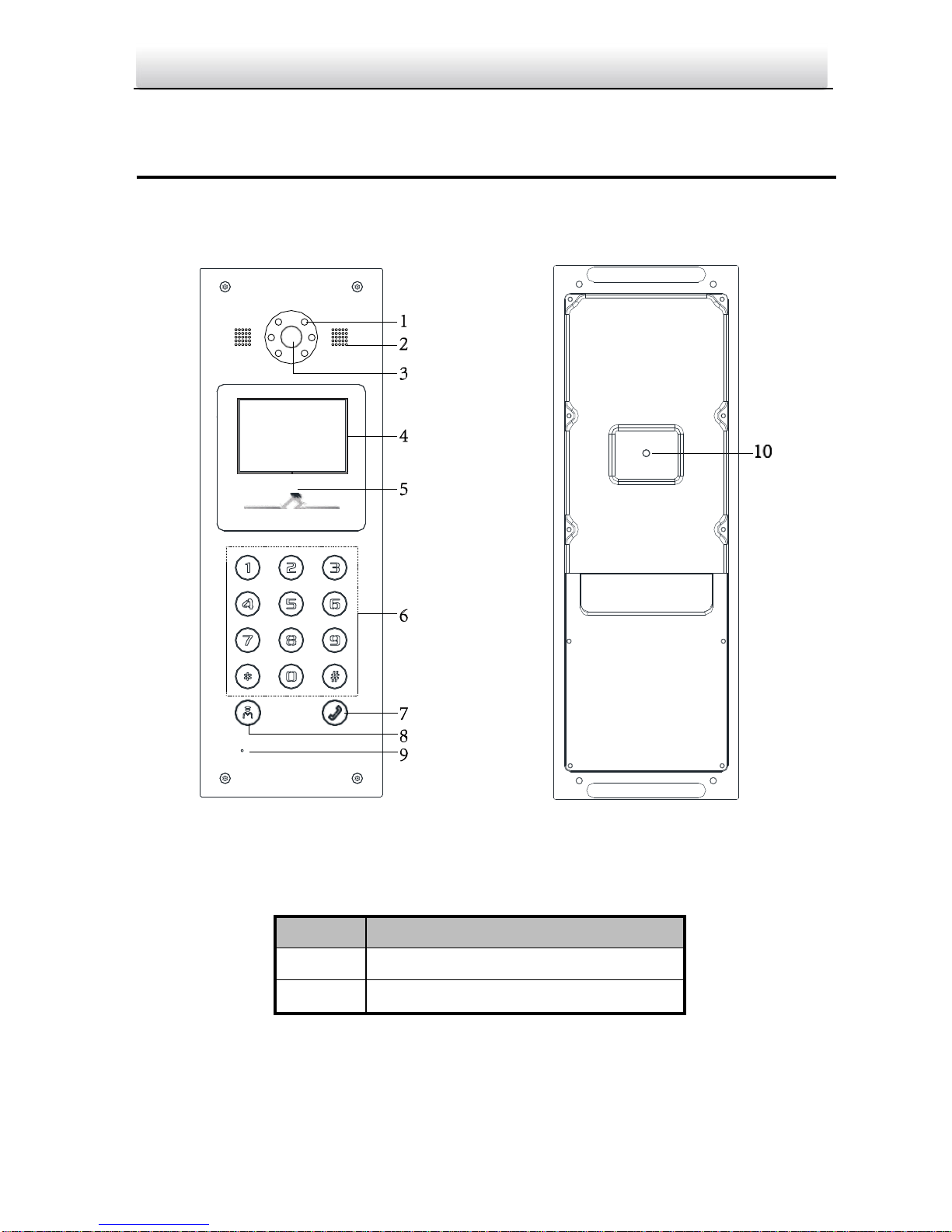
Figure 1-1 Front View Figure 1-2 Rear View
Table 1-1 Descriptions Keys
No.
Description
1
Low Illumination Supplement Light
2
Built-in Camera
Page 9
Video Intercom Door Station·Quick Start Guide
2
No.
Description
3
Loudspeaker
4
LCD Display Screen
5
Card Induction Area
6
Keypad
7
Call Button
8
Call Center Key
9
Microphone
10
TAMPER
Page 10
Video Intercom Door Station·Quick Start Guide
3
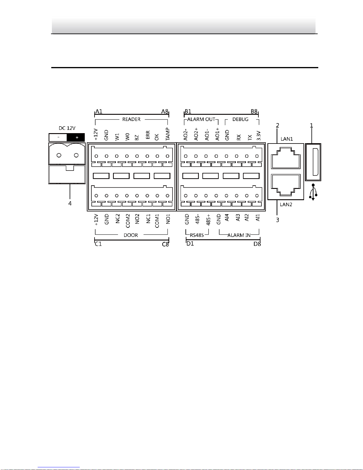
2 Terminal and Wiring
2.1 Terminal Description
Figure 2-1 Terminals and Interfaces
Page 11
Video Intercom Door Station·Quick Start Guide
4
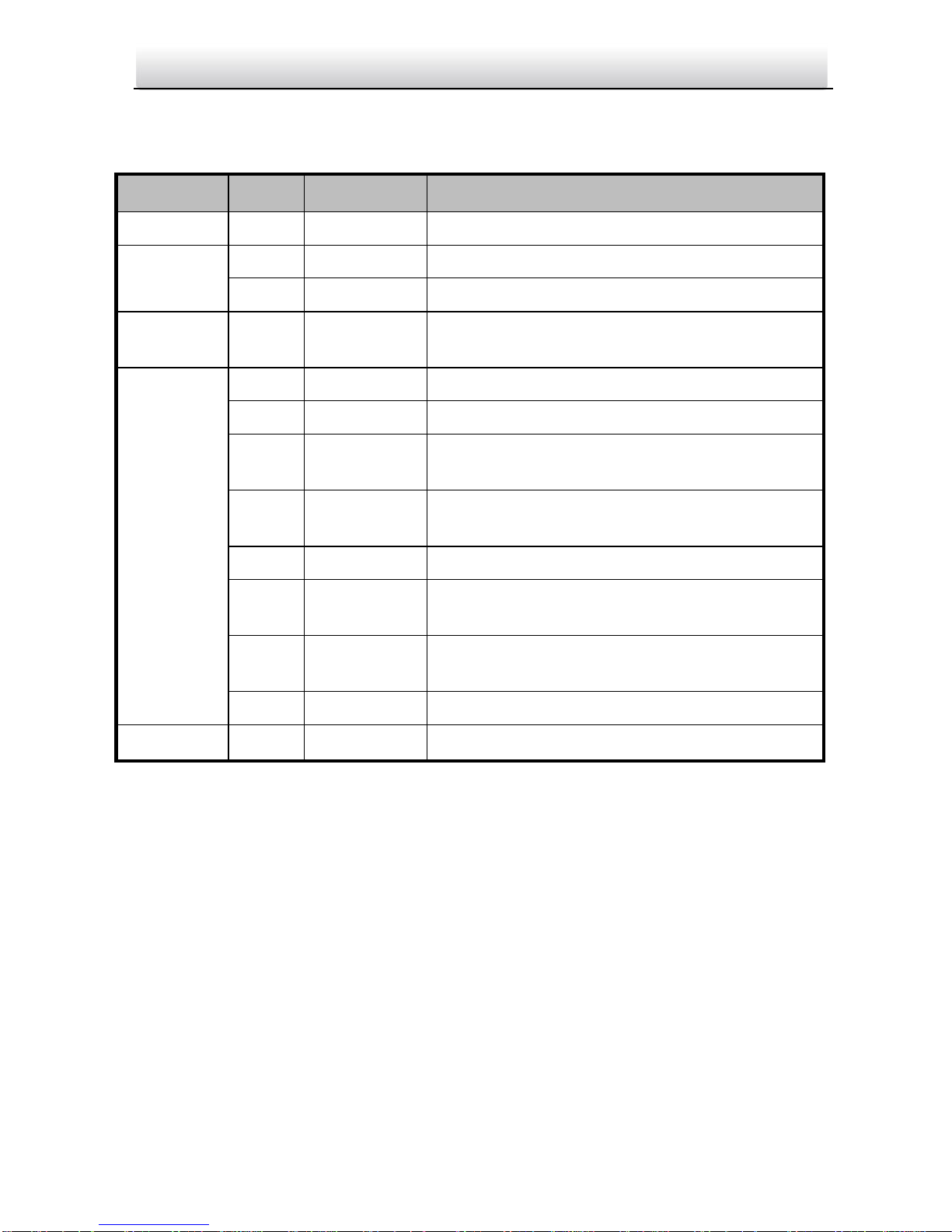
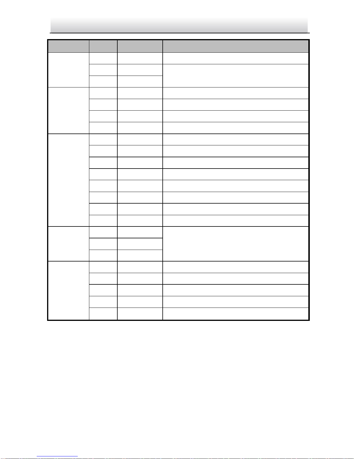
Table 2-2 Descriptions of Terminals and Interfaces
Name
No.
Interface
Description
USB 1 USB
USB Interface
LAN
2
LAN1
Network Interface
3
LAN2
Reserved
Power
Supply
4
DC 12V
DC 12V Power Supply Input
READER
A1
12V
Power Supply Output
A2
GND
Grounding
A3
W1
Data Input Interface Wiegand Card Reader:
Data1
A4
W0
Data Input Interface Wiegand Card Reader:
Data0
A5
BZ
Card Reader Buzzer Output
A6
ERR
Card Reader Indicator Output (Invalid Card
Output)
A7
OK
Card Reader Indicator Output (Valid Card
Output)
A8
TAMP
Tamper-proof Input of Wiegand Card Reader
ALARM
B1
AO2-
Alarm Relay Output 2
Page 12
Video Intercom Door Station·Quick Start Guide
5
Name
No.
Interface
Description
OUT
B2
AO2+
B3
AO1-
Alarm Relay Output 1
B4
AO1+
DEBUG
B5
GND
Grounding
B6
RX
Serial Port Debugging/Receive data
B7
TX
Serial Port Debugging/Send data
B8
3.3V
Serial Port Debugging/Power Supply
DOOR
C1
12V
Power Supply Output
C2
GND
Grounding
C3
NC2
Door Lock Relay Output (NC)
C4
COM2
Grounding Signal
C5
NO2
Door Lock Relay Output (NO)
C6
NC1
Door Lock Relay Output (NC)
C7
COM1
Grounding Signal
C8
NO1
Door Lock Relay Output (NC)
RS485
D1
GND
RS-485 Communication Interfaces
D2
485-
D3
485+
ALARM IN
D4
GND
Grounding Signal
D5
AI4
Alarm Input 4
D6
AI3
Alarm Input 3
D7
AI2
Alarm Input 2
D8
AI1
Alarm Input 1
Page 13
Video Intercom Door Station·Quick Start Guide
6
2.2 Wiring Description
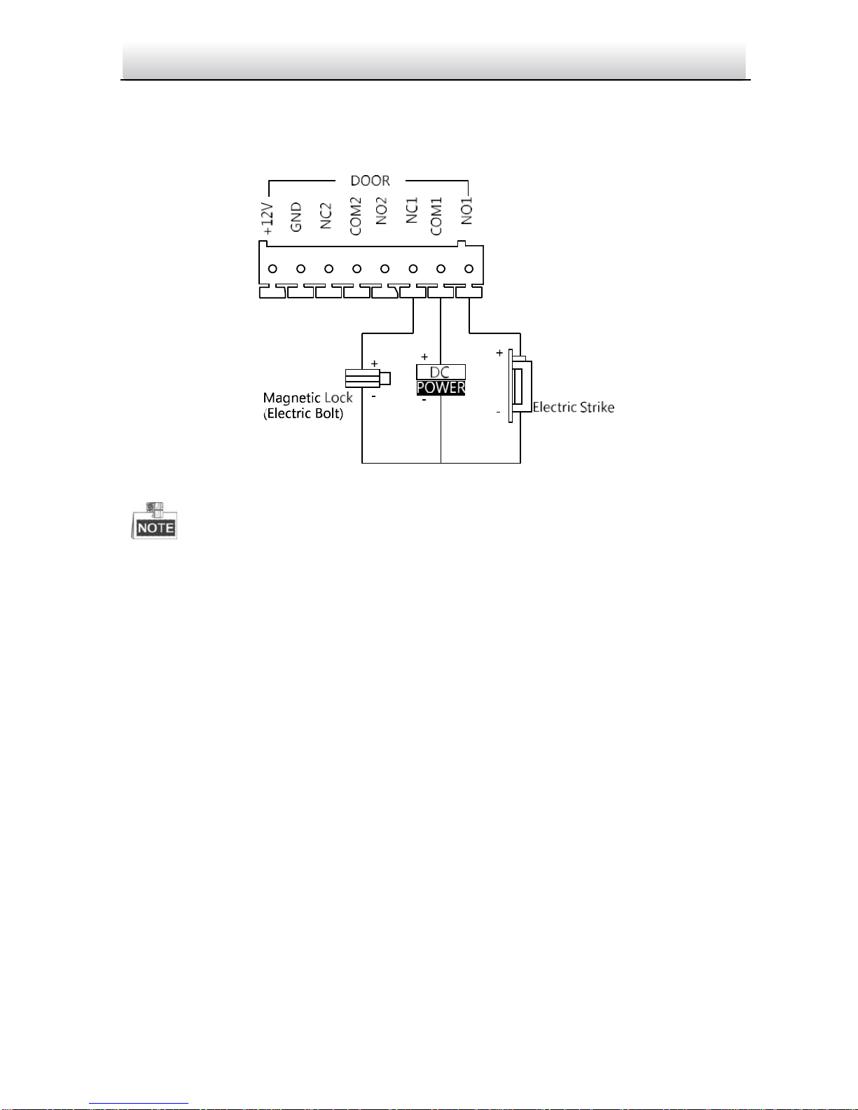
2.2.1 Door Lock Wiring
Figure 2-2 Door Lock Wiring
Terminal NC1/COM1 is set as default for accessing magnetic lock/electric bolt;
terminal NO1/COM1 is set as default for accessing electric strike.
To connect electric lock in terminal NO2/COM2/NC2, it is required to set the output of
terminal NO2/COM2/NC2 to be electric lock with Batch Configuration Tool or
VEZPRO.
Page 14
Video Intercom Door Station·Quick Start Guide
7
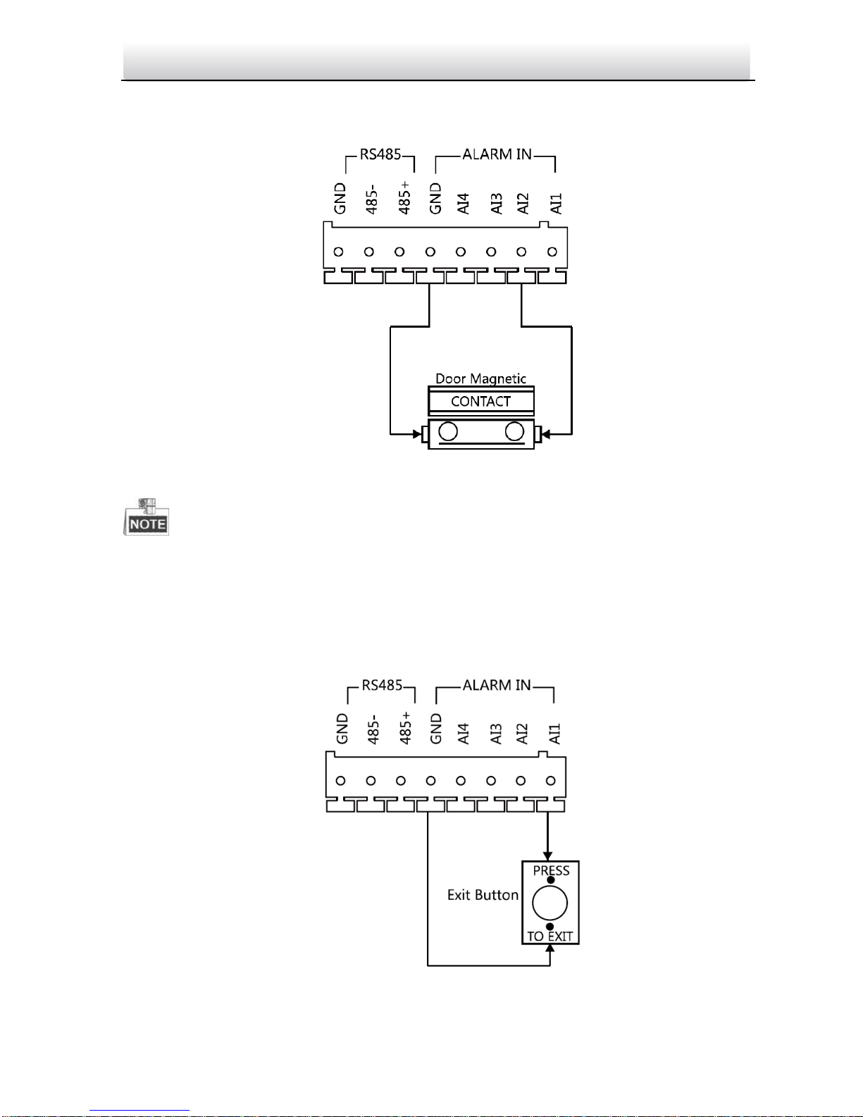
2.2.2 Door Magnetic Wiring
Door Magnetic Wiring
Figure 2-3 Door Magnetic Wiring
To connect the door magnetic, it is required to set the output of terminal AI2 to be door
magnetic with Batch Configuration Tool or VEZPRO.
2.2.3 Exit Button Wiring
Exit Button Wiring
Figure 2-4 Exit Button Wiring
Page 15
Video Intercom Door Station·Quick Start Guide
8
Terminal S1 is set as default for connecting exit button.
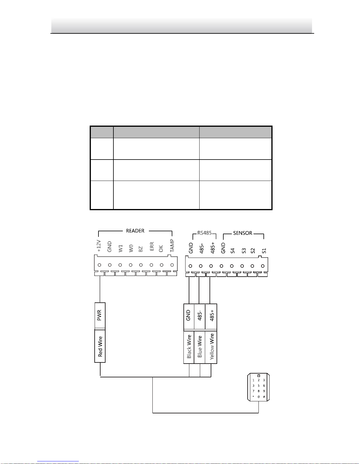
2.2.4 External Card Reader Wiring
Please set the DIP switch first before connecting the card reader.
If the DIP switch should be configured when the card reader is power-on, please
reboot the card reader after configuring the DIP switch.
The DIP switch description is shown in the following table:
No.
Description
How to Configure
1-4
Set the RS-485 address
ON: 1
OFF: 0
6
Select Wiegand protocol
or RS-485 protocol
ON: Wiegand
OFF: RS-485
7
Set the Wiegand protocol
(It is invalid when setting
OFF in 6.)
ON: Wiegand 26
OFF: Wiegand 34
RS-485 Card Reader Wiring
Figure 2-5 RS-485 Card Reader Wiring
Page 16
Video Intercom Door Station·Quick Start Guide
9
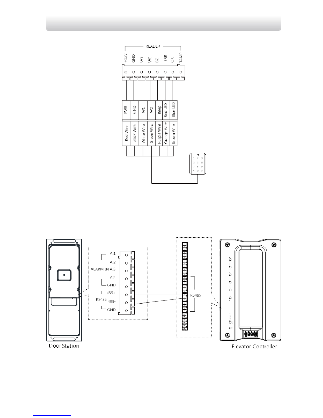
Wiegand Card Reader Wiring
Figure 2-11 External Card Reader Wiring
2.2.5 External Elevator Controller Wiring
You can connect the door station to the elevator controller via RS-485 interface.
There are 4 groups of RS-485 interfaces on the elevator controller: group A, group B,
Group C, and Group D. Group C is used to connect to the door station.
Figure 2-6 External Elevator Controller Wiring
Page 17
Video Intercom Door Station·Quick Start Guide
10
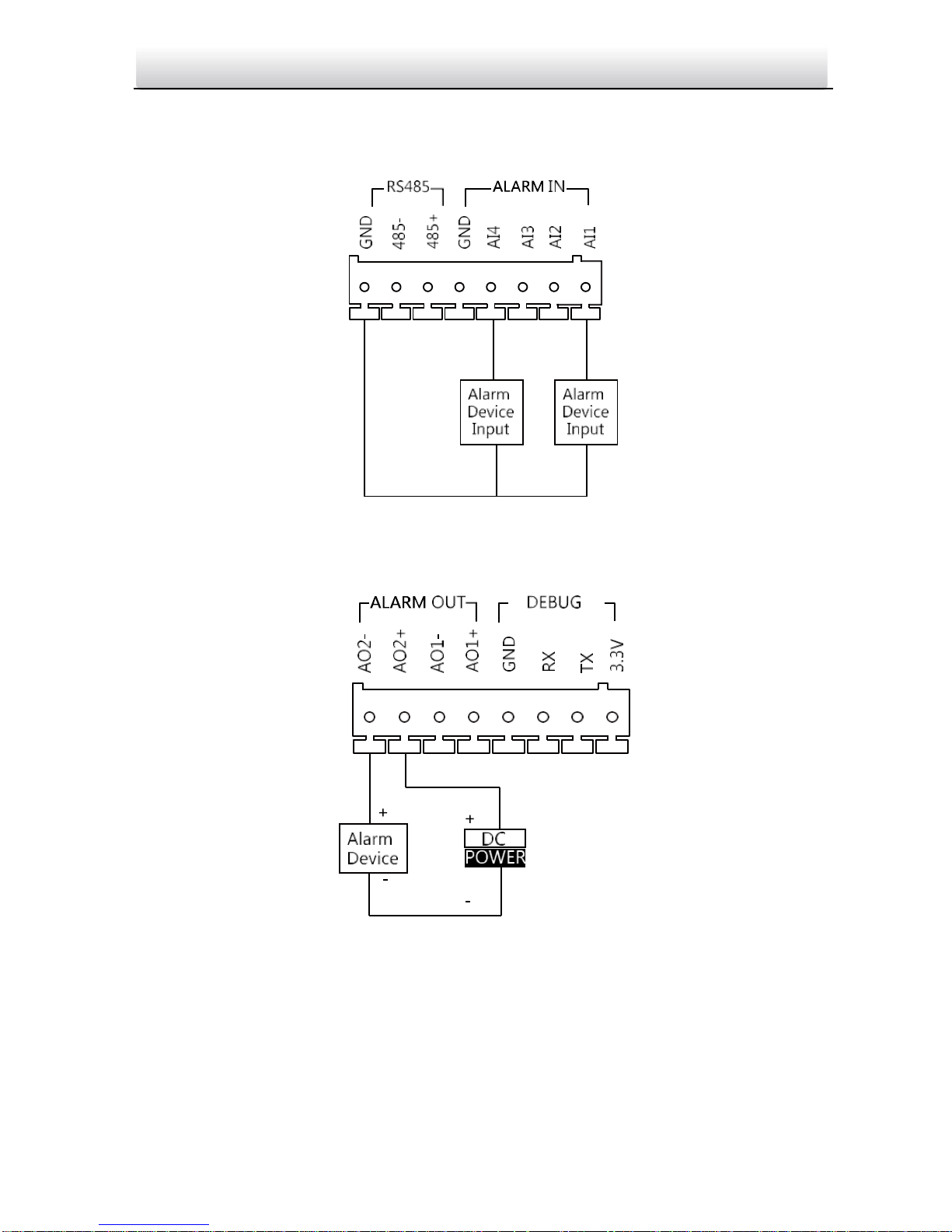
2.2.6 Alarm Device Input Wiring
Alarm Device Input Wiring
Figure 2-7 Alarm Device Input Wiring Alarm Device Output Wiring
Alarm Device Output Wiring
Figure 2-8 Alarm Device Output Wiring
Page 18
Video Intercom Door Station·Quick Start Guide
11
3 Installation
Before you start:
Make sure the device in the package is in good condition and all the assembly
parts are included.
The power supply the door station supports is 12 VDC. Please make sure your power
supply matches your door station.
Make sure all the related equipment is power-off during the installation.
Check the product specification for the installation environment.
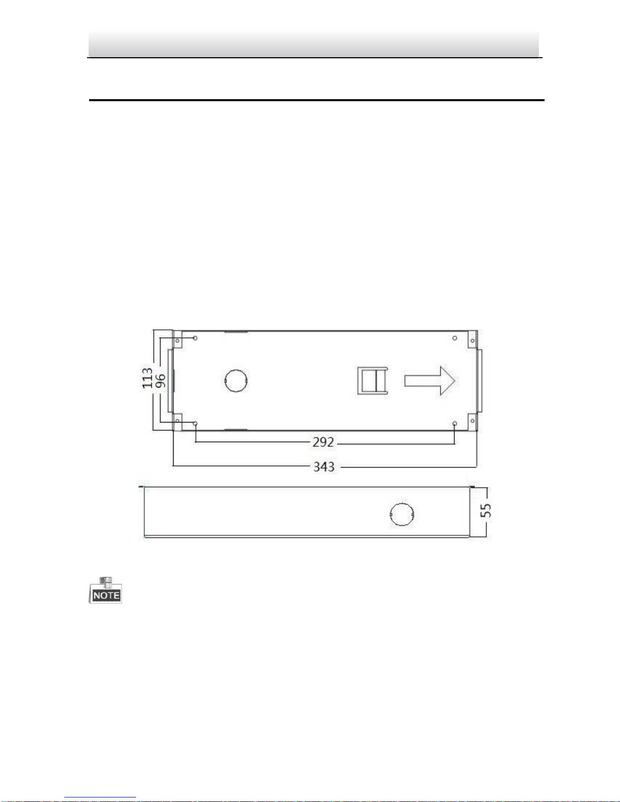
3.1 Installation
3.1.1 Gang Box
Figure 3-1 Front and Side View
The dimension of gang box door station is: 343(length)×113(width)× 55(depth)
mm.
The dimensions above are for reference only. The actual size can be slightly different
from the theoretical dimension.
Page 19
Video Intercom Door Station·Quick Start Guide
12
3.1.2 Wall Mounting with Gang Box
Steps:
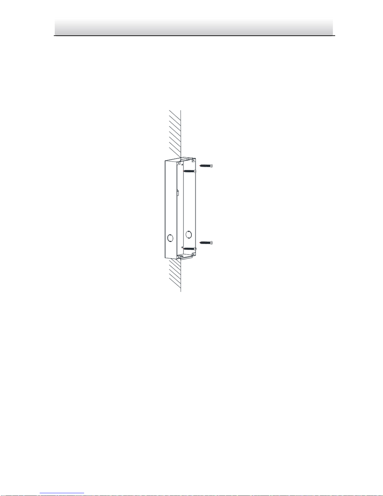
1. Chisel a hole in the wall for inserting the gang box. The size of the hole should be
larger than that of the gang box. The suggested size of hole is 343.5 (length) × 113.5
(width) × 55.5 (depth) mm.
2. Insert the gang box into the hole and fix it with 4 PA4 screws.
Screw
Screw
Figure 3-2 Insert the Gang Box into the Wall
3. Make sure the edges of the gang box align to the wall.
4. Route the cables of the door station through the cable hole.
Page 20
Video Intercom Door Station·Quick Start Guide
13
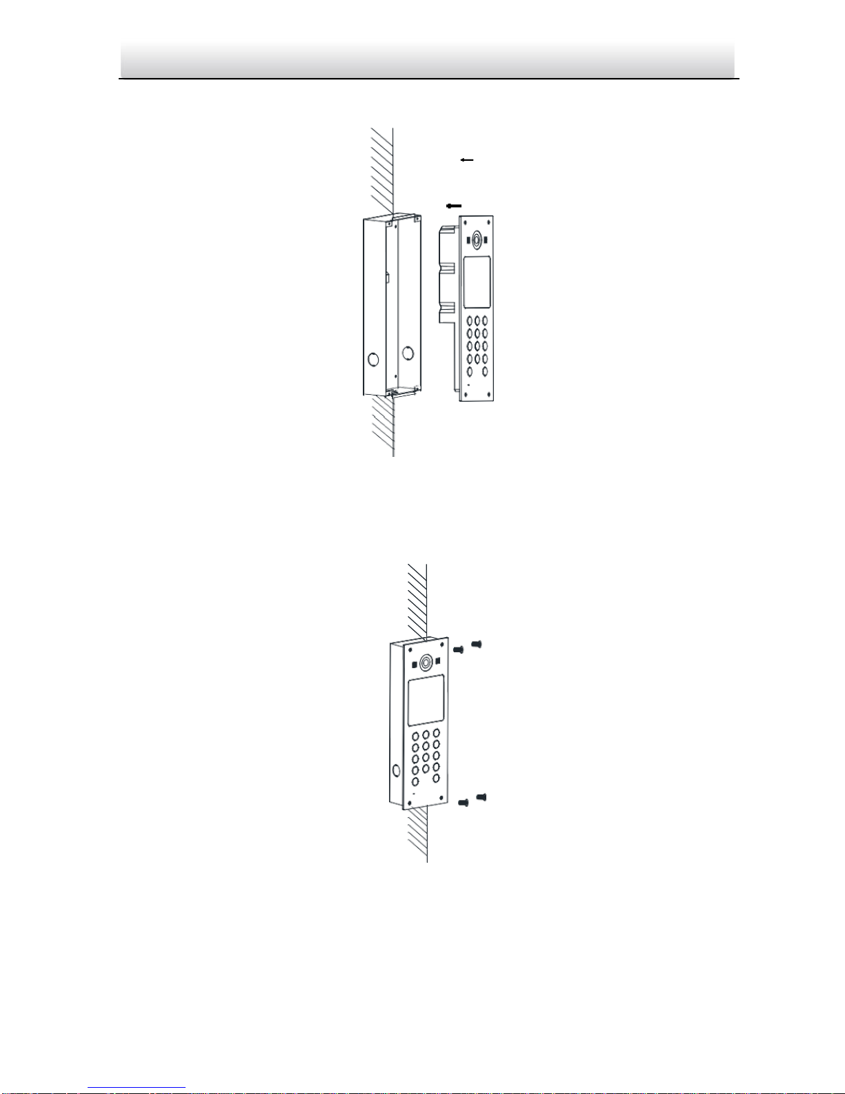
5. Put the door station into the gang box.
Figure 3-3 Install the Door Station
6. Fix the door station to the gang box with 4 crews.
Figure 3-4 Tighten the Screws of Device
Page 21
Video Intercom Door Station·Quick Start Guide
14
4 Before You Start
For the first time use of the device, you are required to activate the device and set the
activation password. You can activate the device via internet with Batch Configuration
Tool, or with VEZPRO client software.
To activate the device with Batch Configuration Tool or VEZPRO, refer to
6.1 Activating Device Remotely.
To activate the device locally, refer to 5.2 Activating Device.
To configure the key parameters of device on the user interface of door
station, you are required to input the admin password. Here the admin password refers
to the configuration password.
The default admin password (configuration password) is 888999.
You can set the login password of the device by yourself.
You must change the default credential to protect against unauthorized access to the
product. Please refer to 5.4 Changing Password.
Page 22
Video Intercom Door Station·Quick Start Guide
15
5 Local Operation
5.1 Keys Description
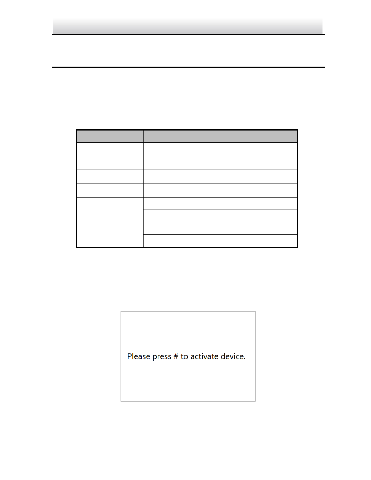
Key descriptions of door stations are illustrated in Table 5-1.
Table 5-1 Key Descriptions 1
Key
Description
Numeric Key 2
▲
Numeric Key 4
▼
Numeric Key 6
◄
Numeric Key 8
►
#
Call Key (When calling residents or center)
Confirm
*
Return
Delete
5.2 Activating Device
You cannot use the door station until you activate it.
Steps:
1. Power on the door station to enter the activation interface automatically.
Figure 5-1 Activate the Device (Option 1)
2. Press the # key.
Page 23
Video Intercom Door Station·Quick Start Guide
16
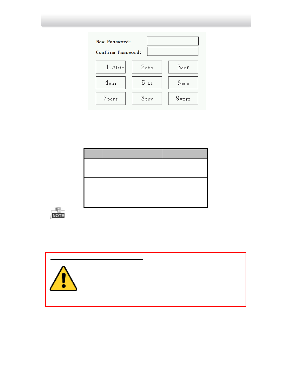
Figure 5-2 Set Password
3. Enter a new password, and confirm the password.
The character description for each numeric key is shown in Table 5-2.
Table 5-2 Character Description
When entering the password, taking the numeric key 2 as example, press the
numeric key 2 once, the text field shows "2", and press it again, the text field shows
"a", and press it again, the text field shows "b", and so on.
4. Press the # key to complete the activation.
Key
Description
Key
Description
1
1,.?!*#-
6
6mnoMNO
2
2abcABC
7
7pqrsPQRS
3
3defDEF
8
8tuvTUV
4
4ghiGHI
9
9wxyzWXYZ
5
5jklJKL 0 0
STRONG PASSWORD RECOMMENDED– We highly recommend you create a
strong password of your own choosing (Using a minimum of 8
characters, including at least three of the following categories:
upper case letters, lower case letters, numbers, and special
characters.) in order to increase the security of your product. And
we recommend you reset your password regularly, especially in the
high security system, resetting the password monthly or weekly can better
protect your product.
Page 24
Video Intercom Door Station·Quick Start Guide
17
5.3 Editing Network Parameters
Purpose:
Network connection is mandatory for the use of door station.
Steps:
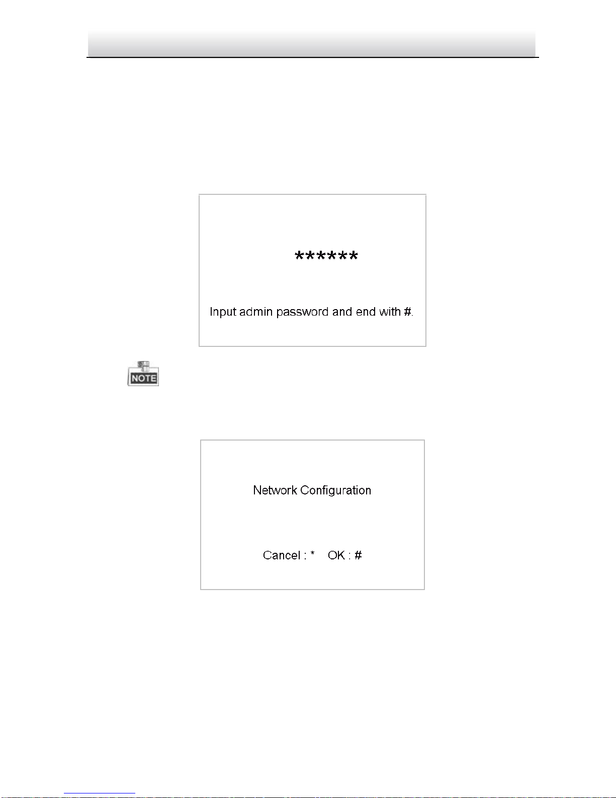
1. Go to the configuration mode.
1) Hold down the * key and the # key for 2s to enter the admin password interface.
2) Enter the admin password, and press the # key.
Figure 5-3 Admin Password Interface
The default admin password is 888999.
2. Enter the network parameters settings interface.
1) Press the numeric keys 4 and 6 to switch to the network configuration interface
Figure 5-4 Network Configuration Interface
2) Press the # key to enter the network parameters settings interface.
Page 25
Video Intercom Door Station·Quick Start Guide
18
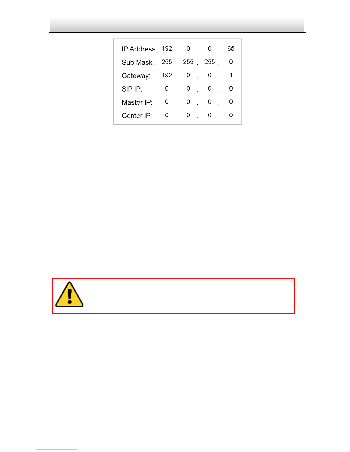
Figure 5-5 Network Parameters Settings Interface
3. Edit network parameters.
1) Move the cursor to parameters to be configured.
2) Press the # key and the * key to enter and exit the editing mode.
4. Press the * key to exit the network configuration interface after accomplishing
network parameters settings.
5.4 Changing Password
Purpose:
2 kinds of password are available when using the door station: configuration password
(admin password) and card activation password.
Configuration Password: It is necessary when you want to configure parameters of the
door station, such as IP parameters, door station No., system type, and so on.
Card Activation Password: It is necessary when you want to issue cards via password.
Steps:
1. Go to the configuration mode.
1) Hold down the * key and the # key for 2s to enter the admin password interface.
2) Enter the admin password, and press the # key.
The default configuration password is 888999. We recommend you
reset your password regularly, especially in the high security system,
resetting the password monthly or weekly can better protect your
product.
Page 26
Video Intercom Door Station·Quick Start Guide
19
Figure 5-6 Admin Password Interface
The default admin password is 888999.
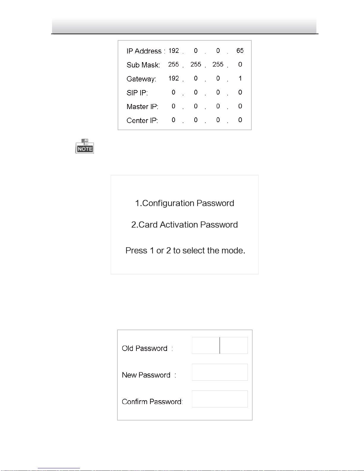
2. Press the numeric keys 4 and 6 to switch to the password settings interface.
Figure 5-7 Password Settings Interface
Changing Configuration Password
Steps:
1. On the password settings interface, press the numeric key 1 to enter the configuration
password changing interface.
Page 27
20
Video Intercom Door Station·Quick Start Guide
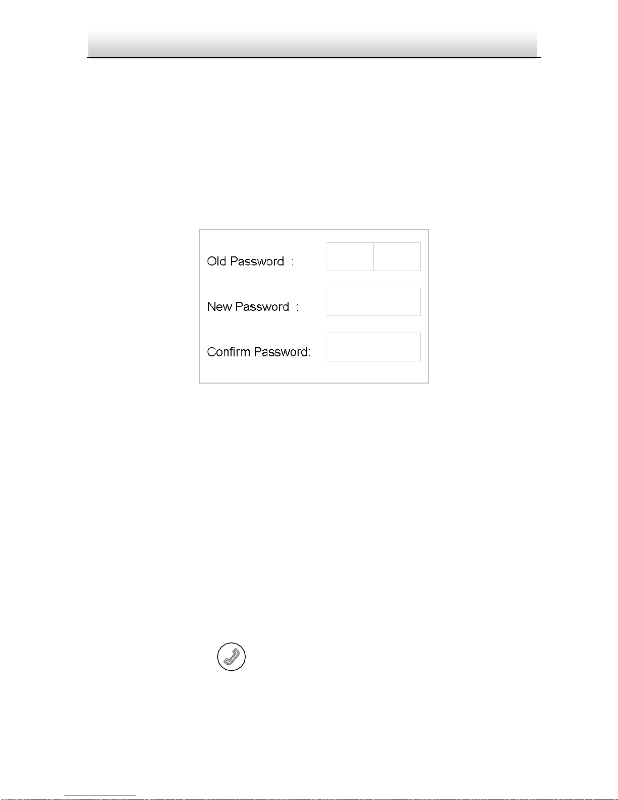
Figure 5-8 Configuration Password Changing Interface
2. Enter the old password, and the new password, and confirm the new one.
1) Move the cursor to parameters to be configured.
2) Press the # key to enter or exit the editing mode.
3. Press the * key to exit the password settings interface.
Changing Card Activation Password
Steps:
1. On the password settings interface, press the numeric key 2 to enter the card
activation password changing interface.
Figure 5-9 Card Activation Password Changing Interface
2. Enter the old password, and the new password, and confirm the new one.
1) Move the cursor to parameters to be configured.
2) Press the # key to enter or exit the editing mode.
3. Press the * key to exit the password settings interface.
5.5 Calling Resident
You can call residents via the door station no matter the door station is in the network
intercom system or the analog intercom system.
The door station can work as main/sub door station, and outer door station, which
correspond to different calling resident modes respectively.
Working as Main/Sub Door Station
Steps:
1. Enter the Room No..
2. Press the # key or the key to start calling the resident.
Working as Outer Door Station
Steps:
Page 28
21
Video Intercom Door Station·Quick Start Guide
1. Enter the Community No. and the # key, the Building No. and the # key, the Unit No.
and the # key, and the Room No. and the # key.
2. Press the key to start calling the resident.
5.6 Unlocking Door
Before you start:
Make sure your door station works as the main/sub door station.
Purpose:
2 ways are available to unlock the door: unlocking door via password, and unlocking
door via card.
Unlocking Door by Password
Unlocking the door by inputting the password is only available in the network intercom
system.
Steps:
1. Enter the # key and the Room No..
2. Enter the password and the # key.
The password varies according to different rooms.
The default unlocking password is 123456.
Unlocking Door by Card
Before you start:
Make sure the card has been issued. You can issue the card via the door station, or via
the client software. Please refer to User Manual for detail steps.
Unlocking the door by swiping the card is available both in the network intercom system
and the analog intercom system.
Steps:
Swipe the card on the card induction area to unlock the door.
The main card does not support unlocking the door.
Page 29
22
Video Intercom Door Station·Quick Start Guide
6 Remote Operation via Batch
Configuration Software
6.1 Activating Device Remotely
Purpose:
You are required to activate the device first by setting a strong password for it before
you can use the device.
Activation via Batch Configuration Tool, and Activation via VEZPRO are supported.
Here take activation via Batch Configuration Tool as example to introduce the device
activation. Please refer to the user manual for the activation via VEZPRO.
Steps:
1. Run the Batch Configuration Tool.
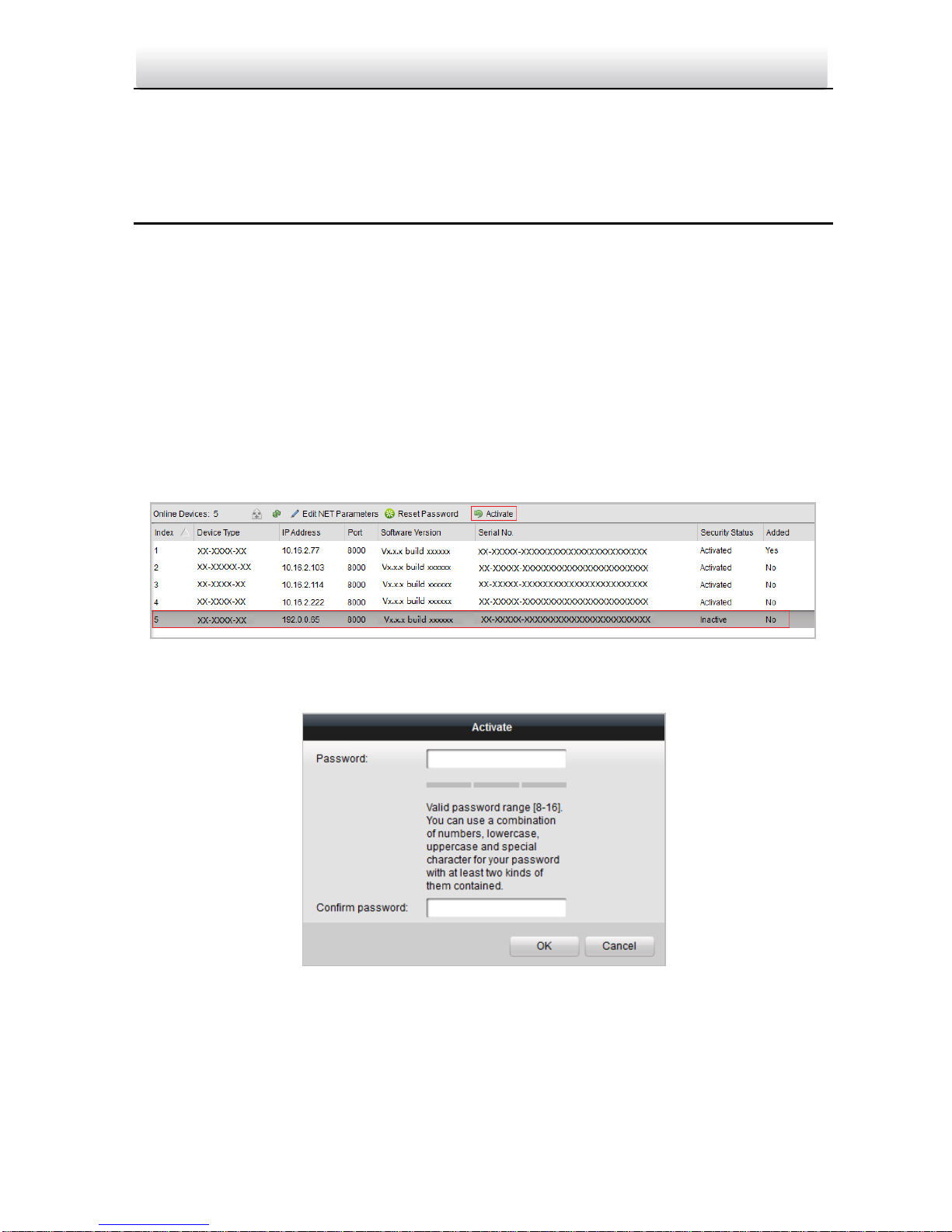
Figure 6-1 Selecting Inactive Device
2. Select an inactivated device and click the Activate button.
Figure 6-2 Activation
3. Create a password, and confirm the password.
Page 30
23
Video Intercom Door Station·Quick Start Guide
4. Click the OK button to activate the device.
When the device is not activated, the basic operation and remote operation of device
cannot be performed.
You can hold the Ctrl or Shift key to select multiple devices in the online devices, and
click the Activate button to activate devices in batch.
6.2 Editing Network Parameters
Purpose:
To operate and configure the device via LAN (Local Area Network), you need connect the
device in the same subnet with you PC. You can edit network parameters via batch
configuration tool, and VEZPRO software. Here take editing network parameters via batch
configuration tool as example.
Steps:
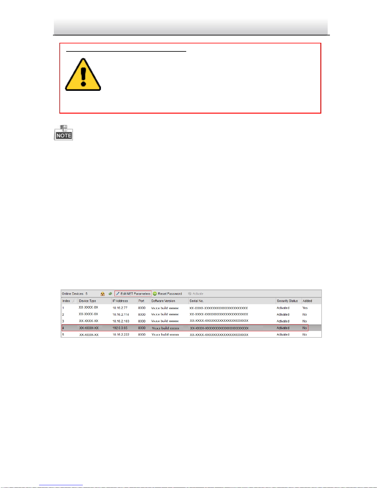
1. Select an online activated device and click the Edit NET Parameters button.
Figure 6-3 Clicking Edit NET Parameters Button
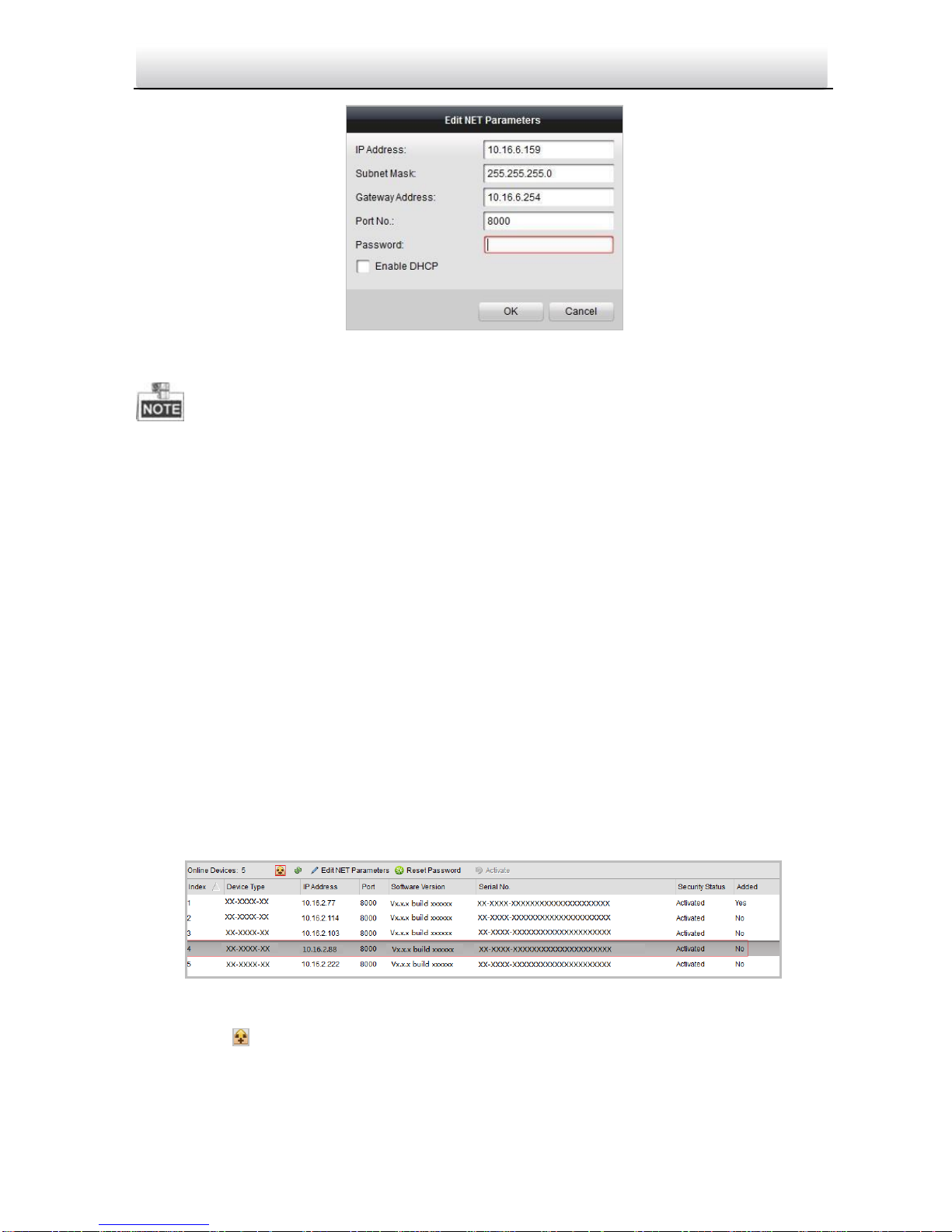
2. Change the device IP address and gateway address to the same subnet with your
computer.
3. Enter the password and click the OK button to activate the network parameters
modification.
STRONG PASSWORD RECOMMENDED– We highly recommend you create a
strong password of your own choosing (Using a minimum of 8
characters, including at least three of the following categories:
upper case letters, lower case letters, numbers, and special
characters.) in order to increase the security of your product. And
we recommend you reset your password regularly, especially in the
high security system, resetting the password monthly or weekly can better
protect your product.
Page 31
24
Video Intercom Door Station·Quick Start Guide
Figure 6-4 Editing Network Parameters
The default port No. is 8000.
After editing the network parameters of device, you should add the devices to the
device list again.
6.3 Adding Device
For batch configuration tool and VEZPRO software, you should add device to the
software so as to configure the device remotely.
3 ways for adding the device are supported: adding active online devices within your
subnet, adding device by IP address, and adding device by IP segment. Here take adding
online device and adding device by IP address via batch configuration tool as example.
6.3.1 Adding Online Device
Steps:
1. Select an active online device or hold the Ctrl or Shift key to select multiple devices in
the online devices list.
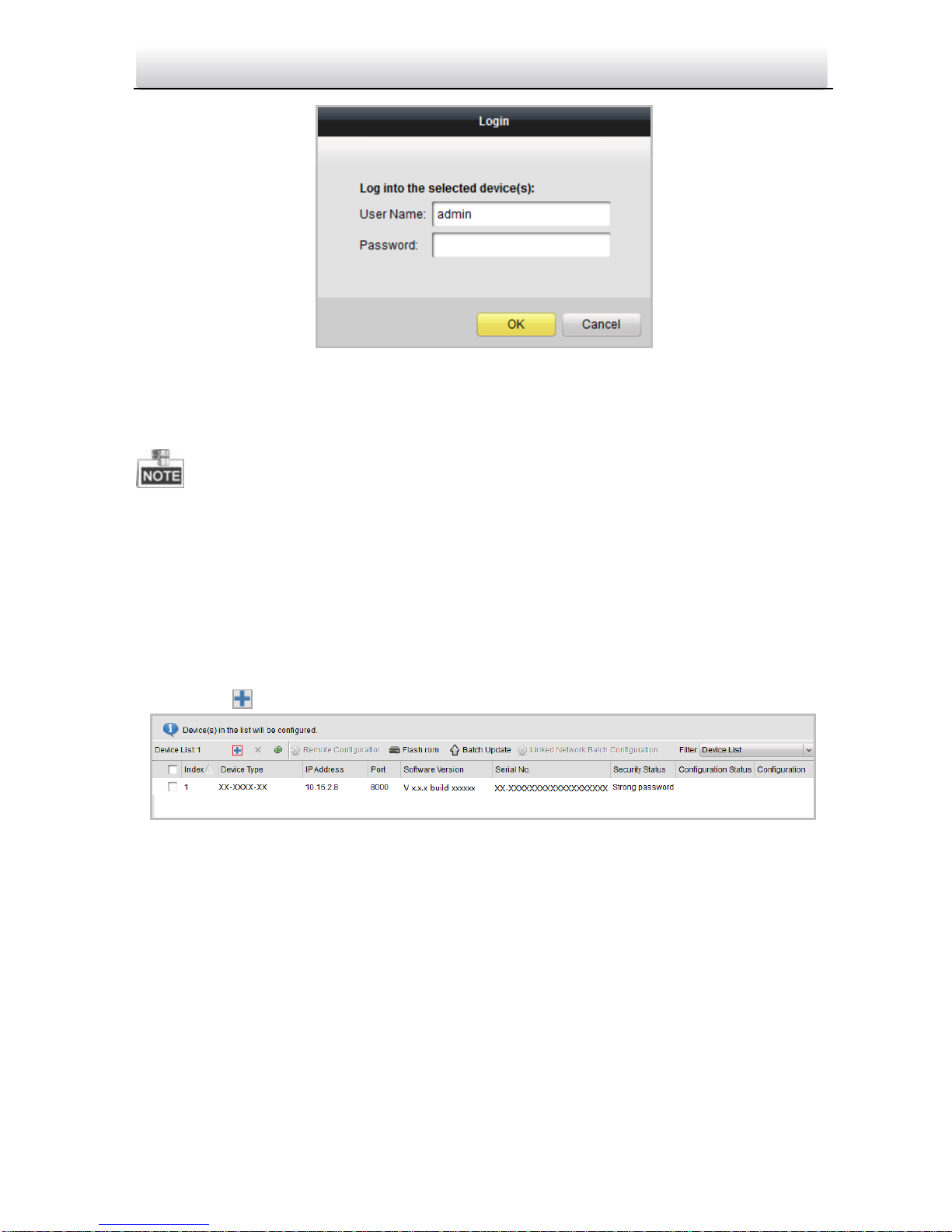
Figure 6-5 Online Devices Interface
2. Click the button to pop up the login dialog box.
Page 32
25
Video Intercom Door Station·Quick Start Guide
Figure 6-6 Login Dialog Box
3. Enter the user name and password.
4. Click the OK button to save the settings.
Only devices successfully logged in will be added to the device list for configuration.
If you add devices in batch, please make sure selected devices have the same user
name and password.
6.3.2 Adding by IP Address
Purpose:
You can add the device by entering IP address.
Steps:
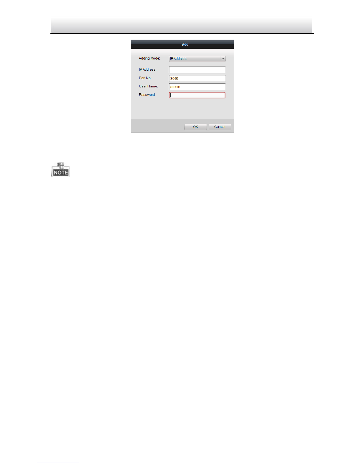
Figure 6-7 Adding Button
2. Select IP Address in the adding mode drop-down list.
3. Enter the IP address, and set the port No., user name and password of the device.
1. Click the button to pop up the adding devices dialog box.
Page 33
26
Video Intercom Door Station·Quick Start Guide
Figure 6-8 Adding by IP Address
4. Click the OK button to add the device to the device list.
You cannot add the device(s) to the device list if the user name and password are not
identical.
When you add devices by IP Address, IP Segment or Port No., the devices should be
online devices.
Page 34
27
Video Intercom Door Station·Quick Start Guide
Appendix
Installation Notice
While installing the indoor station, make sure that the distance between any two
devices is far enough to avoid the howling and echo. The distance between two devices
is recommended to be longer than 10 meters.
Here devices refer to indoor station, outdoor station and master station.
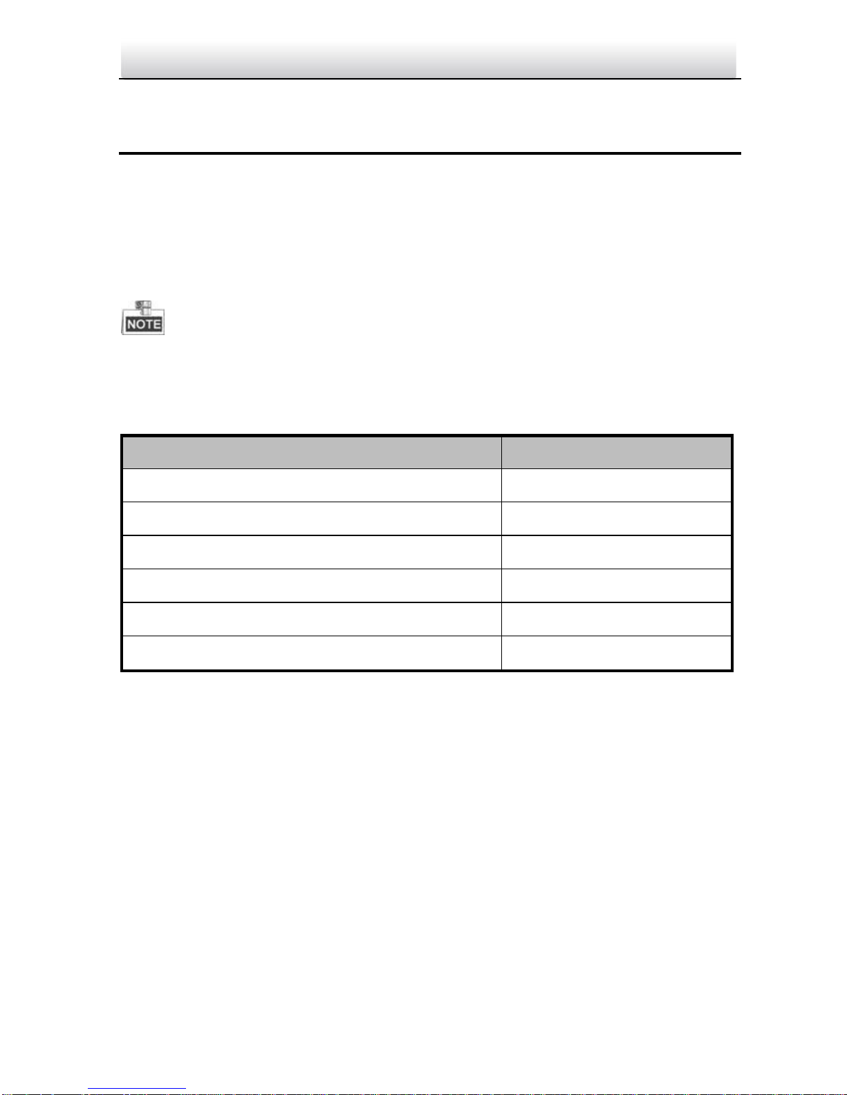
Wiring Cables
Cable
Specification
Power Cord of Door Station
RVV 2*1.0
Network Cable of Door Station
UTP-five Categories
Door Lock Wiring (With Door Magnetic)
RVV 4*1.0
Door Lock Wiring (Without Door Magnetic)
RVV 2*1.0
Exit Button Wiring
RVV 2*0.5
External Card Reader Wiring
RVVP 4*0.75
Page 35

 Loading...