

Vezco VZ-IP-D4030MZVF Quick Start Manual

1
NETWORK DOME CAMERA
Quick Start Guide

Network Dome Camera·Quick Start Guide
2
2
Quick Start Guide
About this Manual
This Manual is applicable to Network Dome Camera.
The Manual includes instructions for using and managing the
product. Pictures, charts, images and all other information
hereinafter are for description and explanation only. The
information contained in the Manual is subject to change, without
notice, due to firmware updates or other reasons. Please find the
latest version in the company website www.vezcocctv.com.
Please use this user manual under the guidance of professionals.
Legal Disclaimer
REGARDING TO THE PRODUCT WITH INTERNET ACCESS, THE USE OF
PRODUCT SHALL BE WHOLLY AT YOUR OWN RISKS. OUR COMPANY
SHALL NOT TAKE ANY RESPONSIBILITES FOR ABNORMAL OPERATION,
PRIVACY LEAKAGE OR OTHER DAMAGES RESULTING FROM CYBER
ATTACK, HACKER ATTACK, VIRUS INSPECTION, OR OTHER INTERNET
SECURITY RISKS; HOWEVER, OUR COMPANY WILL PROVIDE TIMELY
TECHNICAL SUPPORT IF REQUIRED.
SURVEILLANCE LAWS VARY BY JURISDICTION. PLEASE CHECK ALL
RELEVANT LAWS IN YOUR JURISDICTION BEFORE USING THIS
PRODUCT IN ORDER TO ENSURE THAT YOUR USE CONFORMS THE
APPLICABLE LAW. OUR COMPANY SHALL NOT BE LIABLE IN THE
EVENT THAT THIS PRODUCT IS USED WITH ILLEGITIMATE PURPOSES.
IN THE EVENT OF ANY CONFLICTS BETWEEN THIS MANUAL AND THE
APPLICABLE LAW, THE LATER PREVAILS.

Network Dome Camera·Quick Start Guide
3
3
Regulatory Information
FCC Information
Please take attention that changes or modification not expressly
approved by the party responsible for compliance could void the
user’s authority to operate the equipment.
FCC compliance: This equipment has been tested and found to
comply with the limits for a Class B digital device, pursuant to part
15 of the FCC Rules. These limits are designed to provide reasonable
protection against harmful interference in a residential installation.
This equipment generates, uses and can radiate radio frequency
energy and, if not installed and used in accordance with the
instructions, may cause harmful interference to radio
communications. However, there is no guarantee that interference
will not occur in a particular installation. If this equipment does
cause harmful interference to radio or television reception, which
can be determined by turning the equipment off and on, the user is
encouraged to try to correct the interference by one or more of the
following measures:
—Reorient or relocate the receiving antenna.
—Increase the separation between the equipment and receiver.
—Connect the equipment into an outlet on a circuit different from
that to which the receiver is connected.
—Consult the dealer or an experienced radio/TV technician for help
FCC Conditions
This device complies with part 15 of the FCC Rules. Operation is
subject to the following two conditions:
Network Dome Camera·Quick Start Guide
4
4
1. This device may not cause harmful interference.
2. This device must accept any interference received, including
interference that may cause undesired operation.
EU Conformity Statement
This product and - if applicable - the supplied
accessories too are marked with "CE" and comply
therefore with the applicable harmonized European
standards listed under the EMC Directive 2014/30/EU, the RoHS
Directive 2011/65/EU.
2012/19/EU (WEEE directive): Products marked
with this symbol cannot be disposed of as unsorted
municipal waste in the European Union. For proper
recycling, return this product to your local supplier
upon the purchase of equivalent new equipment, or dispose of it at
designated collection points. For more information see:
www.recyclethis.info
2006/66/EC (battery directive): This product
contains a battery that cannot be disposed of as
unsorted municipal waste in the European Union.
See the product documentation for specific battery
information. The battery is marked with this symbol,
which may include lettering to indicate cadmium (Cd), lead (Pb), or
mercury (Hg). For proper recycling, return the battery to your
supplier or to a designated collection point. For more information
see: www.recyclethis.info.
Safety Instruction
Network Dome Camera·Quick Start Guide
5
5
These instructions are intended to ensure that user can use the
product correctly to avoid danger or property loss.
The precaution measure is divided into “Warnings” and “Cautions”
Warnings: Serious injury or death may occur if any of the warnings
are neglected.
Cautions: Injury or equipment damage may occur if any of the
cautions are neglected.
Warnings
● Proper configuration of all passwords and other security
settings is the responsibility of the installer and/or end-user.
● In the use of the product, you must be in strict compliance with
the electrical safety regulations of the nation and region. Please
refer to technical specifications for detailed information.
● Input voltage should meet both the SELV (Safety Extra Low
Voltage) and the Limited Power Source with 24 V AC or 12 V DC
according to the IEC60950-1 standard. Please refer to technical
specifications for detailed information.
Warnings Follow these
safeguards to prevent
serious injury or death.
Cautions Follow these
precautions to prevent potential
injury or material damage.
Network Dome Camera·Quick Start Guide
6
6
● Do not connect several devices to one power adapter as
adapter overload may cause over-heating or a fire hazard.
● Please make sure that the plug is firmly connected to the power
socket. When the product is mounted on wall or ceiling, the
device shall be firmly fixed.
● If smoke, odor or noise rise from the device, turn off the power
at once and unplug the power cable, and then please contact
the service center.
Cautions
● Make sure the power supply voltage is correct before using the
camera.
● Do not drop the camera or subject it to physical shock.
● Do not touch sensor modules with fingers. If cleaning is
necessary, use clean cloth with a bit of ethanol and wipe it
gently. If the camera will not be used for an extended period,
please replace the lens cap to protect the sensor from dirt.
● Do not aim the camera at the sun or extra bright places.
Blooming or smearing may occur otherwise (which is not a
malfunction), and affect the endurance of sensor at the same
time.
● The sensor may be burned out by a laser beam, so when any
laser equipment is in using, make sure that the surface of
sensor will not be exposed to the laser beam.
● Do not place the camera in extremely hot, cold (the operating
temperature shall be-30°C to +60°C, or -40°C to +60°C if the

Network Dome Camera·Quick Start Guide
7
7
camera model has an “H” in its suffix), dusty or damp locations,
and do not expose it to high electromagnetic radiation.
● To avoid heat accumulation, good ventilation is required for
operating environment.
● Keep the camera away from liquid while in use.
● While in delivery, the camera shall be packed in its original
packing, or packing of the same texture.
● Regular part replacement: a few parts (e.g. electrolytic
capacitor) of the equipment shall be replaced regularly
according to their average enduring time. The average time
varies because of differences between operating environment
and using history, so regular checking is recommended for all
the users. Please contact with your dealer for more details.
● Improper use or replacement of the battery may result in
hazard of explosion. Replace with the same or equivalent type
only. Dispose of used batteries according to the instructions
provided by the battery manufacturer.
● If the product does not work properly, please contact your
dealer or the nearest service center. Never attempt to
disassemble the camera yourself. (We shall not assume any
responsibility for problems caused by unauthorized repair or
maintenance.)

Network Dome Camera·Quick Start Guide
8
8
Table of Contents
1 Appearance Description ............................................................. 10
1.1 Type I Camera ............................................................... 10
1.1.1 Overview ................................................................. 10
1.1.2 Cable Description .................................................... 12
1.2 Type II Camera .............................................................. 13
1.2.1 Overview ................................................................. 14
1.2.2 Cable Description .................................................... 15
2 Installation ................................................................................. 17
Preparation ................................................................... 18
2.1.1 Disassembling .......................................................... 18
2.1.2 Memory Card Installation ........................................ 19
Mounting ...................................................................... 21
2.2.1 Ceiling Mounting ..................................................... 21
2.2.2 In-ceiling Mounting.................................................. 25
2.2.3 Mounting with Wall Mounting Bracket .................... 29
2.2.4 Mounting with Pendant Mounting Bracket .............. 32
2.2.5 Mounting with Junction box .................................... 35
2.3 Image and Focus Adjusting ............................................ 37
2.3.1 3-Axis Adjustment ................................................... 38
2.3.2 Zoom and Focus Adjustment. .................................. 39
3 Setting the Network Camera over the LAN ................................. 42
Wiring ........................................................................... 42
Activating the Camera ................................................... 43
3.2.1 Activation via Web Browser ..................................... 43
3.2.2 Activation via SADP Software ................................... 44
Modifying the IP Address .............................................. 46

Network Dome Camera·Quick Start Guide
9
9
4 Accessing via Web Browser ........................................................ 50
5 Operating via GUARDING VISION App ........................................ 52
Enable GUARDING VISION Service on Camera .............. 52
5.1.1 Enable GUARDING V. Service via SADP Software ..... 52
5.1.2 Enable GUARDING VISION Service via Web Browser 53
GUARDING VISION Setup .............................................. 55
Adding Camera to GUARDING VISION ........................... 55
Initializing the Memory Card ......................................... 57
Network Dome Camera·Quick Start Guide
10
10
1 Appearance Description
This series of cameras has two appearance types.
1.1 Type I Camera
Type I camera has different models. Some models have the lens that
zoom and focus levels must be manually adjusted via zoom/focus
lever and some models have a motor-driven lens that zoom and
focus adjustment can be completed via web browser or client
software. Please refer to the actual device.
1.1.1 Overview
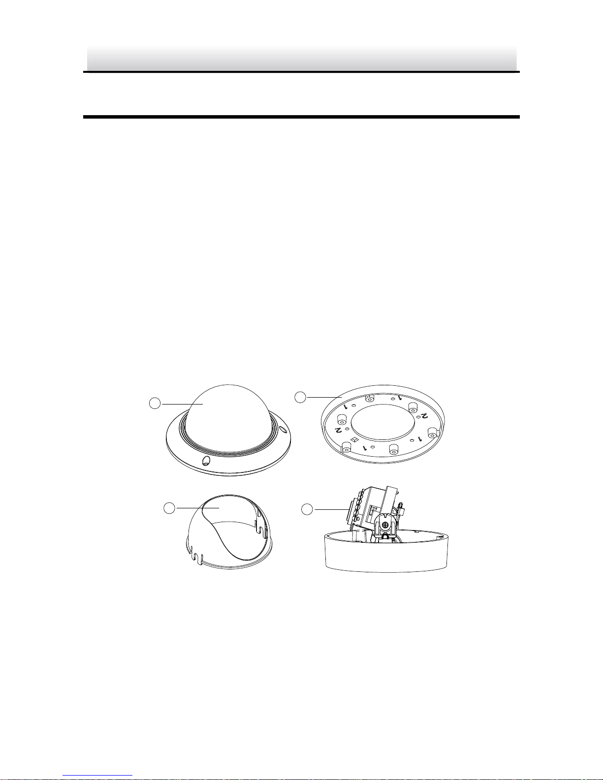
The overview of the Type I network dome camera is shown below.
1
2
3
4
Figure 1-1 Overview of Type I Camera (1)

Network Dome Camera·Quick Start Guide
11
11
5
6
7
8
Figure 1-2 Overview of Type I Camera (2)
Table 1-1 Overview of Type I Camera
No.
Description
1
Bubble
2
Black Liner
3
Lens
4
Mounting Base
5
Reset
6
Auxiliary Video Output
7
Serial Port
8
Memory Card Slot
Network Dome Camera·Quick Start Guide
12
12
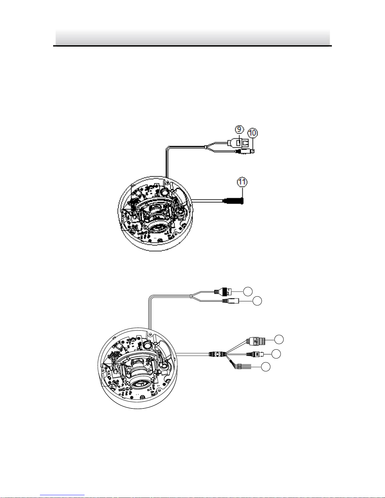
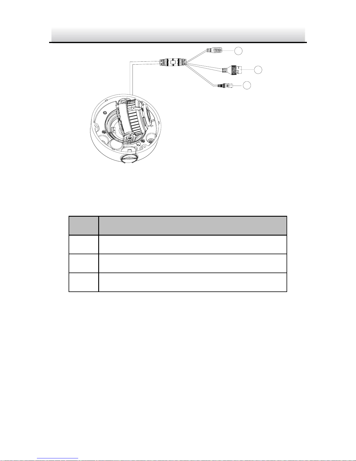
1.1.2 Cable Description
Cable description of the Type I network dome camera is shown
below.
Note: Cables vary according to different models as the figures below.
Figure 1-3 Cable Description of Type I Camera (1)
10
12
9
14
13
Figure 1-4 Cable Description of Type I Camera (2)
Network Dome Camera·Quick Start Guide
13
13
Table 1-2 Cable Description
No.
Description
9
Network Interface
10
Power Supply Interface
11
Audio/Alarm Interface
12
Audio Input and Output Interface
13
Video Output Interface
14
Alarm Input and Output Interface
Notes:
Power on the camera when pressing the RESET button, and press
button for another 10 seconds to restore the default settings,
including the user name, password, IP address, port No., etc.
Some of the models support audio and alarm functions.
1.2 Type II Camera
Type II camera has different models. Some models have the lens that
zoom and focus levels must be manually adjusted via zoom/focus
lever and some models have a motor-driven lens that zoom and
focus adjustment can be completed via web browser or client
software. Please refer to the actual device.
Network Dome Camera·Quick Start Guide
14
14
1.2.1 Overview
The overview of the Type II network dome camera is shown below.
2
3
1
Overview of Type II Camera (1)
4
5
Overview of Type II Camera (2)
Network Dome Camera·Quick Start Guide
15
15
Overview of Type II Camera
No.
Description
1
Bubble
2
Black Liner
3
Lens
4
Reset
5
Memory Card Slot
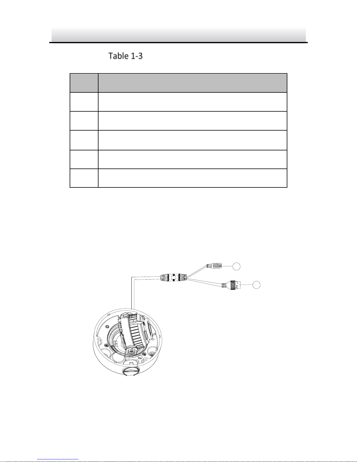
1.2.2 Cable Description
Cable description of the Type II network dome camera is shown
below.
Note: Cables vary according to different models as the figures below.
D
C
1
2
V
I
N
6
7
Figure 1-7 Cable Description of Type II Camera (1)
Network Dome Camera·Quick Start Guide
16
16
8
D
C
1
2
V
I
N
6
7
Figure 1-8 Cable Description of Type II Camera (2)
Table 1-4 Cable Description
No.
Description
6
Power Supply Interface
7
Network Interface
8
Video Output Interface
Note: Power on the camera when pressing the REST button, and
press button for another 10 seconds to restore the default settings,
including the user name, password, IP address, port No., etc

Network Dome Camera·Quick Start Guide
17
17
2 Installation
Before you start:
● Make sure the device in the package is in good condition and all
the assembly parts are included.
● The standard power supply is 12V DC or PoE (802.3af). Make
sure your power supply matches with your camera.
● Make sure all the related equipment is power-off during the
installation.
● Check the specification of the products for the installation
environment.
● Make sure that the wall is strong enough to withstand four
times the weight of the camera and the bracket.
For the camera that supports IR, you are required to pay attention to
the following precautions to prevent IR reflection:
● Dust or grease on the dome cover will cause IR reflection.
Please do not remove the dome cover film until the installation
is finished. If there is dust or grease on the dome cover, clean
the dome cover with clean soft cloth and isopropyl alcohol.
● Make sure that there is no reflective surface too close to the
camera lens. The IR light from the camera may reflect back into
the lens causing reflection.
● The foam ring around the lens must be seated flush against the
inner surface of the bubble to isolate the lens from the IR LEDS.
Fasten the dome cover to camera body so that the foam ring
and the dome cover are attached seamlessly.
Network Dome Camera·Quick Start Guide
18
18
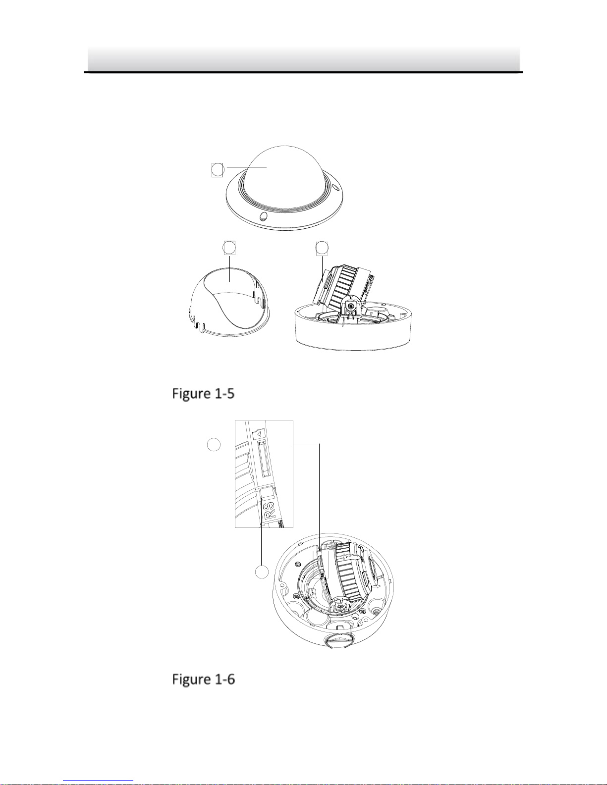
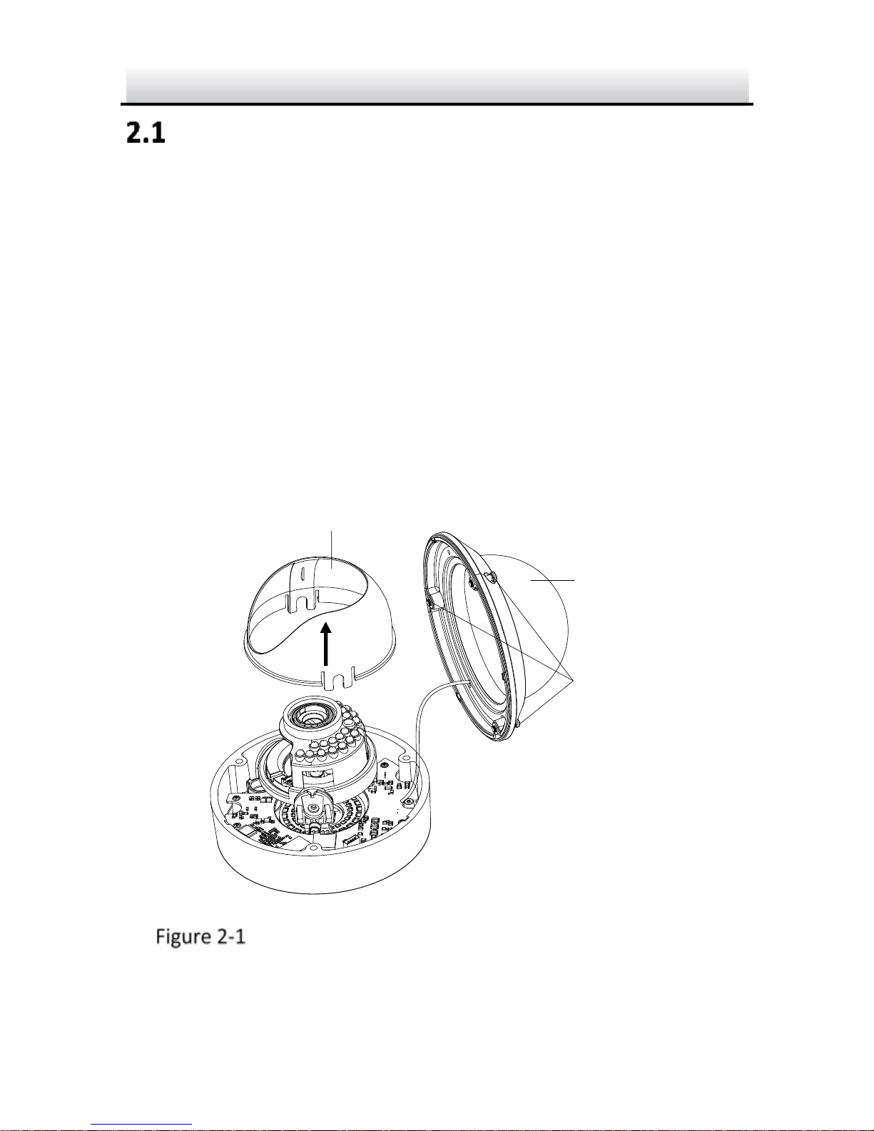
Preparation
Purpose:
Before mounting, you have to disassemble the camera and install the
memory card first.
2.1.1 Disassembling
Steps:
1. Loosen the three screws on the edge of the bubble with the screw
driver.
2. Lift and put aside the bubble.
3. Remove the inner black liner.
Black Liner
Bubble
Screws
Remove the Bubble and Black Liner (Type I Camera)
 Loading...