

Vezco VZ-IP-BUTIDS-WI User Manual

Video Intercom Indoor
Station
User Manual

Video Intercom Indoor Station·User Manual
i
User Manual
It includes instructions on how to use the Product. The software embodied in the
Product is governed by the user license agreement covering that Product.
Disclaimer
REGARDING TO THE PRODUCT WITH INTERNET ACCESS, THE USE OF PRODUCT SHALL BE WHOLLY
AT YOUR OWN RISKS. OUR COMPANY SHALL NOT TAKE ANY RESPONSIBILITES FOR ABNORMAL
OPERATION, PRIVACY LEAKAGE OR OTHER DAMAGES RESULTING FROM CYBER ATTACK, HACKER
ATTACK, VIRUS INSPECTION, OR OTHER INTERNET SECURITY RISKS; HOWEVER, OUR COMPANY
WILL PROVIDE TIMELY TECHNICAL SUPPORT IF REQUIRED.
SURVEILLANCE LAWS VARY BY JURISDICTION. PLEASE CHECK ALL RELEVANT LAWS IN YOUR
JURISDICTION BEFORE USING THIS PRODUCT IN ORDER TO ENSURE THAT YOUR USE CONFORMS
THE APPLICABLE LAW. OUR COMPANY SHALL NOT BE LIABLE IN THE EVENT THAT THIS PRODUCT IS
USED WITH ILLEGITIMATE PURPOSES.
IN THE EVENT OF ANY CONFLICTS BETWEEN THIS MANUAL AND THE APPLICABLE LAW, THE LATER
PREVAILS.
Support
Should you have any questions, please do not hesitate to contact us.
ii
Video Intercom Indoor Station·User Manual
Regulatory Information
FCC Information
Please take attention that changes or modification not expressly approved by the party
responsible for compliance could void the user’s authority to operate the equipment.
FCC compliance: This equipment has been tested and found to comply with the limits
for a Class A digital device, pursuant to part 15 of the FCC Rules. These limits are
designed to provide reasonable protection against harmful interference when the
equipment is operated in a commercial environment. This equipment generates, uses,
and can radiate radio frequency energy and, if not installed and used in accordance with
the instruction manual, may cause harmful interference to radio communications.
Operation of this equipment in a residential area is likely to cause harmful interference
in which case the user will be required to correct the interference at his own expense.
FCC Conditions
This device complies with part 15 of the FCC Rules. Operation is subject to the following
two conditions:
1. This device may not cause harmful interference.
2. This device must accept any interference received, including interference that may
cause undesired operation.
EU Conformity Statement
This product and - if applicable - the supplied accessories too are
marked with "CE" and comply therefore with the applicable harmonized
European standards listed under the EMC Directive 2004/108/EC, the
RoHS Directive 2011/65/EU.
2012/19/EU (WEEE directive): Products marked with this symbol cannot
be disposed of as unsorted municipal waste in the European Union. For
proper recycling, return this product to your local supplier upon the
purchase of equivalent new equipment, or dispose of it at designated
collection points. For more information see: www.recyclethis.info
2006/66/EC (battery directive): This product contains a battery that
cannot be disposed of as unsorted municipal waste in the European
Union. See the product documentation for specific battery information.
The battery is marked with this symbol, which may include lettering to
indicate cadmium (Cd), lead (Pb), or mercury (Hg). For proper recycling,
return the battery to your supplier or to a designated collection point.
For more information see: www.recyclethis.info
Industry Canada ICES-003 Compliance
This device meets the CAN ICES-3 (A)/NMB-3(A) standards requirements.
Video Intercom Indoor Station·User Manual
iii
Safety Instruction
These instructions are intended to ensure that user can use the product correctly to
avoid danger or property loss.
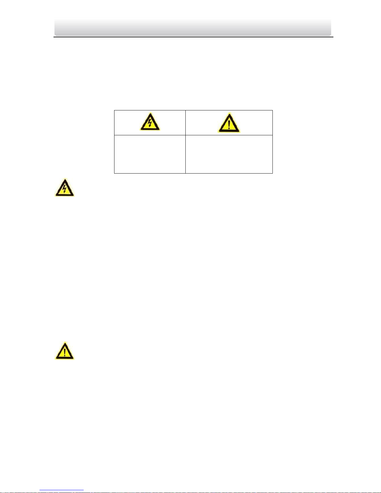
The precaution measure is divided into Warnings and Cautions:
Warnings: Neglecting any of the warnings may cause serious injury or death.
Cautions: Neglecting any of the cautions may cause injury or equipment damage.
Warnings Follow
Cautions Follow these
these safeguards to
precautions to prevent
prevent serious
potential injury or
injury or death.
material damage.
Warnings
All the electronic operation should be strictly compliance with the electrical safety
regulations, fire prevention regulations and other related regulations in your local
region.
Please use the power adapter, which is provided by normal company. The power
consumption cannot be less than the required value.
Do not connect several devices to one power adapter as adapter overload may cause
over-heat or fire hazard.
Please make sure that the power has been disconnected before you wire, install or
dismantle the device.
When the product is installed on wall or ceiling, the device shall be firmly fixed.
If smoke, odors or noise rise from the device, turn off the power at once and unplug the
power cable, and then please contact the service center.
If the product does not work properly, please contact your dealer or the nearest service
center. Never attempt to disassemble the device yourself. (We shall not assume any
responsibility for problems caused by unauthorized repair or maintenance.)
Cautions
Do not drop the device or subject it to physical shock, and do not expose it to high
electromagnetism radiation. Avoid the equipment installation on vibrations surface or
places subject to shock (ignorance can cause equipment damage).
Do not place the device in extremely hot (refer to the specification of the device for the
detailed operating temperature), cold, dusty or damp locations, and do not expose it to
high electromagnetic radiation.
The device cover for indoor use shall be kept from rain and moisture.
Exposing the equipment to direct sun light, low ventilation or heat source such as heater
or radiator is forbidden (ignorance can cause fire danger).

Video Intercom Indoor Station·User Manual
iv
Do not aim the device at the sun or extra bright places. A blooming or smear may occur
otherwise (which is not a malfunction however), and affecting the endurance of sensor
at the same time.
Please use the provided glove when open up the device cover, avoid direct contact with
the device cover, because the acidic sweat of the fingers may erode the surface coating
of the device cover.
Please use a soft and dry cloth when clean inside and outside surfaces of the device
cover, do not use alkaline detergents.
Please keep all wrappers after unpack them for future use. In case of any failure
occurred, you need to return the device to the factory with the original wrapper.
Transportation without the original wrapper may result in damage on the device and
lead to additional costs.
Improper use or replacement of the battery may result in hazard of explosion. Replace
with the same or equivalent type only. Dispose of used batteries according to the
instructions provided by the battery manufacturer.

Video Intercom Indoor Station·User Manual
v
Table of Contents
1 Overview ................................................................................................ 1
1.1 Introduction .......................................................................................................... 1
1.2 Main Features ....................................................................................................... 1
2 Appearance ............................................................................................. 2
2.1 Appearance of Indoor Station…………………………………………………….………………………2
3 Typical Application .................................................................................. 4
4 Terminals and Interfaces .......................................................................... 5
4.1 Terminals and Interfaces of Indoor Station………………………………………………..………5
5 Installation and Wiring ............................................................................ 6
5.1 Indoor Station Installation .................................................................................... 6
5.1.1 Wall Mounting Plate ...................................................................................... 6
5.1.2 Wall Mounting with Junction Box .................................................................. 6
5.2 Indoor Station Wiring ........................................................................................... 8
5.2.1 Wiring of Indoor Station…………………………………………………….………………………..8
6 Before You Start .................................................................................... 10
7 Local Operation ..................................................................................... 11
7.1 Activating Device Locally .................................................................................... 11
7.2 User Interface Description .................................................................................. 13
7.2.1 User Interface of Indoor Station ................................................................... 13
7.2.2 User Interface of Indoor Extension ............................................................... 14
7.2.3 Status of Indoor Station ............................................................................... 15
7.2.4 Status of Indoor Extension ........................................................................... 16
7.2.5 Arming Status ............................................................................................... 17
7.3 Indoor Station Settings ....................................................................................... 18
7.3.1 Password Settings ........................................................................................ 18
7.3.2 Sound Settings ............................................................................................. 20
7.3.3 No Disturbing Settings.................................................................................. 22
7.3.4 Zone Settings ................................................................................................ 23
7.3.5 Arming Mode Settings .................................................................................. 24
7.3.6 System Maintenance .................................................................................... 25
7.3.7 Configuration Settings .................................................................................. 26
7.4 Call Settings ........................................................................................................ 34
7.4.1 Adding Contact ............................................................................................. 34
7.4.2 Calling Resident ............................................................................................ 35
7.4.3 Calling Management Center ........................................................................ 36
7.4.4 Receiving Call ............................................................................................... 37
7.4.5 Viewing Call Logs .......................................................................................... 38

Video Intercom Indoor Station·User Manual
vi
7.5 Live View ....................................................................................................... 40
7.6 Information Management .................................................................................. 42
8 Remote Operation via Batch Configuration Tool ......................................... 44
8.1 Activating Device Remotely ................................................................................ 44
8.2 Editing Network Parameters .............................................................................. 45
8.3 Adding Device ..................................................................................................... 46
8.3.1 Adding Online Device ................................................................................... 46
8.3.2 Adding by IP Address .................................................................................... 47
8.3.3 Adding by IP Segment .................................................................................. 48
8.4 Configuring Devices Remotely ............................................................................ 49
8.4.1 System ................................................................................................................ 49
8.4.2 Video Intercom ............................................................................................ 56
8.4.3 Network ....................................................................................................... 61
8.5 Video Intercom Device Set-up Tool .......................................................................... 64
8.5.1 Setting a Community Structure .................................................................... 64
8.5.2 Setting Indoor Station .................................................................................. 65
8.6 Batch Upgrading ................................................................................................. 66
8.6.1 Adding Devices for Upgrading ...................................................................... 66
8.6.2 Upgrading Devices ....................................................................................... 69
9 Remote Operation via VEZPRO .............................................................. 70
9.1 System Configuration ......................................................................................... 70
9.2 Device Management ........................................................................................... 71
9.2.1 Adding Video Intercom Devices ................................................................... 71
9.2.2 Modifying Network Information .................................................................. 74
9.2.3 Resetting Password ...................................................................................... 75
9.3 Configuring Devices Remotely via VEZPRO ......................................................... 77
9.4 Picture Storage ................................................................................................... 77
9.4.1 Adding Storage Server .................................................................................. 77
9.4.2 Formatting the HDDs.................................................................................... 78
9.4.3 Configuring Storage Server Picture Storage ................................................. 79
9.5 Video Intercom Configuration ............................................................................ 81
9.5.1 Group Management ..................................................................................... 82
9.5.2 Video Intercom ............................................................................................ 88
9.5.3 Card Management ....................................................................................... 91
9.5.4 Notice Management .................................................................................. 101
9.6 Device Arming Control ...................................................................................... 105
10 Accessing via Guarding Vision Mobile Client Software ....................... 107
10.1 Installing Software .......................................................................................... 107
10.1.1 Installing Software (iOS) ........................................................................... 107
10.1.2 Installing Software (Android) ................................................................... 107
10.2 Registering Software ...................................................................................... 108
10.3 Logging in Software ........................................................................................ 111
10.4 Adding Device ................................................................................................. 111
10.4.1 Adding Device via QR Code ...................................................................... 111

Video Intercom Indoor Station·User Manual
vii
10.4.2 Adding Device via Serial No ...................................................................... 112
10.5 Live View and Remote Unlocking ................................................................... 113
Appendix .................................................................................................. 115
Installation Notice ......................................................................................................115
Wiring Cables ..............................................................................................................115

Video Intercom Indoor Station·User Manual
1
1 Overview
1.1 Introduction
The video intercom system can realize functions such as video intercom,
resident-to-resident video call, live view of HD video, access control, one-card system,
elevator linkage, 8-ch zone alarm, notice information and visitor messages to provide a
complete smart community video intercom system.
The video intercom indoor station is mainly applied to situations such as community,
villa, and official buildings.
1.2 Main Features
Video intercom function
Remote unlocking function
Resident-to-resident audio call
Live view of HD video
Voice message function
Auto-respond and no disturbing mode
Noise suppression and echo cancellation
8-ch zone alarm and SOS calling function
Community notice
Convenient installation with the bracket, batch settings, and power over video/audio
distributor
Video Intercom Indoor Station·User Manual
2
2 Appearance
2.1 Appearance of Indoor Station
Table 2-5 Components Description
Figure 2-1 Front Panel
Table 2-6 Components Description
Figure 2-2 Rear Panel
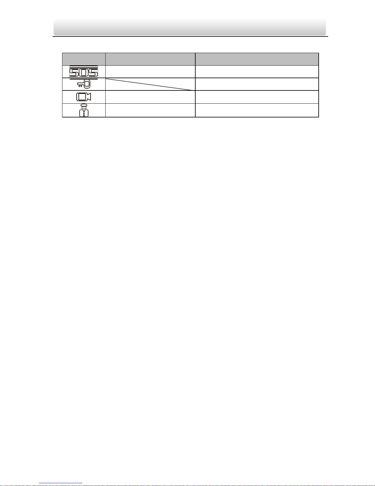
Hold down the SOS key to trigger a SOS alarm and upload the alarm message to the
management center (VEZPRO client software or the master station).
The Unlock key ) is valid only when does the indoor station speak with the door
station or open the live view of the door station.
There are different meanings when you press or hold down the four mechanical
keys.
No.
Description
1
Power Supply Indicator
2
Information Indicator
3
Alarm Indicator
4
SOS Key
5
Unlock Key
6
Live View Key
7
Management Center Key
8
LCD Display Screen
9
Microphone
No.
Description
10
Power Supply
11
Network Interface
12
Terminals
13
Loudspeaker
Video Intercom Indoor Station·User Manual
3
Keys
Hold Down
Press
SOS Key
Return Key
Direction Keys▲and◄/Unlock Key
Live View Key Alarm
Direction Keys▼and►
Management Center Key
Confirm Key

Video Intercom Indoor Station·User Manual
4
LAN
3 Typical Application
Building
PC Client
tation
n
om
One Resident
Door Station
Outer Door Station
Figure 3-1 Typical Application of Indoor Station
Indoor extensions in a resident are in the same LAN with other devices in a video
intercom system.
Video Intercom Indoor Station·User Manual
5
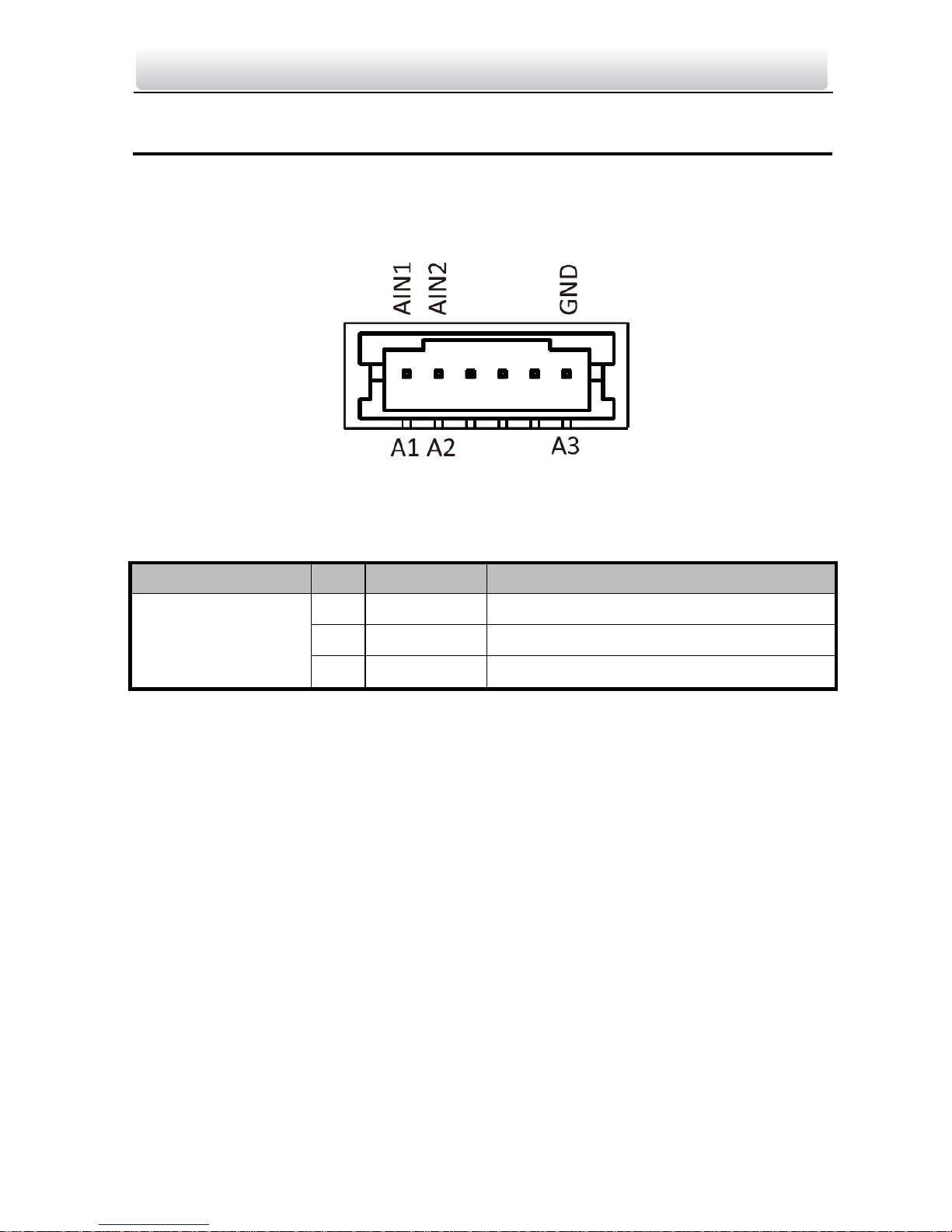
4 Terminals and Interfaces
4.1 Terminals and Interfaces of Indoor Station
Figure 4-1 Terminals of Indoor Station
Table 4-1 Terminals Description
Name
No.
Interface
Description
Terminals
A1
AIN1
Zone Detector Input Terminal 1
A2
AIN2
Zone Detector Input Terminal 2
A3
GND
Grounding
Video Intercom Indoor Station·User Manual
6
5 Installation and Wiring
Before you start:
Make sure the device in the package is in good condition and all the assembly parts
are included.
The power supply the indoor station supports is 12 VDC. Please make sure your
power supply matches your indoor station.
Make sure all the related equipment is power-off during the installation.
Check the product specification for the installation environment.
5.1 Indoor Station Installation
The wall mounting plate and the junction box are required to install the indoor station
onto the wall.
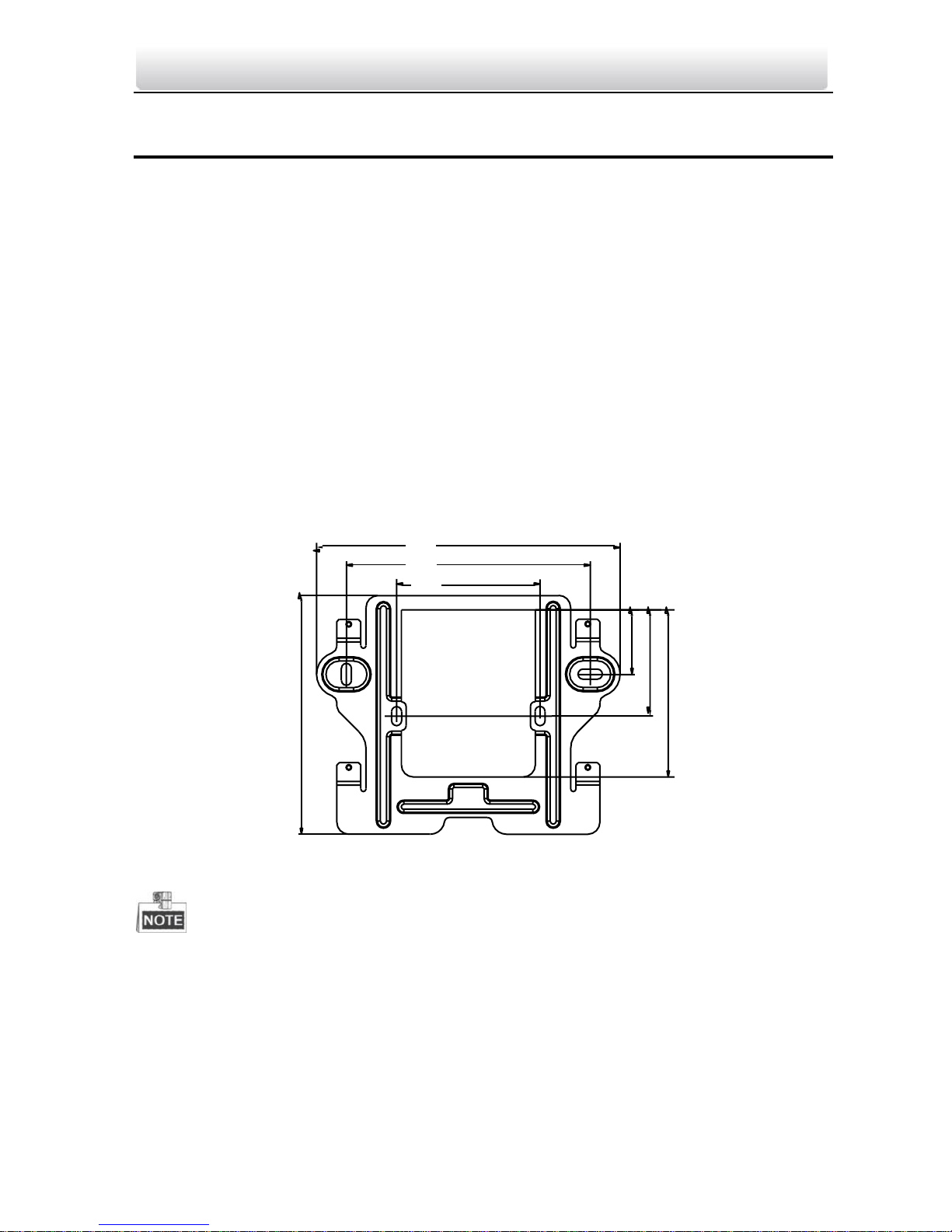
5.1.1 Wall Mounting Plate
127 mm
102 mm
60 mm
Figure 5-1 Wall Mounting Plate
The dimension of junction box should be 75 mm (width) × 75 mm (length) × 50 mm
(depth).
5.1.2 Wall Mounting with Junction Box
100
mm
27
mm
44.5
mm
70
mm
Video Intercom Indoor Station·User Manual
7
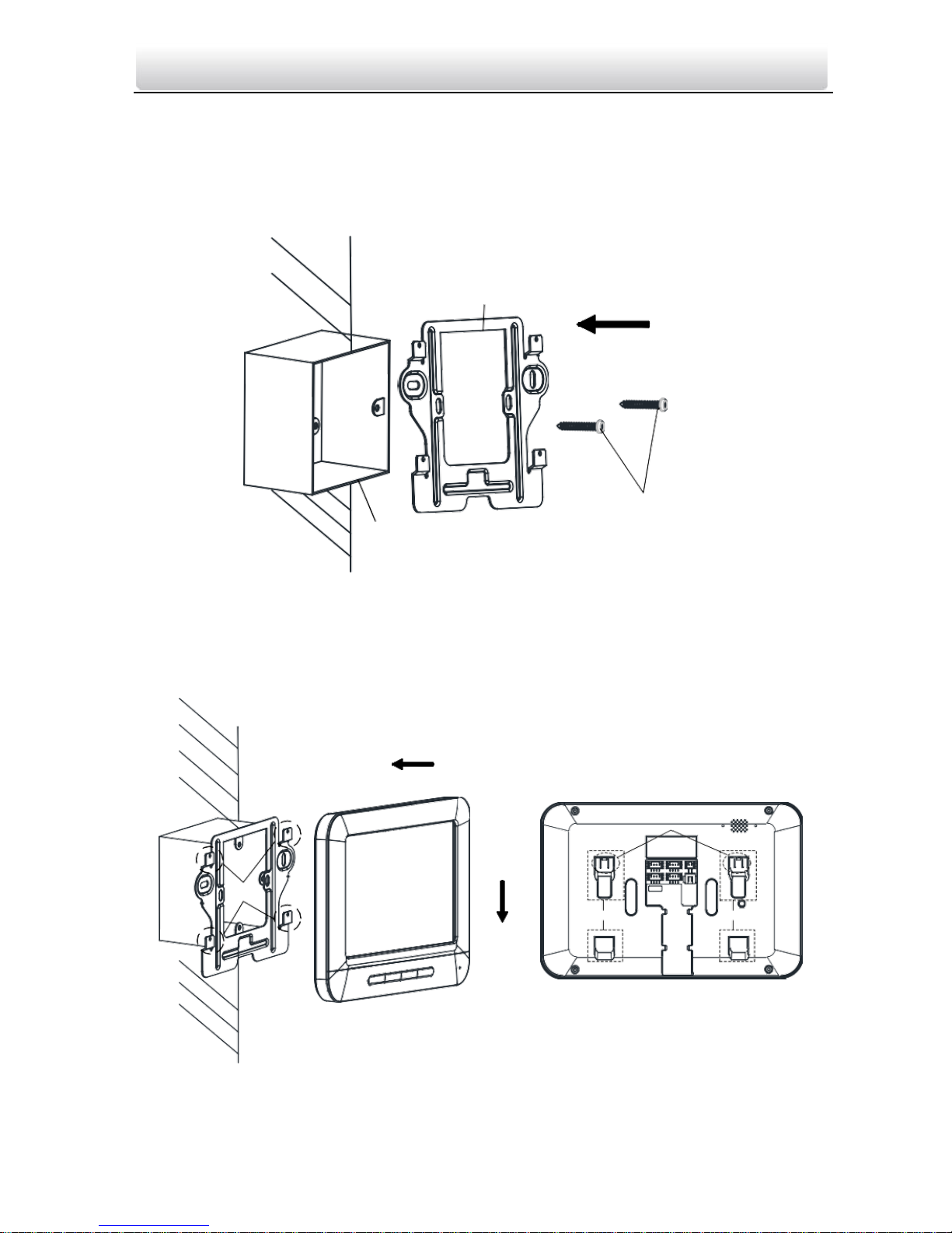
Steps:
1. Chisel a hole in the wall. The size of the hole should be 76 mm (width) × 76 mm
(length) × 50 mm (depth).
2. Insert the junction box to the hole chiseled on the wall.
3. Fix the wall mounting plate to the junction box with 2 screws.
Wall Mounting
Plate
Screws
Junction Box
Figure 5-2 Install the Plate
4. Hook the indoor station to the wall mounting plate tightly by inserting the plate hooks
into the slots on the rear panel of the indoor station, during which the lock catch will
be locked automatically.
Hooks
Lock Catch
Slot Slot
Figure 5-3 Hook the Indoor Station to the Plate
Video Intercom Indoor Station·User Manual
8
5.2 Indoor Station Wiring
5.2.1 Wiring of Indoor Station
Figure 5-4 Wiring of Indoor Station
Video Intercom Indoor Station·User Manual
9
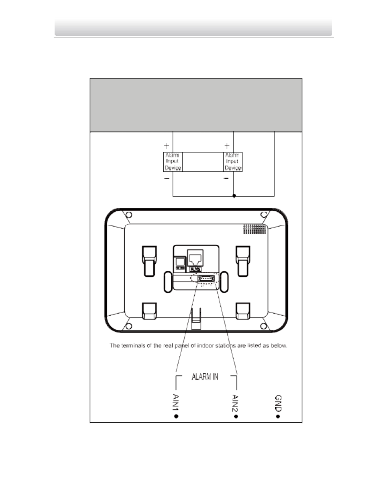
Descriptions of Indoor Station interfaces are shown in the following table.
Interface
Description
ALARM IN
Connect alarm device, with one end of the device connecting
to JINx and the other end connecting to GND (x indicates
number between 1~8).
ALARM OUT
Connect alarm output devices.
GND 12V
Connect to DC power supply 12V.
LAN
Network port of indoor station. Connect the indoor station to
the same LAN with the door station. (Support POE)

Video Intercom Indoor Station·User Manual
10
6 Before You Start
For the first time use of the device, you are required to activate the device and set the
device password. You can activate the device on the UI, via internet with Batch
Configuration Tool, or with VEZPRO client software.
To activate the device on the UI, refer to 7 Local Operation.
To activate the device with Batch Configuration Tool or VEZPRO, refer to
8 Remote Operation via Batch Configuration Tool and 9 Remote
Operation via VEZPRO.
To configure the key parameters of device on the user interface of indoor station, you
are required to input the admin password.
The default admin configuration password is 888999.
The default unlocking password and arming/disarming password are 123456;
The default duress code is 654321.
You must change these default credentials to protect against unauthorized access to the
product.
Video Intercom Indoor Station·User Manual
11
7 Local Operation
Here the local operation of indoor stations with touch screen is taken as example.
The indoor station should be operated with physical keys. The SOS key works as a
return key; the Unlock key works as direction keys ▲and◄ to turn up and left; the
Live View key works as direction keys ▼and► to turn down and right; and the
Management Center key works as a confirm key.
7.1 Activating Device Locally
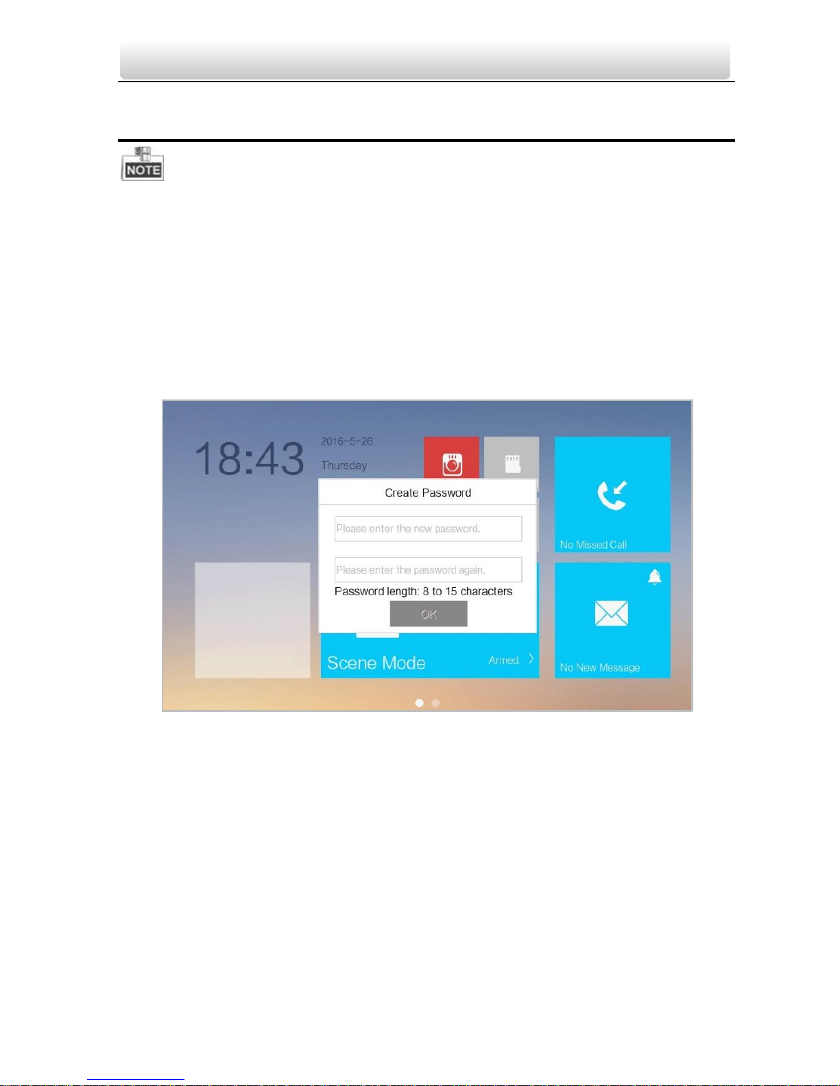
Steps:
1. Power on the device to enter the activation interface automatically.
Figure 7-1 Activation Interface
2. Create a password and confirm it.
3. Press the OK button to activate the device.

Video Intercom Indoor Station·User Manual
12
STRONG PASSWORD RECOMMENDED– We highly recommend you to create a strong
password of your own choosing (using a minimum of 8 characters, including
at least three kinds of following categories: upper case letters, lower case
letters, numbers, and special characters) in order to increase the security of
your product. And we recommend you reset your password regularly, especially in the
high security system, resetting the password monthly or weekly can better protect your
product.
Video Intercom Indoor Station·User Manual
13
You must create a password to activate the device for your first time usage and when
it is not activated.
Only when the device is activated, can you operate it locally and remotely.
7.2 User Interface Description
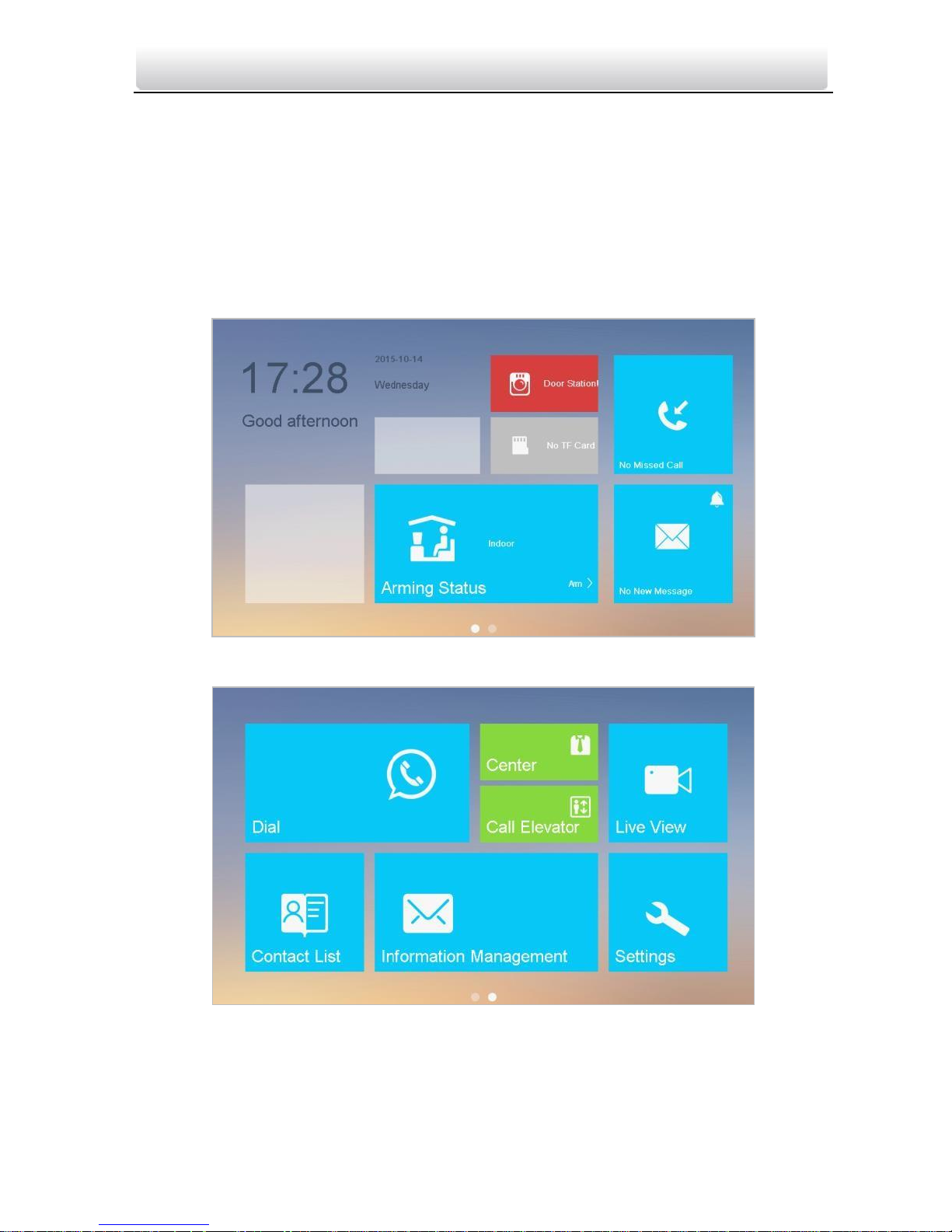
7.2.1 User Interface of Indoor Station
Figure 7-2 User Interface of Indoor Station (Page 1)
Figure 7-3 User Interface of Indoor Station (Page 2)
Video Intercom Indoor Station·User Manual
14
Indoor station only has one interface page.
Figure 7-4 User Interface of Indoor Station
7.2.2 User Interface of Indoor Extension
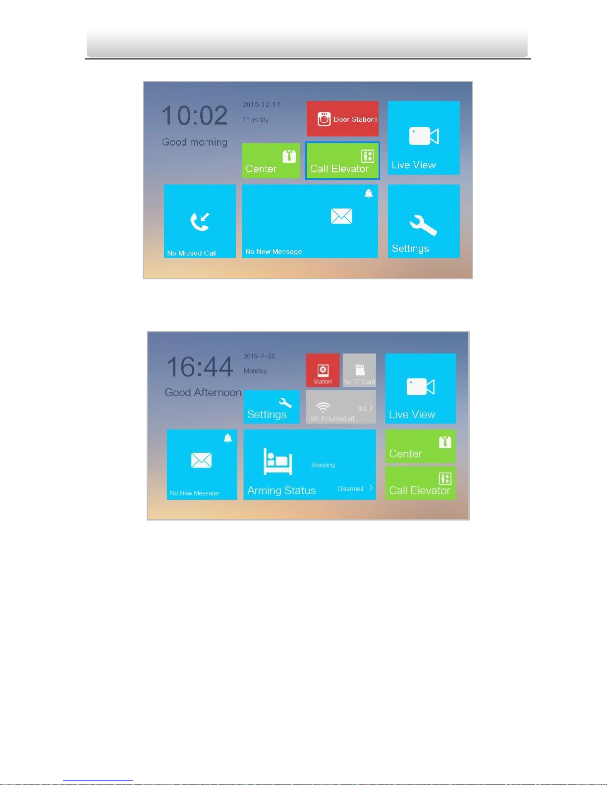
Figure 7-5 User Interface of Indoor Extension
Video Intercom Indoor Station·User Manual
15
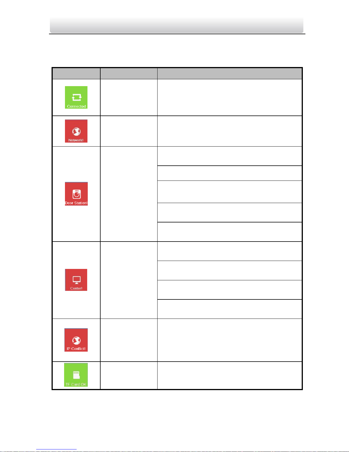
7.2.3 Status of Indoor Station
Table 7-1 Description of Status Icons
Icon
Definition
Description
Normal Status.
The communication between indoor station,
door station and master station is normal.
And the communication between indoor
station and indoor extension is normal.
The indoor
station is offline.
Please check the network cable or Wi-Fi
connection.
Exception occurs
in the
communication
with door
station.
Room No. conflict. Configure the Room No.
again.
Invalid Room No.. Configure the Room No..
Invalid main door station IP address. Configure
the main door station IP address.
Network of door station is abnormal. Check the
network connection of main door station.
Communication of door station is abnormal.
Check if the door station IP address is correct.
The indoor
station has not
registered in the
SIP server.
Invalid SIP server IP address. Set the SIP server
IP address.
Network of SIP server is not available. Check
the SIP server network connection.
SIP server communication is not available.
Check if the SIP server IP address is correct.
SIP server rejected to login the device. Check if
the device No. has been registered.
The indoor
station IP
address conflicts
with that of
other device.
Please check the IP address.
TF card is
inserted in the
indoor station.
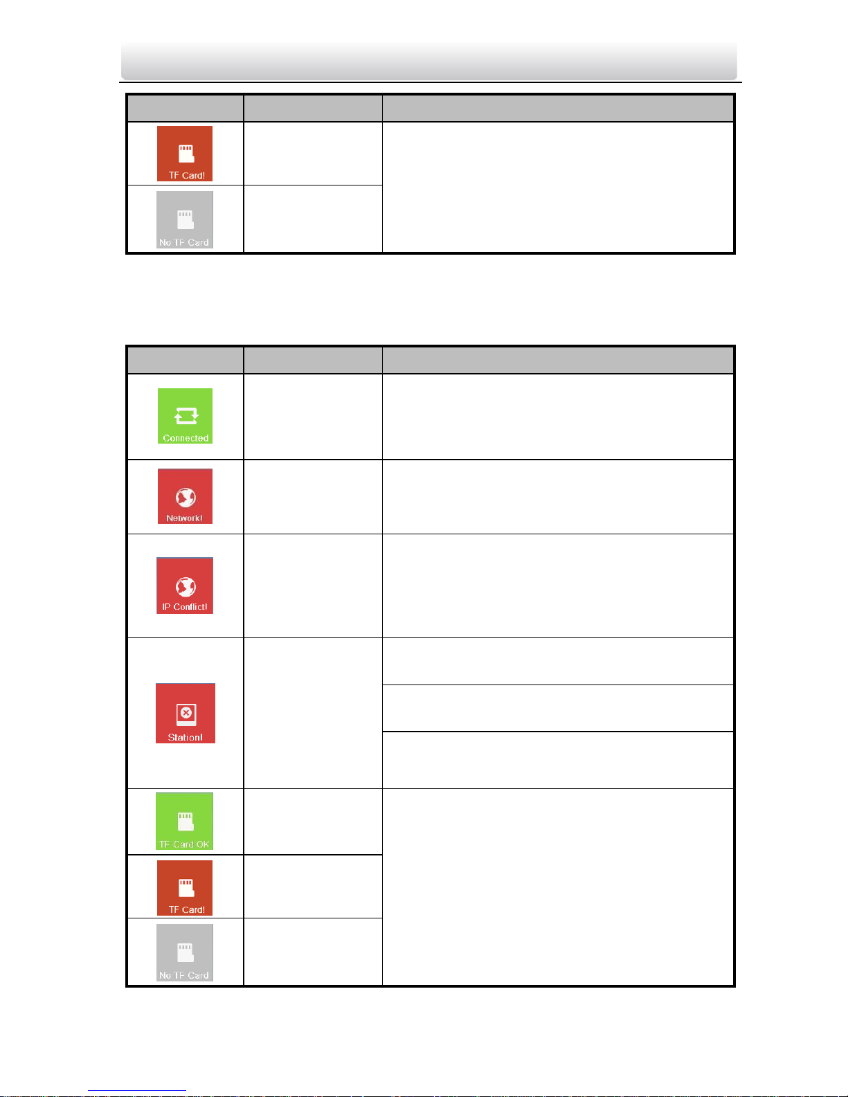
Video Intercom Indoor Station·User Manual
16
Icon
Definition
Description
Exception occurs
with the TF card.
No TF card is
inserted in the
indoor station.
7.2.4 Status of Indoor Extension
Table 7-2 Description of Status Icons
Icon
Definition
Description
Normal Status.
The communication between indoor station
and indoor extension is normal.
The indoor
extension is
offline.
Please check the network cable or Wi-Fi
connection.
The indoor
extension IP
address conflicts
with that of
other device.
Please check the IP address.
The indoor
extension has
not connected
to the indoor
station.
Invalid indoor station IP address. Set the indoor
station IP address.
Network of indoor station is not available.
Check the indoor station network connection.
The indoor extension number conflicts with
number of another indoor extension.
TF card is
inserted in the
indoor station.
Exception occurs
with the TF card.
No TF card is
inserted in the
indoor station.
Video Intercom Indoor Station·User Manual
17
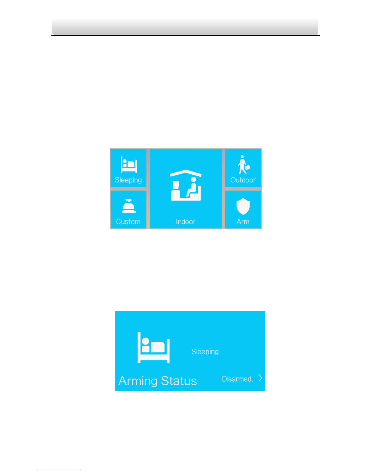
7.2.5 Arming Status
Purpose:
4 kinds of scene modes are supported by the indoor station: Sleeping Mode, Indoor
Mode, Outdoor Mode, and Custom Mode.
You can arm or disarm your room in each scene mode manually. When your room is in
the arming status, the arming status will display on the main interface of the indoor
station.
Arming Your Room
Steps:
1. Press the Arming Status tab to display the arming status interface.
Figure 9-1 Pressing Arm Tab
2. Press the Arm tab.
3. Enter the arm password to enable the arming status.
4. (Optional) Press a scene mode icon, and enter the arm password to change the scene
mode of the indoor station.
Example: After setting the arming status, press the Sleeping tab, and enter the arm
password. The indoor station changes to the arming status of the sleeping mode and
the interface will display as follow:
Figure 9-2 Sleeping Mode
Video Intercom Indoor Station·User Manual
18
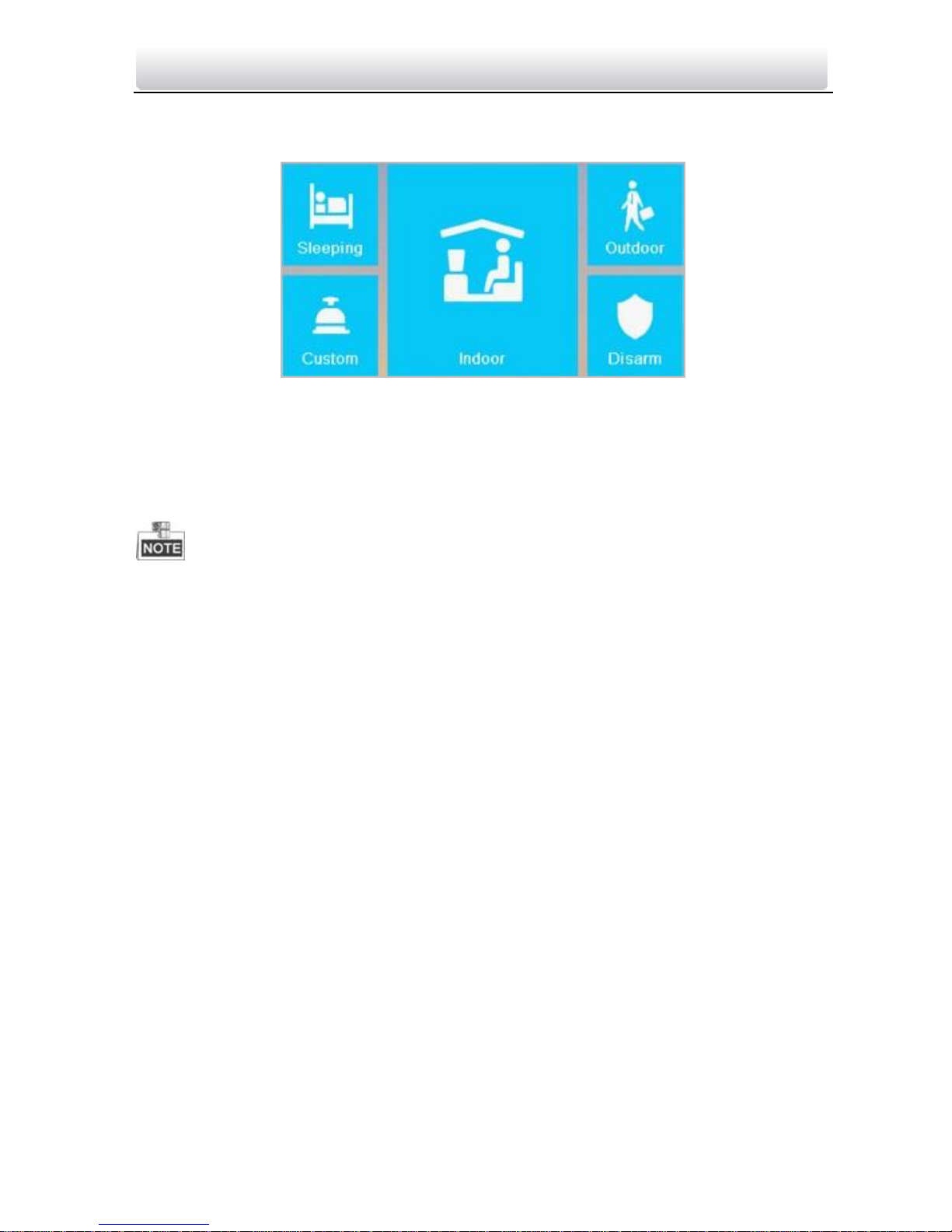
Disarming Your Room
1. Press the Arming Status tab to display the arming status interface.
Figure 9-3 Pressing Disarm Tab
2. Press the Disarm tab.
3. Enter the disarm password to enable the disarming status.
4. (Optional) Press a scene mode icon, and enter the disarm password to change the
scene mode of the indoor station.
Only one mode of arming can be set at one time. When you set another mode of
arming status, the former one is disarmed automatically.
If enabling the arming status successfully, you can hear a voice prompt “armed”, and
the corresponding arming status will display on the main interface.
If enabling the disarming status successfully, you can hear a voice prompt “disarmed”,
and the corresponding disarming status will display on the main interface.
The type III indoor station does not support this function.
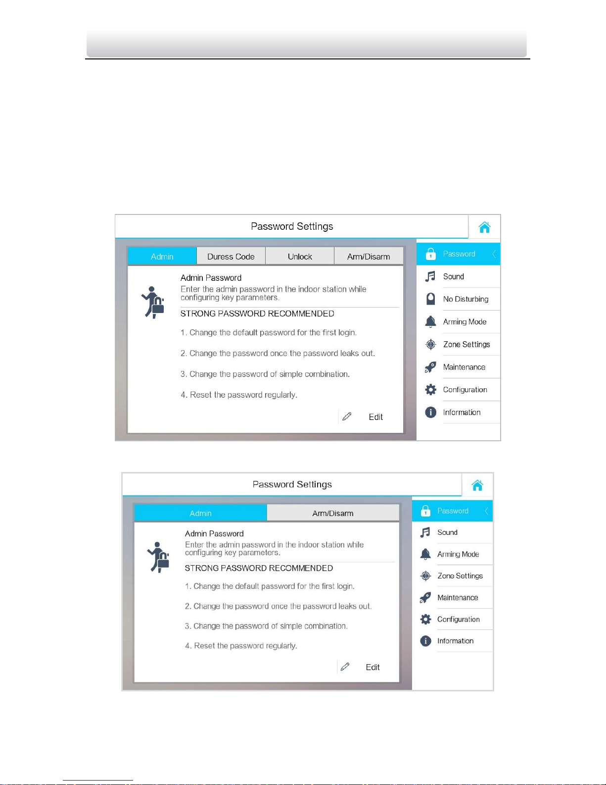
7.3 Indoor Station Settings
Purpose:
On the settings interface, you can set passwords (admin password, duress code, unlock
password, and arm/disarm password), set the device sound, set no disturbing schedule,
set the arming mode and zone, perform the system maintenance, set the configuration
settings, and view the device information.
7.3.1 Password Settings
Purpose:
You can edit the admin password (configuration password), duress code, unlock
password and arm/disarm password of the indoor station.
Video Intercom Indoor Station·User Manual
19
You can edit the admin password (configuration password) and arm/disarm password
of the indoor extension.
Enter admin password when configuring key parameters.
Enter duress code in the door station when the user is hijacked.
Enter unlock password in the door station when opening door of the building.
Enter arm/disarm password when arming/disarming the zone.
Steps:
1. Press the Settings tab on the touch screen to enter the password settings interface.
Figure 9-4 Password Settings Interface (Indoor Station)
Figure 9-5 Password Settings Interface (indoor Extension)
Video Intercom Indoor Station·User Manual
20
2. Press the Admin Password tab, Duress Code tab, Unlock Password tab, or
Arm/Disarm Password tab to enter corresponding interfaces.
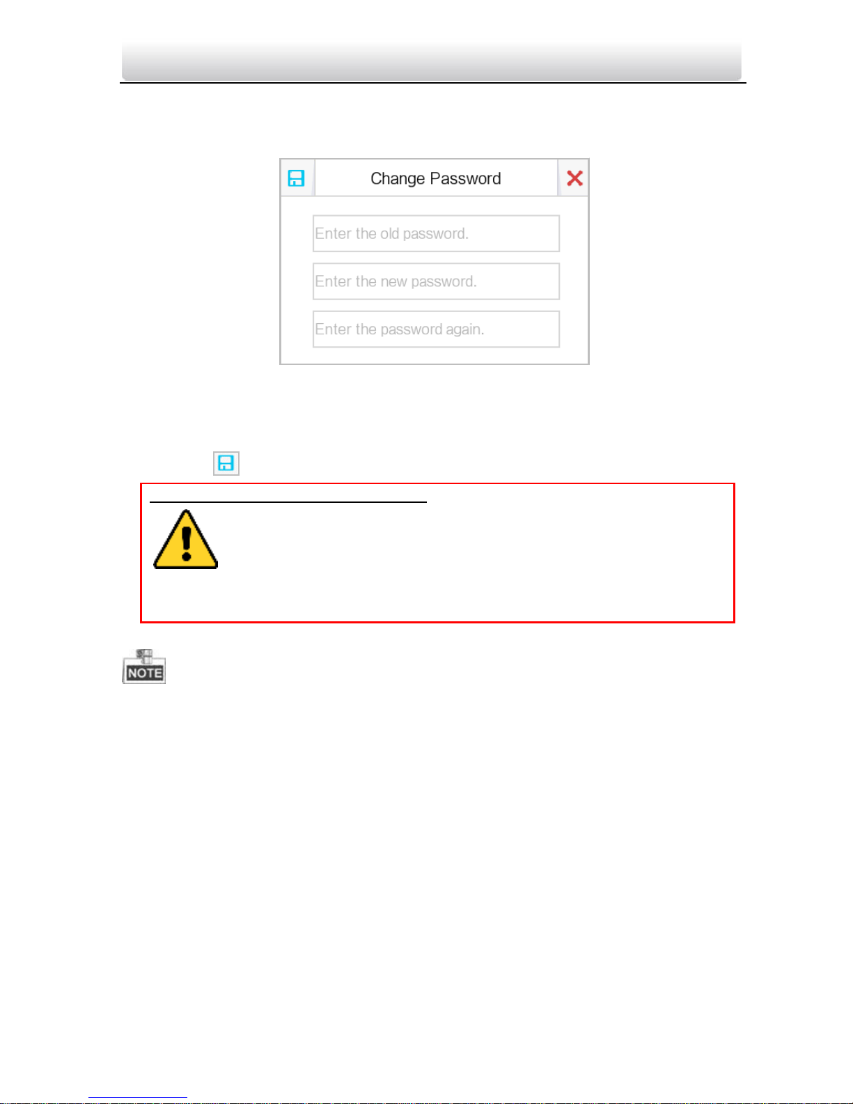
3. Press the Edit tab to pop up the password changing dialogue box.
Figure 9-6 Password Changing Interface
4. Enter the old password to change it
5. Enter the new password and confirm it.
6. Press the tab to save the settings.
The default admin password (configuration password) is 888999.
The default unlock password, arm/disarm password, and scene password are 123456.
The default duress code is 654321.
For Indoor Extension, only admin password and arm/disarm password are supported.
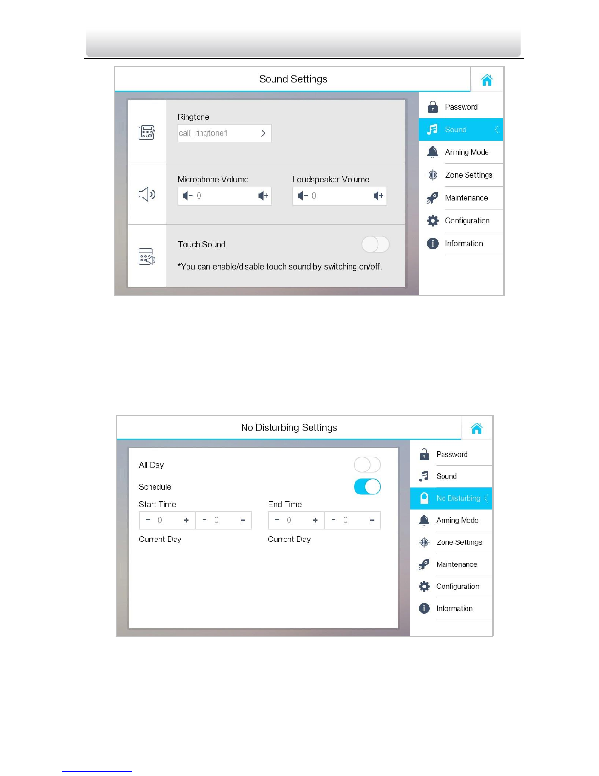
7.3.2 Sound Settings
Purpose:
You can set the ringtone, ring duration, call forwarding time, volume of microphone and
loudspeaker, enable/disable touch sound and auto-answer function on sound settings
interface.
Steps:
1. Get to the sound settings interface: Settings -> Sound Settings.
STRONG PASSWORD RECOMMENDED– We highly recommend you to create a
strong password of your own choosing (using a minimum of 8
characters, including at least three kinds of following categories: upper
case letters, lower case letters, numbers, and special characters) in
order to increase the security of your product. And we recommend
you reset your password regularly, especially in the high security system, resetting
the password monthly or weekly can better protect your product.

Video Intercom Indoor Station·User Manual
21
Figure 9-7 Sound Settings Interface (Indoor Station)
2. Set corresponding parameters.
Ringtone: There are 3 ringtones by default, and you can custom and import at most 4
ringtones via Batch Configuration Tool or VEZPRO Client Software.
Ring Duration: The maximum duration of indoor station when it is called without being
accepted. Ring duration ranges from 30s to 60s.
Call Forwarding (Time): The ring duration limit beyond which the call is automatically
forwarded to eh mobile phone designated by the resident. Call forwarding (time)
ranges from 0s to 20s.
Enable Auto-Answer: After enabling the auto-answer function, the visitor can leave
the voice message to the indoor station from the door station, the master station, or
the client software.
For indoor extension, it does not support the ring duration settings, call forwarding
settings, or auto-answer function.
Video Intercom Indoor Station·User Manual
22
Figure 9-8 Sound Settings Interface (Indoor Extension)
7.3.3 No Disturbing Settings
Purpose:
Two types of no disturbing mode can be configured: All day and Scheduled.
Steps:
1. Get to the no disturbing settings interface: Settings -> No Disturbing.
Figure 9-9 No Disturbing Settings Interface
2. Select no disturbing mode: All Day or Scheduled.
All Day:
 Loading...