

Vexve Hydrox Series, Hydrox8, Hydrox035BP, Hydrox2, Hydrox4 Installation, Operation And Maintenance Manual
...Page 1
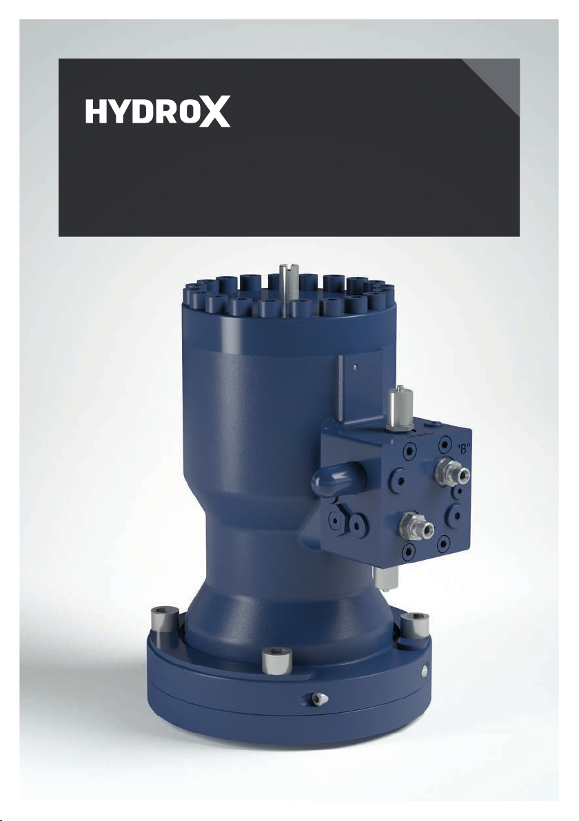
Hydrox hydraulic actuator
installation, operation and maintenance manual
Page 2

Contents
1. General 4
2. Actuator identification 5
2.1 Type code 6
3. Unloading and storage 7
3.1 Lifting the actuator 8
4. Functional description 9
4.1 Rotation direction 9
5. Actuator disassembly, installation and mechanical adjustment 10
5.1 Disassembly 11
5.2 Installation and angle adjustment 12
5.2.1 Ball valve 13
5.2.2 Butterfly valve 14
6. Commissioning and hydraulic adjustment 15
6.1 Commissioning 15
6.2.1. Maximum torques 16
6.2.2. Torque / Pressure tables 17
7. Maintenance 20
7.1 Oil change 20
2 3
www.vexve.com
Page 3
NOTE:
This manual must be read and its instructions must be followed when installing, operating
and/or performing maintenance on the actuator or its equipment.
These instructions are of general nature and do not cover all possible operating scenarios. For more
specific guidance on the installation, operation and maintenance of the actuator or its suitability for an
intended use, please contact the manufacturer.
Vexve Oy reserves the right to make alterations to these instructions.
Vexve Oy is not responsible for damages caused by incorrect transportation, handling, installation,
operation or maintenance. Furthermore, Vexve Oy is not responsible for damage caused by foreign
objects or impurities.
Warranty
Warranty according to Vexve Oy’s “General terms and conditions of sale”.
The warranty covers manufacturing and material faults. The warranty does not apply to damages
caused by inappropriate installation, operation, maintenance, or storage ie. these instructions must be
followed for the warranty to apply. Vexve Oy requires that any faulty products under warranty are to be
returned to the factory for inspection. Only after the product has been found faulty, Vexve Oy can grant
compensation.
Please refer to Vexve Oy’s “General terms and conditions of sale” for detailed warranty clauses. The
document is available from the manufacturer
Warnings and symbols
Ignoring the warnings and symbols may lead to serious injury or equipment damage. Persons authorized
to use the equipment must be familiar with the warnings and instructions.
Appropriate transportation, storage and installation as well as careful commissioning are essential to
ensure faultless and stable operation.
The following symbols are used in this manual to draw attention to actions essential to ensure the proper
use and safety of the device.
Meaning of the symbol: NOTE
The NOTE symbol is used for actions and functions that are essential for the proper use of
the device. Ignoring this symbol may have harmful consequences.
Meaning of the symbol: WARNING
The WARNING symbol is used for actions and functions that, if carried out incorrectly, may
lead to injury or equipment damage.
Page 4
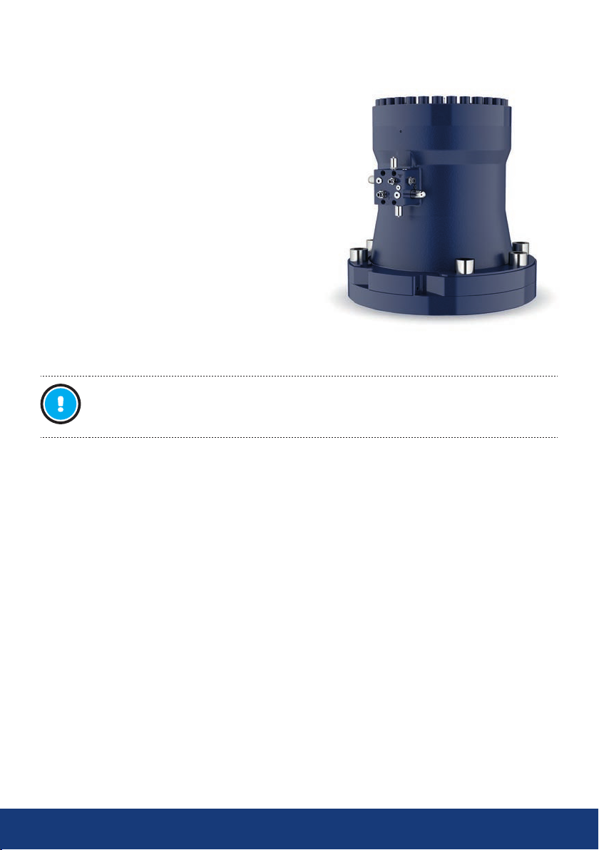
1. General
Vexve Oy’s Hydrox hydraulic actuator is suitable
for even the most challenging installation sites
and conditions. Specifically designed for district
heating and district cooling applications and
to operate seamlessly with Vexve and Naval
ball and butterfly valves, the Hydrox hydraulic
actuator is the perfect solution for underground
installation providing easy and reliable operation
with maximum safety at all times.
NOTE:
When intending to use the actuator with valves from other manufacturers than Vexve Oy
please contact Vexve Oy to ensure its suitability.
For detailed technical information including dimensions and weights, torques etc. please refer to
Hydrox Product catalogue or data sheets (www.vexve.com).
4 5
www.vexve.com
Page 5
2. Actuator identification
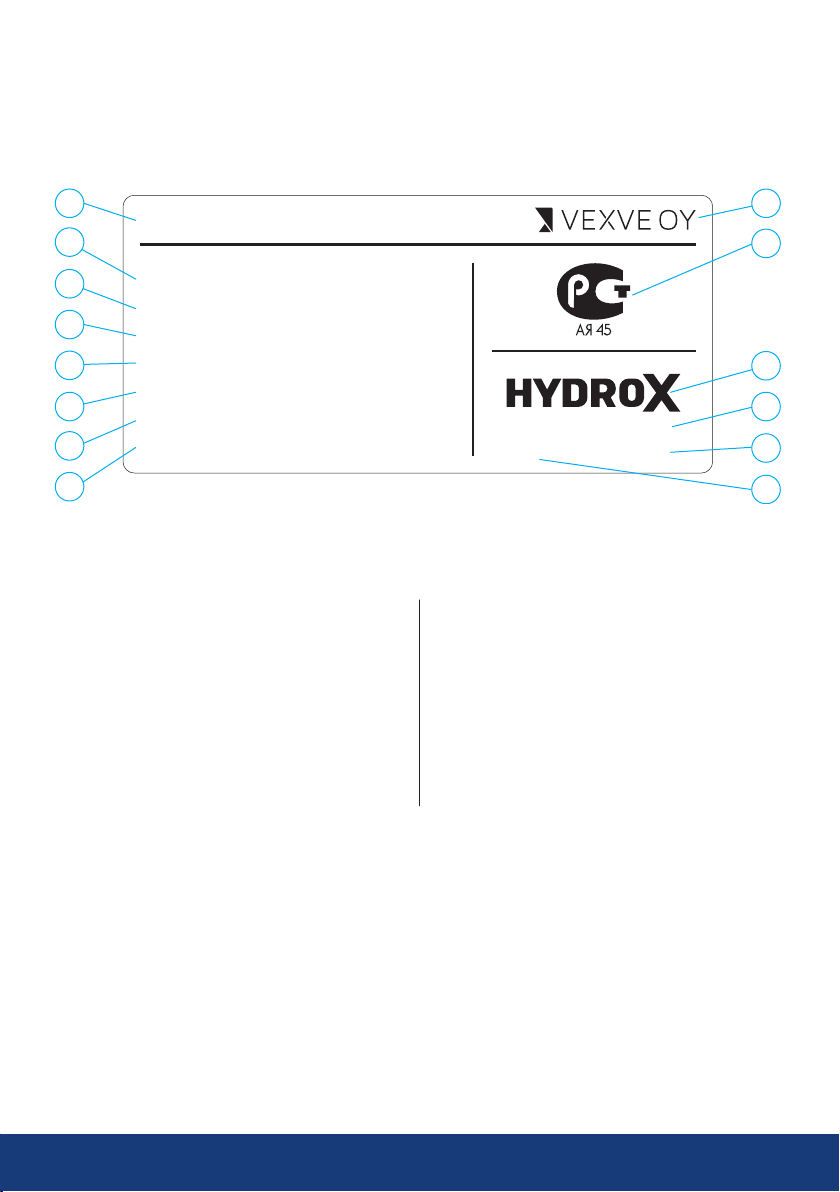
The identification plate locates at the actuator body. It has the following information:
1
Type: Hydrox 4
2
3
4
5
6
7
8
1. Actuator type
2. Product no
3. Nominal torque
4. Nominal operating pressure
5. Max. operating pressure
6. Ambient temperature
7. Displacement
8. Dry weight
Product no:
Nominal torque:
Nominal operating pressure:
Max. operating pressure:
Ambient temperature:
Displacement:
Dry weight:
80100416040
4000 Nm
135 bar
200 bar
-25…80 ºC
0,8 l
63 kg
Figure 1. Identification plate.
9. Producer
10. Russian valve certification
11. Trademark
12. Manufacturer
13. Producer’s website
14. Manufacturing date
By Tasowheel Gears Oy
0415 - www.vexve.com
9
10
11
12
13
14
Page 6
2.1 Type code
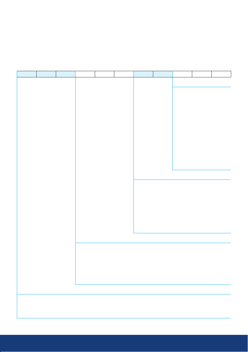
Type codes of Hydrox actuators consist of eleven (11) digits as described in the table below:
Example: 80100416040
8 0 1 0 0 4 1 6 0 4 0
Bore size
011 = [] 11 mm
014 = [] 14 mm
016 = [] 16 mm
019 = HEX-19
020 = [] 20 mm
035 = Ø 35 mm
040 = Ø 40 mm
050 = Ø 50 mm
060 = Ø 60 mm
070 = Ø 70 mm
090 = Ø 90 mm
100 = Ø 100 mm
120 = Ø 120 mm
140 = Ø 140 mm
Flange size (acc. ISO5211)
07 = F07
10 = F10
12 = F12
14 = F14
16 = F16
25 = F25
30 = F30
35 = F35
40 = F40
Actuator size
035 = Hydrox By-pass
002 = Hydrox 2
004 = Hydrox 4
008 = Hydrox 8
016 = Hydrox 16
032 = Hydrox 32
064 = Hydrox 64
Product family
800 = Hydrox actuators with connection block
801 = Hydrox actuators with control block
802 = Hydrox ByPass actuators with connection block
803 = Hydrox ByPass actuators with control block
6 7
www.vexve.com
Page 7
3. Unloading and storage
Check that the content of the delivery is as
ordered. Check that the actuator and related
equipment have not been damaged during
transportation.
Store the actuator carefully before installation,
preferably in a well-ventilated, dry place, on a
shelf or a wooden grid to protect it from rising
damp.
Protect bare metal surfaces, shaft parts, and
flange surfaces with anti-corrosive agent before
storage.
The actuator must be transported to the
installation site in a sturdy package. Do not
remove any protectors before installation.
Protect the actuator from dust and other
impurities.
NOTE:
If the actuator is delivered preassembled with a valve refer to the
handling and lifting instructions of
the valve.
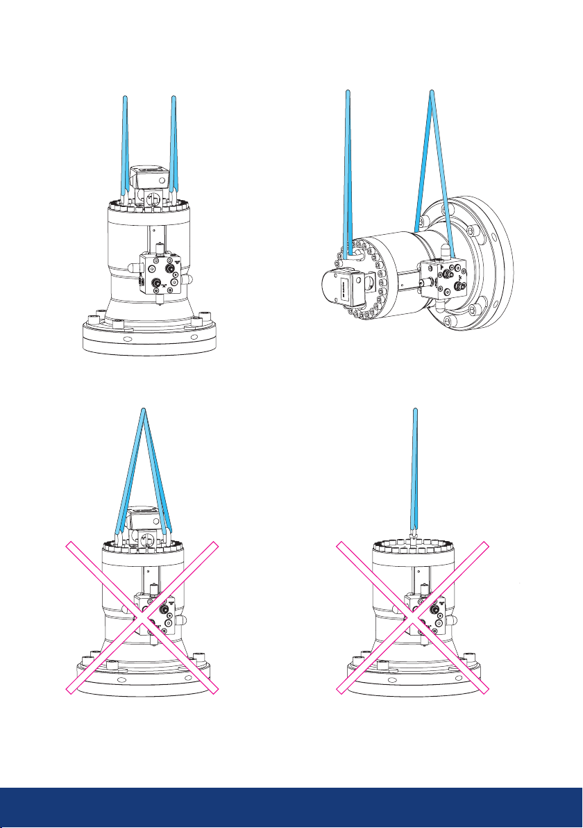
WARNING:
It is forbidden to lift the actuator
by the control block! Make sure
that lifting ropes or chains do
not even touch the control block
during lifting.
Packaging:
Vexve’s products are protected during
transportation with special packaging. The
packaging consists of environmentally friendly
materials that are easy to sort and recycle.
Recycling the packaging materials at designated
waste collection points is recommended.
The following packaging materials are used:
wood, cardboard, paper, and polyethylene
sheets.
Recycling and disposal
Nearly all parts of the actuator are made of
recyclable materials. The material type is marked
on most parts. Separate recycling and disposal
instructions are available from the manufacturer.
The actuator can also be returned to the
manufacturer for recycling and disposal against
a fee.
Take the weight of the actuator and valve into
account when handling them.
When delivered, the actuator is in the open
position. During storage, the actuator must also
be in the open position.
Maximum recommended storage time is two
years. If the actuator is stored for more than two
years, it should be operated and cleaned yearly.
Page 8
3.1 Lifting the actuator
8 9
www.vexve.com
Page 9
4. Functional description
The oil pressure which is supplied through connections “A” and “B” causes a rotary movement on the
actuator shaft. The linear movement of the piston is converted into a rotary movement by means of
multiple gears
4.1 Rotation direction
See Figure 2
The rotation direction of the actuator shaft depends on which connection the pressure is applied:
· If the pressure is applied to the connection “A” the actuator shaft rotates clockwise closing the valve.
· If the pressure is applied to the connection “B” the actuator shaft rotates counterclockwise opening the
valve.
There is an indicator slot on the top of the actuator shaft so it is easy to notice which direction the shaft
is rotating. When the slot is parallel to the front face of control block, valve is closed. When the slot is
perpendicular to the front face of the control block, valve is open, see Figure 3.
B*
A*
B
A
*) connection block
Pressure on A: valve closes.
Pressure on B: valve opens
Figure 2.
OPEN
CLOSED
Figure 3.
Indicator slot tells if the valve is open or closed
Page 10
5. Actuator disassembly, installation and
mechanical adjustment
NOTE:
Avoid removing the actuator from the valve. The actuator has been calibrated at the
factory to ensure that the valve is tight. If the actuator is removed, it may have to be recalibrated.
Vexve Oy accepts responsibility only for actuators installed by Vexve.
Refer to the Hydrox product catalogue or data sheets (www.vexve.com) for maximum
permissible diameter of shaft and shaft intrusion. Actuator is equipped with only one key
way so it is not possible to change its installation position on the valve
WARNING:
All couplings and hoses of the actuator, and equipment connected to it, must always be
kept clean since impurities might cause failures in the operation of the system.
If the actuator is equipped with quick couplings and fast and significant changes in
temperature are possible, thermal expansion of the hydraulic oil must be taken into
consideration.
The actuator may not be removed or dismantled if the valve is pressurized! It is
recommended to use the special actuator removal tools!
Incorrect disconnection may cause serious personal injuries as well as malfunction and
damage to the equipment. Extreme caution must be exercised during the disconnection!
Do not use too high torques to operate the valve. Too high torques can damage the valve
or the actuator! See tables 1 and 2 in chapter 6.2.1 for maximum torques.
10 11
www.vexve.com
Page 11
5.1 Disassembly
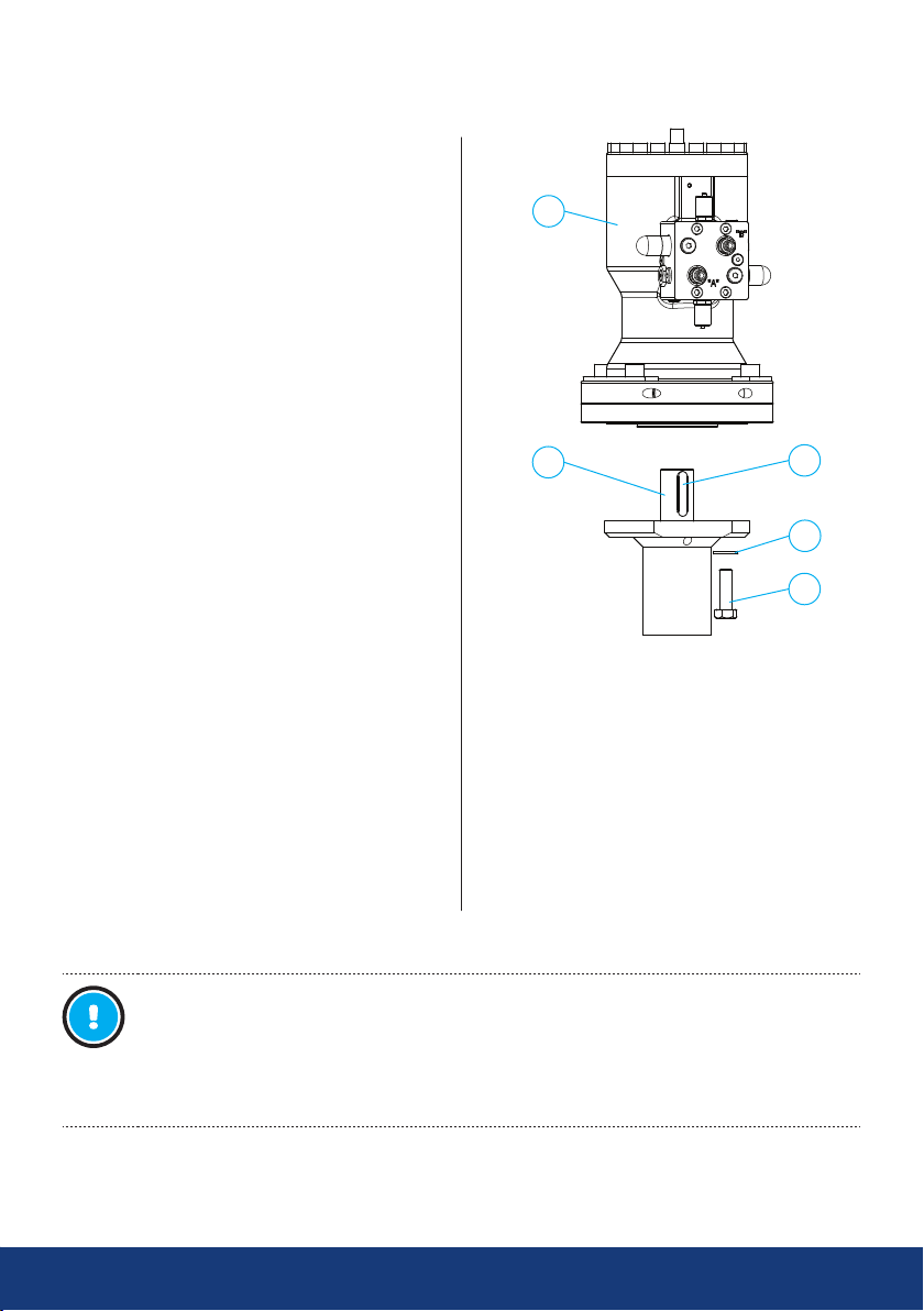
Part numbers mentioned in this chapter refer to
the figure 4.
1. Ball valves: Turn the valve to the open
position (counter-clockwise) before
removing the actuator (1).
Butterfly valves: Turn the valve to the
close position (clockwise) before removing
the actuator (1).
Valve opens by pumping hydraulic oil into
connection “B” and closes when hydraulic
oil is pumped into connection “A”. Use a
hand pump or a hydraulic power unit
2. Turn the actuator slightly backwards to
release forces between the valve and
the actuator in order to make it easier to
remove the actuator:
Ball valves: Turn the actuator slightly
towards the close position (clockwise)
by pumping a little hydraulic oil into
connection “A” until pressure level is low
Butterfly valves: Turn the actuator slightly
towards open position (counter-clockwise)
by pumping a little hydraulic oil into
connection “B” until pressure level is low
3. Remove any position indicator if used
4. Remove the attachment bolts (2) of the
actuator and remove the actuator (1)
Reinstallation instructions for ball valves see
chapter 5.2.1 steps 1-5 and for butterfly valves,
see chapter 5.2.2 steps 1-5.
1
4
Figure 4. Assembly
5
3
2
NOTE:
If working in potentially explosive atmosphere all related safety and work instructions
must be followed.
Any tools or working methods generating sparks or extensive heat are not allowed
without written permission from responsible personnel.
Page 12
5.2 Installation and angle adjustment
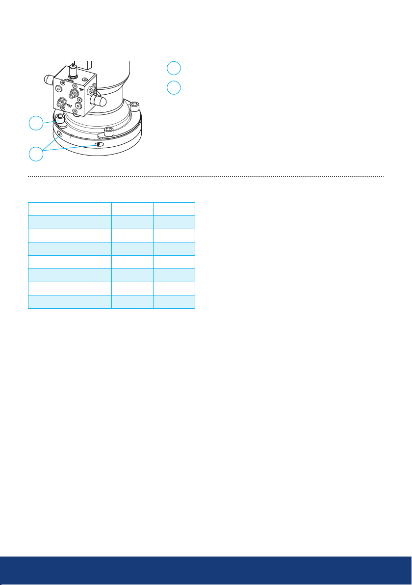
1 Fastening screws
2
Angle adjustment screws
1
2
Figure 5. Angle adjustment
Installation tightening torques [Nm]
Hydrox model Screws 1 Screws 2
Hydrox035BP 25 8
Hydrox2 170 10
Hydrox4 170 10
Hydrox8 350 10
Hydrox16 350 10
Hydrox32 1200 20
Hydrox64 2400 20
Torques suitable for default screws
12 13
www.vexve.com
Page 13
5.2.1 Ball valve
If the actuator is already installed to the valve, you can skip the points 1-5
NOTE:
If working in potentially explosive atmosphere all related safety and work instructions
must be followed.
Any tools or working methods generating sparks or extensive heat are not allowed
without written permission from responsible personnel.
Please check the actuator’s position before mounting it on the valve.
Please also check that the top flange and the valve stem are perpendicular to each other
and that there are no impurities between the actuator and the valve. Impurities or wrong
position between the top flange and valve stem might damage the actuator.
Installing the actuator
Part numbers refer to the figure 4
1. Vexve ball valves are delivered from the factory in the open position. If the valve has been operated
so that it is in some other position, turn the valve to the open position.
2. Check that the valve stem (4) is intact and clean. Check also that the key (5) of the valve stem is
properly in its groove
3. Turn the actuator to the open position
4. Install the actuator on the valve. Note that the actuator is equipped with one key way so it is not
possible to change its installation position on the valve. The key way of the actuator must fit the
stem easily and you must not force it in its place
Grease the attachment screws (2) of the actuator. Put all the washers (3) and the attachment screws (2)
first loosely in their places and finally tighten them up
Angle adjustment
NOTE:
Adjust the angle so that it exceeds the actual OPEN and CLOSE positions of the valve
evenly.
Part numbers refer to the figure 5
5. Open the fastening screws (1). Adjust the correct OPEN position by loosening the other and
tightening the other angle adjustment screw (2). Tighten the fastening screws (1)
6. Turn the valve slightly towards the close position and then back to the open position against the
limit. Check if the OPEN position is correct. If it is not correct, repeat the steps 6 and 7
7. Check that the valve opens and closes correctly
Page 14
5.2.2 Butterfly valve
If the actuator is already installed to the valve, you can skip the points 1-5
NOTE:
If working in potentially explosive atmosphere all related safety and work instructions
must be followed.
Any tools or working methods generating sparks or extensive heat are not allowed
without written permission from responsible personnel.
Please check the actuator’s position before mounting it on the valve.
Please also check that the top flange and the valve stem are perpendicular to each other
and that there are no impurities between the actuator and the valve. Impurities or wrong
position between the top flange and valve stem might damage the actuator.
Installing the actuator
Part numbers refer to the figure 4
1. Vexve butterfly valves are delivered from the factory in the close position. If the valve has been
operated so that it is in some other position, turn the valve to the close position.
2. Check that the valve stem (4) is intact and clean. Check also that the key (5) of the valve stem is
properly in its groove
3. Turn the actuator (1) to the close position
4. Install the actuator on the valve. Note that the actuator is equipped with one key way so it is not
possible to change its installation position on the valve. The key way of the actuator must fit the
stem easily and you must not force it in its place
5. Grease the attachment screws (2) of the actuator. Put all the washers (3) and the attachment
screws (2) first loosely in their places and finally tighten them up
Angle adjustment
NOTE:
Adjust the angle so that the disc doesn’t exceed its correct CLOSE position. If the disc
turns over the correct CLOSE position, it will damage the disc seal.
Part numbers refer to the figure 5
6. Tighten the fastening screws (1). Adjust the correct CLOSE position by loosen the other and
tightening the other angle adjustment screw (2). Tighten the fastening screws (1)
7. Turn the valve slightly towards the open position and then back to the close position against the
limit. Be sure not to turn the disc too much towards the CLOSE position, it will damage the disc
seal. Check if the CLOSE position is correct. If it is not correct, repeat the steps 6 and 7
8. Check that the valve opens and closes correctly
14 15
www.vexve.com
Page 15
6. Commissioning and hydraulic adjustment
6.1 Commissioning
Connect the hydraulic hoses to connections “A” and “B”. Refer to 4.1 to ensure turning direction of
actuator in relation to connections.
NOTE:
Refer to manufacturer manual of
the control unit to ensure proper
commissioning and operation with
control unit in use.
6.2 Hydraulic adjustment
NOTE:
Written permission from Vexve Oy
is required to perform hydraulic
adjustment.
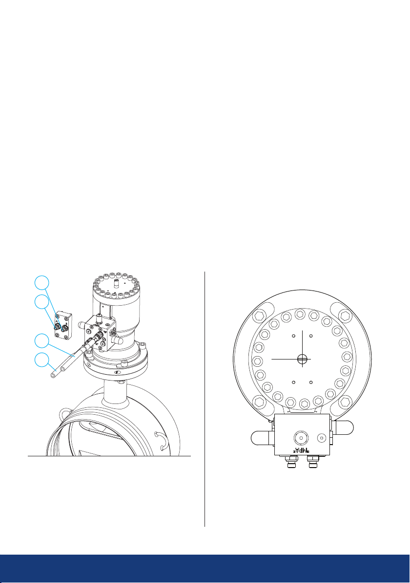
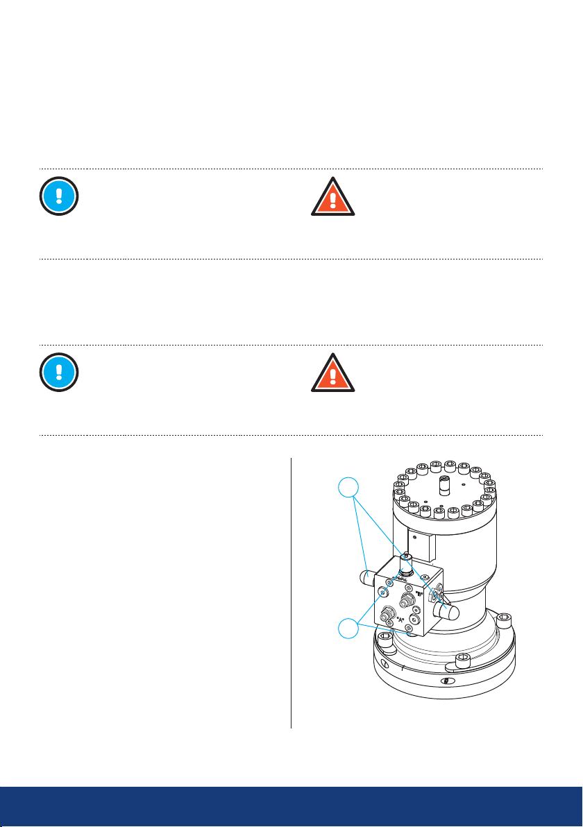
See Figure 6
The maximum hydraulic operating pressure can
be adjusted (and limited) by the control block
(if equipped) of the actuator for both directions
separately: By turning the adjustment screw
(1) clockwise the maximum hydraulic operating
pressure increases and vice versa it decreases
by turning the screw counterclockwise.
If needed, increase the maximum operating
pressure, maximum allowed operating pressure
is 200 bars.
A pressure gauge can be attached to the control
block to monitor the hydraulic pressure while
adjusting. The pressure gauge can be mounted
on connections (2) “MPA” for connection “A” and
“MPB” for connection “B”.
WARNING:
Before first operation the hydraulic
system has to be cleaned and bled
carefully so that there is no air in
the hydraulic system.
WARNING:
It is strictly prohibited to exceed
the torques in the tables 1 and 2!
Too high torques can damage the
valve or the actuator!
1
2
Figure 6. Hydraulic adjustment
Page 16
6.2.1. Maximum torques
NOTE:
Actuators that are equipped with control block have been preadjusted to the correct
pressure / torque level.
Actuators with connection block do not include pressure limiter.
Therefore pay extra attention when comissioning and using them.
It is prohibited to exceed the torques in tables 1 and 2!
Butterfly valves
DN Max torque [Nm] Hydrox model Max pressure [bar]
300 1560 Hydrox2 110
350 1820 Hydrox2 130
400 2990 Hydrox4 110
450 6000 Hydrox8 100
500 6370 Hydrox8 110
600 9360 Hydrox8 165
700 14300 Hydrox16 125
750 18000 Hydrox16 155
800 20800 Hydrox16 180
For sizes DN 900–1400 please contact the manufacturer
Table 1. Maximum torques of Vexve butterfly valves and corresponding pressures of actuators
16 17
www.vexve.com
Page 17
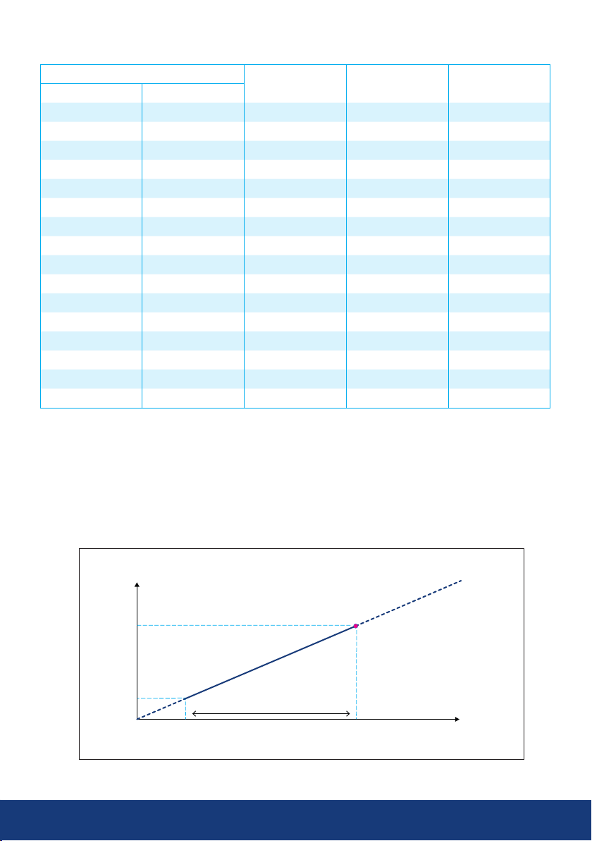
Ball valves
DN
RB FB
50 40 Hydrox035BP 70 27
65 50 Hydrox035BP 85 33
80 65 Hydrox035BP 130 50
100 80 Hydrox035BP 250 95
125 100 Hydrox2 390 25
150 125 Hydrox2 750 50
200 150 Hydrox2 1200 80
250 200 Hydrox2 2500 170
300 250 Hydrox4 5000 170
350 300 Hydrox4 5000 170
400 350 Hydrox8 6500 110
500 400 Hydrox8 12000 200
600 500 Hydrox8 12000 200
700 600 Hydrox16 18000 155
800 700 Hydrox32 28000 120
800 Hydrox64 37500 105
Hydrox model Max torque [Nm] Max pressure [bar]
Table 2. Maximum torques of Vexve ball valves and corresponding pressures of actuators
6.2.2. Torque / Pressure tables
520
350
Torque (Nm)
78
0
0
Recommended pressure range
30
Operating pressure (bar)
By-pass
Nominal
pressure / torque
135
*
200
Page 18
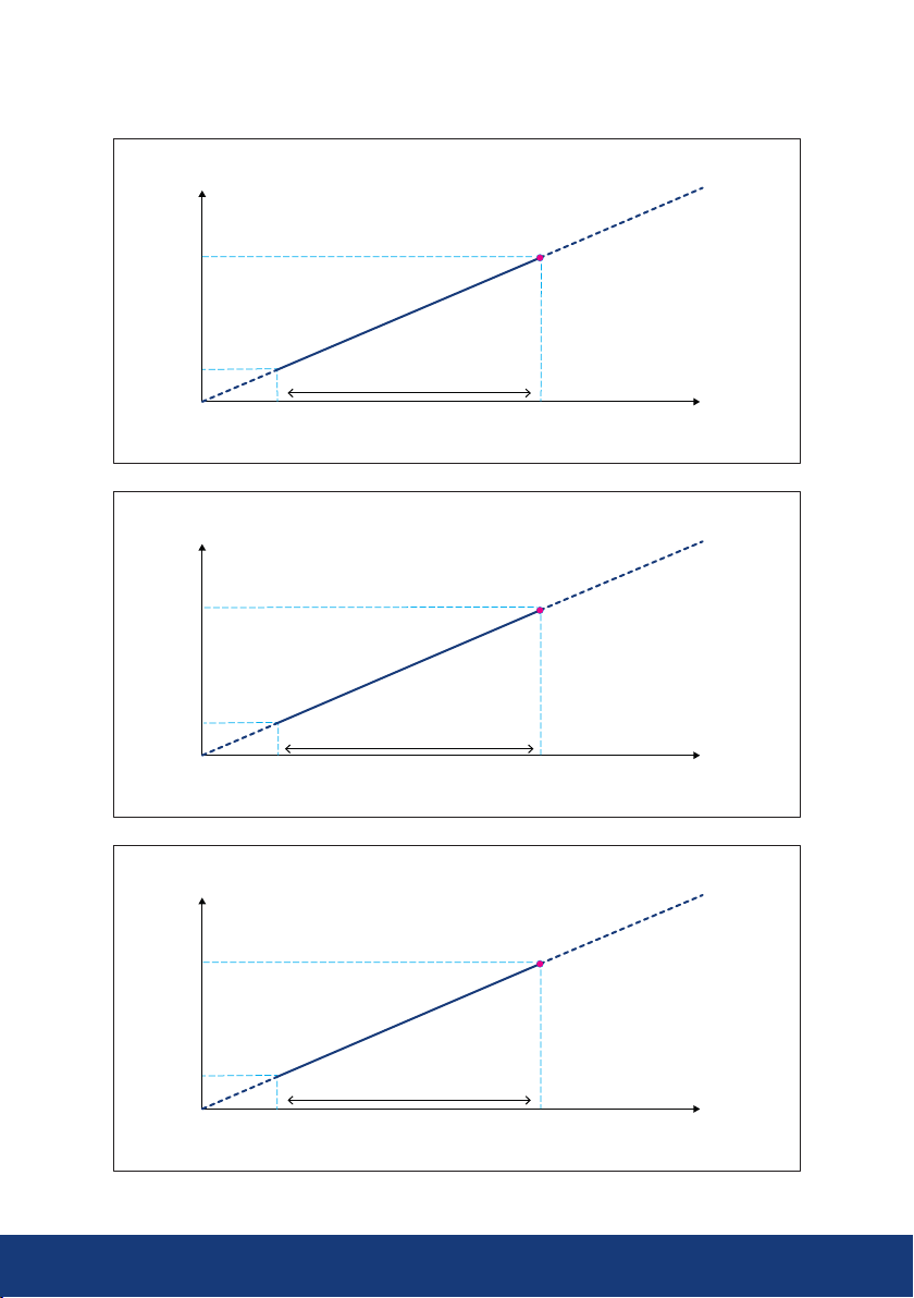
3000
2000
Torque (Nm)Torque (Nm)Torque (Nm)
435
5900
Hydrox2
*
Nominal
pressure / torque
Recommended pressure range
0
0
30
135
Operating pressure (bar)
200
Hydrox4
4000
890
Recommended pressure range
Nominal
pressure / torque
0
0
30
135
Operating pressure (bar)
Hydrox8
11800
8000
1780
Recommended pressure range
0
0 13530 200
Operating pressure (bar)
Nominal
pressure / torque
200
18 19
www.vexve.com
Page 19
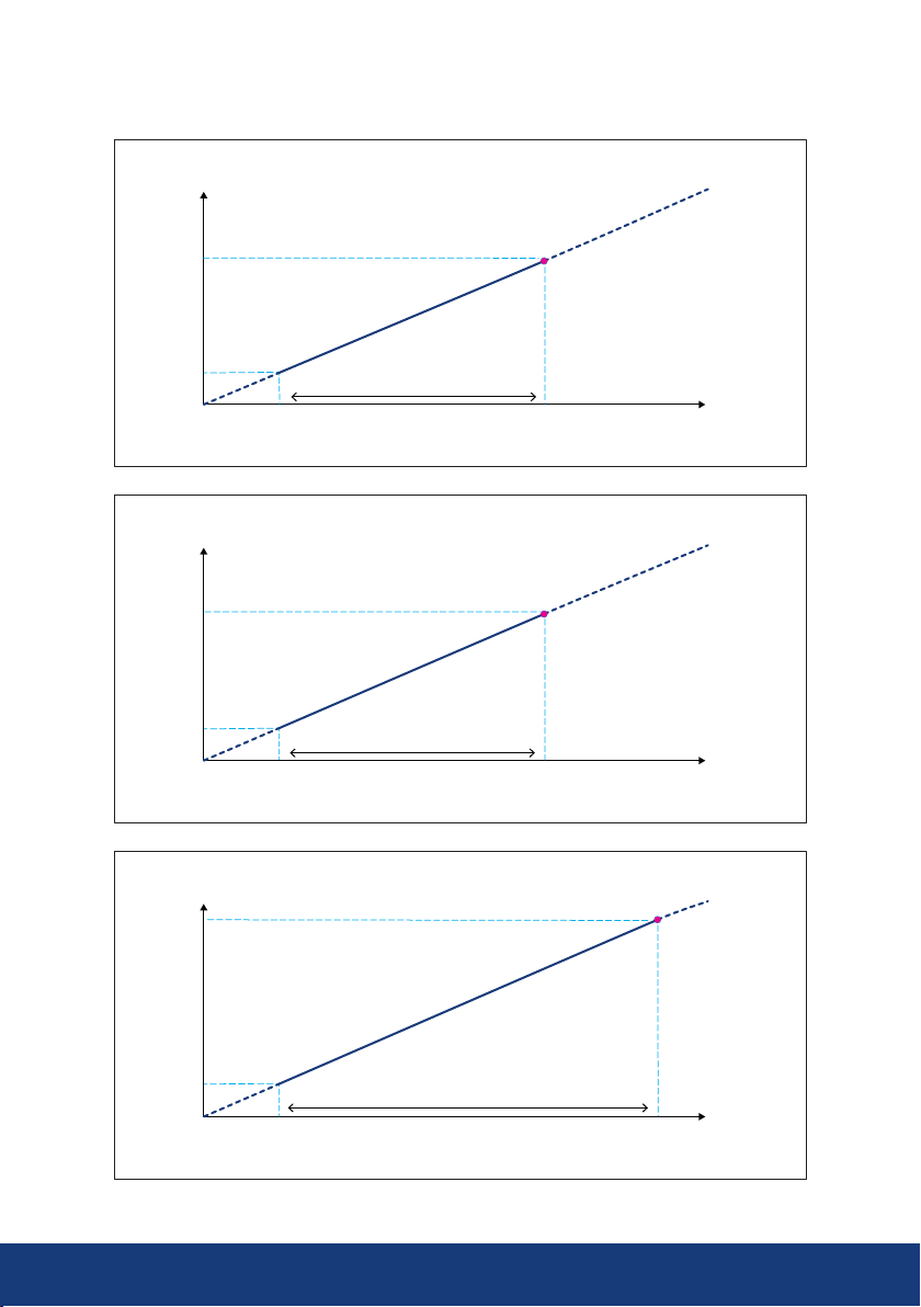
24000
Hydrox16
16000
Torque (Nm)Torque (Nm)Torque (Nm)
3560
Recommended pressure range
Nominal
pressure / torque
0
0 13530 200
Operating pressure (bar)
Hydrox32
47000
32000
7110
Recommended pressure range
Nominal
pressure / torque
0
0 13530 200
Operating pressure (bar)
Hydrox64
70000
64000
Nominal
pressure / torque
10700
Recommended pressure range
0
0 18030 200
Operating pressure (bar)
Page 20
7. Maintenance
Hydrox actuators need only little maintenance.
The correct choice of valve and actuator combination as well as careful installation, commissioning and
use, significantly reduce any need for maintenance.
WARNING:
When the valve is installed in the line, also the surface temperature of the actuator may
be dangerously high. Protect yourself against burns.
If working in potentially explosive atmosphere all related safety and work instructions
must be followed.
Any tools or working methods generating sparks or extensive heat are not allowed
without written permission from responsible personnel.
We recommend checking the following periodically:
Check that the actuator is free from oil leaks, and carefully tighten if any leakages occurred.
To ensure long-term operational reliability, even when seldom used (around ten times a year or less), we
recommend the following:
Approximately six months after commissioning and then once a year, check the functionality of the
actuator, inspect the actuator for oil leaks, and ensure the tightness of the fastening screws between
actuator and valve.
7.1 Oil change
Oil changes are necessary and depend on size of the system. Under clean conditions, it is recommended
that the condition of the oil is inspected approximately every two years and that the oil is replaced at every
second inspection. If dirty/low-quality oil is used, oil changes are necessary at shorter intervals. Because
the small oil volume in part-turn actuators compared to the volume in the pipework, there is no oil change
during the operating cycles. Because of this, it is recommended to change the hydraulic oil so that the oil
changes also inside the part-turn actuator and hoses not only in the hydraulic pump.
20 21
www.vexve.com
Page 21

Notes
Page 22

22 23
www.vexve.com
Page 23

Page 24

Vexve Oy
Pajakatu 11
FI-38200 Sastamala
Finland
Riihenkalliontie 10
FI-23800 Laitila
Finland
Tel. +358 10 734 0800
[email protected] www.vexve.com
1/2018 - All rights reserved
www.vexve.com
 Loading...