

Vexta SMK0A-*A Series, SMK2 Series, SMK0A-*B Series, SMK014A-A, SMK014A-B Operating Manual
...
■
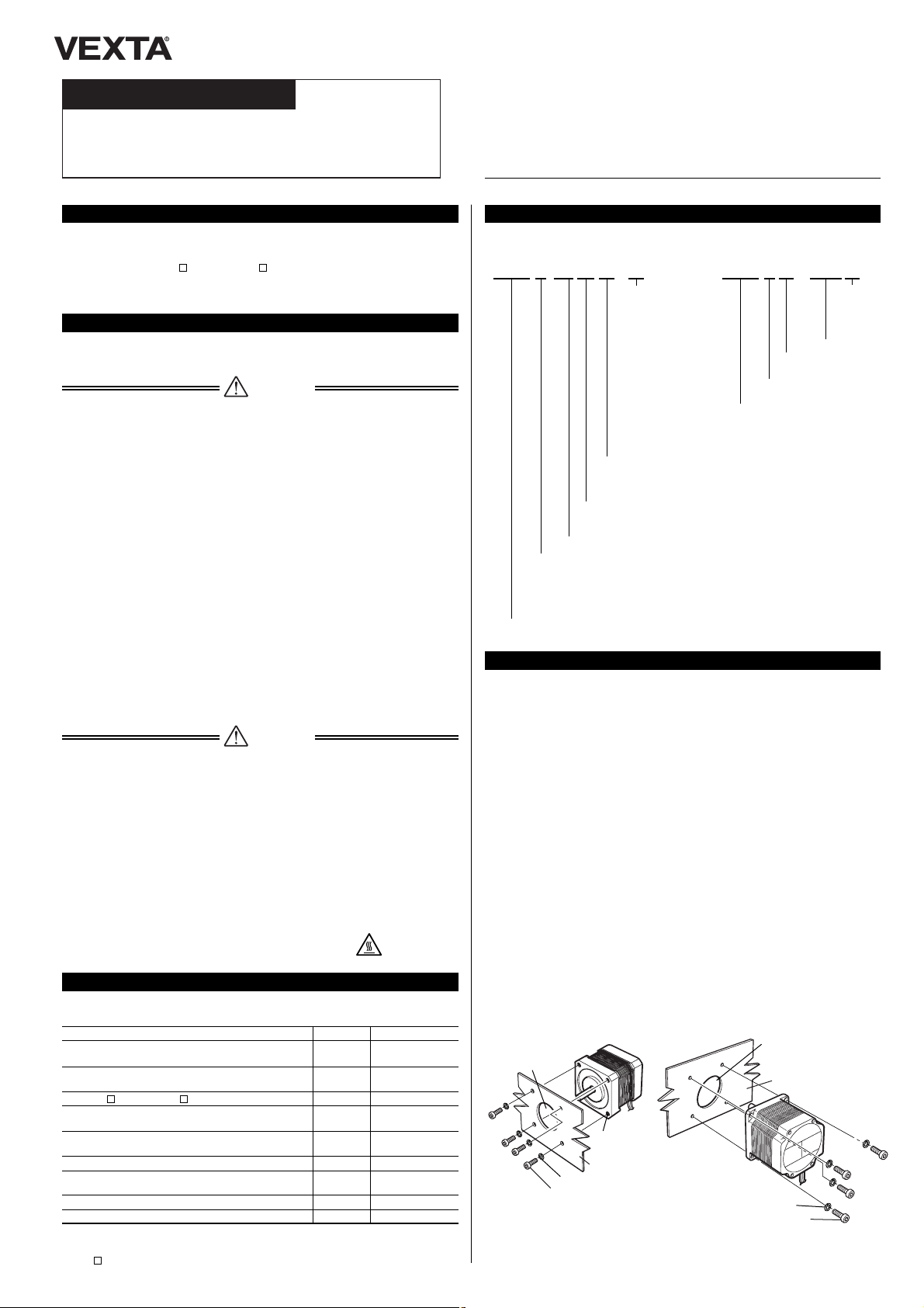
Method of installation
Install the motor on a smooth metallic plate offering a high resistance to vibration and excellent
heat-conductive properties.
●
Round shaft type
Using the four installation holes (or tapped holes) located on the motor's installation surfaces,
secure the motor with four bolts (not provided).
The motor's mounting pilot on the motor-installation hole should be inserted into the mountingpilot holder, which is countersunk or drilled through.
Low-Speed Synchronous Motor
SMK Series
OPERATING MANUAL
Thank you for purchasing an ORIENTAL MOTOR product.
This Operating Manual describes product handling procedures and safety precautions.
●
Please read it thoroughly to ensure safe operation.
●
Always keep the manual where it is readily accessible.
Only qualified personnel should work with the product.
This product is designed for incorporation in general industrial machinery, and must not be used
for another purpose. ORIENTAL MOTOR Co., Ltd. is not responsible for any damage caused
through failure to observe this warning.
This product is UL-recognized (impedance-protected ), and has made self-declaration of the
CE marking (the Low-Voltage Directive). (This does not apply to the SMK014A-A ,
SMK014A-B, SMK014MA-A, SMK014MA-B, SMK014K-A, SMK014K-B,
SMK014K-AA , SMK0A- A and SMK0A- B.)
■
Installation conditions
Overvoltage category
II
, Pollution degree 2, Class Iequipment
Introduction
The precautions described below are intended to ensure the safe and correct use of the product, and to prevent the customer or others from exposure to the risk of injury.
Read the body of the text based on a sufficient understanding of its importance.
Safety precautions
Warning
●
SMK0 type
●
SMK2, SMK5 type
Failure to observe the warnings contained herein may result in a situation leading to serious
injury or death.
●
Do not use the product in explosive or corrosive environments, in the presence of flammable
gases, locations subjected to splashing water, or near combustibles. Doing so may result in
fire, electric shock or injury.
●
Qualified personnel are required for the installation, connection, operation and inspection of
this product. Failure to do so may result in fire, electric shock or injury.
●
Be sure to turn off the power before installing, connecting or inspecting this product. Failure
to do so may result in electric shock.
●
Install the motor in the enclosure to avoid contact with the hands, or provide sufficient grounding. Failure to do so may result in electric shock or injury.
●
Connect this product securely and accurately, according to the connection diagrams. Failure
to do so may result in fire or electric shock.
●
Be sure to insulate the connection terminals of the capacitor and external resistor. Failure to
do so may result in electric shock.
●
Do not forcibly bend, pull or pinch the motor cable. Doing so may result in fire or electric
shock.
●
In case of power failure, be sure to turn off the power. Failure to do so may cause the motor
to start suddenly when the power is restored, and could result in injury or damage to the
equipment.
●
If this product is used in an elevator application, be sure to provide a measure for the position retention of moving parts. The motor loses its retentiveness when the power is turned off.
Failure to provide such a measure may cause the moving parts to fall off, resulting in injury
or damage to the equipment.
●
Do not touch the connection terminals of the motor or capacitor immediately after the power
is turned off (for a period of 30 seconds). The residual voltage may cause electric shock.
●
Do not disassemble or modify the motor. Doing so may result in electric shock, injury or damage to the equipment.
■
Installation site
The motor is designed and manufactured for incorporation in machinery and equipment. Install
it at the site in consideration of the following to ensure effective ventilation and easy inspection:
◆
In indoor enclosure (where a ventilation port must be provided )
◆
Ambient temperature:
-
10°C~ +40°C(non-freezing)
[+14°F~ +104°F]
◆
Ambient humidity:85% or less (non-condensing)
◆
Not in an explosive atmosphere in the presence of hazardous gas (sulfide gas ) or liquid
◆
Not at a site exposed to sunlight
◆
Not at a site exposed to dust or metallic chips and particulate matter
◆
Not subject to splashing water (rainstorm and otherwise), oils or other liquids
◆
Not at a site containing excessive salt
◆
Not subjected to continuous vibration or excessive shock
◆
Not exposed to electromagnetic noise (welders and power equipment )
◆
Not in the presence of radiation, magnetic fields or a vacuum environment
◆
At an elevation not exceeding 1,000 meters
Installation
Mounting-pilot holder
(countersunk or
drilled through)
Hexagonal-socket set screw
Mounting plate
Plain spring washer
4-M3 P0.5
(4-No.4 -40UNC)
Mounting plate
Hexagonal-socket set screw
Mounting-pilot holder
(countersunk and
drilled through)
Plain spring washer
Caution
Failure to observe the following precautions may result in injury or property damage.
●
Do not use the motor beyond the specified values. Doing so may result in electric shock,
injury or damage to the equipment.
●
Do not hold the motor shaft or motor cable. Doing so may result in injury.
●
Be sure to secure the motor onto the metal plate. Failure to do so may result in injury or damage to the equipment.
●
Be sure to cover the rotating portion (motor shaft) of the motor. Failure to do so may result in
injury.
●
If any abnormality is detected, turn the power off immediately. Failure to do so may result in
fire, electric shock or injury.
●
Do not touch the motor or external resistor during operation or immediately after the equipment is stopped, since the surfaces of the motor and external resistor will be extremely hot.
Failure to do so may result in a burn.
●
The surface temperature of the motor may exceed 70°C (158°F), even during normal operation. Be sure to attach a warning label, as shown in the figure, in a clearly visible location if
it is possible for the operator to access the motor during operation.
Failure to do so may result in a burn.
●
Dispose of the motor as industrial waste.
400Ω
1500Ω
400Ω
400Ω
2000Ω
-
-
-
-
30W
30W
30W
30W
30W
Model Capacitor External resistor
SMK014A-A, SMK014A-B
SMK014MA-A, SMK014MA-B
SMK014K-A, SMK014K-B
SMK014K-AA
SMK0A- A
∗
1
, SMK0A- B
∗
1
SMK237A-A, SMK237A-B
SMK216A-GN, SMK216A-GNB
SMK5100A-A, SMK5100A-B
SMK5100A-AA, SMK5100A-BA
SMK5100C-A, SMK5100C-B
SMK5160A-A, SMK5160A-B
SMK5160A-AA, SMK5160A-BA
SMK550A-GN, SMK550A-GNB, SMK550A-GNBA
SMK550C-GN, SMK550C-GNB
0.6µF
∗
2
12µF
0.6
µ
F
∗
2
1.2µF
∗
2
2.5µF
∗
2
0.6µF
∗
2
2.5µF
∗
2
0.6µF
∗
2
0.35µF
∗
1
Mounting screws (4 pieces) are provided.
∗
2
A capacitor cap is provided.
Open the package and verify that the following items are present. If there is any shortage or
damage, contact the sales office from which you purchased the product.
Product confirmation
Speed
M : 50 Hz 30r /min, 60 Hz 36r /min
Blank : 50Hz 60r/ min, 60Hz 72 r/ min
Motor Torque
Motor Frame Size
0 :
42 mm (1.65 in.)sq.
2 :
56.4 mm (2.22 in.)sq.
[
GN type pinion shaft is 60 mm (2.36 in.)sq.]
5 :
85 mm (3.35 in.)sq.
[GN type pinion shaft is 90 mm (3.54 in.)sq.]
Low-Speed Synchronous Motor SMK Series
Voltage
A :
Single-Phase100/115 V
Motor Frame Size
0 :
42 mm (1.65 in.)sq.
Low-Speed Synchronous Motor SMK Series
Product number code
HM-4006-6
A box ( ) of the model is filled with a number to represent the gear ratio.
SMK 0 A - 120 A
●
Geared type
SMK 0 14 M A - A
●
Round shaft type
and pinion shaft type
Shaft Type
A : Single Shaft
(metric size)
B : Double Shaft
(metric size)
AA : Single Shaft
(inch size)
BA : Double Shaft
(inch size)
GN : Single GN Type
Pinion Shaft
GNB :Double GN Type
Pinion Shaft
(metric size)
GNBA:Double GN Type
Pinion Shaft
(inch size)
Voltage
K :
Single-Phase24 V
A :
Single-Phase100/115 V
C :
Single-Phase200/230 V
Gear Ratio
Shaft Type
A :
Single Shaft
(metric size)
B :
Double Shaft
(metric size)
●
Pinion shaft type
Using the four installation holes (or tapped holes) located
on the motor’s installation surfaces, secure the motor with
four bolts attached to the gearhead.
The boss on the gearhead’s mounting surface should be
inserted into the boss holder,
which is countersunk or drilled through.
●
Geared type
When installing the motor, secure it
with four bolts (supplied) through
the four tapped holes provided.
Leave no gap between the motor
and plate.
■
Combination with gearhead
(optional)
Use the pinion shaft type in combination with the following gearhead:
2GN K
5GN K
Model
Compatible gearhead (optional)
SMK216A-GN, SMK216A-GNB
SMK550A-GN, SMK550A-GNB, SMK550A-GNBA
SMK550C-GN, SMK550C-GNB
A box ( ) of the gearhead model is filled with a number to represent the gear ratio.
Mounting plate
Screw attached
to gearhead
Hexagonal-socket
set screw
Boss holder
(countersunk or
drilled through)
Gearhead (optional)
Motor
Plain washer
Motor-mounting pilot
Pinion shaft
Boss
When mounting the gearhead on the
motor, set the pilot of the motor to
that of the gearhead and assemble
them by turning the gearhead slowly
back and forth from right to left.
Do not assemble the motor and gearhead forcibly, nor bring the pinion shaft into forcible contact with the gearhead’s side plate or gear. This precaution must be observed in order to avoid
abnormal noise or reduced service life in the gearhead.
Capacitor
M4 Screw
M4 Screw
Capacitor
Mounting leg
Fixture
4.3
(.169DIA.)
5x 4.3
(5x .169DIA.)
φ
φ
■
How to install the capacitor
Secure the capacitor in place using screws (not supplied), as shown in the figure.
NOTE
〈
A type with Mounting leg
〉〈
A type with Fixture
〉
●
The tightening torque of the capacitor’s mounting screws having mounting legs should be
1 N·m (142 oz-in) or more in order to prevent the legs from being damaged.
●
Install the capacitor at a distance of 100 mm (4 inch) or more from the motor. Otherwise, the
life of the capacitor may be reduced due to the heat of the motor.
NOTE
[Unit:mm(inch)]
ORIENTAL MOTOR U.S.A. CORP.
Technical Support Line Tel :(800)468- 3982
Available from 7:30 AM to 5: 00 PM, P.S.T.
E-mail: techsupport@orientalmotor.com
www.orientalmotor.com
ORIENTAL MOTOR (EUROPA) GmbH
Headquarters and Düsseldorf Office
Tel:0211-5206700 Fax: 0211-52067099
Munich Office
Tel:08131- 59880 Fax: 08131-598888
Hamburg Office
Tel:040 -76910443 Fax: 040-76910445
ORIENTAL MOTOR (UK) LTD.
Tel:01252 -519809 Fax: 01252-547086
ORIENTAL MOTOR (FRANCE) SARL
Tel:01 47 86 97 50 Fax: 01 47 82 45 16
ORIENTAL MOTOR ITALIA s.r.l.
Tel:02 -3390541 Fax: 02-33910033
TAIWAN ORIENTAL MOTOR CO., LTD.
Tel:(02)8228 -0707 Fax: (02)8228-0708
SINGAPORE ORIENTAL MOTOR PTE LTD.
Tel:(6745)7344 Fax: (6745)9405
ORIENTAL MOTOR (MALAYSIA) SDN BHD
Tel:(03)79545778 Fax: (03)79541528
INA OM LTD.
KOREA
Tel:(032)822 -2042~3 Fax: (032)819-8745
ORIENTAL MOTOR CO., LTD.
Headquarters Tokyo, Japan
Tel:(03)3835 -0684 Fax: (03)3835-1890
0
20( 4.4)
10( 2.2)
54( 11.9)
260( 57)
5 (0.2 )
25( 5.5)
15( 3.3)
67( 14.7)
290( 63)
10 (0.39 )
34( 7.4)
20( 4.5)
89( 19.6)
340( 74)
15 (0.59 )
52( 11.4)
30( 6.7)
130( 28)
390( 85)
20 (0.79 )
-
-
-
480( 105)
Printed on Recycled Paper
●
Please contact your nearest ORIENTAL MOTOR office for further information.
■
Load installation
When installing the load on the motor, align the centerline between the motor shaft and the load
shaft.
When installing the coupling or pulley on the motor shaft, take care not to damage the motor
shaft or bearing.
■
Overhang and thrust loads
Make sure that the overhang load and thrust load applied to the motor shaft does not exceed
the following tolerance:
Motor type
Overhung load
[N(lb.)]
Distance from tip of output shaft
[mm (inch )]
Thrust load
[N(lb.)]
SMK014
SMK0A
∗
1
SMK237
SMK5100
SMK5160
∗
2
15( 3.3)
∗
2
∗
2
When overhang and thrust loads have exceeded the tolerance, the motor bearing and motor
shaft will result in breakdown due to fatigue caused by repeated loads.
■
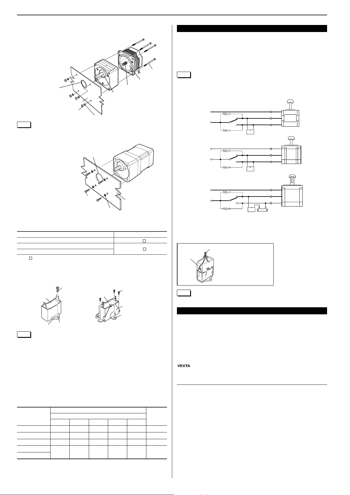
Operation
Be sure to connect the supplied capacitor and external resistor (for the SMK5 type only), as
shown in the figures.
Flip the switch to CW to rotate the motor in the clockwise direction and to CCW for rotate the
motor in the counterclockwise direction. When the power is turned off, the motor stops within
±
3.6˚. (The direction of rotation indicates the rotational direction of the motor shaft when viewed
from the motor shaft side.)
Connection
◆
Do not give any constraint to the motor shaft.
If the motor shaft is constrained with a load torque exceeding the motor torque, the motor cannot be started and a vibrating condition will occur, resulting in a significant decrease in motor
life. Be sure to use a load torque that is less than the motor torque.
◆
Use a gearhead that is below the permissible torque.
The load torque of the gearhead must be below the permissible gearhead torque. If a load
torque exceeding the permissible gearhead torque is used, it may damage the gearhead.
Precautions for use
●
SMK0 type
●
SMK2 type
●
SMK5 type
This Operating Manual may be revised without prior notice due to product improvement,
changes in specifications or other revisions.
is a registered trademark of ORIENTAL MOTOR CO., LTD., in Japan and other coun-
tries.
© Copyright ORIENTAL MOTOR CO., LTD. 2002
SW
CW
CCW
CCW CW
Red
White
Blue
Capacitor
Motor
R0 C0
R0 C0
Single-Phase
24 V
or
Single-Phase
100/ 115 V
Single-Phase
100/ 115 V
SW
CW
CCW
CCW CW
Red
Gray
Blue
Capacitor
Motor
R0 C0
R0 C0
External resistance
Single-Phase
100/ 115 V
or
Single-Phase
200/ 230 V
SW
CW
CCW
CCW CW
Red
Gray
Blue
Capacitor
Motor
R0 C0
R0 C0
After connecting a lead wire to
the Capacitor terminal, cover
it with the Capacitor cap.
CHC3115AUL
E56078 TP-31
CHC3115AULCHC3115AUL
E56078 TP-31E56078 TP-31
Capacitor cap
Lead wire
[How to install the capacitor cap]
SMK014K-A, SMK014K-AA, SMK014K-B, SMK550C-GN and SMK550C-GNB are
not supplied.
To protect the switch and relay contacts, be sure to connect a surge suppresser circuit.
NOTE
Refer to the catalog for
DC excitation.
Hexagon socket screw
or
Cross recessed screw
Spot facing or through
hole for pilot
Spring washer
Mounting plate
∗
1
This table indicates the overhung load and thrust load of the gearhead.
∗
2
Set to the dead mass of the motor or less where denoted by an asterisk 2 (
∗
2
).
When the pinion shaft type motor is used, the direction of rotation of the gearhead (sold separately) output shaft is opposite to that of the motor when the gear ratio is
25, 30
and 36.
For the geared motor, the direction of rotation of the gear output shaft is opposite when the
gear ratio is
15, 18, 100
and
120
.
NOTE
 Loading...