

Page 1

HP-7420-4
Compact & Lightweight Stepping Motor and Driver Package
PMC Series
• Standard Type
• MG Geared Type
• Harmonic Geared Type
OPERATING MANUAL
Table of Contents
Safety precautions................................. Page 2
Product verification ................................ Page 5
Names and function of driver parts ....... Page 7
Installation.............................................. Page 9
Driver function swithces ........................ Page 15
Input/output signals ............................... Page 16
Connections........................................... Page 22
Motor current adjustment ...................... Page 24
Troubleshooting..................................... Page 27
Specifications......................................... Page 30
Installing and wiring in compliance........ Page 33
with EMC directive
Thank you for purchasing an Oriental Motor product.
This Operating Manual describes product handling procedures and safety precautions.
• Please read it thoroughly to ensure safe operation.
• Always keep the manual where it is readily available.
1
Page 2

Safety precautions
Only qualified personnel should work with the product.
Use the product correctly after thoroughly reading the section “Safety precautions.”
The precautions described below are intended to prevent danger or injury to the user and
other personnel through safe, correct use of the product. Use the product only after
carefully reading and fully understanding these instructions.
Warning
Handling the product without observing the instructions that accompany a “Warning”
symbol may result in serious injury or death.
Caution
Handling the product without observing the instructions that accompany a “Caution”
symbol may result in injury or property damage.
Note
The items under this heading contain important handling instructions that the user should
observe to ensure safe use of the product.
Warning
General
• Do not use the product in explosive or corrosive environments, in the presence of
flammable gases, locations subjected to splashing water, or near combustibles. Doing
so may result in fire or injury.
• Assign qualified personnel the task of installing, wiring, operating/controlling, inspecting
and troubleshooting the product. Failure to do so may result in fire or injury.
Installation
• Install the motor and driver in their enclosures in order to prevent injury.
Connection
• Keep the driver’s input-power voltage within the specified range to avoid fire.
• The driver power supply to be used should be a DC power supply where the primary
and secondary sides are provided with reinforced insulation. Otherwise, an electric
shock may occur.
• Connect the cables securely according to the wiring diagram in order to prevent fire.
• Do not forcibly bend, pull or pinch the cable. Doing so may fire.
2
Page 3

Operation
• Turn off the driver power in the event of a power failure, or the motor may suddenly start
when the power is restored and may cause injury or damage to equipment.
• When you want to use the motor in a vertical application, take position holding
measures. When the power is turned off, the motor will lose the holding brake force.
The movable part will drop and possibly cause injury to personal and damage to the
equipment.
• Do not turn the output current off input to “ON” while the motor is operating. The motor
will stop and lose its holding ability, which may result in injury or damage to equipment.
Repair, disassembly and modification
• Do not disassemble or modify the motor or driver. This may cause injury. Refer all such
internal inspections and repairs to the branch or sales office from which you purchased
the product.
Caution
General
• Do not use the motor and driver beyond their specifications, or injury or damage to
equipment may result.
• Do not touch the motor or driver during operation or immediately after stopping. The
surfaces are hot and may cause a burn.
Transportation
• Do not hold the motor output shaft or motor cable. This may cause injury.
Installation
• Keep the area around the motor and driver free of combustible materials in order to
prevent fire or a burn.
• To prevent the risk of damage to equipment, leave nothing around the motor and driver
that would obstruct ventilation.
• The motor and driver should be firmly secured on the metallic plate in order to prevent
personal injury or equipment damage.
• Provide a cover over the rotating parts (output shaft) of the motor to prevent injury.
3
Page 4
Operation
• Use a motor and driver only in the specified combination. An incorrect combination may
cause a fire.
• To avoid injury, remain alert during operation so that the motor can be stopped
immediately in an emergency.
• Before supplying power to the driver, turn all control inputs to the driver to “OFF.”
Otherwise, the motor may start suddenly and cause injury or damage to equipment.
• Make sure that the output power off input of the driver is turned on if you want to move
the motor shaft directly (e.g. for manual positioning). This caution is to prevent
personal injury.
• When an abnormality is noted, stop the operation immediately, or fire or injury may
occur.
Disposal
• When disposing of the motor or driver, treat them as ordinary industrial waste.
Note
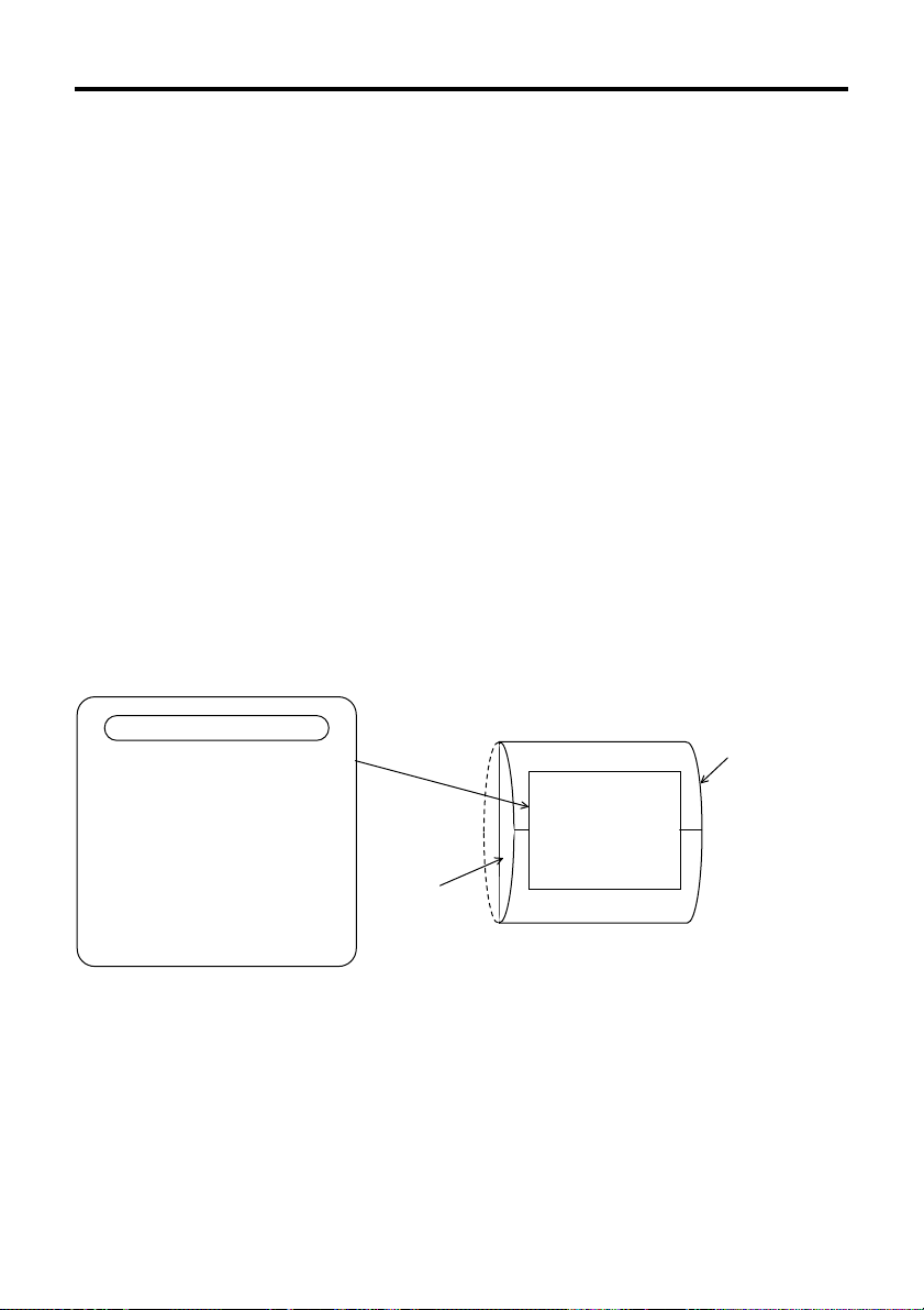
Before using the product, read the content of the label carefully.
The content and stick position of the label are as follows.
ATTENTION
Please pay attention to the following
to the product work in the best
condition.
●Do not take the product out of the
protective bag until ready to use it.
●Do not touch parts and contacts to
avoid electrostatic damage.
●Do not expose the product to
vibration or shock.
●Keep the product away from dusty
and humid condition.
4
Protective bag
Driver
MNX7227
Page 5

Product verification
Equipment checklist
• Motor........................................................................ 1
• Driver ....................................................................... 1
• M2.5 Cross recessed head machine screws
with washer for mounting the motor
(for only MG geared type)........................................ 4
• Connector for signals
6-173977-4 (AMP), 6-173977-8 (AMP).................... 2
• Connector for power supply
6-173977-3 (AMP) ................................................... 1
• Connector for motor connection
6-173977-5 (AMP) ................................................... 1
• Operating manual .................................................... 1
Note
Do not take the product out of the protective bag until ready to use it. Otherwise, the driver
may be damage.
Model numbers and motor/driver combinations
The PMC series is a combined package which includes a stepping motor and driver.
This operating manual is designated for the following products.
Package model number
PMC33A3
PMC33B3
PMC35A3
PMC35B3
PMC33A1-MG∗
PMC33B1-MG∗
PMC33A1-HG∗
PMC33B1-HG∗
1
1
2
2
Motor model number
PMM33A2
PMM33B2
PMM35A2
PMM35B2
PMM33A-MG∗
PMM33B-MG∗
PMM33A-HG∗
PMM33B-HG∗
1
1
2
2
Driver model number
PMD03CA
The box (∗1) represents the desired gear ratio (3.6, 7.2, 10, 20, 30, 50).
The box (∗
2
) represents the desired gear ratio (50, 100).
Note
The motor and the driver are precision equipment and should not be dropped or subject to
any physical shocks.
5
Page 6

Interpreting the model number
P M C 3 3 A 3P M C 3 3 A 3
P M C 3 3 A 3
P M C 3 3 A 3P M C 3 3 A 3
Reference number
Shaft type
A:Single shaft
B:Double shaft
Motor case length
3:31mm (1.22in.)
5:50.5mm (1.99in.)
Motor frame size
3:28mm (1.1in.) sq.
Compact & lightweight stepping motor and driver package
PMC series
P M C 3 3 A 1 - M G 3.6P M C 3 3 A 1 - M G 3.6
P M C 3 3 A 1 - M G 3.6
P M C 3 3 A 1 - M G 3.6P M C 3 3 A 1 - M G 3.6
Geared type
MG : MG gear
HG : Harmonic gear
Gear ratio
MG geared type
3.6: 3.6:1 20 : 20:1
7.2: 7.2:1 30 : 30:1
10 : 10:1 50 : 50:1
Harmonic geared type
50 : 50:1 100 : 100:1
Reference number
Shaft type
A:Single shaft
B:Double shaft
Motor case length
Motor frame size
3:28mm (1.1in.) sq.
Compact & lightweight stepping motor and driver package
PMC series
6
Page 7
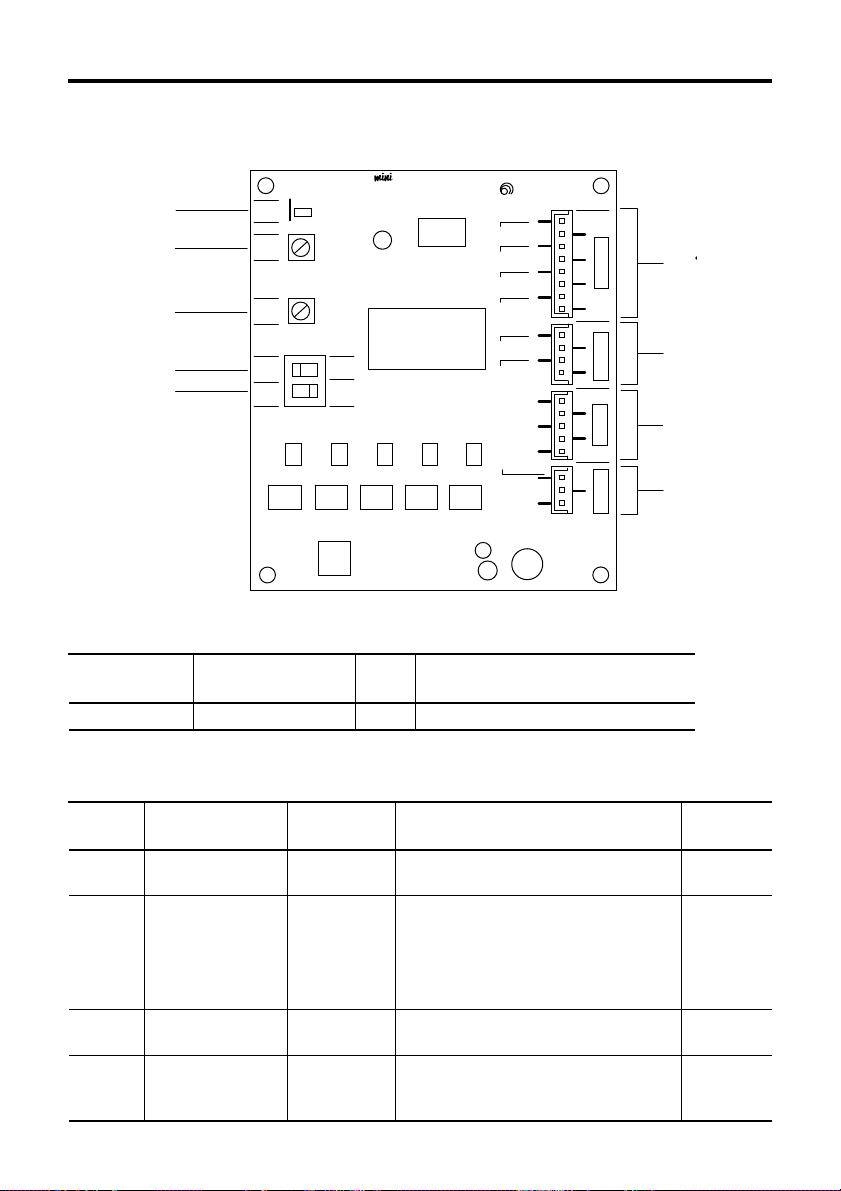
Names and functions of driver parts
Illustration shows the view from the connector side.
STEPPING DRIVER
CW/P.
CCW/D.
C.OFF
F/H
C.UP
TIM
BLU
RED
ORG
GRN
BLK
24 / 36V
GND
NC
1
+
+
CN1CN4CN3
+
+
+
+
+
1
1
1
CN2
SIGNAL 1
SIGNAL 2
MOTOR
POWER
①
②
③
④
⑤
LED indications
POWER
RUN
STOP
F
2P
VEXTA
H
1P
⑥
⑦
⑧
⑨
Indication
LED name
Color
① POWER Power input LED Green
Potentiometers and switches
Indication
② RUN
③STOP
④ F/H
⑤ 2P/1P
Name
Run potentiometer
Stop potentiometer
Step angle switch
Pulse input mode
switch
Factory
setting
0.35A/phase
0.175A/phase
F
1P
Current adjustment potentiometer used
when motor is running.
Motor standstill current adjustment
potentiometer used when current has
been cut back by the automatic current
cutback function when there is no pulse
input (motor standstill).
The motor step angle can be set to full
step or half step with this switch.
The pulse signal input mode can be set
to 1-pulse input mode or 2-pulse input
mode this switch.
Conditions when LED ON
Lights when the power is input.
Function
Page
reference
Page25
Page25, 26
Page15
Page15
7
Page 8
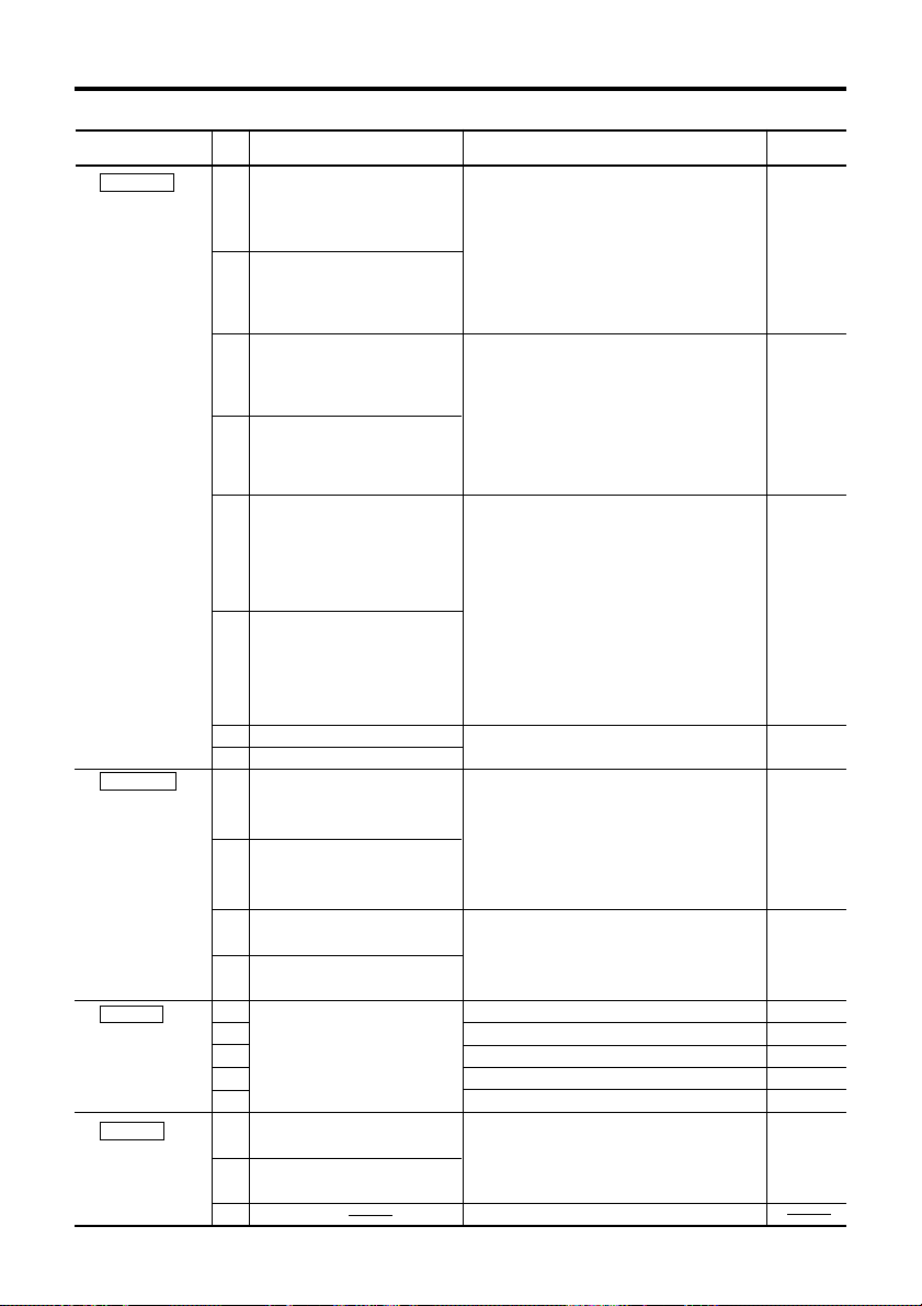
Terminals
Indication Terminal name Function
⑥ SIGNAL 1
6-173977-8
(AMP)
∗1
The selection of
the pulse signal
input mode can
be set with the
pulse input
mode switch.
∗2
In this table, the
rotation direction
shows that of
motor output
shaft.
For harmonic
geared type and
gear ratio 10:1 of
MG geared type,
the motor rotation
direction is
opposite to the
output shaft
rotation direction.
⑦ SIGNAL 2
6-173977-4
(AMP)
⑧ MOTOR
6-173977-5
(AMP)
⑨ POWER
6-173977-3
(AMP)
8
Pin
No.
(Pulse/CW Pulse
CW/P.+
1
2
CW/P.
CCW/D.+
3
CCW/D.
4
C.OFF+
5
C.OFF
6
F/H+
7
F/H
8
C.UP+
1
2
C.UP
TIM+
3
TIM
4
1
2
Motor Connection Terminal
3
4
5
24/36V
1
GND
2
3
NC
Signal Input
Terminal)
(Pulse/CW Pulse
Signal Input
Terminal)
(Rotation Direction/
CCW Pulse Signal
Input Terminal)
(Rotation Direction/
CCW Pulse Signal
Input Terminal)
(All Windings Off
Signal Input
Terminal)
(All Windings Off
Signal Input
Terminal)
(Step Angle Signal Input Terminal)
-
(Step Angle Signal Input Terminal)
(Automatic Current
Cutback Release
Signal Input Terminal)
(Automatic Current
-
Cutback Release
Signal Input Terminal)
(Excitation Timing
Signal Output Terminal)
(Excitation Timing
Signal Output Terminal)
(Power Supply
Connection Terminal)
(Power Supply
Connection Terminal)
The pulse mode signal is input to this
terminal. The direction of the motor’s
rotation is determined by the following
rotation direction input terminal.
(When in 2-pulse input mode the CW
direction command pulse signal is input
to this terminal.)
The rotation direction signal is input to
this terminal. When a signal is input to
the terminal the motor output shaft will
rotate the counterclockwise direction.
(When in 2-pulse input mode the CCW
direction command pulse signal is input
to this terminal.)
The all windings off signal is input to this
terminal.
When a signal is input to the terminal the
driver will cut the power supply to the
motor.
The motor torque will then be reduced to
zero and the motor shaft can be rotated
freely for adjustment.
This function is used when manual
positioning etc. is required.
The motor step angle is input to this
terminal.
The automatic current cutback release
signal is input to this terminal.
Signal for deactivating the automatic
current cutback function, which cuts back
the output current to the motor when it is
standstill.
Signal indicating that the motor excitation
sequence is at step “0”.
Connect this terminal to the blue lead wire.
Connect this terminal to the red lead wire.
Connect this terminal to the orange lead wire.
Connect this terminal to the green lead wire.
Connect this terminal to the black lead wire.
Connect this terminal to a “+” side of
DC24V or DC36V and GND.
No connection.
Page
reference
Page16, 17
Page16, 17
Page18, 19
Page19
Page20
Page21
Page22, 23
Page22, 23
Page22, 23
Page22, 23
Page22, 23
Page22
Page 9
Installation
Motor installation
Motor installation location
To prevent motor damage, install in a location with the following conditions.
• Indoors (The motor is designed and manufactured to be used as an internal component
within other equipment.)
• Ambient temperature range
For harmonic geared type: 0°C~+40°C (+32°F~+104°F) (non-freezing)
• Ambient humidity below 85% (non-condensing)
• No explosive, combustible, or corrosive gases
• No direct sunlight
• No dust or conductive particles (i.e. metal chips or shavings, pins, or wire fragments
etc.)
• No water, oil, or other fluids
• Where the motor is able to dissipate heat easily
• No continuous vibration or sudden shocks
• No nearby radiation, magnetic field, or air vacuum environment
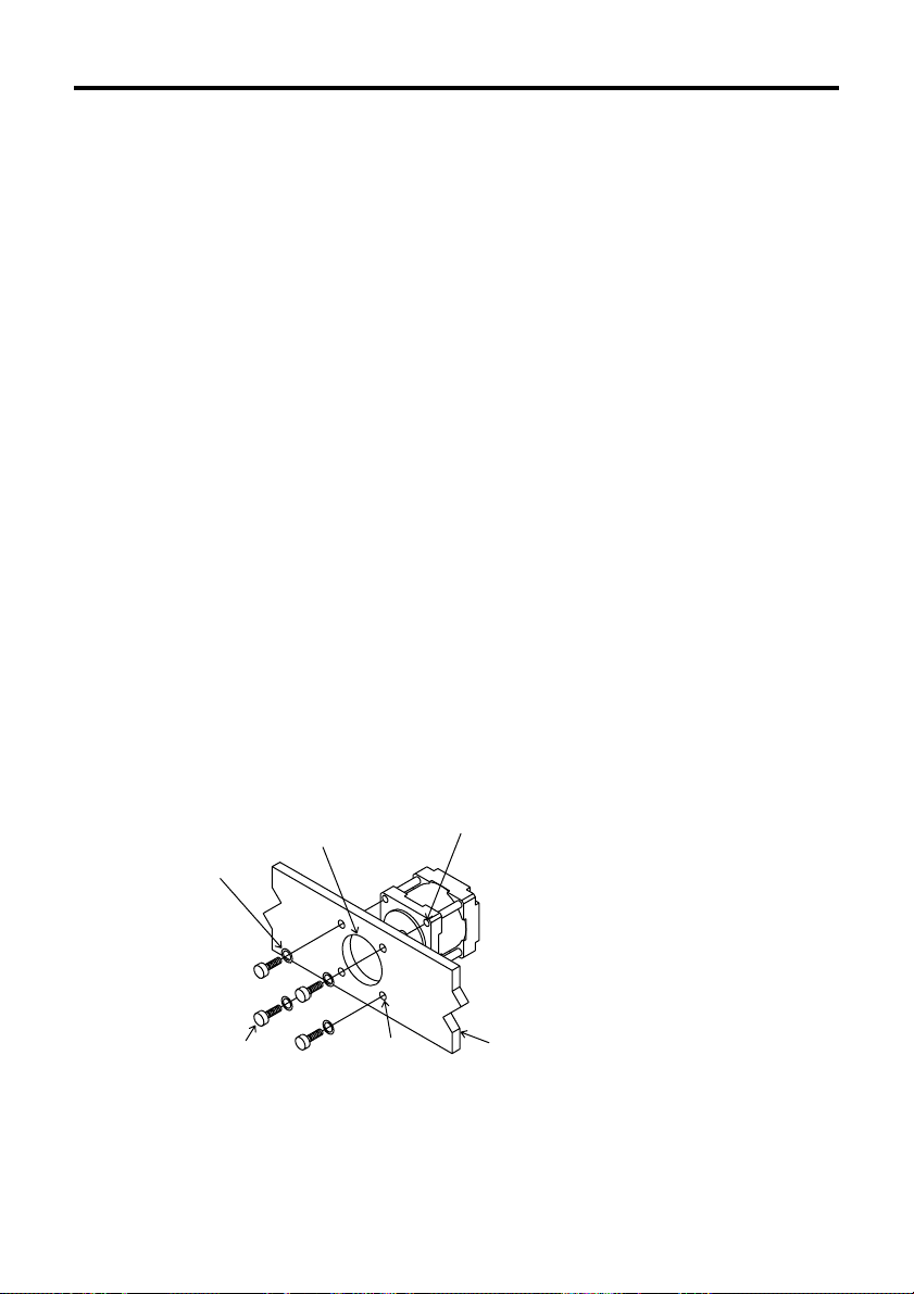
How to install the motor
To allow for heat dissipation and to prevent vibration, be sure to securely attach the motor
to solid metal surface.
The motor flange incorporates a pilot diameter. Use this pilot diameter as a guide for
alignment when mounting the motor.
-
10°C~+50°C (+14°F~+122°F) (non-freezing)
PMC3A(B)3
M2.5
Spring washer
M2.5
Recessed cross
head screws
Spot facing or
through hole for pilot
Ø3(.12)-4holes
4-M2.5 P0.45
Mounting plate
9
Page 10
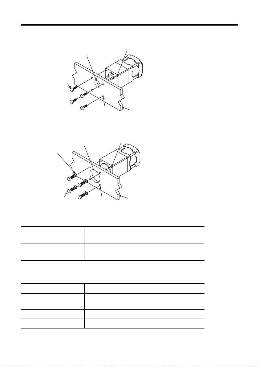
PMC33A(B)1-MG
M2.5
Cross recessed
head machine
screws with
washer (attached)
Spot facing or
through hole for pilot
4-M2.5 P0.45
Ø3(.12)-4holes
Mounting plate
PMC33A(B)1-HG
M3
Spring washer
M3
Hexagonal
socket screws
Spot facing or
through hole for pilot
Ø3.5(.14)-4holes
4-M3 P0.5
Mounting plate
The following hardware (not supplied) is needed to mount the motor.
For the installation of the MG geared type, use the supplied screws.
PMC3A(B)3
PMC33A(B)1-HG
・M2.5 Recessed cross head screws : 4
・M2.5 Spring washers : 4
・M3 Hexagonal socket screws : 4
・M3 Spring washers : 4
Select screws with a length appropriate for the thickness of the mounting plate.
(Refer to the below table.)
Model
PMC33A(B)3
PMC35A(B)3
PMC33A(B)1-MG
PMC33A(B)1-HG
Length of the screws [Unit: mm (inch)]
thickness of the mounting plate +2.5 (0.1)
thickness of the mounting plate +3.5 (0.14)
thickness of the mounting plate +5 (0.2)
10
Page 11
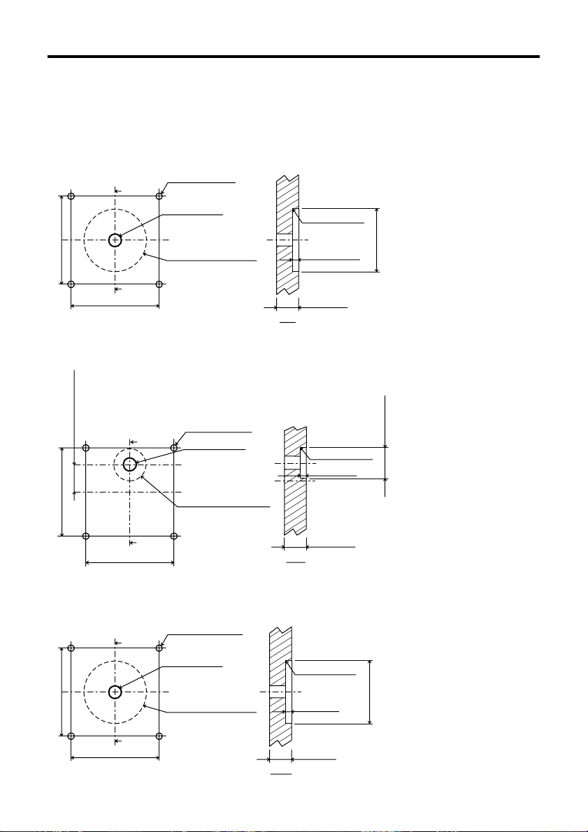
Motor mounting plate dimensions
[unit: mm (inch)]
PMC3A(B)3
Ø3(.12)-4holes
Ø5.5(.22)min.
Shaft hole
+0.033
+.0013
()
0
.87
0
Ø22
Spot facing or
through hole for pilot
23±0.2(.9±.008)
23±0.2(.9±.008)
X
X’
PMC33A(B)1-MG
Ø3(.12)-4holes
6±0.2(.2±.008)
X
Ø5.5(.22)min.
Shaft hole
R0.3(.01)max.
1.5(.059)min.
2(.08)min.
X-X’
R0.5(.02)max.
2(.08)min.
0
+.0013
.87
()
+0.033
0
Ø22
Ø11.5(.45)
23±0.2(.9±.008)
X’
23±0.2(.9±.008)
PMC33A(B)1-HG
X
23±0.2(.9±.008)
23±0.2(.9±.008)
X’
Ø11.5(.45)
Spot facing or
through hole for pilot
Ø3.5(.14)-4holes
Ø8.5(.33)min.
Shaft hole
+0.033
+.0013
()
0
.87
0
Ø22
Spot facing or
through hole for pilot
X-X’
R0.3(.01)max.
2(.08)min.
5(.2)min.
X-X’
2(.08)min.
0
+.0013
.87
()
+0.033
0
Ø22
11
Page 12

Connecting the motor to the drive mechanism (Load)
Ball screw
Stepping motor
Coupling
Proper alignment is necessary when
connecting the drive mechanism (load) to
the motor shaft. Use a flexible coupling.
Note
• Inadequate alignment may reduce the life span of the motor bearings or damage the
motor shaft.
• Exceeding the permissible overhung load or permissible thrust load will damage or shorten
the life span of the bearings and motor shaft.
Do not exceed the permissible overhung load and thrust load as indicated in the
following chart.
• For geared motor, do not separate the motor and the gearhead.
Permissible overhung load [Unit: N (lb.)]
Distance from the end
of the shaft [mm (inch)]
PMC3
A(B)3
1
PMC33A(B)1-MG
PMC33A(B)1-HG
∗
∗
2
0
25 (5.51)
9.2 (2.02)
140 (30.8)
Permissible thrust load [Unit: N (lb.)]
PMC33A(B)3
PMC35A(B)3
PMC33A(B)1-MG
PMC33A(B)1-HG
1
The box (∗
The box (∗
) represents the desired gear ratio (3.6, 7.2, 10, 20, 30, 50).
2
) represents the desired gear ratio (50, 100).
1
∗
2
∗
1 (0.22)
1.7 (0.374)
10 (2.2)
100 (22)
5 (0.2)
34 (7.49)
11.4 (2.51)
160 (35.2)
10 (0.39)
52 (11.4)
15 (3.3)
200 (44.1)
15 (0.59)
21.9 (4.82)
240 (52.8)
12
Page 13

Driver installation
Driver installation location
To prevent driver damage, install in a location with the following conditions.
• Indoors (The driver is designed and manufactured to be used as an internal component
within other equipment.)
Ambient temperature range 0°C~+40°C (+32°F~+104°F) (non-freezing).
Install a forced-air cooling fan if ambient temperatures exceed +40°C (+104°F).
• Ambient humidity below 85%(non-condensing)
• No explosive, combustible, on corrosive gases
• No direct sunlight
• No dust or conductive particles (i.e. metal chips or shavings, pins, or wire fragments
etc.)
• No water, oil, or other fluids
• Where the driver is able to dissipate heat easily
• No continuous vibration or sudden shocks
• No nearby radiation, magnetic field, or air vacuum environment
• If the driver is installed in a switch box or other enclosed area, and near a heat source,
be sure to establish ventilation holes. The heat generated by the driver will cause the
ambient temperature to rise which could consequently damage the driver.
• If the driver is installed near a source of vibration, and this vibration is transmitted to the
driver, attach a shock absorber to prevent driver damage.
• If the driver is installed near a source of noise interference (i.e. high frequency welding
machine, electromagnetic switch, etc.) install a noise filter, or connect it to a separate
power source to reduce the effect of the interference, otherwise the motor may not
operate correctly.
• Leave a space of at least 25mm (1in.). If using more than one driver, leave a space of at
least 20mm (0.8in.) between each driver. Driver heat generation will cause the ambient
temperature to rise, and if the permissible ambient operating temperature is exceeded,
driver damage may result.
How to install the driver
The driver is designed to cool naturally by convection.
Secure the driver to a metal plate made of steel, aluminium or other material having good
thermal conductivity.
The following hardware (not supplied) is needed to mount the driver.
• M3 Screws :4
• M3 Spring washers :4
• Insulation type spacers : 4
• M3 Nuts :4
13
Page 14

Driver mounting plate dimensions
Horizontal mounting Vertical mounting
Connector
Securing the driver
1. Insert spring washers and M3 screws from the surface of the connector side of the
circuit board.
2. Insert the spacer between the driver and the mounting plate, and secure by using M3
nuts.
• Spacer size: Ø9mm (0.35in.) max. 6mm (0.24in.) min. long
• Screw tightening torque: 0.5N·m (71oz-in)
[Unit: mm (inch)]
14
56(2.2)
50±0.3(1.97±.01)
3(.12)
72(2.83)
66±0.3(2.6±.01)
3(.12)
M3 Spring washer
Ø3.2(.13)-4holes
M3 Screw
Insulation
type spacer
M3 nut
Driver
6(.24)min.
Chassis
Page 15

Driver function switches
The driver has various operation functions which are set with the function switches.
ON
ON
12
H
1P
Step angle switch
Pulse input mode switch
OFF
F
2P
∗The white square section of the function switch represents the switch lever.
Step angle switch (Factory setting : F)
When the switch is set to:
ON
1
F
2
H
“F” (Full step)
Standard type: 1step = 0.72° (1 rotation = 500 pulses)
Geared type: 1step= 0.72°×
1
gear ratio
(1 rotation = 500×gear ratio pulses)
“H” (Half step)
Standard type: 1step = 0.36° (1 rotation = 1000 pulses)
Geared type: 1step = 0.36°×
1
gear ratio
(1 rotation =1000×gear ratio pulses)
Pulse input mode switch (Factory setting : 1P)
Select the appropriate pulse input mode to correspond to
your controller with this switch.
When the switch is set to the 1P position, 1-pulse input
mode is established and motor rotation is controlled by
pulse signals and rotation direction signals.
When the pulse input mode switch is set to the 2P position,
2-pulse input mode is established and motor rotation is
controlled by CW and CCW pulse signals.
2P
ON
12
1P
15
Page 16

Input/output signals
Input signals
The input signals to the driver and their functions are specified below.
Pulse/CW pulse signals
Rotation direction/CCW pulse signals
The diagram below shows the input circuits and an example connection to a controller.
Driver input
Controller output
Open collector
output
PLS(CW)
DIR.(CCW)
0
V
R
R
(Internal circuit)
Pulse(CW)
+
1
220Ω
CW/P.
2
‑
Rotation direction(CCW)
+
3
220Ω
CCW/D.
4
‑
20mA max.
20mA max.
1-Pulse input mode
Pulse signal
When the photocoupler state changes from “ON” to “OFF”, the motor rotates one step.
The direction of rotation is determined by the following rotation direction signals.
Rotation direction signal
The rotation direction signal is input to rotation direction/CCW pulse signal input terminal.
An input signal at “photocoupler ON” commands a clockwise direction rotation.
(For harmonic geared type and gear ratio 10:1 of MG geared type: counterclockwise)
An input signal at “photocoupler OFF” commands a counterclockwise direction rotation.
(For harmonic geared type and gear ratio 10:1 of MG geared type: clockwise)
The number within refers to the pin
number of driver connector SIGNAL 1.
The information in the brackets ( ) refers to
signals when in 2-pulse input mode.
Keep the voltage between DC5V and DC24V.
When voltage is equal to DC5V, external
resistance R is not necessary.
When voltage is above DC5V, connect
external resistance R and keep the input
current below 20mA.
2-Pulse input mode
CW∗ pulse signal
When the photocoupler state changes from “ON” to “OFF”, the motor rotates one step in
the clockwise direction.
(For harmonic geared type and gear ratio 10:1 of MG geared type: counterclockwise)
CCW∗ pulse signal
When the photocoupler state changes from “ON” to “OFF”, the motor rotates one step in
the counterclockwise direction.
(For harmonic geared type and gear ratio 10:1 of MG geared type: clockwise)
∗ CW and CCW refer to clockwise and counterclockwise directions respectively, from a
reference point of facing the motor output shaft.
16
Page 17

Relation to the pulse input mode switch
When the switch is set to the 1P position, motor rotation is controlled by pulse signals and
rotation direction signals.
When the switch is set to the 2P position, motor rotation is controlled by CW pulse signals
and CCW pulse signals.
Pulse waveform characteristics
1-Pulse input mode
5µs
min.
2µs
max.
5µs
min.
2µs
max.
Photocoupler ON
Photocoupler OFF
Photocoupler ON
Photocoupler OFF
90%
10%
10
µsmin.
10
Pulse signal
µsmin.
Rotation direction signal
2-Pulse input mode
Photocoupler ON
Photocoupler OFF
Photocoupler ON
Photocoupler OFF
• The shaded area indicates when the photocoupler diode is ON. The motor moves when
the photocoupler states changes from ON to OFF as indicated by the arrow.
• The pulse voltage is 4~5V in the “photocoupler ON” state, and 0~0.5V in the
“photocoupler OFF” state.
• Input pulse signals should have a pulse width over 5µs, pulse rise/fall below 2µs, and
a pulse duty below 50%.
• Keep the pulse signal in the “photocoupler OFF” state when no pulse is being input.
• The minimum interval time when changing rotation directions is 10µs.
• In 1-pulse input mode, leave the pulse signal at rest “photocoupler OFF” when
changing rotation directions.
• In 2-pulse input mode, do not input CW and CCW pulse signals at the same time.
Inputting a pulse signal while the other pulse signal is already in the “photocoupler
ON” state will result in erratic motor rotation.
90%
10%
2µs
max.
5µs
min.
5µs
min.
2µs
max.
10
CW pulse signal
CCW pulse signal
µsmin.
17
Page 18

All windings off signal
The diagram below shows the input circuit and an example connection to a controller.
The number within refers to the pin
number of driver connector SIGNAL 1.
Keep the voltage between DC5V and DC24V.
When voltage is equal to DC5V, external
resistance R is not necessary.
When voltage is above DC5V, connect
external resistance R, and keep the input
current below 20mA.
Controller output
Open collector
output
C.OFF
Driver input
+
C.OFF
‑
(Internal circuit)
220Ω
5
6
20mA max.
0
V
R
When the all windings off signal is in the “photocoupler ON” state, the current to the motor
is cut off and motor torque is reduced to zero. The motor output shaft can then be rotated
freely by hand.
When the all windings off signal is in the “photocoupler OFF” state, the motor holding
torque is proportional to the current set by the current adjustment rotary switches. During
motor operation be sure to keep the signal in the “photocoupler OFF” state.
This signal is used when moving the motor by external force or manual home positioning
etc. is desired. If this function is not needed, it is not necessary to connect this terminal.
Switching the all windings off signal from “photocoupler ON” to “photocoupler OFF” does
not alter the excitation sequence.
When the motor shaft is manually adjusted with the all windings off signal input, the shaft
will shift up to ±3.6°
(geared type: ±3.6°/gear ratio) from the position set after the all windings off signal is
released.
18
Page 19

Manual detection of the home position
Input the all windings off signal, set the motor to the desired position, then release the all
windings off signal.
All windings off signal input
All windings off
signal release
All windings off
signal input
Photocoupler ON
Photocoupler OFF
Home position
set
OFF OFF
ON
Note
For geared type, do not do manual detection of the home position. It may cause damage
the gearhead and may cause the following problems.
• The motor makes a strange noise.
• The motor does not rotates correctly.
Step angle signal
The diagram below shows the input circuit and an example connection to a controller.
Driver input
+
F / H
‑
(Internal circuit)
220Ω
7
8
20mA max.
Controller output
Open collector
output
F / H
0
V
R
Half Step
Standard type:
When the step angle signal is in the
“photocoupler ON” state, it is set to half-step
mode (0.36°/step, 1 rotation 1000 pulses)
Geared type:
When the step angle signal is in the
“photocoupler ON” state, it is set to half-step
mode
(0.36°× / step,
1
gear ratio
1 rotation 1000×gear ratio pulses)
The number within refers to the pin
number of driver connector SIGNAL 1.
Keep the voltage between DC5V and DC24V.
When voltage is equal to DC5V, external
resistance R is not necessary.
When voltage is above DC5V, connect
external resistance R, and keep the input
current below 20mA.
Full Step
Standard type:
When the step angle signal is in the
“photocoupler OFF” state, it is set to fullstep mode (0.72°/step, 1 rotation 500
pulses)
Geared type:
When the step angle signal is in the
“photocoupler OFF” state, it is set to fullstep mode
(0.72°× / step,
1
gear ratio
1 rotation 500×gear ratio pulses)
Note
When the step angle signal is used, the switch must be set to the F position.
19
Page 20

Automatic current cutback release signal
The diagram below shows the input circuit and an example connection to a controller.
Controller output
Open collector
output
C.UP
Driver input
+
C.UP
‑
(Internal circuit)
220Ω
1
2
20mA max.
0
V
R
The number within refers to the pin
number of driver connector SIGNAL 2.
Keep the voltage between DC5V and DC24V.
When voltage is equal to DC5V, external
resistance R is not necessary.
When voltage is above DC5V, connect
external resistance R, and keep the input
current below 20mA.
• When the automatic current cutback release signal is in the “photocoupler OFF” state,
the automatic current cutback function is activated; 0.1s. after the pulse is stopped the
motor output current is automatically cut back, reducing motor and driver heat.
(The factory setting for the current cutback is 50%. In order to change this, refer to the
instructions for adjusting the current at motor standstill on pages 25, 26)
• When the maximum holding torque is needed, input “photocoupler ON” signal. The
automatic current cutback function is deactivated.
• When the automatic current cutback release signal is in the “photocoupler ON” state,
the automatic current cutback function is deactivated.
• Because the motor’s holding power is proportional to the motor output current, the motor’s
holding power is reduced when the current is cut back. (The motor has holding power
proportional to the current at motor standstill, which is set with the STOP potentiometer.
Refer to page 24.)
Note
Generally, automatic current cutback release signal should be set to “photocoupler OFF”
to suppress heat generation in the motor and driver.
20
Page 21

Output signals
The output signals from the driver and their functions are specified below.
Excitation timing signal
The diagram below shows the output circuit and an example connection to a controller.
Controller output
Driver input
(Internal circuit)
V
0
R
TIM
+
‑
3
4
10mA max.
The number within refers to the pin
number of driver connector SIGNAL 2.
Keep the voltage between DC5V and DC24V.
Keep the current below 10mA.
If the current exceeds 10mA, connect external
resistance R.
The excitation timing signal is output to indicate when the motor excitation (current flowing
through the winding) is in the initial stage (step “0” at power up ).
The excitation timing signal can be used to increase the accuracy of home position
detection by setting mechanical home position of your equipment (photo-sensor etc.) to
coincide with the excitation sequence initial stage (step “0”).
When connected as shown in the example connection, the signal will be “photocoupler
ON” at step “0”.
The excitation timing signal is output simultaneously with a pulse input each time the
excitation sequence returns to step “0”.
The excitation sequence will complete one cycle for every 7.2° rotation of the motor output
shaft.
When the power is turned ON, the excitation sequence is reset to step “0”.
Relation to the step angle switch
When the switch is set to the F position:
Full step: signal is output once every 10 pulses
(Standard type: 0.72°/step, Geared type: 0.72°× / step)
When the switch is set to the H position:
Half step: signal is output once every 20 pulses
(Standard type: 0.36°/step, Geared type: 0.36°× / step)
1
gear ratio
1
gear ratio
Timing chart when in full step mode
123456789101112
Pulse
Rotation direction
Excitation timing
output
Step
0
123456789012
12
1
0
21
Page 22

Connections
Connecting the motor, driver and power supply
• For signal lines, use twisted pair wire of AWG28 (0.08mm2) or greater, and 1m (39.4in.)
or less in length.
• For power lines and when extending the motor lead wires use wires of AWG26 (0.14mm
or greater.
• Separate the signal lines from the power lines and motor lead wires by at least 30cm
(11.8in.). Do not band place the signal lines in the same duct as, or bind them together
with, power lines, as this makes it easier for noise to enter the signal line, which can
cause operating errors.
• Use an open collector transistor (sink type) for the controller signal output.
• If electrical noise generated by the motor lead wires or other equipment causes
operational errors, shield the signal lines with conductive tape or wire mesh etc. (not
supplied).
2
)
Pressure welding of the connectors
• The suitable wire size of AWG28 (0.08mm
having an outside diameter of 0.85mm (0.03in.)~1.05mm (0.04in.).
Use a wire rated at AWG26 (0.14mm
• Use the tool specified by the connector manufacturer (AMP 911790-1) for pressure
welding of the terminals.
Note
When pulling and inserting the connector to the driver, hold the connector itself.
Otherwise, the motor and the driver may be damaged.
2
) to AWG26 (0.14mm2) with a sheathing
2
) for the power line.
Driver power supply
The input power voltage should come from a DC24V or DC36V power supply which is
reinforced insulation.
The input current of the power supply is 0.7A or less.
Use a power supply which will supply sufficient input current.
(The current value for input power is a maximum value when connecting the drive
mechanism (load) to the motor shaft.)
Note
If the current from the power supply is insufficient the motor torque will be reduced and the
transformer may be damaged. The following abnormalities may also occur.
• Erratic motor rotation during high speeds
• Delayed motor start-up and stopping
22
Page 23

Example connections
Connection to user’s controller
Driver( )
①
+
CW / P.
+
CCW / D.
+
C.OFF
+
F / H
+
C.UP
+
TIM
BLU
RED
ORG
GRN
BLK
24 / 36V
+
GND
NC
②
③
④
⑤
SIGNAL1SIGNAL2MOTORPOWER
⑥
⑦
⑧
①
②
③
④
①
②
③
④
⑤
①
②
③
Pulse/CW pulse signal input
Rotation direction/
CCW pulse signal input
All windings off signal input
Step angle signal input
Automatic current cutback
release signal input
Excitation timing
Signal output
Blue
Red
Orange
Green
Black
+24 / 36V
GND
N.C (power supply which is reinforced insulation)
Stepping motor
+
DC24V or DC36V
Power supply
-
User’s controller
V0(+5V〜24V)
R
1
R
1
R
1
R
1
R
1
R
2
R
0
GND
Note: For operations involving sudden
deceleration or the driving of large
inertial loads, connect a capacitor
of 1000µF or more to suppress
the motor’s regenerative voltage.
+24V±10%
GND
DC POWER
+
SUPPLY
‑
Input signal connections
Keep the voltage between DC5V and DC24V.
When voltage is equal to DC5V, external resistance R
When voltage is above DC5V, connect external resistance R
is not necessary.
1
and keep the input
1
current below 20mA.
Output signal connections
Keep the voltage between DC5V and DC24V.
Keep the current below 10mA.
If the current exceeds 10mA, connect external resistance R2.
Turning on the power
Before turning the power ON, be sure that the signal lines, motor lead wires, power line,
and earth line are all properly connected.
The power LED lights when turning on the power (The power LED keeps lighting during
turning on the power.).
23
Page 24

Motor current adjustment
)
The PMC driver is shipped with the motor rated current set to 0.35A/phase (and the
standstill current reduction (current cutback) ratio set to approximately 50%).
It is not necessary to adjust the current under normal operating conditions. However,
readjust the current setting in the following cases.
To reduce motor vibration Æ Reduce the motor running current
To reduce temperature rise of the motor and driverÆReduce the motor running current and the motor
To increase the motor’s standstill holding torqueÆ Raise the motor’s standstill current
Holding torque can be calculated using the following formulas
(Holding torque is proportional to output current.)
Current cutback ratio (%)=
× 100
Running current setting
Maximum holding torque [N·m (oz-in)]×Current cutback ratio (%)
Holding torque [N·m (oz-in)]=
100
Relationship between the potentiometers and the current
The relationship between the potentiometers and the current is shown below.
Standstill current setting
Motor running current
(Representative values)
0.4
0.3
0.2
0.1
Output current A/phase
0
0
RUN potentiometer scale
2 3
Factory setting
(0.35A/phase
2
3
1
41
Motor standstill current
(Representative values)
100
Factory setting
75
(50%)
50
25
Down ratio %
0
01 23
STOP potentiometer scale
2
1
4
3
24
Page 25

Adjusting the current using an ammeter
When more precise current adjustment are necessary, make them by connecting an
ammeter between the driver and motor, as shown below.
RUN potentiometer
Used to adjust the
motor’s running current
STOP potentiometer
Used to adjust the
current cutback ratio
at motor standstill
Step angle switch
Set to F
Custom driver ( )
RUN
STOP
FH
2P
1P
C.UP
BLU
RED
ORG
GRN
BLK
24/36V
+
GND
NC
+
1
2
3
4
5
6
SIGNAL 1
7
8
1
2
3
4
SIGNAL 2
1
2
3
4
MOTOR
5
1
2
3
POWER
(This power supply is not
needed when setting only the
5V
standstill current.)
Automatic current cutback
release input
SW1
Set according to the
explanation below.
DC ammeter
Blue
Red
Orange
Green
Black
Stepping motor
DC24V or DC36V+
-
power supply
-
+
+24 / 36V
GND
NC
Note
With the connections shown here, the current flowing to the ammeter is twice that of
a single phase.
Therefore, the current setting (per single phase) is equivalent to half the value indicated
on the ammeter.
For example, when the ammeter indicates 0.5A, the setting is 0.25A/phase.
Setting the motor running current
1. Confirm that the step angle switch set to F.
ON
1
F
2
H
2. Turn on SW1 for the C.UP automatic current cutback release input. (Do not input any
other signals)
3. After connecting the motor and DC ammeter, turn the power on.
4. Set the current using the RUN potentiometer.
∗Set the value indicated on the ammeter to twice the desired current setting (per phase).
5. Turn the power off.
6. Turn off SW1 for the C.UP automatic current cutback release input.
25
Page 26

Setting the motor standstill current
1. Confirm that the step angle switch set to F.
ON
1
F
2
2. Check that nothing is connected or input to the C.UP terminal, and that the SW1 switch
is turned off when using the connection shown above.
3. After connecting the motor and DC ammeter, turn the power on.
4. Set using the STOP potentiometer.
∗Set the value indicated on the ammeter to twice the desired current setting (per phase).
5. Turn the power off.
H
26
Page 27

Troubleshooting
Consult the following chart if the motor is not functioning properly. If the motor is still not
functioning properly after confirming the checkpoints below, contact your nearest sales
office as listed at the back of this manual.
Problem
No excitation in the
motor.
(The motor has no
holding torque and the
shaft can be turned
freely by hand.)
The motor does not
rotate.
The motor does not
rotate when a pulse
signal is input.
Check points
1. Is the driver POWER
LED On?
(If On, condition is normal)
2. Is the all windings off signal
being input to the driver?
3. Are the driver and motor
correctly connected?
4. Are the current adjustment
potentiometers (RUN or
STOP) set too low?
Note: If the motor still has no torque after checking the above conditions, the
driver is probably defective.
After reconfirming that the current voltage and connections are correct,
contact your nearest sales office for service.
First check the 4 items above.
5. In 2-pulse input mode
(pulse input mode
switch in the 2P position) is
either the pulse/CW pulse
or rotation direction/CCW
pulse signal input terminal
already in the “photocoupler
ON” state?
6. In 1-pulse input mode
(pulse input mode
switch in the 1P position) is
the pulse signal connected
to the rotation direction/
CCW pulse signal input
terminal?
If the POWER LED is not On, check if the
power supply is properly connected.
When the all windings off signal is input the
motor will lose all excitation (no holding
torque). Return the all windings off signal to
“photocoupler OFF”.
Check the wiring configuration and continuity
of the connector pressure weld. If the lead
wires have been extended, check the
extension connection.
These potentiometers control the output
current to the motor (refer to pages 24, 25,
26). If they are set too low return them to the
factory set positions.
The motor will not rotate if a pulse signal is
input when the other pulse signal input
terminal is already in the “photocoupler ON”
state.
Be sure to keep the pulse signal in the
“photocoupler OFF” state.
Connect the pulse signal to the pulse/CW
pulse signal input terminal.
Measures
27
Page 28

Problem
The motor rotates in
the wrong direction.
Motor rotation is
erratic.
Motor start up is
unstable.
Check points
7. In 2-pulse input mode
(pulse input mode switch
in the 2P position) are the
CW and CCW pulse signal
lines connected
backwards?
8. In 1-pulse input mode
(pulse input mode switch
in the 1P position) leave
the rotation direction/CCW
pulse signal input terminal
unconnected and try
inputting a pulse signal to
the pulse/CW pulse signal
input terminal.
9. Is harmonic geared type or
gear ratio of 10:1 of MG
geared type used?
First check items 5, 6, 7 and 8.
10. While in 2-pulse input
mode (pulse input mode
switch in the 2P position)
are the both of pulse/CW
pulse and rotation
direction CCW pulse
signal input at the same
time?
11. Are the motor shaft and
load properly aligned? Is
the load too heavy for the
motor?
Measures
Connect the CW pulse signal line to the
pulse/CW pulse signal input terminal, and
connect the CCW pulse signal line to the
rotation direction/CCW pulse signal input
terminal.
If the motor rotates in a counterclockwise
direction the motor and driver are normal.
Recheck the rotation direction signal levels.
(“photocoupler ON” = clockwise,
“photocoupler OFF” = counterclockwise)
For harmonic geared type and 10:1 of MG
geared type, due to the gear’s construction,
the direction of rotation of the output shaft is
opposite to the direction of rotation of the
motor itself as commanded by pulse input
(Refer to page 16).
Connect the CW pulse signal line to the
rotation direction/CCW pulse signal input
terminal, and connect the CCW pulse signal
line to the pulse/CW pulse signal input
terminal.
The motor will run irregularly if two pulses are
input at the same time.
Make sure the motor shaft and load are
securely attached and properly aligned.
Recheck the operating conditions, and if
necessary lighten the load.
28
Page 29

Problem
The motor rotates too
far or not far enough.
The motor loses
synchronization during
acceleration or while
running.
Motor vibration is very
high.
Motor temperature is
very high.
[The temperature of
the motor case should
be less than 100°C
(212°F). For harmonic
geared type: less than
70°C (158°F). ]
The automatic current
cutback function does
not work.
Check points
12.Does the step angle
required by your
equipment match the step
angle of the stepping
motor?
13.Is the number of pulses set
to match the amount of
motor rotation?
14.Is the starting pulse
frequency too high?
15.Is the acceleration/
deceleration time too
short?
16.Is the motor being affected
by noise interference?
17.Is the output torque too
high?
18.Try changing the pulse
frequency.
19.Is the motor running time
too long?
20.Is the automatic current
cutback release function
input?
21.Try changing the pulse
rate.
22.Is the pulse/CW pulse or
rotation direction/CCW
pulse signal input
“photocoupler ON”
after the completion of the
pulse signal?
23.Is automatic current
cutback release
function being input?
Measures
Check the setting of the step angle switch
located on the driver.
Check the controller pulse setting.
Check this by decreasing the frequency.
Check this by increasing the acceleration/
deceleration time.
Check this by running the motor while the
machine suspected of producing the noise
interference is off.
Try reducing the motor running current with
the current adjustment potentiometer “RUN”.
If the vibration decreases after the pulse
frequency has been adjusted, this means the
motor is resonating. Either adjust the
frequency or change the step angle.
Also try installing the optional (sold
separately) clean damper (for double shaft
model only).
Shorten the running time or increase the
resting time.
Turn off the automatic current cutback
release input.
The temperature of the motor rise varies
depending on the pulse rate. Refer to the
speed-torque characteristics in the catalog,
and operate at a lower input speed.
This function does not work, and the motor
current is not reduced, when the pulse signal
is held at “photocoupler ON”. Always return it
to “photocoupler OFF”.
Turn off the automatic current cutback
release input.
29
Page 30

Specifications
Package Model
Maximum Holding Torque
Rotor Inertia
Rated Current
Basic Step Angle
Shaft Runout
Perpendicularity
Concentrictly
Insulation Class
Power Source
Output Current
Excitation Mode
Input Signal
• Pulse Signal
(CW Pulse Signal)
• Rotation Direction Signal
(CCW Pulse Signal)
• Step Angle Signal
Input Signals
• All Windings Off Signal
•
Automatic Current Cutback
Release Signal
Output Signal Circuit
• Excitation Timing Signal
Output Signals
Functions
Indication (LED)
Driver Cooling Method
Mass
Insulation Resistance
Dielectric Strength
Ambient Temperature Range
• Maximum holding torque refers to the holding torque at motor standstill when the rated current is supplied to the
motor (5-phase excitation). Use this value to compare motor torque performance. When using the motor with the
included driver, the driver’s “Automatic Current Cutback” function at motor standstill reduces maximum holding
torque by approximately 50%.
• The power source input current value represents the maximum current. (The input current varies according to the
pulse frequency.)
Single Shaft
Double Shaft
N·m (oz-in)
kg·m2 (oz-in2)
A/phase
mm (inch)
mm (inch)
mm (inch)
•Full step (4 phase excitation): 0.72°/step
•Half step (4-5 phase excitation): 0.36°/step
Photocoupler input, Input resistance 220Ω, Input current 20mA maximum
Signal voltage Photocoupler ON: +4~+5V, Photocoupler OFF: 0~+0.5V
Step command pulse signal (CW step command signal at 2-pulse input mode)
Pulse width: 5µs minimum, Pulse rise/fall: 2µs maximum
Motor moves when the photocoupler state changes from ON to OFF.
Rotation direction signal Photocoupler ON: CW, Photocoupler OFF: CCW
(CCW step command signal at 2-pulse input mode
Pulse width: 5µs minimum, Pulse rise/fall: 2µs maximum
Motor moves when the photocoupler state changes from ON to OFF.)
Full Step (0.72°) at “photocoupler OFF”
Half Step (0.36°) at “photocoupler ON”
When in the “photocoupler ON” state, the current to the motor is cut off and the motor shaft can be rotated manually.
When in the “photocoupler OFF” state, the current level set by the RUN switch is supplied to the motor.
When in the “photocoupler ON” state, the “Automatic Current Cutback” function at motor standstill is disabled.
When in the “photocoupler OFF” state, the “Automatic Current Cutback” function at motor standstill is activated.
(approximately 100ms after motor stops)
Photocoupler, Open-Collector Output
External use condition : 24VDC maximum, 10mA maximum
Signal is output every time the excitation sequence returns to the initial “0”. (Photocoupler: ON)
Full step: Signal is output every 10 pulses, Half step: Signal is output every 20 pulses
Automatic current cutback, All windings off, Pulse input mode switch
Motor kg (lb.)
Driver kg (lb.)
100MΩ minimum under normal temperature and humidity, when measured by a
DC500V megger between the motor coils and the motor casing.
Sufficient to withstand 0.5kV, 60Hz applied between the motor coils and
casing for one minute, under normal temperature and humidity.
Motor
Driver
Note
•
Do not measure insulation resistance or perform the dielectric withstand test while the motor and driver are connected.
30
PMC33A3
PMC33B3
0.033 (4.58)
-7
9×10
(0.05)
0.35
0.05 (0.002) T.I.R. at top of output shaft
Class B [130°C (266°F)]
0.1 (0.22) 0.17 (0.38)
-10°C~+50°C (+14°F~+122°F)
0°C~+40°C (+32°F~+104°F)
0.72°
0.075 (0.003) T.I.R.
0.075 (0.003) T.I.R.
DC24V±10% 0.7A or
DC36V±10% 0.7A
0.35
Power Input
Natural Ventilation
0.025 (0.06)
PMC35A3
PMC35B3
0.06 (8.33)
18×10
-7
(0.099)
Page 31

Package Model
Maximum Holding Torque
Rotor Inertia
Rated Current
Basic Step Angle
Gear Ratio
Permissible Torque
Permissible Thrust Load
Permissible Overhung Load
Permissible of Gear Shaft Rotation
Permissible Speed Range
(Gear Output Shaft Speed)
Insulation Class
Power Source
Output Current
Excitation Mode
Input Signal Circuit
• Pulse Signal
(CW Pulse Signal)
• Rotation Direction Signal
(CCW Pulse Signal)
• Step Angle Signal
Input Signals
• All Windings Off Signal
•
Automatic Current Cutback
Release Signal
Output Signal Circuit
• Excitation Timing Signal
Output Signals
Functions
Indication (LED)
Driver Cooling Method
Mass
Insulation Resistance
Dielectric Strength
Ambient Temperature Range
• Maximum holding torque refers to the holding torque at motor standstill when the rated current is supplied to the
motor (5-phase excitation), with consideration given to the permissible strength of the gear. Use this value to
compare motor torque performance. When using the motor with the dedicated driver, the driver’s “Automatic
current cutback” function at motor standstill reduces maximum holding torque by approximately 50%.
• The power source input current value represents the maximum current. (The input current varies according to the
pulse frequency.)
• Permissible torque is the marginal value of the mechanical strength of the gear unit. Use the product with a total
torque (load and acceleration) less than the permissible torque.
• Maximum overhung load indicates the value measured at 10mm (0.39in.) from the tip of the gear output shaft.
Single Shaft
Double Shaft
kg·m2 (oz-in2)
N·m (oz-in)
Full Step
Half Step
A/phase
Full Step
Half Step
Motor kg (lb.)
Driver kg (lb.)
PMC33A1-MG3.6
PMC33B1-MG3.6
N·m (oz-in)
A/phase
0.08 (11.1)
0.08 (11.1)
N (lb.)
N (lb.)
0~833r/min 0~416r/min
0.2°/step 0.1°/step 0.072°/step 0.036°/step 0.024°/step 0.0144°/step
0.1°/step 0.05°/step 0.036°/step 0.018°/step 0.012°/step 0.0072°/step
Photocoupler input, Input resistance 220Ω, Input current 20mA maximum
Signal voltage Photocoupler ON: +4~+5V, Photocoupler OFF: 0~+0.5V
Step command pulse signal (CW step command signal at 2-pulse input mode)
Pulse width: 5µs minimum, Pulse rise/fall: 2µs maximum
Motor moves when the photocoupler state changes from ON to OFF.
Rotation direction signal Photocoupler ON: CW, Photocoupler OFF: CCW
(CCW step command signal at 2-pulse input mode Pulse width: 5µs minimum, Pulse rise/fall: 2µs maximum
Motor moves when the photocoupler state changes from ON to OFF.)
Full Step at “photocoupler OFF” Half Step at “photocoupler ON”
When in the “photocoupler ON” state, the current to the motor is cut off and the motor shaft can be rotated manually.
When in the “photocoupler OFF” state, the current level set by the RUN switch is supplied to the motor.
When in the “photocoupler ON” state, the “Automatic Current Cutback” function at motor standstill is disabled.
When in the “photocoupler OFF” state, the “Automatic Current Cutback” function at motor standstill is activated.
(approximately 100ms after motor stops)
Photocoupler, Open-Collector Output External use condition: 24VDC maximum, 10mA maximum
Signal is output every time the excitation sequence returns to the initial “0”. (Photocoupler: ON)
Full step: Signal is output every 10 pulses, Half step: Signal is output every 20 pulses
Automatic current cutback, All windings off, Pulse input mode switch
100MΩ minimum under normal temperature and humidity, when measured by
a DC500V megger between the motor coils and the motor casing.
Sufficient to withstand 0.5kV, 60Hz applied between the motor coils and
casing for one minute, under normal temperature and humidity.
Motor
Driver
PMC33A1-MG7.2
PMC33B1-MG7.2
0.16 (22.2)
0.2°
3.6:1
0.16 (22.2)
Same as motor
PMC33A1-MG10
PMC33B1-MG10
0.21 (29.1)
0.1°
7.2:1
DC24V±10% 0.7A or DC36V±10% 0.7A
0.072°
10:1
0.21 (29.1)
Opposite to motor
0~300r/min
Class B [130°C (266°F)]
Natural Ventilation
-10°C~+50°C (+14°F~+122°F)
0°C~+40°C (+32°F~+104°F)
PMC33A1-MG20
PMC33B1-MG20
0.34 (47.2)
-7
9×10
(0.05)
0.35
0.036°
20:1
0.34 (47.2)
10 (2.2)
15 (3.3)
0~150r/min 0~100r/min 0~60r/min
0.35
Power Input
0.16 (0.36)
0.025 (0.06)
Same as motor
PMC33A1-MG30
PMC33B1-MG30
0.51 (70.8)
0.024°
30:1
0.51 (70.8)
PMC33A1-MG50
PMC33B1-MG50
0.0144°
50:1
Note
•
Do not measure insulation resistance or perform the dielectric withstand test while the motor and driver are connected.
31
Page 32

Package Model
Maximum Holding Torque
Rotor Inertia
Rated Current
Basic Step Angle
Gear Ratio
Permissible Torque
Maximum Torque
Permissible Thrust Load
Permissible Overhung Load N (lb.)
Direction of Gear Shaft Rotation
Permissible Speed Range
(Gear Output Shaft Speed)
Insulation Class
Power Source
Output Current
Excitation Mode
Input Signal Circuit
• Pulse Signal
(CW Pulse Signal)
• Rotation Direction Signal
(CCW Pulse Signal)
• Step Angle Signal
Input Signals
• All Windings Off Signal
Automatic Current Cutback
•
Release Signal
Output Signal Circuit
• Excitation Timing Signal
Output Signals
Functions
Indication (LED)
Driver Cooling Method
Mass
Insulation Resistance
Dielectric Strength
Ambient Temperature Range
• Maximum holding torque refers to the holding torque at motor standstill when the rated current is supplied to the
motor (5-phase excitation), with consideration given to the permissible strength of the gear. Use this value to
compare motor torque performance. When using the motor with the dedicated driver, the driver’s “Automatic
current cutback” function at motor standstill reduces maximum holding torque by approximately 50%.
• The power source input current value represents the maximum current. (The input current varies according to the
pulse frequency.)
• Permissible torque is the marginal value of the mechanical strength of the gear unit. Use the product with a total
torque (load and acceleration) less than the permissible torque.
• Maximum overhung load indicates the value measured at 10mm (0.39in.) from the tip of the gear output shaft.
Single Shaft
Double Shaft
N·m (oz-in)
kg·m2 (oz-in2)
A/phase
N·m (oz-in)
N·m (oz-in)
N (lb.)
Full Step
Half Step
A/phase
Full Step
Half Step
Photocoupler input, Input resistance 220Ω, Input current 20mA maximum
Signal voltage Photocoupler ON: +4~+5V, Photocoupler OFF: 0~+0.5V
Step command pulse signal (CW step command signal at 2-pulse input mode)
Pulse width: 5µs minimum, Pulse rise/fall: 2µs maximum
Motor moves when the photocoupler state changes from ON to OFF.
Rotation direction signal Photocoupler ON: CW, Photocoupler OFF: CCW
(CCW step command signal at 2-pulse input mode Pulse width: 5µs minimum, Pulse rise/fall: 2µs maximum
Motor moves when the photocoupler state changes from ON to OFF.)
Full Step at “photocoupler OFF” Half Step at “photocoupler ON”
When in the “photocoupler ON” state, the current to the motor is cut off and the motor shaft can be rotated manually.
When in the “photocoupler OFF” state, the current level set by the RUN switch is supplied to the motor.
When in the “photocoupler ON” state, the “Automatic Current Cutback” function at motor standstill is disabled.
When in the “photocoupler OFF” state, the “Automatic Current Cutback” function at motor standstill is activated.
(approximately 100ms after motor stops)
Photocoupler, Open-Collector Output External use condition: 24VDC maximum, 10mA maximum
Signal is output every time the excitation sequence returns to the initial “0”. (Photocoupler: ON)
Full step: Signal is output every 10 pulses, Half step: Signal is output every 20 pulses
Automatic current cutback, All windings off, Pulse input mode switch
Motor kg (lb.)
Driver kg (lb.)
100MΩ minimum under normal temperature and humidity, when measured by
a DC500V megger between the motor coils and the motor casing.
Sufficient to withstand 0.5kV, 60Hz applied between the motor coils and
casing for one minute, under normal temperature and humidity.
Motor
Driver
PMC33A1-HG50
PMC33B1-HG50
1.5 (213)
0.0144°
50:1
1.5 (213)
2.0 (284)
0~70r/min
Class B [130°C (266°F)]
DC24V±10% 0.7A or DC36V±10% 0.7A
0.0144°/step
0.0072°/step
0°C~+40°C (+32°F~+104°F)
0°C~+40°C (+32°F~+104°F)
-7
12×10
0.35
100 (22)
200 (45)
Opposite to motor
0.35
Power Input
Natural Ventilation
0.21 (0.47)
0.025 (0.06)
PMC33A1-HG100
PMC33B1-HG100
2.0 (284)
(0.066)
0.0072°
100:1
2.0 (284)
2.8 (397)
0~35r/min
0.0072°/step
0.0036°/step
Note
•
Do not measure insulation resistance or perform the dielectric withstand test while the motor and driver are connected.
32
Page 33

Installing and wiring in compliance
with EMC directive
Introduction
The EMC directive (89/336EEC and 92/31/EEC)
Stepping motors from ORIENTAL MOTOR are designed to be a built in component. The
EMC directive requires that the customer’s equipment incorporated with this product
should comply with the EMC directive.
The installation and wiring method for the motor and driver are the basic methods that
would effectively allow the customer’s equipment to be compliant with the EMC directive.
Final compliance of the equipment to the EMC directive varies according to the
configuration, wiring, layout, and level of hazard of other control systems and electrical
components used with the motor and driver.
This requires the customers to conduct the EMC measures of their equipment for
verification.
Applicable standards
EMI Emission Tests EN50081-2: 1993
Radiated Emission Test EN55011: 1998
EMS Immunity Tests EN50082-2: 1995
Radiation Field Immunity Test EN61000-4-3: 1996
ENV50204: 1995
Fast Transient/Burst Immunity Test EN61000-4-4: 1995
Conductive Noise Immunity Test EN61000-4-6: 1996
Installation and wiring procedures according to the EMC directive
It is essential to take effective measures against the EMI from this product to the
peripheral control systems and the EMS of this product. Otherwise, a serious adverse
effect may be given to the equipment functions.
The following installation and wiring procedures ensure compliance of this product to
the EMC directive (applicable standards as specified on this page).
Power supply
These products use the DC power supply input specifications.
Use the optimum DC power supply (switched power supply or the like) that conforms
with the EMC directive.
Also, when using a transformer for the power supply, always connect a mains filter on
the input side of the transformer.
33
Page 34

Connection of mains filter for power line
To prevent the noise generated from the driver being transferred to the outside through
the power supply transformer, connect a mains filter to the AC input line of the power
supply transformer.
Use FN250-12/07 by Schaffner Electronik AG, 10ESK1 by CORCOM, ZAG2210-11S by
TDK or their equivalent as the mains filter.
Install the mains filter as close as possible to the driver. Use cable clamps or similar tools
to fix the input cable and output cable. The input cables and output cables to be firmly
ensured that they will not be separated from the surface of the enclosure. Connect
the grounding terminal of the mains filter to the grounding point in the shorter distance.
Do not connect the AC input cable (AWG18: 0.75mm
cables in parallel to each other. Otherwise, the noise in the enclosure may be connected
directly with the power cable through the floating capacity. This may result in the effects
reduced of the mains filter.
Mains filter
FN250-12/07 by Schaffer Electronik 10ESK1 by CORCOM ZAG2210-11S by TDK
Grounding method
To ensure that potential difference will not occur, connect the driver, motor and mains
filter to the grounding point in the shorter distance by the use of a larger grounding cable.
Use a large uniform conductive surface for the grounding point.
2
or more) and mains filter output
Connection of signal cable
High quality braided-screen cable of AWG24 (0.2mm2) or more should be used for signal
cabling, and connect it to a controller in the shorter distance.
For some products, such braided-screen cable is available as an option. Please inquire
at your nearest Oriental Motor sales office.
To earth the braided-screen, use such clamps as metallic cable clamps which can be in
contact with the circumference of the braided-screen cable. Cable clamps on the
braided-screen cable should be installed as close to the cable end as possible as per
illustrated. On of the braided-screen cable, as illustrated. Connect the earth wire to the
adequate grounding point.
Cable clamp
34
Page 35

Others
• To ensure that potential difference will not occur between the motor/driver and
peripheral control system equipment, earth the cable directly to the grounding point.
• When the relay and magnetic switch are used together, make sure that the surge is
absorbed by the mains filter and CR circuit.
• The length of the cables should be as short as possible; do not use long cables with the
excess portion wound in a bundle.
• Keep the power cables such as the motor cable and power cable away from the signal
cables and connect them separately from each other as far as possible [For example,
keep them 100 to 200mm (3.94 to 7.87in.) apart from each other]. Signal cables should
only cross the path of motor or power cables at right angle. The AC input cable and
output cable of the mains filter should be kept away from each other.
Example of motor and driver installation and wiring
Motor
The standard length of the motor cable is 23.6in. (600mm).
The length of the cable between the driver and controller is 78in. (2,000mm).
Grounded panel
Driver Controller
FG
BC
P.E.
P.E.
AA
FG FG
AA
Braided-screen
cable
FG FG
A: Cable clamp
B: Mains filter
FG
C: DC power supply
Precautions concerning static electricity
Static electricity can make the driver malfunction or destroy it. Handle the driver carefully
when its power is on.
Always use an insulated screwdriver when adjusting the motor current with the driver’s
internal control (VR) or switch.
When using a driver mounted on the current check terminals, adjust the current in the
following manner.
1.Switch off the driver power supply.
2.Insert the tester into the current check terminals.
3.Switch on the driver power supply.
4.Adjust the current by adjusting the internal control (VR) with an insulated screwdriver.
5.Switch off the driver power supply, then remove the tester.
Note: Do not approach or touch the driver with the power on.
35
Page 36

• Unauthorized reproduction or copying of all or part of this operating manual is prohibited.
If a new copy is required to replace an original manual that has been damaged or lost,
please contact your nearest branch or sales office.
• This Operating Manual is subject to change without prior notice for the purpose of
product improvement or changes in specifications, or to improve its general content.
• While we make ev ery effort to offer accurate inf ormation in the manual, we welcome y our
input. Should you find unclear descriptions, errors or omissions, please contact the
nearest office.
• is a trademark of Oriental Motor Co., Ltd., and is registered in Japan and other
countries.
All other product names and company names are the trademarks or registered
trademarks of their respective companies. Any reference made in this oper ating man ual
to the names of products manufactured by companies other than Oriental Motor is done
so for reference purposes only and is not intended to enforce or recommend the use
thereof. Oriental Motor shall not be liable in anyway whatsoever for the performance or
use of products made by other companies.
Copyright
ORIENTAL MOTOR CO., LTD. 2001
• Please contact your nearest ORIENTAL MOTOR office for further information.
ORIENTAL MOTOR U.S.A. CORP.
Technical Support Line Tel:(800)468-3982
Available from 7:30 AM to 5:00 PM, P.S.T.
E-mail: techsupport@orientalmotor.com
www.orientalmotor.com
ORIENTAL MOTOR (EUROPA) GmbH
Headquarters and Düsseldorf Office
Tel:0211-5206700 Fax:0211-52067099
Munich Office
Tel:08131-59880 Fax:08131-598888
Hamburg Office
Tel:040-76910443 Fax:040-76910445
ORIENTAL MOTOR (UK) LTD.
Tel:01252-519809 Fax:01252-547086
ORIENTAL MOTOR (FRANCE) SARL
Tel:01 47 86 97 50 Fax:01 47 82 45 16
ORIENTAL MOTOR ITALIA s.r.l.
Tel:02-3390541 Fax:02-33910033
36
TAIWAN ORIENTAL MOTOR CO., LTD.
Tel:(02)8228-0707 Fax:(02)8228-0708
SINGAPORE ORIENTAL MOTOR PTE LTD.
Tel:(6745)7344 Fax:(6745)9405
ORIENTAL MOTOR (MALAYSIA) SDN BHD
Tel:(03)79545778 Fax:(03)79541528
INA OM LTD.
KOREA
Tel:(032)822-2042~3 Fax:(032)819-8745
ORIENTAL MOTOR CO., LTD.
Headquarters Tokyo, Japan
Tel:(03)3835-0684 Fax:(03)3835-1890
Printed on Recycled Paper
 Loading...