

Page 1
C
N
1
C
N
3
C
N
2
CN4
24V DC
TB1
E
M
P
4
0
0
POW
ER
ALARM
4
5
6
7
8
9
10
11
3
2
1
Controller for servo and stepping motors
Thank you for purchasing an Oriental Motor product.
This Operating Manual describes product handling procedures and safety precautions.
z Please read it thoroughly to ensure safe operation.
z Always keep the manual where it is readily available.
EMP400 Series
OPERATING MANUAL
HP-19036
Page 2

2
The product described in this manual has been designed and manufactured for use in general industrial
machinery, and must not be used for any other purpose. Use a DC power supply with reinforced
insulation provided on the primary and secondary sides as the power source for the controller and
input/output signals.
Oriental Motor Co., Ltd. is not responsible for any damage caused through failure to observe this
warning.
z Duplicate copies of critically important data should be stored in a separate medium in case a
mishap should occur.
z Oriental Motor shall not be liable for damage to or loss of data resulting from the use of this
product.
z Unauthorized reproduction or copying of all or part of this instruction manual is prohibited.
If a new copy is required to replace an original manual that has been damaged or lost, please
contact your nearest branch or sales office.
z This Operating Manual is subject to change without prior notice for the purpose of product
improvement or changes in specifications, or to improve its general content.
z While we make every effort to offer accurate information in the manual, we welcome your input.
Should you find unclear descriptions, errors or omissions, please contact the nearest office. Contact
information may be found at the end of this operating manual.
is a trademark of Oriental Motor Co., Ltd., and is registered in Japan and other countries.
All other product names and company names are the trademarks or registered trademarks of their
respective companies. Any reference made in this Operating Manual to the names of products
manufactured by companies other than Oriental Motor is done so for reference purposes only and is
not intended to enforce or recommend the use thereof. Oriental Motor shall not be liable in anyway
whatsoever for the performance or use of products made by other companies.
Copyright
ORIENTAL MOTOR CO., LTD. 2001
c
Page 3

3
Introduction
1.1 Main features ....................................................................1-2
1.2 System configuration ........................................................1-2
Safety precautions
2.1 Important safety instructions.............................................2-2
2.2 Precautions for use...........................................................2-4
Preparations
3.1 Checking the product........................................................3-2
3.2 Names of parts .................................................................3-3
3.3 Specifications of EMP400 series ......................................3-4
Installation
4.1 Location for installation .....................................................4-2
4.2 Orientation ........................................................................4-2
4.3 Installation method............................................................4-3
Connection
5.1 Assembling the connector ................................................5-2
5.2 Connecting to the power supply .......................................5-3
5.3 Connecting the host controller (CN1) ...............................5-4
5.3.1 Connection method .......................................................... 5-4
5.3.2 Internal input circuit .......................................................... 5-5
5.3.3 Internal output circuit........................................................ 5-6
5.3.4 Connection example for a host controller ........................ 5-7
5.4 Connecting the driver (CN3·CN4
∗EMP402 only
) ......................5-8
5.4.1 Connection method .......................................................... 5-8
5.4.2 Internal input circuit .......................................................... 5-9
5.4.3 Internal output circuit...................................................... 5-10
5.4.4 Connection example for a driver .................................... 5-11
5.5 Terminal connection (CN2).............................................5-12
5.5.1 Connection method ........................................................ 5-12
Contents
1
2
3
4
5
Page 4

4
Writing and editing a program
6.1 How to write a sequence program ....................................6-2
6.2 Additional information on program composition................6-3
6.2.1 Sequence program .......................................................... 6-3
6.2.2 Parameter settings for motor operation ........................... 6-3
6.3 Starting and exiting HyperTerminal ..................................6-4
6.3.1 Verifying the communication method .............................. 6-4
6.3.2 How to start HyperTerminal ............................................. 6-5
6.3.3 How to exit HyperTerminal............................................... 6-8
6.4 Writing a program with a line editor ..................................6-9
6.5 Writing a program with a text editor ................................6-10
6.5.1 How to write a program .................................................. 6-11
6.5.2 Downloading a program ................................................. 6-12
6.5.3 Uploading a program ..................................................... 6-14
6.6 Editing the program ........................................................6-17
6.6.1 Checking the number of steps ....................................... 6-17
6.6.2 How to edit the program................................................. 6-18
6.6.3 Quitting the program editing .......................................... 6-24
6.7 List of messages associated with program.....................6-25
Executing the program
7.1 How to execute a program................................................7-2
7.2 Program execution via the host controller ........................7-3
7.2.1 Example of program execution ........................................ 7-4
7.2.2 Emergency stop ............................................................... 7-5
7.2.3 Alarm signal input from the driver .................................... 7-6
7.3 Automatic program execution ...........................................7-7
7.4 Program execution via command .....................................7-8
Program command
8.1 Command input ................................................................8-2
8.2 Command classification....................................................8-3
8.2.1 Hardware configuration commands ................................. 8-3
8.2.2 Common commands ........................................................ 8-4
8.2.3 Operation commands....................................................... 8-5
8.2.4 Other commands ............................................................. 8-7
8.3 Special keys......................................................................8-8
8.4 List of commands..............................................................8-9
8.5 Command details............................................................8-11
ABS ............................................................................................. 8-11
ACTL ........................................................................................... 8-12
CJMP .......................................................................................... 8-13
D.................................................................................................. 8-14
DEL ............................................................................................. 8-15
DELAY ........................................................................................ 8-16
DOWEL....................................................................................... 8-17
DWNLD ....................................................................................... 8-18
EDIT ............................................................................................ 8-19
6
7
8
Page 5

5
EEN............................................................................................. 8-20
END ............................................................................................ 8-21
ENDL .......................................................................................... 8-22
ETIME ......................................................................................... 8-23
H.................................................................................................. 8-24
ID................................................................................................. 8-25
IN................................................................................................. 8-26
INC .............................................................................................. 8-27
JMP ............................................................................................. 8-28
LOOP .......................................................................................... 8-29
MHOME ...................................................................................... 8-30
MU............................................................................................... 8-32
OFS............................................................................................. 8-33
OUT............................................................................................. 8-34
PULSE ........................................................................................ 8-35
R.................................................................................................. 8-36
RAMP.......................................................................................... 8-37
RESET ........................................................................................ 8-38
RTNCR ....................................................................................... 8-39
RUN ............................................................................................ 8-40
S.................................................................................................. 8-41
SCAN .......................................................................................... 8-42
SEN............................................................................................. 8-43
T .................................................................................................. 8-44
TIM .............................................................................................. 8-45
UNIT............................................................................................ 8-46
UPLD .......................................................................................... 8-47
V.................................................................................................. 8-48
VS ............................................................................................... 8-49
Controlling with the operational unit
9.1 Installing and connecting the operational unit...................9-2
9.2 Basic operations ...............................................................9-3
9.2.1 Names of parts................................................................. 9-3
9.2.2 Switching between operation modes ............................... 9-4
9.2.3 Entering and saving numeric values................................ 9-4
9.2.4 Entering the sign .............................................................. 9-5
9.2.5 Entering a numeric value with a decimal point ................ 9-5
9.3 Monitor mode....................................................................9-6
9.4 Edit mode..........................................................................9-7
9.5 Teaching mode .................................................................9-8
9.5.1 Operation in teaching mode............................................. 9-9
9.5.2 Operation in HOME mode ............................................. 9-10
9.5.3 Operation in step execution mode ................................. 9-11
9.5.4 Operation in speed setting mode ................................... 9-13
9.6 Quick chart......................................................................9-14
9.7 Error display....................................................................9-15
9
Page 6

6
Troubleshooting
10.1 When ALARM LED illuminates....................................... 10-2
10.1.1 Main causes of an alarm................................................ 10-2
10.2 Error messages ..............................................................10-3
Sample programs
11.1 Operation by the host controller......................................11-2
11.2 Speed change operation by the host controller ..............11-3
11.3 Speed change operation at a specified time...................11-4
11.4 Repeating positioning operations ...................................11-5
11.4.1 When movement amount is set in pulses ...................... 11-5
11.4.2 When movement amount is set in degrees ................... 11-6
11.4.3 When movement amount is set in mm .......................... 11-7
11.5 Conditional jump procedure............................................11-8
10
11
Page 7

1
Introduction
Explains the items you should know before using this product.
Page 8
11
11
1
Introduction
1-2
1.1 Main features
Writing a sequence program on a personal computer
You can download the sequence program you have written on your personal computer and execute
the program by activating the START input from the host controller.
The sequence program can be written and modified using Windows HyperTerminal or a text editor.
No special software is required.
Superior expandability
The controller features eight and six general-purpose inputs and outputs points, respectively.
Motor control via multiple sources
The EMP400 Series allows motor operation either from the host controller or a personal computer.
The motor can be operated via the host controller by selecting 32 different sequence programs
through unique combinations of different states of program selection inputs connected to the host
controller and activating the START input.
The motor can also be operated via a personal computer by transmitting commands from a terminal
program via an RS-232C communication interface.
Easy teaching
The workpiece position can easily be adjusted using the optional OP300 operational unit.
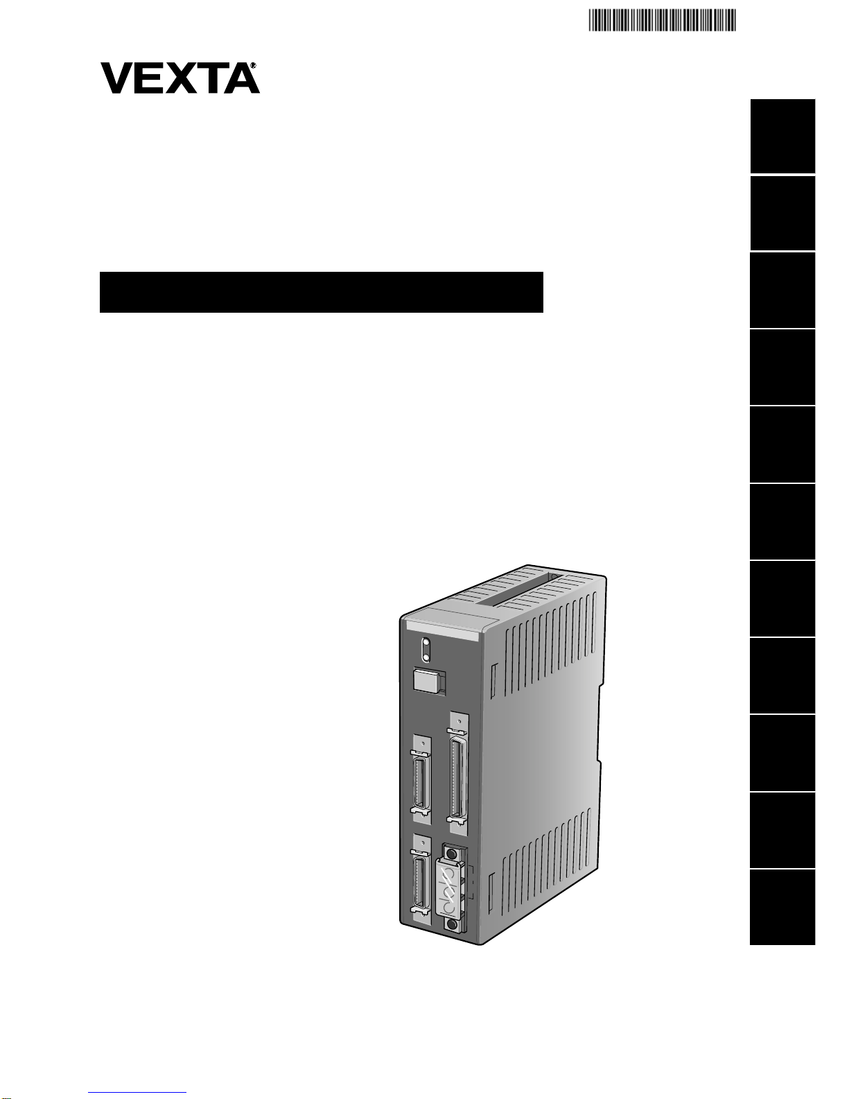
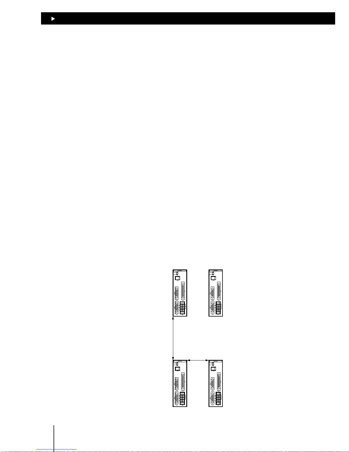
1.2 System configuration
A sample system configuration using the EMP400 series is provided below.
24 VDC power supply
(for I/O)
Host controller
24 VDC power supply
(for the main unit)
+24V
RS-232C
Modular cable
(option)
GND
+24V
GND
Personal computer
Driver
Motor or
Motorized slider
Driver
Motor or
Motorized slider
Data setter
(option)
∗ The unit cannot be used to write
a sequence program.
only
Page 9

2
Safety precautions
This section covers safety precautions to ensure safe operation of
the product.
Page 10

2
Safety precautions
2-2
2.1 Important Safety Instructions
Only qualified personnel should work with the product.
Use the product correctly after thoroughly reading the section “Safety precautions.”
The precautions described below are intended to prevent danger or injury to the user and other
personnel through safe, correct use of the product.
Use the product only after carefully reading and fully understanding these instructions.
Please read “Safety Precautions” in the Operating Manual for the motor you are using with this
product.
Warning
Handling the product without observing the instructions that accompany a “Warning” symbol may
result in serious injury or death.
Caution
Handling the product without observing the instructions that accompany a “Caution” symbol may
result in injury or property damage.
Note
The items under this heading contain important handling instructions that the user should observe to
ensure safe use of the product.
This contains information relative to the description provided in the main text.
Warning
General z Do not use the product in explosive or corrosive environments, in the presence of flammable
gases, locations subjected to splashing water, or near combustibles.
Doing so may result in fire or injury.
z Assign qualified personnel the task of installing, wiring, setting, operating/controlling, and inspecting
the product.
Failure to do so may result in fire, electric shock or injury.
Installation z Install the controller and data setter in enclosures in order to prevent injury.
Connection z Keep the controller’s input-power voltage within the specified range to avoid fire.
z For the controller’s input-power voltage within the specified range to avoid fire.
z Connect the cables securely according to the wiring example in order to prevent fire.
z Do not forcibly bend, pull or pinch the power cable.
Doing so may result in fire.
Operation z Turn off the driver power in the event of a power failure, or the motor may suddenly start when the
power is restored and may cause injury or damage to equipment.
z Stop the motor in the event the controller’s ALM (alarm) output is detected.
Failure to do so may result in fire or damaged driver.
Repair, disassembly and modification
z Do not disassemble or modify the controller.
Refer all such internal inspections and repairs to the branch or sales office from which you purchased
the product.
Page 11

2
Safety precautions
2-3
Caution
General z Do not use the controller beyond their specifications, or injury or damage to equipment may
result.
z Keep your fingers and objects out of the openings in the controller, or fire may result.
Installation z Keep the area around the controller, and data setter free of combustible materials in order to
prevent fire or a burn.
z To prevent the risk of damage to equipment, leave nothing around the controller and data setter
that would obstruct ventilation.
Operation z Use a controller and driver only in the specified combination. An incorrect combination may
cause a fire.
z To avoid injury, remain alert during operation so that the motor can be stopped immediately in an
emergency.
z Before switching on the controller, disconnect all of its output signals.
Failure to do so may cause the motor to start unexpectedly, resulting in fire or equipment damage.
z Set the speed and acceleration/deceleration rate well within the respective capacities in order to
prevent abrupt load fluctuations.
Failure to do so may cause the motor to misstep and the moving part to move in unexpected
directions, possibly resulting in injury or equipment damage.
z When an abnormality is noted, stop the operation immediately, or fire, or injury may occur.
Disposal z When disposing of the controller, treat them as ordinary industrial waste.
Page 12

2
Safety precautions
2-4
2.2 Precautions for use
This section covers limitations and requirements the user should consider when using the controller
EMP400 series and the data setter OP300.
Power capacity
For the controller, use a DC power supply capable of supplying 24VDC ±5% at 0.45A or greater, with
reinforced insulation provided on the primary and secondary sides.
Connecting the OP300 operational unit
Be sure to use the cable supplied with the OP300 operational unit when connecting it to the controller.
The cable comes with two ferrite cores intended for noise prevention. Do not remove these ferrite
cores, since doing so may diminish noise resistance and possibly cause a malfunction.
Preventing electrical noise
Take the following anti-noise measures to prevent malfunction of the controller, driver, and motor
due to external noise:
zz
zz
z Wiring the motor
Use an extension cable (sold separately) for connection between the driver and motor.
zz
zz
z Wiring the I/O cable
For I/O cables, use a shielded cables with connectors (sold separately).
Minimize the length of the I/O cable.
Wire the I/O cables by maintaining a minimum distance of 300mm (11.8in.) from the inductive loads
of electromagnetic relays, etc., as well as the power lines (the power source and motor, etc.) Do not
wire the I/O cables in the same duct or pipe in which power lines are wired.
zz
zz
z Connecting mains filter for power source line
Connect a mains filter to the AC power source input part of the driver in order to prevent externally
generated noise from being transmitted to the driver via the power-source line.
Ground the noise filter’s contact terminal using a cable of AWG16 (1.25mm
2
) or more in diameter.
The use of a cable smaller than AWG16 may cause heat generation.
Page 13

3
Preparations
This section covers the items that needs to be checked after
purchasing the product, along with the names, functions and main
specifications of components in the controller.
Page 14
33
33
3
Preparations
3-2
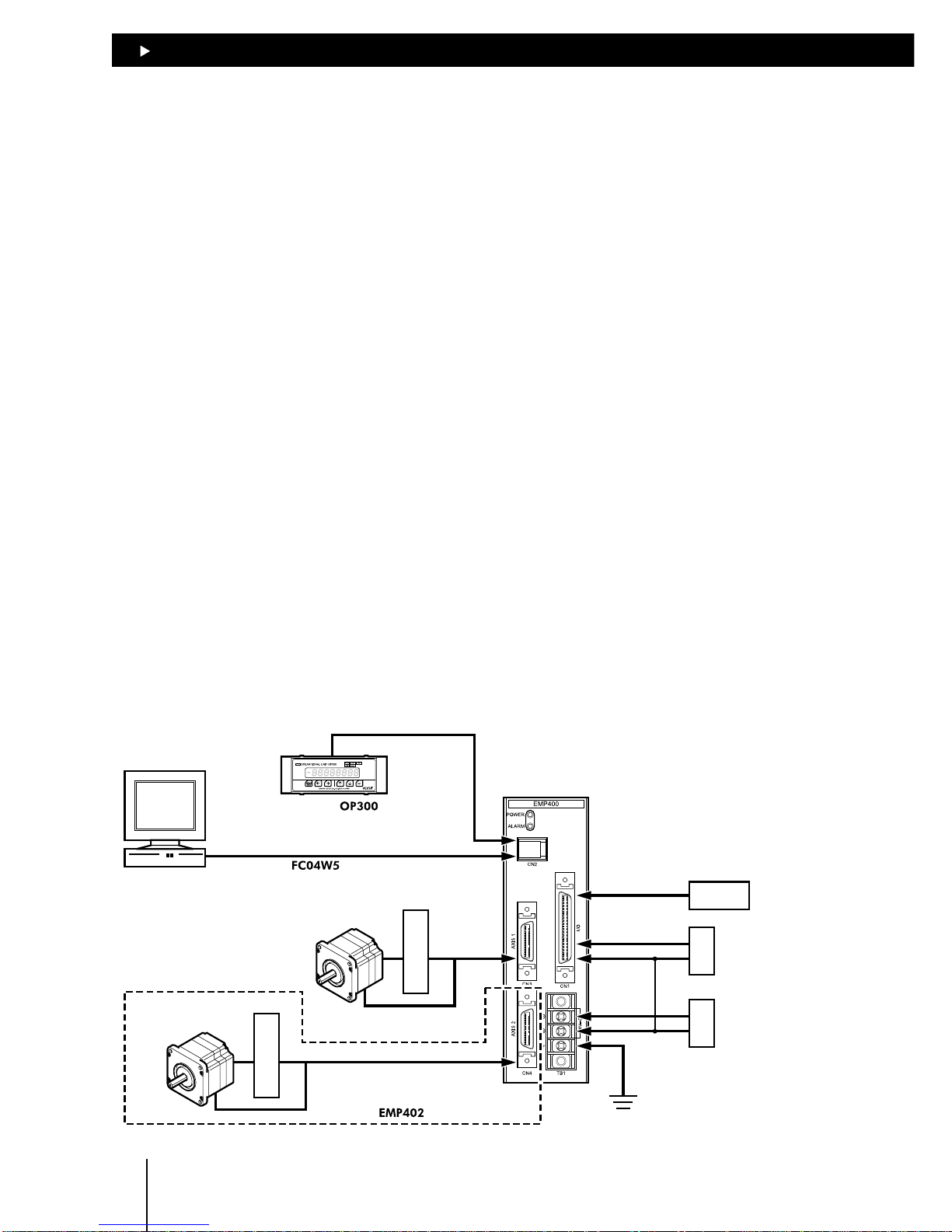
3.1 Checking the product
Upon opening the package, verify that the items listed below are included.
In case any of these items is missing or damaged, check the model number shown on the package
label and contact the branch or sales office from which you purchased the product.
C
N
1
C
N
3
C
N
2
C
N
4
24V DC
T
B
1
E
M
P
4
0
0
P
O
W
E
R
A
L
A
R
M
Series
Controller for servo motor and stepping motor
Thank you for purchasing an Oriental Motor product.
This Operating Manual describes product handling procedures and safety precautions.
l
Please read it thoroughly to ensure safe operation.
l
Always keep the manual where it is readily available.
OPERATING MANUAL
1
2
3
4
5
6
7
8
9
10
11
12
HP-19036
series controller 1 unit I/O connector (50 pins) 1 set
∗
and only
∗
and only
AXIS connector (26 pins)
1 set
2 set
Operating manual 1 copy Appendix 1 copy
Series
Controller for servo motor and stepping motor
UNIT
HP-19034-2
Model number Connector included Equivalent
I/O connector (50 pins) Connector 54306-5011 (MOLEX)
10150-3000VE (SUMITOMO 3M)
Cover 54331-0501 (MOLEX)
10350-52A0-008 (SUMITOMO 3M)
AXIS connector (26 pins) Connector 54306-2611 (MOLEX)
10126-3000VE (SUMITOMO 3M)
Cover 54331-0261 (MOLEX)
10326-52A0-008 (SUMITOMO 3M)
How to identify the product model
Connector
1: No connector
2: Solder type
series
Axis number
1: 1 axis
2: 2 axes
Page 15
33
33
3
Preparations
3-3
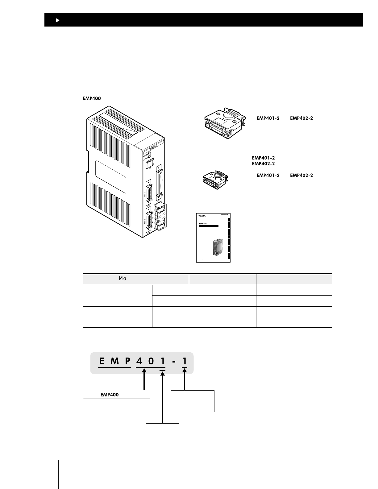
3.2 Names of parts
This section covers the names and functions of parts in the controller.
POWER LED
Lit when the power is on.
Terminal block (TB1)
Used to connect the 24VDC
power supply and frame ground.
ALARM LED
Lit when an alarm event occurs.
AXIS 1 connector (CN3)
Used to connect the first
axis I/O and sensor.
I/O connector (CN1)
Used for external-signal and
general-purpose inputs and outputs.
Modular connector (CN2)
Used to connect the cable for
communication with terminals
such as a PC and operational
unit.
AXIS 2 connector (CN4)
Used to connect the second
axis I/O and sensor.
∗Only
Page 16

33
33
3
Preparations
3-4
3.3 Specifications of EMP400 series
Control axis number 1 or 2
Number of sequence programs 32 (sequence programs 0 through 31)
The sequence program 99 is a CONFIG program.
Number of program lines 1,000 lines
Parameters Starting speed: 10 to 200kHz (1Hz increments)
Operating speed: 10 to 200kHz (1Hz increments)
Acceleration rate: 0.5 to 1,000ms/kHz (0.1ms/kHz increments)
Acceleration mode: Linear acceleration/deceleration, jerk limit control
Pulse count: ± 16,777,215 pulses
Pulse range -8,388,608 to 8,388,607 pulses
Operation mode Positioning operation (two-axis linear interpolation operation available
with EMP402 only)
Continuous operation
Mechanical home seeking operation
Mode for mechanical home Three-sensor mode (high-speed home seeking)
seeking Two-sensor mode (constant-speed home seeking)
Mechanical home seeking is possible via TIM or SLIT input
Data transmission format RS-232C based (3-wire)
General-purpose input 8 points, photocoupler inputs
General-purpose output 6 points, open-collector outputs, +5~24VDC, 25mA max. each
Power source 24VDC ± 5% at 0.45A min.
Page 17

4
Installation
This section covers the conditions and method for controller
installation.
Page 18
44
44
4
Installation
4-2
4.1 Location for installation
This controller is designed and manufactured for installation in equipment.
Since heat generated from the controller is dissipated via air convection, install the controller in a well
ventilated area that ensures easy maintenance.
The conditions of the installation location are as follows:
z Inside an enclosure that is installed indoors (provide vent holes)
z Operating ambient temperature 0°C to +50°C (+32°F to + 122°F) (non-freezing)
z Operating ambient humidity 20 to 85%, maximum (no condensation)
z Area that is free from an explosive nature or toxic gas (such as sulfuric gas) or liquid
z Area not exposed to direct sun
z Area free of excessive amount dust, iron particles or the like
z Area not subject to splashing water (storms, water droplets), oil (oil droplets) or other liquids
z Area free of excessive salt
z Area not subject to continuous vibration or excessive shocks
z Area free of excessive electromagnetic noise (from welders, power machinery, etc.)
z Area free of radioactive materials, magnetic fields or vacuum
4.2 Orientation
When installing the controller inside an enclosure, place it in a vertical orientation by mounting it on
a DIN rail or securing it with screws through the two mounting holes provided on the controller.
There must be a clearance of at least 25mm (0.98in.) and 50mm (1.97in.) in the horizontal and
verticaldirections, respectively, between the controller and the enclosure or other equipment within
the enclosure.
50mm (1.97in.) minimum
25mm (0.98in.) minimum
Page 19
44
44
4
Installation
4-3
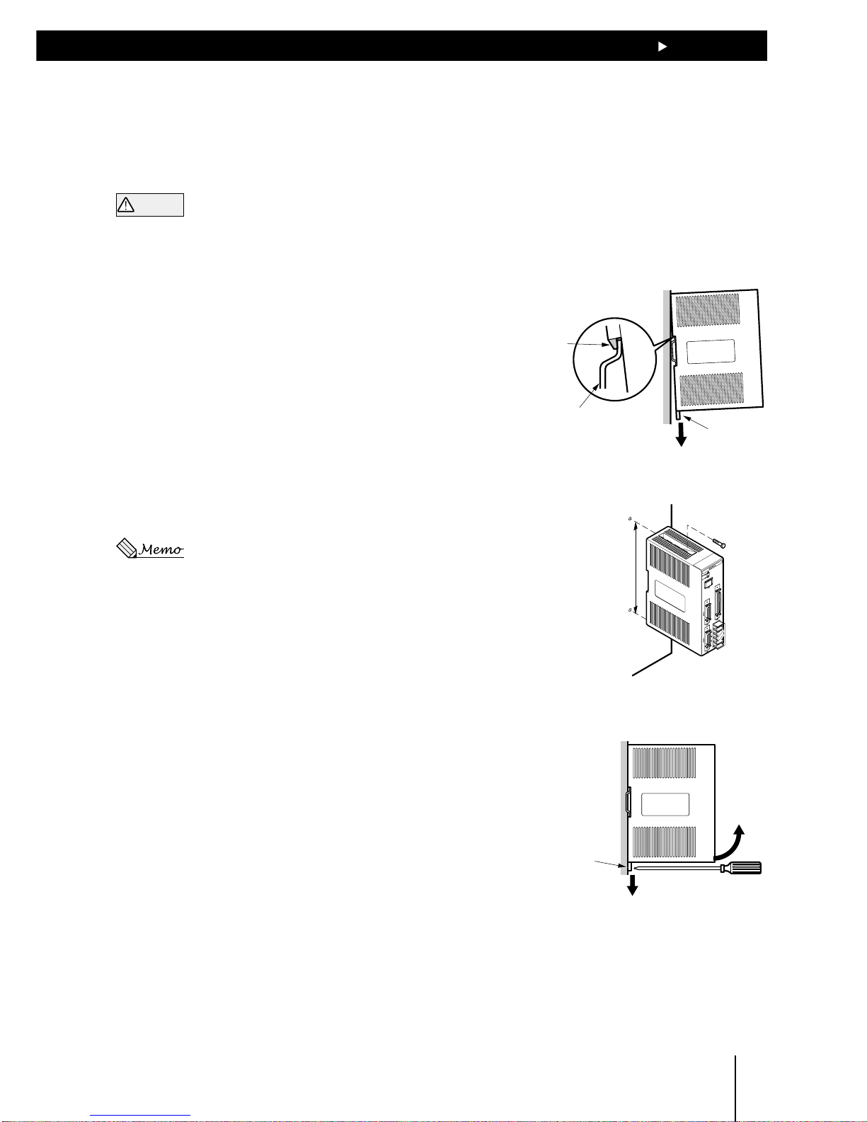
4.3 Installation method
Mount the controller on a DIN rail. In case the DIN rail produces significant vibrations, mount the
controller on an appropriate metal plate.
Warning
z
Do not place any equipment that generates excessive heat or noise in the vicinity of the controller.
z
Check and reexamine the means of ventilation if the ambient temperature of the controller exceeds
50°C (122°F).
Mounting the controller on a DIN rail
Use a DIN rail of 35mm (1.38in.) in width. Use the end
plates to secure the controller mounted on the DIN rail.
1. Engage the hook on the back of the controller over the
DIN rail by pulling down the controller’s DIN lever, and
push the controller until the DIN lever locks in place.
2. Secure each end of the controller using the end plates.
Installing the controller with screws
Install the controller on a metal plate and secure it using
two screws (M3 or M4, two pieces).
There should be no gap between the controller and plate.
The screws are not included in the package.
Removing the controller from the DIN rail
125±0.1mm
(4.92±0.004in.)
1. Use a flat-head screwdriver to pull down the DIN lever
until it locks in place.
Pull the DIN lever with a force of 10 to 20N (2.2 to
4.41lb.).
Applying excessive force may damage the DIN lever.
2. Raise the controller upward to remove from the DIN
rail.
Tab
DIN rail
DIN lever
DIN lever
Page 20

44
44
4
Installation
4-4
Page 21

5
Connection
This section covers the methods for connecting the power, driver,
host controller and other units to the EMP400 Series controller, as
well as the grounding method, input/output circuits and a
connection example.
Page 22
55
55
5
Connection
5-2
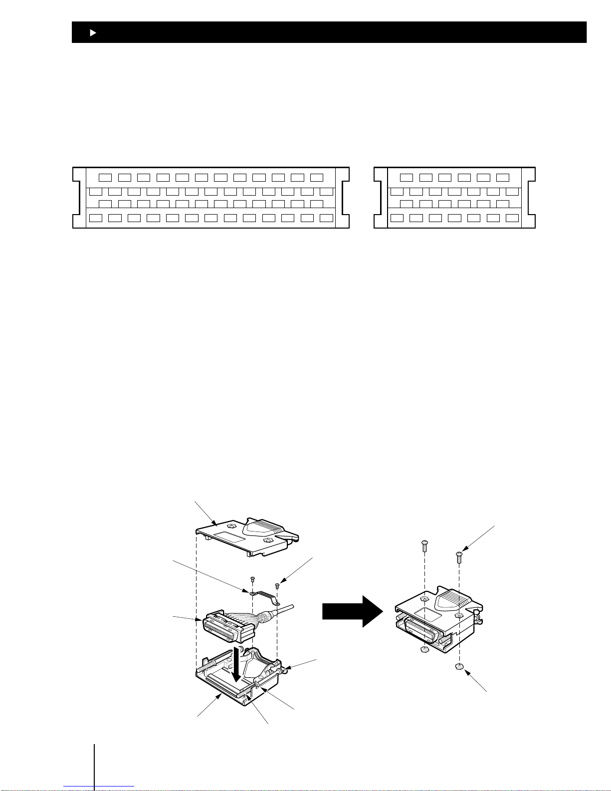
5.1 Assembling the connector
Solder-type connectors are supplied with the EMP401-2 and EMP402-2 series controllers.
Solder the host controller cable for the I/O connector and the driver cable for the AXIS connector.
The following figure shows the pin arrangement of the connector.(Viewed from the soldering side)
1
26
25
50
2
135791113151719212325
4681012141618202224
27
26283032343638404244464850
2931333537394143454749
1
14
13
26
2
135791113
4681012
15
14161820222426
1719212325
I/O connector AXIS connector
1 Solder a cable to the half-pitch connector.
The cable is not included in the package. Use a multi-core, overall-shielded, twisted-pair cable
of AWG28 (0.08mm
2
) or more in diameter.
2 Place the screws (M2.5, two pieces) supplied with the connector in the bottom connector cover.
Place the screws so that their flat washers align with the indents in the connector cover and the
spring washers sit on the outside of the connector cover.
3 Place the connector with the cable in the bottom connector cover and screw the cable mounting
bracket.
Tighten the mounting bracket screws (M2, two pieces) to the specified torque.
Torque: 0.3 to 0.35N·m (42.6 to 49.7oz-in)
4 Place the top connector cover and assemble the top and bottom connector covers using the
supplied screws (M2.5, two pieces) with hexagonal nuts.
Tighten the connector cover screws to the specified torque.
Torque: 0.5 to 0.55N·m (71 to 78.1oz-in)
Top connector cover
Bottom connector cover
Connector
Cable mounting
bracket
Screws for cable
mounting bracket
(M2, two pieces)
Screw for
connector cover
(M2.5, two pieces)
Hexagonal nut
Spring
washer
Flat washer
Screw (M2.5, two pieces)
Page 23
55
55
5
Connection
5-3
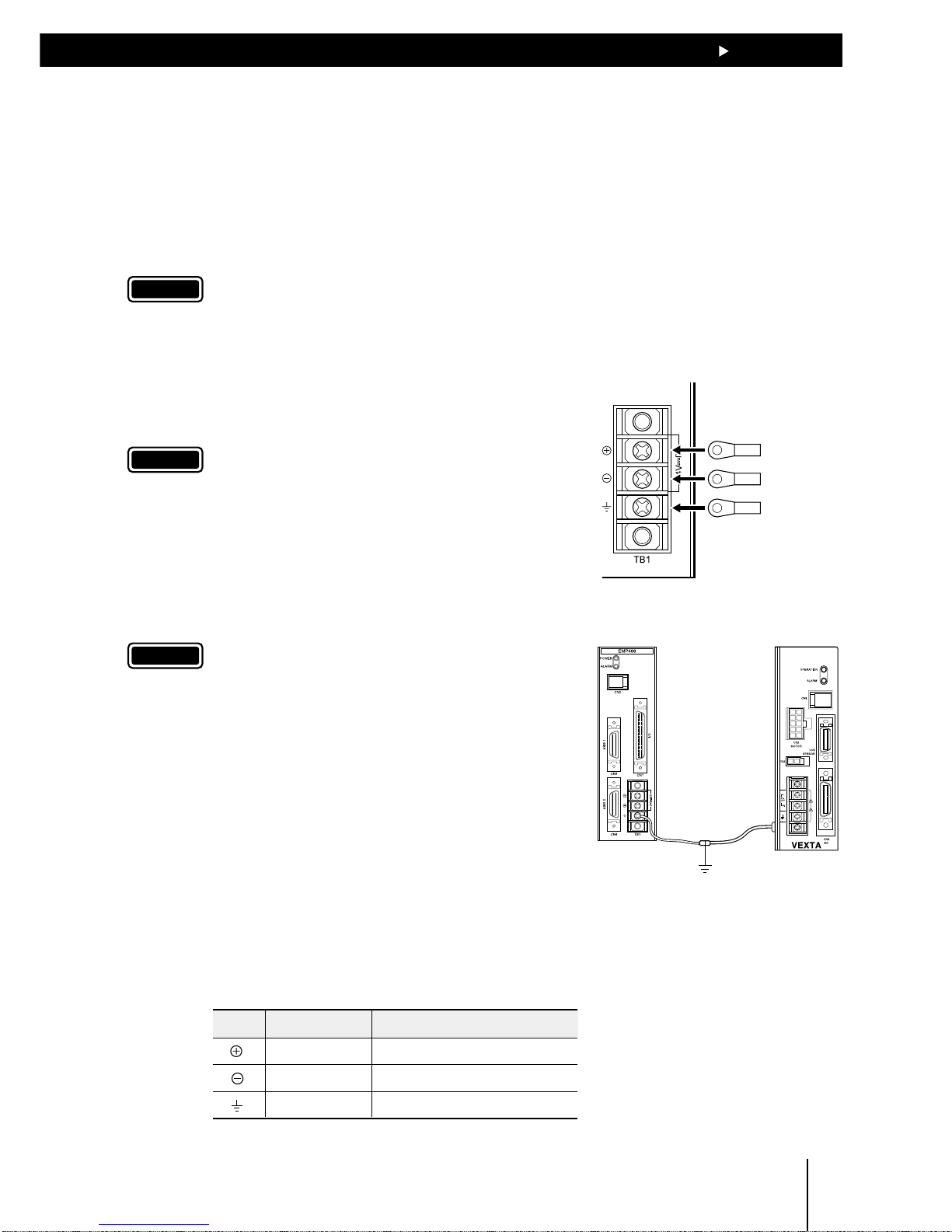
5.2 Connecting to the power supply
The controller’s power supply is connected to the TB1 terminals. In addition to the power-supply
terminals, TB1 has a frame ground (FG) terminal to prevent malfunctions caused by external noise.
The power supply provides a voltage of 24VDC ± 5% with current consumption of 0.45A max. The
current consumption level includes the current supplied to the operational unit.
Use round, insulated crimp terminals for power and grounding cables.
Note
The power supply should be designed to provide ample capacity. Insufficient power capacity may
cause an error in the controller operation.
24VDC/+ terminal
24VDC/
-
terminal
FG terminal
Grounded at
one point
Controller Driver
1. Remove the terminal cover from TB1.
2. Remove the positive and negative terminal screws, then
connect the 24VDC power cable.
Verify that the connection has the proper polarity.
Note
For the power cable, use the cable of AWG20 (0.5mm2) or
more in diameter. Any cable with a smaller diameter
may cause heat generation.
3. Tighten terminal screws at a tightening
torque of 0.5N·m (71oz-in).
4. Remove the FG terminal screws and connect the
grounding cable.
Note
For the power cable, use the cable of AWG18 (0.75mm2)
or more in diameter. Any cable with a smaller diameter
may cause heat generation.
5. Tighten terminal screws at a tightening
torque of 0.5N·m (71oz-in).
6. Secure the grounding cable connected to the FG
terminal to the ground point, using screws with an inner
clip washer.
The above grounding cable should be grounded at one
point together with the grounding cable connected to
the driver’s protective earth terminal.
7. Place the terminal cover on TB1.
TB1 signals
Symbol Signal Description
+24V power Input terminal of the power supply
GND Ground of the power supply
FG Frame ground
Page 24
55
55
5
Connection
5-4
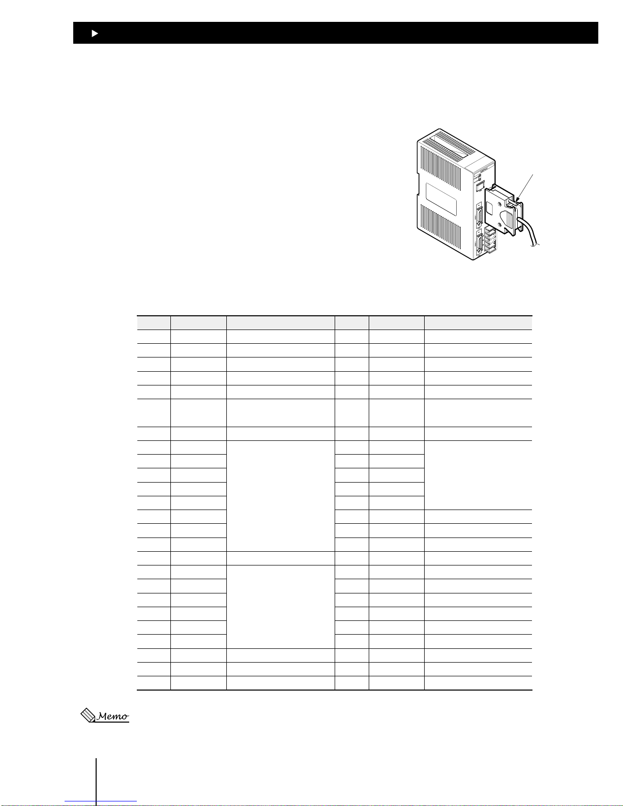
5.3 Connecting the host controller (CN1)
CN1 (I/O) signal table
Pin No. Signal Description Pin No. Signal Description
1
− No connection
26
− No connection
2
E-STOP input Emergency stop
*1
27
ALM output Alarm
3 START input Execution of a program 28
−
No connection
4 S-STOP input Interruption of a program 29 MOVE output During pulse generation
5
− No connection
30
− No connection
6
− No connection
31
READY output
Ready to accept START
input
7
+COM input
Power source for I/O (+24V)
*2
32
+COM input
Power source for I/O (+24V)
*2
8
IN1 input
General input
33
M0 input
Selection of
program number
9
IN2 input
34
M1 input
10
IN3 input
35
M2 input
11
IN4 input
36
M3 input
12
IN5 input
37
M4 input
13
IN6 input
38
− No connection
14
IN7 input
39
− No connection
15
IN8 input
40
− No connection
16
+COM input I/O (+24V)
*2
41
− No connection
17
OUT1 output
General output
42
− No connection
18
OUT2 output
43
− No connection
19
OUT3 output
44
− No connection
20
OUT4 output
45
− No connection
21
OUT5 output
46
− No connection
22
OUT6 output
47
− No connection
23
− No connection
48
− No connection
24
− No connection
49
END output Positioning complete
25
-
COM input
Power source for I/O (GND)
*2
50
-
COM input
Power source for I/O (GND)
*2
∗1:The E-STOP input is at normally closed. (The state of the contact is given when the photocoupler is turned
off.)
∗2:+COM and -COM inputs are shared internally.
5.3.1 Connection method
Use the I/O connector (50-pin) for connection with the host
controller.
Plug the I/O connector into CN1 and tighten the screw.
Screw
Page 25

55
55
5
Connection
5-5
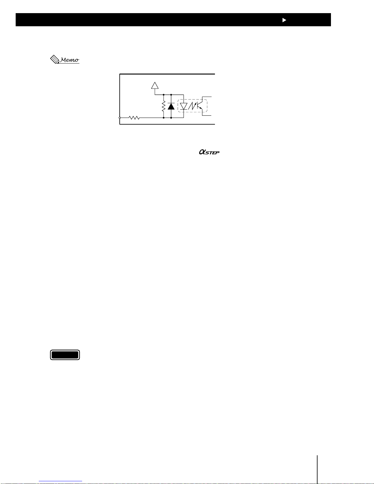
5.3.2 Internal input circuit
The signal state represents the “ON: Carrying current” or “OFF: Not carrying current” state of the internal
photocoupler rather than the voltage level of the signal.
5.4k
820
PS2801 or
equivalent
+COM
E-STOP, START
S-STOP, IN1 to IN8
M0 to M4
zz
zz
z E-STOP input
This terminal is used to input the emergency stop signal.
The E-STOP input is a normally closed. Input is enabled when the E-STOP is turned off, immediately
stopping pulse output and stopping the motor. The program stops, also.
In the normal state, be sure to connect the E-STOP input to GND to keep it on.
zz
zz
z START input
This terminal is used to input the signal for starting the program.
The program is executed once the START input is turned on.
zz
zz
z S-STOP input
This terminal is used to input the signal for stopping the operation.
The program is stopped once the S-STOP input is turned on. If the S-STOP input is turned
on while the motor is in operation, the motor will decelerate to a stop.
Once operation resumes, the program will start over from the beginning.
zz
zz
z IN1 to IN8 inputs
General-purpose input terminals
zz
zz
z M0 to M4 inputs
Terminals for choosing the program to be used through unique combinations of the M0 to M4 input
states. For more information about the selection of programs through combinations of M0 to M4
input states, see section 7.2, “Program execution via the host controller.”
Page 26
55
55
5
Connection
5-6
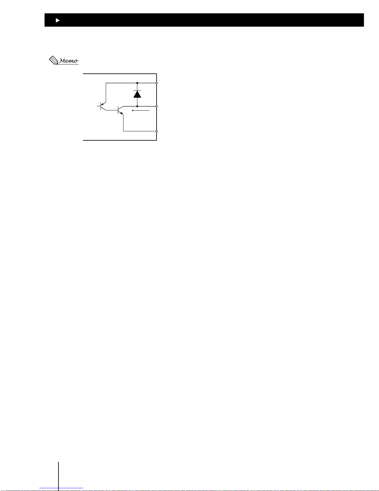
5.3.3 Internal output circuit
The signal state represents the “ON: Carrying current” or “OFF: Not carrying current” state of the internal
photocoupler rather than the voltage level of the signal.
TD62004AF
or equivalent
+COM
+5〜24VDC
25mA max.
-
COM
ALM, MOVE, READY
OUT1 to OUT6, END
zz
zz
z ALM output
The ALM output is turned on when the E-STOP input is turned off, an alarm input is fed from the
driver or there is an error in the controller.
Once the problem’s cause is eliminated, the ALM output is cancelled automatically. For more
information on the causes and handling of alarms, see section 10.1, “When ALARM LED illuminates.”
The output logic may be switched between normally open and normally closed via command inputs.
(Set to “normally closed” at the time of power-on.)
z MOVE output
The MOVE output is turned on during pulse output.
z READY output
The READY output is turned on when the controller is ready to accept the START input.
The READY output is turned off while the program is being executed or modified.
z OUT1 to OUT6 outputs
General-purpose outputs
z END output
One-shot output will be performed after a positioning operation.
The amount of output time can be changed via command input. (Set to 10ms at the time of poweron.) If END input from the driver is set to “used” via command input, pulse output from the controller
will cease. When the END input from the driver turns on, END output also turns on.
Page 27
55
55
5
Connection
5-7
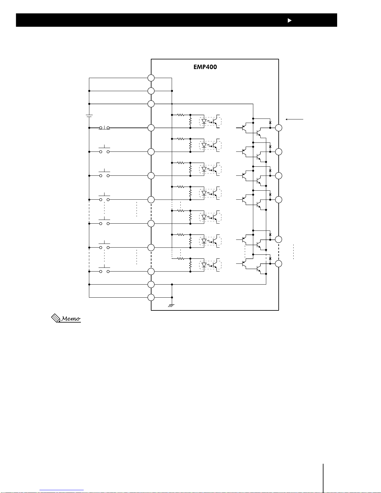
5.3.4 Connection example to a host controller
Series
CN1
7
16
32
2
3
4
33
37
8
15
25
50
27
29
31
49
17
22
ALM output
MOVE output
READY output
END output
OUT1 output
OUT6 output
E-STOP input
24VDC
+COM input
+COM input
+COM input
-
COM input
-
COM input
START input
S-STOP input
M0 input
M4 input
IN1 input
IN8 input
+5~24VDC
25mA max.
The current flow for each output signal is 25mA or less.
Page 28
55
55
5
Connection
5-8
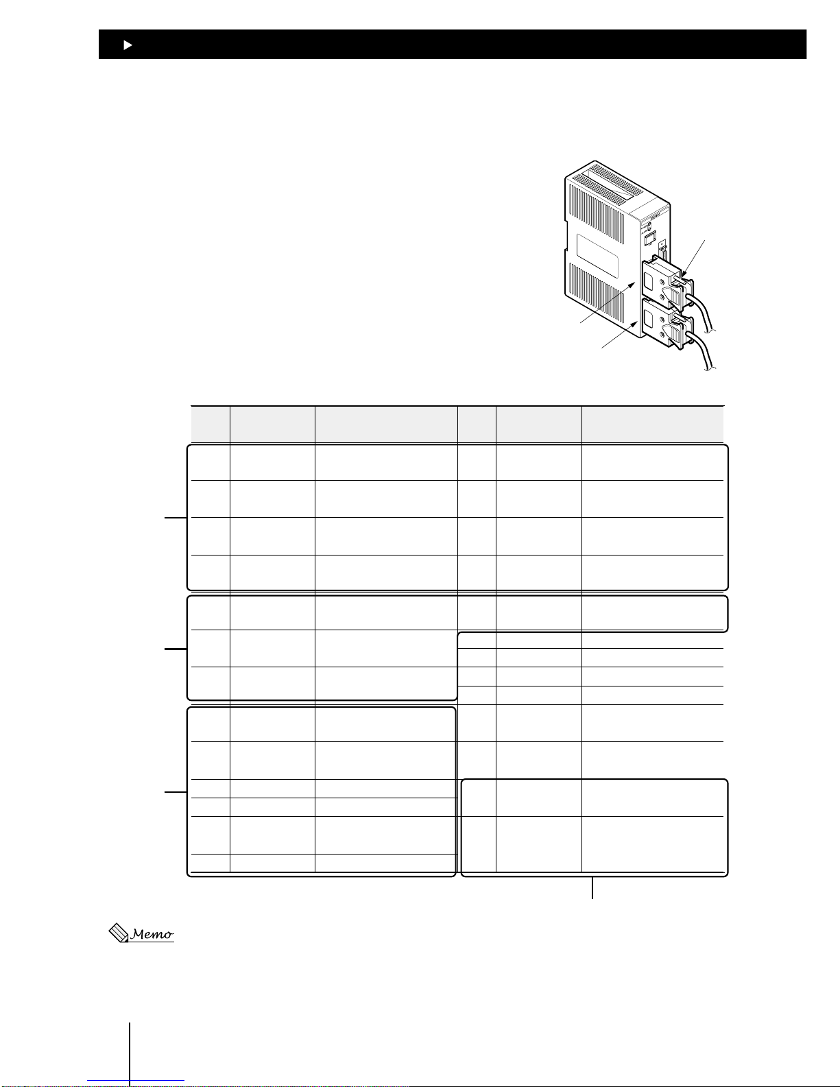
5.4 Connecting the driver (CN3·CN4
∗EMP402 only
)
5.4.1 Connection method
Use the AXIS connector (26-pin) for connection with the
driver.
Plug the AXIS connectors for the first- and second-axis
drivers into CN3 and CN4, respectively, and tighten them
with screws.
Screw
CN3
CN4
CN3·CN4 signal table
Pin
No.
Signal Description
Pin
No.
Signal Description
1
+CW-P output
(+PULSE output)
CW pulse (pulse)
14
-
No connection
2
-
CW-P output
(-PULSE output)
CW pulse (pulse)
15
-
No connection
3
+CCW-P output
(+DIR output)
CCW pulse
(Direction of rotation)
16
+CCR output Counter-clear
4
-
CCW-P output
(-DIR output)
CCW pulse
(Direction of rotation)
17
-
CCR output Counter-clear
5
END input END signal from driver
18
GND
GND signal from driver
6
TIM input
Timing signal from driver
7
ALM input
Alarm signal from driver
8
+LS input
CW limit sensor
19
-
No connection
9
-
LS input CCW limit sensor
20
-
No connection
10
HOMELS input Home limit sensor
21
-
No connection
11
SLIT input Slit sensor
22
-
No connection
12
+12V output
Power source terminal
for sensor (35mA max.)
23
-
No connection
13
GND GND for sensor
24
-
No connection
25
+5V output
Power source terminal for
timing signal (20mA max.)
26
GND GND for timing signal
Outputs to
driver
Inputs from
driver
SENSOR
For timing signals
Shown in parentheses is the information for 1-pulse output mode.
Page 29
55
55
5
Connection
5-9
5.4.2 Internal input circuit
The signal state represents the “ON: Carrying current” or “OFF: Not carrying current” state of the internal
photocoupler rather than the voltage level of the signal.
2.7kΩ
1kΩ
PS2801 or
equivalent
+12V
END, TIM, ALM
+LS,
-
LS
HOMELS, SLIT
z END input
This terminal is used to input the END signal output from the driver at the end of operation. This
terminal should be connected when using the
or servo motor.
The END signal is enabled or disabled via command input. (Set to “enabled” at the time of poweron.)
z TIM input
This terminal is used to input the timing signal from the driver.
When mechanical home is detected in mechanical home seeking mode, an accurate home position
can be found by using this signal with the HOMELS input or the HOMELS input/TIM input by
connecting them with an AND logic operator.
z ALM input
This terminal is used to input the alarm signal from the driver. (The driver’s alarm outputs may either
be at normally open or normally closed, depending on the model.)
If an alarm-signal input is fed while the motor is in operation, the motor will decelerate to a stop and
the program will stop also.
No pulse can be output while alarm signal inputs are being fed, although any command not associated
with pulse output can be executed.
The input logic may be switched between normally open and normally closed via command inputs.
(Set to “normally closed” at the time of power-on.)
z +LS and –LS inputs
This terminal is used to input signals from +LS and –LS.
If the LS input is turned on during pulse output, the motor will stop immediately. However, mechanical
home seeking will continue even if the LS input is turned on.
The input logic may be switched between normally open and normally closed via command inputs.
(Set to “normally open” at the time of power-on.)
Note
Note that two different input logics cannot be set for the +LS and –LS inputs, respectively.
z HOMELS input
This terminal is used to input signals from HOMELS when performing high-speed home seeking
using three sensors.
The input logic may be switched between normally open and normally closed via command inputs.
(Set to “normally open” at the time of power-on.)
z SLIT input
This terminal is connected when using a motorized slider with a slit sensor.
An accurate home position can be found by using this signal with the HOMELS input or the HOMELS
input/TIM input by connecting them with an AND logic operator.
The input logic may be switched between normally open and normally closed via command inputs.
(Set to “normally open” at the time of power-on.)
Page 30
55
55
5
Connection
5-10
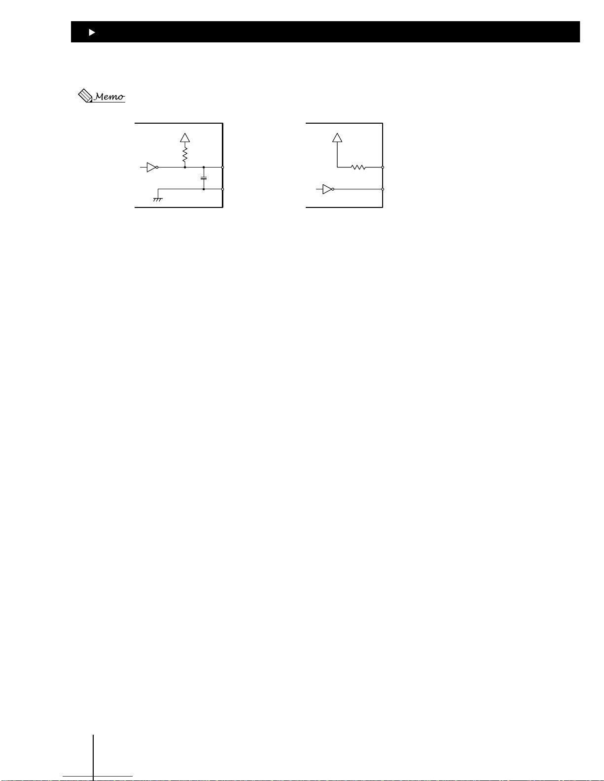
5.4.3 Internal output circuit
The signal state represents the “ON: Carrying current” or “OFF: Not carrying current” state of the internal
photocoupler rather than the voltage level of the signal.
+12V +12V
560Ω
74LS06 or
equivalent
1000pF
+CW-P (+PULSE)
+CCW-P (+DIR)
-
CW-P (-PULSE)
-
CCW-P (-DIR)
560Ω
74LS06 or equivalent
+CCR
-
CCR
z±CW-P (±PULSE) output, ±CCW-P (±DIR) output
These terminals are used to output pulses.
Information in parentheses is for 1-pulse output mode. In the 1-pulse output mode, the motor will
rotate in the CW direction with the DIR output turned on and in the CCW direction with the DIR output
turned off.
The output mode may be switched between 1-pulse and 2-pulse modes via the PULSE command.
(Set to “2-pulse mode” at the time of power-on.)
z ±CCR output
These terminals are used to output counter clear signals for resetting the counter in the driver.
These terminals should be connected when a servo motor is used.
The circuit will generate CCR outputs in any of the following situations (output width 500µs):
• The E-STOP input is turned off while the motor is in operation
• While mechanical home seeking is in progress
• When the motor has pulled out from the limit sensor during continuous operation
• When an alarm event has caused the operation to stop immediately
• When the power is turned on or the RESET command is input
Page 31

55
55
5
Connection
5-11
5.4.4 Connection example to a driver
series
CN3・CN4
Driver
15
6
7
8
9
10
11
2
3
4
16
17
25
26
12
13
18
+5V output/Power source f or TIM
∗
5
(20mA max.)
GND∗5
+12V output
GND
GND
+CCR output∗4
-
CCR output∗4
+CCW-P output
-
CCW-P output
+CW-P output
-
CW-P output
Power source
for sensor
(140mA max.)
SLIT input∗3
END input*1
+12V
+12V
+12V
+5V
+12V
TIM input*2
ALM input
+LS input
-
LS input
HOMELS input
+CW-P input
-
CW-P input
+CCW-P input
END output
TIM output
ALM output
COM
-
CCW-P input
+CCR input
-
CCR input
Power source
for TIM
Vcc+5V
GND
∗1: Connect the END input (5-pin) when using an or servo motor.
∗2: Do not connect the TIM input (6-pin) when using a servo motor.
∗3: Connect the SLIT input (11-pin) when using a motorized slider with a slit sensor.
∗4: Connect the CCR output (16/17-pin) when using a servo motor.
∗5: Connect the timing-signal power supply (25/26-pin) to the driver when using the TIM output with an
motor.
Page 32

55
55
5
Connection
5-12
CN2
5.5 Terminal connection (CN2)
5.5.1 Connection method
Modular cables are used to connect a PC and the
operational unit.
Plug the modular cable connector into CN2.
Page 33

6
Writing and editing
a program
This section covers how to write a sequence program and edit an
existing sequence program.
Page 34

6 Writing and editing a program
6-2
6.1 How to write a program
The program contains the method of motor operation as well as speed settings and other
parameters.
Once the program is started, the motor will execute the commands contained in the program
according to a specified order.
The program is stored in the controller memory.
A program can be written using one of the following two methods:
Using a line editor
Input commands
using a line editor.
Send a command at
each press of the key.
[Procedure]
1. Connect the controller with a PC.
(See section 6.3, “Starting and exiting HyperTerminal.”)
2. Use a line editor to save commands to the controller in real time.
Each time the Enter key is pressed following command input, the command is sent to the controller.
(See section 6.4, “Writing a program with a line editor.”)
Using a text editor
Write a program
using a text editor.
Download the program.
[Procedure]
1. Write a program using a text editor, then save it in text format.
(See section 6.5, “Writing a program with a text editor.”)
2. Connect the controller with a PC.
(See section 6.3, “Starting and exiting HyperTerminal.”)
3. Download the program in the text-format file to the controller.
(See section 6.5.2, “Downloading a program.”)
Page 35

6 Writing and editing a program
6-3
6.2 Additional information on program
composition
6.2.1 Program
• A program is composed of commands to the controller and parameters.
• Type in alphanumeric characters (case-insensitive) to define commands and parameters for the
program.
• The character string containing a command and parameters is called “line.” One line can only
contain one command.
T I M 2
,
1
,
0
Axis set parameter
No space is necessary between an
axis set parameter and a command.
(Separating them with a space will result in an error.)
Parameter
Space or comma
A space or comma should be used to
delimit parameters or a command
and a parameter.
Command
A maximum of 32 sequence programs can be created, from program numbers 0 through 31.
Additionally, program number 99 can be written as an automatically executable program. (See
section 7.3, “Automatic program execution.”)
A total of 1000 lines can be configured for these 33 programs.
Example 1: 125 lines x 8 programs = 1,000 lines
Example 2: 500 lines x 2 programs = 1,000 lines
6.2.2 Parameter settings for motor operation
Correct settings for sensors and drivers should be defined before operating the motor.
Settings are required for the following parameters. For further details, see 8.2.1, “Hardware
configuration commands.”
• Pulse output mode setting............................................................... PULSE command
• ID setting ......................................................................................... ID command
• Setting for +/
-
LS input, HOMELS input or SLIT input logic............ ACTL command
• Input logic setting for alarm input from the driver ............................ ACTL command
• Setting for alarm output logic...........................................................ACTL command
• Home detection method setting ...................................................... SEN command
• END input usage .............................................................................EEN command
• TIM input usage............................................................................... TIM command
• SLIT input usage .............................................................................TIM command
• Unit-value setting............................................................................. UNIT command
Page 36

6 Writing and editing a program
6-4
6.3 Starting and exiting HyperTerminal
6.3.1 Verifying the communication method
1. Start the PC and open “System” in the control panel.
The System window then appears.
2. Select the “Device Manager” tab.
The Device window then appears.
3. Verify that there is “Communication Port (COM∗)” under “Port.”
If there is no “Communication Port (COM∗),” read the operating manual for your computer and
set up a serial communication function.
Page 37

6 Writing and editing a program
6-5
6.3.2 How to start HyperTerminal
1. Switch off the power to the controller.
2. Connect the controller’s CN2 with your computer using the optional FC04W5 modular cable
(purchased separately).
3. Start the computer.
4. Click on the “Start,” “Program,” “Accessories,” “Communication” and “HyperTerminal” icons to
start Hyper Treminal.
A window appears with a slot, where a name can be typed in for the new connection.
Page 38

6 Writing and editing a program
6-6
5. Type in a name for the connection (e.g. EMP400), then select an icon and click “OK.”
A window appears, asking you to enter information regarding the telephone number.
6. In a typical connection method you may select the communication port you have previously
verified as described in section 6.3.1, “Verifying the communication method,” and click “OK.”
A window appears in which to set properties.
Note
The connection method may vary, depending on the computer.
For details, see the operating manual for your computer.
7. Set properties as follows:
• Bits per second: 9600 bps
• Data bit: 8
• Parity: None
• Stop bit: 1
• Flow control: None
Page 39

6 Writing and editing a program
6-7
8. Click “OK.”
The selected connection is saved and the HyperTerminal screen appears.
9. Power on the controller.
The HyperTerminal screen indicates that the controller has started up.
The connection settings are required only before the initial connection.
Page 40

6 Writing and editing a program
6-8
6.3.3 How to exit HyperTerminal
1. Exit HyperTerminal.
A message appears, asking if you want to disconnect.
2. Click “Yes.”
A message appears, asking if you want to save the settings.
3. Click “Yes.”
The settings are saved and an icon is created.
Saving of the settings is required only after the initial connection.
For subsequent connections, you may start HyperTerminal simply by double-clicking the icon.
EMP400
Page 41

6 Writing and editing a program
6-9
6.4 Writing a program with a line editor
HyperTerminal (Windows application) can be used as a line editor to write a program.
While using HyperTerminal, command inputs to HyperTerminal are saved to the controller in real
time.
1. See section 6.3, “Starting and exiting HyperTerminal,” to connect the controller with your computer
and start HyperTerminal.
2. Type in “EDIT∗” (∗ represents a program).
Insert a space between “EDIT” and the program number.
Once the entry is made, a message “Empty... Direct Insert Mode” appears, indicating that the
program is empty. You can now write a new program.
3. See section 8, “Communication command,” to enter commands and parameters in order to write
a program.
The example program below shows the program number 1 specifying astarting speed of 100Hz,
operating speed of 3,000Hz, distance of 6,000 pulses and + (CW) direction.
To complete the writing of a program, type in “Q” or press the ESC key.
Page 42

6 Writing and editing a program
6-10
When an error message appears
An error message is displayed if any invalid command or parameter is entered while the sequence
program is being created.
If an error message appears, see section 6.7, “List of messages associated with programs,” for the
appropriate corrective action.
6.5 Writing a program with a text editor
A program may be written using a text editor on your PC.
The program should then be saved in text format for downloading to the controller via HyperTerminal’s
transmission function.
The downloaded program will be saved in the controller memory.
The program saved in the controller may also be uploaded to a PC via HyperTerminal’s transmission
function and saved in text format.
Controller
PC
Downloading
Uploading
Page 43

6 Writing and editing a program
6-11
6.5.1 How to write a program
There is a set of requirements that must be satisfied when writing a program using a text editor.
These requirements are explained in the following example of program composition.
1. Start a text editor.
2. Write a program by meeting the requirements explained below.
Type in alphanumeric characters.
Up to 80 characters may be entered for each line.
[Requirements]
∗1. The program should start with “Seq∗” (∗ represents
a program number). Enter a space between
“Seq” and the program number.
∗2. Enter the line number in brackets “[ ].”
∗3. No more than one command can be entered into a
single line.
∗4. Following the last line of the program, be sure to
press the Enter key at least once.
∗5. One text file can contain more than one program.
∗6. The line number may be omitted. A space may be
entered.
∗7. Any character string entered following “ ; ” will be a
comment. The comment will not be saved in the
controller.
3. Save the created program in text format.
Always add the “.txt” extension to the text file name.
Downloading the file you created and saved in text
format in Step 2 to the controller and then uploading it
to a PC will result in the following:
[Results]
∗3. An error has occurred, since more than one
command was entered into one step.
∗4. Blank steps have been deleted.
∗6. An [n] representing the line number has been
added. A space has been deleted.
∗7. A comment has been deleted.
Seq 1
[1] LOOP 10
[2] VS 100
[3] V 3000, TR 30
[4] D 1000
[5] INC
[6] ENDL
Seq 2
LOOP 10
VS 100
V 3000
D 1000
inc
;comment
ENDL
Seq 1
[1] LOOP 10
[2] VS1 100
[3] syntax error
[4] D1 1000
[5] INC1
[6] ENDL
Seq 2
[1] LOOP 10
[2] VS1 100
[3] V1 3000
[4] D1 1000
[5] INC1
[6] ENDL
∗2
∗1
∗4
∗5
∗7
∗3
∗6
∗4
∗3
∗7
∗6
Page 44

6 Writing and editing a program
6-12
6.5.2 Downloading a program
The program saved in a PC can be downloaded to the controller using HyperTerminal.
Only programs in text format are downloadable.
Note
To download a program, exit all applications other than HyperTerminal. If you attempt to download
the program while running other applications, the motor may move abruptly.
1. See section 6.3, “Starting and exiting HyperTerminal,” to connect the controller with a PC and
start HyperTerminal.
2. Type in the download command “DWNLD” and press the Enter key.
It’s now ready to download.
3. Select “Send text file” from the “Transfer” menu of HyperTerminal.
A window appears with a slot to specify the file to be downloaded to the controller.
Only text files are downloadable.
Page 45

6 Writing and editing a program
6-13
4. Enter the name of the file you want to download, then click on “Open.”
Downloading of the program begins.
Once downloading is complete, the “Completed” message appears.
Note
Do not use the keyboard while the sequence program is being downloaded. Doing so may result in
a download error.
The numbers of the program and line in which the first downloading error was detected will be
displayed. (The figure below shows an example in which the first error was detected in Line
5 of Program 1.)
The command and parameters of the error line will be cancelled, and subsequent lines will be
correctly received by the controller. Since no command exists in the cancelled line, the error
program, if executed, will be halted at the cancelled line. Correct any error program and repeat
the download.
Note
You cannot overwrite an existing program. To replace the existing program with a new one, first
delete the applicable program saved in the controller and assign the same program number to the
new program before downloading it to the controller.
z You can download several sequence programs at once by writing and saving them in a single text file.
z If the same program number is assigned for more than one program within a single text file, the first program
downloaded will be enabled with the remaining programs cancelled.
Page 46

6 Writing and editing a program
6-14
6.5.3 Uploading a program
The program saved in the controller may be uploaded to a PC via HyperTerminal’stransmission
function.
The uploaded program will then be saved to a specified file in text format.
Either one or all of the programs can be uploaded at once.
1. See section 6.3, “Starting and exiting HyperTerminal,” to connect the controller with a PC and
start HyperTerminal.
2. Start a text editor.
3. Create and save a new text file.
Add the “.txt” extension to the text file name. Do not make any entry to the file.
4. Switch on the power to the controller.
The HyperTerminal screen will indicate that the controller has been started.
5. Type in the upload command “UPLD” and press the Enter key.
A message appears, prompting you to select a sequence program (Select upload Sequence No.
0-31, 99, ALL).
Page 47

6 Writing and editing a program
6-15
6. Select a program for uploading to the PC.
Type in a desired number from among “0” through “31” and “99” to specify one sequence program
number, or type in “A” to upload all of the sequence programs. Then, press the Enter key.
A message appears, prompting you to select text capture (Start “TEXT CAPTURE”).
7. Select “Capture Text” from the “Transfer” menu of HyperTerminal.
The Text Capture window appears.
8. Click on “Browse.”
A window appears to specify the file name and the folder under which to save the file.
9. Specify the text file saved in step 3 and click on “Save.”
The Text Capture window appears.
Page 48

6 Writing and editing a program
6-16
10. Click on “Start.”
The HyperTerminal screen appears.
11. Press the Enter key.
The controller begins uploading the program.
Once uploading is complete, a message (End “TEXT CAPTURE”) appears.
Note
Do not use the keyboard while the program is being uploaded.
Doing so may result in an upload error.
12. Select “Capture Text” from the “Transfer” menu of HyperTerminal, then select “Stop.”
This ends the Text Capture function.
13. Press the Enter key.
The “0>” command prompt is displayed.
14. Open the text file you saved and check to see that the program has been uploaded correctly.
If you try to save a new program to an existing text file, the program will be added and saved at the end of that text
file.
If you try to save a program under an existing program
number within the same text file, the new program will be
added and saved at the end of the existing program.
However, if you download this text file to the controller, the
first program will be enabled and the latter program will be
deleted.
The same program
numbers are written.
The leading program is downloaded
(the remaining programs are deleted).
Page 49

6 Writing and editing a program
6-17
6.6 Editing the program
An existing program can be modified by changing, inserting or deleting a command.
The command may be entered in the same manner as when writing a new program.
6.6.1 Checking the number of steps
Start HyperTerminal, type in “EDIT” and press the Enter key. You will get a list of program numbers
and the line numbers, along with a message indicating the number of remaining lines.
Check the already existing program numbers and the number of available lines.
Page 50

6 Writing and editing a program
6-18
6.6.2 How to edit the program
1. Enter the edit command “EDIT∗” (∗ represents the program number).
Insert a space between “EDIT” and the program number.
The content of the selected program is displayed for editing.
2. Enter the command and line number according to the intended editing.
A 5
Space
Edit command Line number to be edited
Command Description
A Alter
I Insert
D Delete
Q Quit
Page 51

6 Writing and editing a program
6-19
Example of editing a program
The example below provides a step-by-step description of how program 1 is edited under the following
conditions:
Seq 1
[1] LOOP 5
[2] V1 20000
[3] D1 1200
[4] INC1
[5] ENDL
[6] MHOME1
Seq 1
[1] LOOP 5
[2] V1 20000
[3] D1 1200
[4] ABS1
[5] DELAY 1
[6] ENDL
[Before edit] [After edit]
Add the DELAY command between the
fourth and fifth lines.
Change the fourth line from INC 1 to ABS 1.
Delete MHOME1.
1. Type in “EDIT 1” and press the Enter key.
The contents of program 1 is displayed for editing.
2. Follow the lines below to change the fourth line from “INC 1” to “ABS 1.”
a. Type in “A 4” and press the Enter key.
The fourth line is now ready for editing.
Page 52

6 Writing and editing a program
6-20
b. Type in “ABS1.”
c. Press the Enter key.
The fourth line of program 1 is changed to “ABS 1,” and you can now enter another
command for editing.
Page 53

6 Writing and editing a program
6-21
3. Follow the steps below to insert “DELAY 1” between the fourth and fifth lines.
a. Type in “I 5” and press the Enter key.
The fifth line is added and now ready for command entry.
b. Type in “DELAY 1.”
Page 54

6 Writing and editing a program
6-22
c. Press the Enter key.
“DELAY 1” is added to the fifth line of program 1, and the subsequent line number is
changed. You can now enter another command for editing.
4. Follow the steps below to delete “MHOME 1” from the seventh line.
a. Type in “D 7” and press the Enter key.
A message appears, asking if you want to delete (Delete line 7 (Y/N)?).
Page 55

6 Writing and editing a program
6-23
b. Type in “Y.”
c. Press the Enter key.
The seventh line of program 1 is deleted, and you can now enter another commandfor
editing.
Page 56

6 Writing and editing a program
6-24
6.6.3 Quitting the program editing
1. Type in the “Q” command to quit the program editing.
2. Press the Enter key.
This completes the program editing, and the “0>” command prompt is displayed.
Page 57

6 Writing and editing a program
6-25
6.7 List of messages associated with
programming
The messages listed below may be displayed while writing, editing, downloading or uploading a
program.
An error message will appear if any invalid command or parameter is entered while editing a
program.
If an error message is displayed, go back to enter the A, I or D command again.
Message Description
Can not Overwrite You cannot overwrite an existing program.
>> Command: Enter a command.
Completed. Downloading/uploading has been completed.
Delete line n (Y/N)? The nth line will be deleted.
Empty...Direct Insert Mode. (ESC/Q = exit) The program is empty. A new program may be written.
End TEXT CAPTURE Stop Text Capture of HyperTerminal.
Insert line n The nth line will be inserted.
Invalid value. An invalid parameter has been entered for the command
you want to change or insert.
Line does not exist. The line you want to change/insert/delete does not exist.
Press ENTER key. Press the Enter key.
Select: Ax, Ix, or Dx (Alt/Ins/Del/Q = exit) Select the command for editing.
Select upload Sequence No. 0-31, 99, A Select the program you want to upload.
(0-31, 99, ALL)?
Start DOWNLOAD Start sending the text file via HyperTerminal.
Start TEXT CAPTURE Start Text Capture of HyperTerminal.
Syntax error. The command you want to change or insert is invalid.
Page 58

6 Writing and editing a program
6-26
Page 59

7
Executing the
program
This section covers how to execute the program you have written.
Page 60

77
77
7
Executing the program
7-2
7.1 How to execute a program
The program saved in the controller memory may be executed in one of the following three methods:
zz
zz
z Executing via the host controller
You can select and execute a program via the host controller.
See section 7.2, “Program execution via the host controller.”
zz
zz
z Automatic program execution
The program you have written under program number 99 is automatically executed upon power
on or RESET command input.
See section 7.3, “Automatic program execution.”
zz
zz
z Program execution via command
The program may be executed by inputting an execution command to HyperTerminal.
See section 7.4, “Program execution via command.”
Page 61

77
77
7
Executing the program
7-3
7.2 Program execution via the host controller
CN1, which is connected to the host controller connector, has M0 through M4 inputs for selecting the
program number and START input for execution of the program.
You can select a program number through a unique combination of M0 through M4 input conditions
and execute the program by activating the START input.
1. Use the host controller to select a program you’d like to execute through a unique combination of
M0 through M4 input conditions (CN1: 33- to 37-pin).
Input signal
Sequence
program No
M0M1M2M3M4
OFFOFF0
OFFOFF1
OFFOFF2
OFFOFF3
OFFOFF4
OFFOFF5
OFFOFF6
OFFOFF7
OFF8
OFF9
OFF10
OFF11
OFF12
OFF13
OFF14
OFF15
ON
ON
ON
ON
ON
ON
ON
ON
OFF
OFF
OFF
OFF
ON
ON
ON
ON
OFF
OFF
OFF
OFF
ON
ON
ON
ON
OFF
OFF
ON
ON
OFF
OFF
ON
ON
OFF
OFF
ON
ON
OFF
OFF
ON
ON
OFF
ON
OFF
ON
OFF
ON
OFF
ON
OFF
ON
OFF
ON
OFF
ON
OFF
ON
Input signal
Sequence
program No
M0M1M2M3M4
OFF16
OFF17
OFF18
OFF19
OFF20
OFF21
OFF22
OFF23
24
25
26
27
28
29
30
31
ON
ON
ON
ON
ON
ON
ON
ON
ON
ON
ON
ON
ON
ON
ON
ON
ON
ON
ON
ON
ON
ON
ON
ON
OFF
OFF
OFF
OFF
ON
ON
ON
ON
OFF
OFF
OFF
OFF
ON
ON
ON
ON
OFF
OFF
ON
ON
OFF
OFF
ON
ON
OFF
OFF
ON
ON
OFF
OFF
ON
ON
OFF
ON
OFF
ON
OFF
ON
OFF
ON
OFF
ON
OFF
ON
OFF
ON
OFF
ON
2. Turn the START input (CN1: 3-pin) to on via the host controller.
This will start the program you have selected.
Page 62

77
77
7
Executing the program
7-4
7.2.1 Example of program execution
The timing chart below shows the status of operation with program 1 when an S-STOP input is
turned on during continuous operation as specified by program 1 and program 3 is executed
subsequently.
Seq 1
[1] D 10000
[2] INC
[3] IN 1,1
[4] H
-
[5] SCAN
Motor
M0 to M4 inputs
START input
IN input
S-STOP input
READY output
END output
MOVE output
CW-P output
CCW-P output
ON
OFF
ON
OFF
ON
OFF
OFF
ON
OFF
ON
OFF
ON
ON
OFF
ON
OFF
ON
OFF
INC
Seq.1 Seq.3
SCAN
1ms maximum
1ms minimum
*1
1ms maximum
0ms minimum
0ms minimum
1ms minimum
1ms
minimum
1ms minimum
1ms maximum
*3
1ms to 100ms
*2
1ms maximum
1ms maximum
1ms
maximum
∗1: To use a general-purpose input, set the duration of input’s “On” or “Off” status to 1 ms or longer.
∗2: The duration of END output can be set via the ETIME command. (The factory setting is 10 ms.)
∗3: When the END input is enabled via the EEN command, the END output is produced following an END input
through the driver.
Page 63

77
77
7
Executing the program
7-5
7.2.2 Emergency stop
The timing chart below shows the status of operation when an emergency stop signal (E-STOP
input) is fed and the operation then resumes.
Motor
E-STOP input
M0 to M4 inputs
READY output
ALM output
MOVE output
CW-P output
CCR output
START input
ON
OFF
ON
OFF
ON
OFF
OFF
ON
OFF
ON
OFF
ON
ON
OFF
ON
OFF
1ms maximum
1ms maximum
1ms
maximum
1ms maximum
3ms minimum
3ms
maximum
3ms
maximum
1ms minimum
500μs
1ms minimum
Page 64

77
77
7
Executing the program
7-6
7.2.3 Alarm signal input from the driver
The timing chart below shows the status of operation when an alarm signal (ALM input) is fed from
the driver during operation and the operation then resumes.
Motor
ALM input
M0 to M4 inputs
READY output
ALM output
MOVE output
CW-P output
START input
ON
OFF
ON
OFF
ON
OFF
OFF
ON
OFF
ON
ON
OFF
ON
OFF
1ms maximum
1ms maximum3ms maximum
1ms minimum
1ms maximum
Page 65

77
77
7
Executing the program
7-7
7.3 Automatic program execution
If a program is written under program number 99 (CONFIG program), program 99 will be automatically
executed upon power on or RESET command input.
Note
Inputting the operation command to sequence program 99 will cause the equipment to move abruptly
upon power on or RESET command input. Take safety considerations when writing a program for
program number 99.
1. See section 6.3, “Starting and exiting HyperTerminal,” to connect the controller with a PC and
start HyperTerminal.
2. Type in “EDIT 99.”
You can now write program 99.
3. Write or edit the program.
For details on program composition and editing, see 6, “Writing and editing the program.”
Page 66

77
77
7
Executing the program
7-8
7.4 Program execution via command
A program can be executed by inputting the RUN command to HyperTerminal on a PC.
1. See section 6.3, “Starting and exiting HyperTerminal,” to connect the controller with a PC and
start HyperTerminal.
2. Type in the program execution command “RUN∗” (∗ represents the program number) and press
the Enter key.
Insert a space between “RUN” and the program number.
The selected program will be executed as soon as the execution command is entered.
Page 67

8
Program command
This section covers the keys and commands used for
communication between the EMP400 Series and
HyperTerminal or another terminal program.
Page 68

8 Program command
8-2
8.1 Command input
A program consists of instructions to the controller (commands) and their parameters.
Alphanumeric characters (case-insensitive) are used as input to a program.
zz
zz
z Insert a space (or a comma) between a command and its parameter.
However, a space is not required between a command and its parameter, which specifies the
axis. (An error message will be displayed if there is a space.)
Example: EDIT 1 (or EDIT,1) Å Insert a space (or a comma) between the command (“EDIT”)
and its parameter (“1”).
Example: RTNCR2 Å No space (or comma) between the command (“RTNCR”)
and its parameter specifying the axis (“2”).
zz
zz
z When there are multiple parameters, insert a space (or a comma) between parameters, as
well.
Example: IN 1 0 (or IN 1,0) Å Insert a space (or a comma) between one parameter (“1”)
and another parameter (“0”).
zz
zz
z For a command that requires you to specify an axis, after entering the command enter the
axis to specify.
If no axis is entered, it is assumed that you have specified the first axis.
Example:To specify the first axis Æ PULSE1
To specify the second axis Æ EEN2
Note
Since
EMP401
has only one axis, there is no need to enter the parameter for axis specification.
Also, if you input “2” as the parameter for axis specification, an error will be generated.
zz
zz
z Some parameters can be omitted.
Of the parameters listed in section 8.5, “Command details,” parameters shown in parentheses
can be omitted. However, parameters shown in brackets and parameters indicating the number
of times (“n”) cannot be omitted.
Parameter type Can be omitted Description
(1 | 2) Yes Either 1 or 2 can be specified, but specifying neither will not
generate an error. Also, if this parameter is omitted, it is
assumed that “1” is specified.
[+ | -] No Either a “+” or a “-” must be entered.
n No This is a parameter that specifies the number of times
something is to be done. Enter a numeric value within the valid
range.
zz
zz
z The number of programs that can be created is 33, which is from program numbers 0
through 31 and program number 99.
A total of 1,000 lines can be configured for 33 programs.
Example: 125 lines x 8 programs = 1,000 lines
Example: 500 lines x 2 programs = 1,000 lines
Page 69

8 Program command
8-3
8.2 Command classification
Commands for the EMP400 Series can be classified into the following categories:
Hardware
configuration
commands
Common
commands
Operation
commands
Other
commands
8.2.1 Hardware configuration commands
Hardware configuration commands specify the settings for sensors and drivers.
Commands entered into program 99 can automatically configure hardware when the power is turned
on. A command setting is valid until changed by another command or the power is reset.
Command Description Default setting Reference
ACTL Switches the logical value of a sensor
±LS, HOMELS, SLIT Input: Normally open∗
Page 8-12
or an alarm.
ALM Input, ALM Output: Normally closed
EEN Sets the usage of END input. Not used Page 8-20
ETIME Sets the time for END output. 10ms Page 8-23
ID Initializes linear motion products 10103000100000 Page 8-25
(Configuration is performed when
linear motion products are used.).
PULSE Sets the pulse-output method. Two pulses Page 8-35
SEN Sets the home-detection method. Three sensors∗ Page 8-43
TIM Sets the usage of TIM input and TIM input: Not used Page 8-45
SLIT input. SLIT input: Not used
UNIT Sets the unit of movement. Movement per pulse: 1∗ Page 8-46
Division of step angle: 1.0∗
∗: If the ID command is set, values from the ID command will be used.
Page 70

8 Program command
8-4
8.2.2 Common commands
Common commands are commands that can be used for positioning operations, mechanical home
seeking operation and continuous operations. A command setting is valid until changed by another
command or the power is reset.
Command Description Default setting Reference
D Sets the amount of movement or 0 Page 8-14
position data.
DOWEL Sets the operation interval. 0 Page 8-17
H Sets the rotational direction. + (CW direction) Page 8-24
MU Sets parallel processing. 0 Page 8-32
RAMP Sets the acceleration/deceleration Acceleration/deceleration pattern: 0 Page 8-37
pattern and jerk-limit time. (linear pattern)
Jerk-limit time: 50ms
T Sets the acceleration/deceleration rate. 30.0 ms/kHz Page 8-44
V Sets the operating speed. 10,000Hz∗ Page 8-48
VS Sets the starting speed. 1,000Hz∗ Page 8-49
∗: If the ID command is set, values from the ID command will be used.
Page 71

8 Program command
8-5
8.2.3 Operation commands
Operation commands deal with motor operation and other motor-related tasks.
Command Description Reference
ABS Performs an absolute positioning operation. Page 8-11
INC Performs an incremental positioning operation. Page 8-27
MHOME Performs mechanical home seeking. Page 8-30
OFS Sets the home offset. Page 8-33
RESET Resets software. Page 8-38
RTNCR Sets the current position to 0 (clears the current position). Page 8-39
RUN Executes a program. Page 8-40
S Decelerates the motor to a stop. Page 8-41
SCAN Performs a continuous operation. Page 8-42
Below is a list of operations and functions for the EMP400 Series:
Operation/function Incremental Absolute Mechanical Continuous
operation operation home seeking operation
Linear {{ { {
acceleration/deceleration
Jerk-limit control {{ { {
Two-axis linear {{ xx
interpolation operation
Multistep speed-change x x x {
operation
Escape from limit sensors x x Mechanical home Operates at
∗1 seeking starting speed
and stops after
escape
When an alarm signal has Decelerates Decelerates Decelerates Decelerates
been input from the driver to a stop to a stop to a stop to a stop
Operation from outside the { x {{
manageable coordinates ∗2
{: available
×: not available
∗1:When the work triggers the limit sensor, an alarm is generated and the motor stops. For details, see section
10.1, “When ALARM LED illuminates.”
∗2:The controller is counting the number of pulses output. This count value has upper and lower limits, which
constitute the manageable coordinates. For details, see the following page.
Page 72

8 Program command
8-6
Two-axis linear interpolation operation
The two-axis linear interpolation operation allows linear movement toward a target position by
controlling two axes.
Since this operation applies to linear acceleration/deceleration mode, the operation will be performed
in linear acceleration/deceleration mode even if the current setting is jerk-limit control.
In a two-axis linear interpolation operation, the axis with larger movement set in the D command
becomes the main axis, while the other becomes the sub-axis. The speed of the sub-axis is calculated
from the main axis’ speed and amount of movement.
Main axis
Sub-axis
Target position
Current position
About manageable coordinates
During motor operation the controller keeps track of the number of pulses that have been output.
The values of these counters are referred to as manageable coordinates. Manageable coordinates
have upper and lower limits (manageable coordinate range). If the counter value lies outside the
manageable coordinate range, the controller cannot count the number of pulses.
Incremental operation sets the movement amount based on the current position. Therefore, the
motor can operate outside the manageable coordinate range.
On the other hand, absolute operation sets the movement amount from the reference point. Therefore,
the motor does not operate if the movement violates the manageable coordinate range.
If the manageable coordinate range has been violated in absolute operation, see the section on
“Position counter overflow. Please clear Position counter.” in section 10.2, “Error messages,” to
reset the counter value for the number of pulses.
Incremental operation
Absolute operation
Upper limit of manageable coordinates
Incremental operation sets the movement
amount based on the current position.
Therefore, the motor operates outside the
manageable coordinate range.
However, pulses above the upper limit of
manageable coordinates will not be counted.
Absolute operation sets the movement
amount from the reference point. Therefore,
the motor does not operate if the movement
violates the manageable coordinate range.
Page 73

8 Program command
8-7
8.2.4 Other commands
Commands used in programs
Command Description Reference
CJMP Jumps to the specified step if the condition is met. Page 8-13
DELAY Sets delay time. Page 8-16
ENDL Ends a loop section. Page 8-22
JMP Jumps to the specified step. Page 8-28
LOOP Sets a loop section. Page 8-29
Commands used to edit programs
Command Description Reference
DEL Deletes a program. Page 8-15
DWNLD Downloads a program. Page 8-18
EDIT Edits a program. Page 8-19
UPLD Uploads a program. Page 8-47
Note
Programs are stored in the EEPROM.
The EEPROM allows 100,000 rewrites.
The EDIT command rewrites the EEPROM after editing a step.
The DWNLD command rewrites the EEPROM after downloading a file.
The DEL command rewrites the EEPROM after deleting a program.
When considerable editing is to be done on a program, to conserve the life of the EEPROM use the
DWNLD command to download the program instead of using the EDIT command.
Commands that control general I/O
Command Description Reference
IN Checks general input. Waits for input. Page 8-26
OUT Controls general output. Page 8-34
Request commands
Command Description Reference
R Checks system status. Page 8-36
Page 74

8 Program command
8-8
8.3 Special keys
Special keys that can be used during command input are described.
<BKSP>
Name Backspace
Valid mode Direct input
Function Deletes one character from a command that has been input. Continuously using this
key allows the deletion of the command until 0> (command prompt) is reached.
Example
-
<ENTER>
Name Enter (execute, line-feed)
Valid mode Direct input
Function Starts the execution of the command that has been input. An error will be returned if
there is an error in the command string.
This special key can handle three patterns, which are <CR (0x0A)>, <LF + CR (0x0D +
0x0A)> and <CR + LF (0x0A + 0x0D)>.
Example 0>MHOME1<ENTER> Æ Executes mechanical home seeking
<ESC>
Name Escape (discard input, decelerate to a stop, halt program)
Valid mode Direct input
Function Discards the command that has been input, line-feeds and displays the next prompt.
If this key is used during pulse output, the motor will decelerate to a stop according to
the acceleration/deceleration rate from a T command. If this key is used during the
execution of a program, the program will stop.
Example 0>MHOME<ESC> Æ Command line “MHOME” will be discarded and a new prompt
will be displayed.
Page 75

8 Program command
8-9
8.4 List of commands
Command Description Default setting Reference
ABS Performs an absolute positioning Page 8-11
operation.
ACTL Switches the logical value of a sensor ±LS: 0 (normally open) Page 8-12
or an alarm. HOMELS: 0 (normally open)
SLIT Sensor: 0 (normally open)
Driver alarm input:
1 (normally closed)
Alarm output: 1 (normally closed)
CJMP Jumps to the specified step if the Page 8-13
condition is met.
D Sets the amount of movement or 0 Page 8-14
position data.
DEL Deletes a program. Page 8-15
DELAY Sets delay time. Page 8-16
DOWEL Sets the operation interval. 0 Page 8-17
DWNLD Downloads a program. Page 8-18
EDIT Edits a program. Page 8-19
EEN Sets the usage of END input. 0 (not used) Page 8-20
END Ends a program. Page 8-21
ENDL Ends a loop section. Page 8-22
ETIME Sets the time for END output. 10ms Page 8-23
H Sets the rotational direction. + (CW direction) Page 8-24
ID Initializes linear motion products. 10103000100000 Page 8-25
IN Checks general input. Waits for input. Page 8-26
INC Performs an incremental positioning Page 8-27
operation.
JMP Jumps to the specified step. Page 8-28
LOOP Sets a loop section. Page 8-29
MHOME Performs mechanical home seeking. Page 8-30
MU Sets parallel processing. 0 Page 8-32
OFS Sets the home offset. 0 Page 8-33
OUT Controls general output Page 8-34
PULSE Sets the pulse output method. 2 (2-pulse mode) Page 8-35
R Checks system status. Page 8-36
RAMP Sets the acceleration/deceleration Acceleration/deceleration pattern: Page 8-37
pattern and jerk-limit time. 0 (linear pattern)
Jerk-limit time: 50ms
RESET Resets software. Page 8-38
Page 76

8 Program command
8-10
Command Description Default setting Reference
RTNCR Sets the current position to 0 Page 8-39
(clears the current position).
RUN Execute a program. Page 8-40
S Decelerates the motor to a stop. Page 8-41
SCAN Performs a continuous operation. Page 8-42
SEN Sets the home detection method. 3 (3-sensor mode) Page 8-43
T Sets the acceleration/deceleration rate. 30ms/kHz Page 8-44
TIM Sets the usage of TIM input and TIM input: 0 (not used) Page 8-45
SLIT input. SLIT input: 0 (not used)
UNIT Sets the unit of movement. Unit: 1 Page 8-46
Division of step angle: 1.0
UPLD Uploads a program. Page 8-47
V Sets the operating speed. 10,000Hz Page 8-48
VS Sets the starting speed. 1,000Hz Page 8-49
Page 77

8 Program command
8-11
8.5 Command details
ABS
Name Absolute positioning operation
Valid mode Direct input/program
Syntax ABS(1 | 2 | C)
Parameter Data range Default
(1 | 2 | C) Axis 1 (operate axis 1), 2 (operate axis 2),
C (perform a two-axis linear interpolation
operation, operating both axes
simultaneously)
∗ If this parameter is omitted, axis 1 will be
selected.
Function Performs an absolute operation until the current position matches the specified position
data.
Movement amount, starting speed, operating speed and acceleration/deceleration rate are
to be set prior to this command.
Operation can be ended by an S command, <ESC> key, or by an external S-STOP input.
During a two-axis linear interpolation operation, the axis with larger movement becomes the
main axis.
When this command is set in a program, the next line will be executed after the operation
ends.
Absolute operation
Absolute operation sets the relative position from the point of reference.
This method is suitable when moving directly to a specified position from any given position or when
the positioning point changes frequently.
Reference pointPosition C
Position A Position B
-
500 pulses 1000 pulses
1800 pulses
Set to D = -500 Set to D = +1000 Set to D = +1800
Page 78

8 Program command
8-12
ACTL
Name Switch I/O logical value
Valid mode Direct input/program
Syntax ACTL(1 | 2)[, | ]n1 [, | ]n2 [, | ]n3 [, | ]n4 ([, | ]n5)
Parameter Data range Default
(1 | 2) Axis 1 (operate axis 1), 2 (operate axis 2)
∗ If this parameter is omitted,
axis 1 will be operated.
n1 ±LS logic 0 (normally open), 1 (normally closed) 0
n2 HOMELS logic 0 (normally open), 1 (normally closed) 0
n3 SLIT sensor logic 0 (normally open), 1 (normally closed) 0
n4 Driver alarm input logic 0 (normally open), 1 (normally closed) 1
n5 Alarm output logic 0 (normally open), 1 (normally closed) 1
Function Switches the logical value of a sensor or an alarm.
Set the I/O values depending on the user’s system configuration.
Request 0>ACTL1
0: ACTL1 0,0,0,1,1
0>ACTL2
0: ACTL2 0,1,0,1,1
Page 79

8 Program command
8-13
CJMP
Name Conditional jump
Valid mode-/Program
Syntax CJMP[, | ]n1 [, | ]n2 [, | ]n3
Parameter Data range Default
n1 General input number 1 to 8
specified
n2 Logical value 0 (off), 1 (on)
n3 Jump destination Line 1 to line 1000. (Only for line numbers
line number used in the program.)
Function A conditional jump will be executed, depending on the status of a general input.
If n1 (general input number specified) matches n2 (logical value), the program jumps to n3
(jump destination step number).
If they do not match, the program will move to the next line.
If the specified line number is not found in the program, the program will stop.
Request
-
For a sample program using the CJMP command, see section 11.5, “Conditional jump procedure.”
Page 80

8 Program command
8-14
D
Name Set movement amount or position data
Valid mode Direct input/program
Syntax D(1 | 2)[, | ](+ | -)n
Parameter Data range Default
(1 | 2) Axis 1 (select axis 1), 2 (select axis 2) 0
∗ If this parameter is omitted, axis 1 will be
selected.
(+ | -) Direction + (CW direction), - (CCW direction)
∗ If this parameter is omitted, the rotational
direction in the H command will be used.
n Movement amount or Up to eight digits can be entered.
position data Entered data will be internally converted to
number of pulses. If the calculated number
of pulses falls outside the range below,
an error message will be displayed when a
positioning operation is executed.
Incremental operation: ±16,777,215 pulses
Absolute operation:
-
8,388,608 to 8,388,607 pulses
Function Movement amount is set for incremental operation, while position data is set for absolute
operation.
If the direction is set by “+” or “-,” the direction for the H command changes as well.
This setting can be performed during an operation. However, the new settings will take
effect starting from the next operation.
Request 0>D
0: D1 = +1000
0>D1
0: D1 = +1000
0>D2
0: D2 = -1000
Converting D command data into number of pulses when unit value has been set:
Pulse number = (D command data/Movement per pulse) x Division of step angle
If this calculation yields a pulse number with fractions, the fractional portion will be discarded.
Example: If the calculation resulted in 10.5 pulses, use 10 pulses. If the calculation resulted in -10.5 pulses, then
use -10 pulses.
Page 81

8 Program command
8-15
DEL
Name Delete program
Valid mode Direct input
Syntax DEL[, | ]n
Parameter Data range Default
n Program number 0 to 31 or 99 (program number)
A (all programs)
Function Deletes a program.
If the parameter is set to “A,” all programs will be deleted.
Before deleting, a confirmation message “>Delete Seq. (n): (Y/N)?” will be displayed.
Enter “Y” to delete the program.
Request
-
Page 82

8 Program command
8-16
DELAY
Name Set delay time
Valid mode-/Program
Syntax DELAY[, | ]n
Parameter Data range Default
n Delay time 0.01 to 99.99 seconds
Two digits after the decimal point are valid.
To set a fractional value, enter the integral
part first, for instance as “0.12.”
Function Once the set time has elapsed, the program moves to the next command.
Request
-
Page 83

8 Program command
8-17
DOWEL
Name Set operation interval
Valid mode Direct input/program
Syntax DOWEL(1 | 2)[, | ]n
Parameter Data range Default
(1 | 2) Axis 1 (select axis 1), 2 (select axis 2)
∗ If this parameter is omitted,
axis 1 will be selected.
n Operation interval 0 to 100ms 0
Function When performing operations in succession, following the completion of an operation the
system waits for specified time before starting the next operation.
This command is effective for positioning operations, continuous operations and mechanical
home seeking.
Request 0>DOWEL2
0: DOWEL2 = 10
Example using the DOWEL command
Sample program:
[1] D1000
[2] DOWEL 10
[3] INC
[4] INC
1,000 pulses 1,000 pulses
INC command in step 3 INC command in step 4
DOWEL command setting
10ms
Page 84

8 Program command
8-18
DWNLD
Name Download
Valid mode Direct input
Syntax DWNLD
Parameter Data range Default
-
Function Downloads a program created by a text editor (or file) to the controller.
Only text data can be downloaded.
Request
-
Page 85

8 Program command
8-19
EDIT
Name Edit program
Valid mode Direct input
Syntax EDIT[, | ]n
Parameter Data range Default
n Program number 0 to 31, 99
Function A program can be edited from the line editor.
If the program number is not entered, a list of program numbers and the line numbers will be
displayed. The number of remaining lines will be displayed in a message.
Request 0>EDIT
SEQUENCE DIRECTORY:
Seq.0 0Steps. Seq.1 0Steps. Seq.2 0Steps.
Seq.3 0Steps. Seq.4 0Steps. Seq.5 0Steps.
Seq.6 0Steps. Seq.7 0Steps. Seq.8 0Steps.
Seq.9 0Steps. Seq.10 0Steps. Seq.11 0Steps.
Seq.12 0Steps. Seq.13 0Steps. Seq.14 0Steps.
Seq.15 0Steps. Seq.16 0Steps. Seq.17 0Steps.
Seq.18 0Steps. Seq.19 0Steps. Seq.20 0Steps.
Seq.21 0Steps. Seq.22 0Steps. Seq.23 0Steps.
Seq.24 0Steps. Seq.25 0Steps. Seq.26 0Steps.
Seq.27 0Steps. Seq.28 0Steps. Seq.29 0Steps.
Seq.30 0Steps. Seq.31 0Steps. Config 0Steps.
∗ 1000Steps free.
Page 86

8 Program command
8-20
EEN
Name Set END input
Valid mode Direct input/program
Syntax EEN(1 | 2)[, | ]n
Parameter Data range Default
(1 | 2) Axis 1 (select axis 1), 2 (select axis 2)
∗ If this parameter is omitted, axis 1 will be
selected.
n Validity of END input 0 (invalid), 1 (valid) 0
Function After the motor operation ends, validates or invalidates the END input from a servomotor or
the driver. Always set this to “valid” when using a servomotor or . When
this is set to “valid,” if END input does not turn on within one second after the end of pulse
output from the controller, ALM output will turn on and the program will end.
Request 0>EEN1
0: EEN = 1
0>EEN2
0: EEN2 = 1
Page 87

8 Program command
8-21
END
Name End program
Valid mode-/Program
Syntax END
Parameter Data range Default
Function Ends a program.
Request
-
Page 88

8 Program command
8-22
ENDL
Name End loop section
Valid mode-/Program
Syntax ENDL
Parameter Data range Default
Function Indicates the end of a loop section.
Request
-
Page 89

8 Program command
8-23
ETIME
Name Set END output time
Valid mode Direct input/program
Syntax ETIME[, | ]n
Parameter Data range Default
n END output time 1 to 100ms 10
Function Sets the time for END output that is output after the completion of an incremental or absolute
positioning operation.
Request 0>ETIME
0: ETIME = 10
About END output time
The amount of time set by the ETIME command is shown in the diagram.
Motor operation
END output
ETIME setting value
If the next positioning operation ends while the END output is on, the END output will turn on for the
amount of time set by the ETIME command following completion of the last positioning operation.
Example:
[1] ETIME100 Sets the END output time to 100ms
[2] D1 1 Sets the movement amount for the first axis to 1 pulse
[3] INC1 Positioning operation for the first axis
[4] INC2 Positioning operation for the second axis
Motor operation
END output
100ms
Page 90

8 Program command
8-24
H
Name Set rotational direction
Valid mode Direct input/program
Syntax H(1 | 2)[, | ][+ | -]
Parameter Data range Default
(1 | 2) Axis 1 (select axis 1), 2 (select axis 2)
∗ If this parameter is omitted,
axis 1 will be selected.
[+ | -] Rotational direction + (CW direction), - (CCW direction) +
Function Sets the direction of movement for positioning and continuous operation. Also sets the
direction in which home position detection starts during mechanical home seeking.
Request 0>H1
0: H1 = +
Page 91

8 Program command
8-25
ID
Name Set ID
Valid mode Direct input/program
Syntax ID(1 | 2)[, | ]n
Parameter Data range Default
(1 | 2) Axis 1 (select axis 1), 2 (select axis 2)
∗ If this parameter is omitted,
axis 1 will be selected.
n ID 14 digits 10103000100000
Function By entering the ID of the linear motion product, initialization of the controller corresponding
to the linear motion product will be performed. The parameters that will be initialized are
VS, V, SEN, OFS, ACTL and UNIT. To reset the values to the factory default setting, enter
the initial values.
When the ID is set, the current position data is cleared.
Request 0>ID1
0: ID1 = 10103000100000
Page 92

8 Program command
8-26
IN
Name Confirm general input, waits for input
Valid mode Direct input (request only)/program
Syntax This command can be one of the following two types:
1. IN [, | ] n1 [, | ] n2 (waits until the specified general input changes to the specified
logical status)
2. IN [, | ] n3 (waits until all general input changes to the specified logical status)
Parameter Data range Default
n1 Specified general
input number1 1 to 8
n2 Logical value 0 (Off), 1 (On)
n3 Logical status of all
general inputs 00000000 to 11111111
Input status is displayed when used as a request.
When used inside a program, the control waits until the input changes to the specified
Function logical status. To wait until all general input statuses match, state the condition in the
order of IN 8, 7, 6, 5, 4, 3, 2, 1.
Input status will be displayed in this order when used as a request.
Request 0>IN
0: IN 00101100
For a sample program using the IN command, see section 11.1, “Operation by the host controller” or section 11.2,
“Speed change operation by the host controller.”
Page 93

8 Program command
8-27
INC
Name Incremental positioning operation
Valid mode Direct input/program
Syntax INC (1 | 2 | C)
Parameter Data range Default
(1 | 2 | C) Axis 1 (operate axis 1), 2 (operate axis 2),
C (perform a two-axis linear interpolation
operation, operating both axes simultaneously)
∗ If this parameter is omitted, axis 1 will be
operated.
Function Performs an incremental operation until the current position matches the specified position
data.
Movement amount, starting speed, operating speed and acceleration/deceleration rate are
to be set prior to this command.
Operation can be ended by an S command, <ESC> key, or by an external S-STOP input.
During a two-axis linear interpolation operation, the axis with larger movement becomes the
main axis.
When this command is set in a program, the next line will be executed after the operation
ends.
Request
-
Incremental operation
Incremental operation sets the amount of movement based on the current position.
This method is suitable when the amount of movement is known ahead of time or when the same
amount of movement is used repeatedly.
Reference pointPosition C
Position A Position B
2300 pulses
500 pulses
1000 pulses
800 pulses
Page 94

8 Program command
8-28
JMP
Name Jump to a specified step
Valid mode-/Program
Syntax JMP [, | ] n
Parameter Data range Default
n Jump destination line Line 1 to line 1,000. (Only for line numbers
number used in the program.)
Function Jumps to the specified line number.
If the specified line number is not found in the program, the program will stop.
Request
-
Page 95

8 Program command
8-29
LOOP
Name Set a loop
Valid mode-/Program
Syntax LOOP [, | ] n
Parameter Data range Default
n Number of iterations 1 to 99
Function Program iterates for the specified number of times between this command and the ENDL
command.
If the program control had been transferred into the LOOP-ENDL section from outside the
loop by means of a JMP command or a CJMP command, the loop will not be iterated and
stop. If the control is transferred from within the loop to the outside, the nesting level will be
cleared.
Loops can be nested up to four times.
Request
-
Note
For each LOOP command, always set one ENDL command.
Page 96

8 Program command
8-30
MHOME
Name Mechanical home seeking
Valid mode Direct input/program
Syntax MHOME (1 | 2)
Parameter Data range Default
(1 | 2) Axis 1 (operate axis 1), 2 (operate axis 2)
∗If this parameter is omitted, axis 1 will be
operated.
Function Executes mechanical home seeking
The starting speed, operating speed and acceleration/deceleration rate are to be set prior to
this command.
Other settings that must be performed in advance are TIM input and SLIT input by a TIM
command, initial home detection direction by an H command, home detection method by an
SEN command, and the offset movement amount by an OFS command.
Request
-
About mechanical home seeking
Mechanical home seeking is an operation that automatically detects the sensor located at the reference
point for positioning operations (i.e., mechanical home position).
Home detection can be done either by a two-sensor mode (constant-speed operation) or a threesensor mode (high-speed operation). The initial direction of home detection will be determined by
the rotational direction.
Operation differs, depending on the initial direction of home detection and the current position for
both two-sensor and three-sensor modes. In the two-sensor mode, rectangular operation will be
performed at the starting speed.
Home position can be detected with higher precision when timing signals and slit signals are used.
Between -LS and +LS
-LS
CW
CCW
-LS +LS
CW
CCW
-LS +LS
+LS
CW
CCW
-LS +LS
CW
CCW
-LS +LS
CW
CCW
-LS +LS
CW
CCW
-LS +LS
Starting position of
mechaninal home seeking
Starting direction of mechaninal home seeking: CW Starting direction of mechaninal home seeking: CCW
indicates when home-offset travel has been set.
l
2-sensor mode
Page 97

8 Program command
8-31
Starting position of
mechaninal home seeking
Between HOMELS
and
-
LS
Starting direction of mechaninal home seeking: CW
CW
CCW
-LS +LSHOMELS
Starting direction of mechaninal home seeking: CCW
CW
CCW
-LS +LSHOMELS
Between HOMELS
and +LS
CW
CCW
-LS +LSHOMELS
CW
CCW
-LS +LSHOMELS
HOMELS
CW
CCW
-LS +LSHOMELS
CW
CCW
-LS +LSHOMELS
-LS
CW
CCW
-LS +LSHOMELS
CW
CCW
-LS +LSHOMELS
+LS
CW
CCW
-LS +LSHOMELS
CW
CCW
-LS +LSHOMELS
indicates when home-offset travel has been set.
l
3-sensor mode
Page 98

8 Program command
8-32
MU
Name Set parallel processing
Valid mode Direct input/program
Syntax MU [, | ] n
Parameter Data range Default
n Enable/disable 0 (disable parallel processing), 0
parallel processing 1 (enable parallel processing)
Function Sets parallel processing. If parallel processing is “disabled,” the next line will be executed
after pulse output ends. If parallel processing is “enabled,” the next line will be executed
when pulse output starts.
Request 0>MU
0: MU=0
Example of parallel processing
When disabling parallel processing
During the execution of a positioning operation or
mechanical home seeking, the next line will not be
executed until pulse output ends
*1
.
Example:
[1] MU0 Disables parallel processing
[2] INC1 Positioning operation for the first axis
[3] DELAY1 Stands by for one second
[4] INC2 Positioning operation for the second axis
[5] OUT 1,1 Turns on general output 1
∗1: Excludes continuous operation
When enabling parallel processing
The next line is executed when pulse output begins.
An axis can be controlled regardless of the status of the
other axis. It is also possible to control general I/O during
motor operation.
Example:
[1] MU1 Enables parallel processing
[2] INC1 Positioning operation for the first axis
[3] DELAY1 Stands by for one second
[4] INC2 Positioning operation for the second axis
[5] OUT 1,1 Turns on general output 1
Second axis
First axis
OUT 1
1 second
Second axis
First axis
OUT 1
1 second
Page 99

8 Program command
8-33
OFS
Name Set home-position offset
Valid mode Direct input/program
Syntax OFS (1 | 2) [, | ] (+ | -) n
Parameter Data range Default
(1 | 2) Axis 1 (select axis 1), 2 (select axis 2)
∗ If this parameter is omitted, axis 1 will be
selected.
(+ | -) Rotational direction + (CW direction), - (CCW direction)
∗ If this parameter is omitted, the CW
direction will be specified.
n Movement amount or Up to eight digits can be entered, excluding 0
position data the decimal point. Entered data will be
internally converted to number of pulses. If
the calculated number of pulses falls outside
the range below, an error message will be
displayed when mechanical home seeking is
executed.
Pulse range: ±16,777,215 pulses
Function Sets the offset from the home position used in mechanical home seeking
Request 0>OFS
0: OFS1 = 10
0>OFS1
0: OFS1 = 10
0>OFS2
0: OFS2 = 20
Page 100

8 Program command
8-34
OUT
Name Control general output
Valid mode Direct input/program
Syntax This command can be one of the following two types:
1. OUT [, | ] n1 [, | ] n2 (sets the specified general output)
2. OUT [, | ] n3 (sets all general outputs)
Parameter Data range Default
n1 Specified general 1 to 6
output number
n2 Logical value 0 (off), 1 (on)
n3 Logical status of all 000000 to 111111
general outputs
Function Controls general output. Set the values to either 0 (off) or 1 (on) in the order of OUT 6, 5, 4,
3, 2, 1.
Request 0>OUT
0: OUT 000000
 Loading...