

Page 1
AS Series
HM-6159-11
OPERATING MANUAL
AS66, AS69, AS98, AS911
C
Table of Contents
Introduction........................................... Page 2
Safety precautions................................ Page 4
Precautions for use............................... Page 6
Preparation........................................... Page 8
Checking the product......................... Page 8
Names and functions of parts ............ Page 14
Installation ............................................ Page 16
Location for installation ...................... Page 16
Installing the motor ............................ Page 16
Installing a load.................................. Page 17
Overhung load and thrust load .......... Page 18
Installing the driver ............................ Page 19
Installing and wiring in compliance
with EMC directive ...... Page 22
Connection ........................................... Page 25
Connection example for a
standard type .... Page 25
Connection example for an
electromagnetic-brake type .... Page 25
Connecting the driver ........................ Page 26
Connecting to the power supply ........ Page 28
Connecting the motor ........................ Page 31
Grounding the motor and driver......... Page 33
Connecting control input/output ......... Page 33
About control input/output.................. Page 36
Timing chart....................................... Page 42
Setting .................................................. Page 43
Resolution ......................................... Page 43
Pulse input modes ............................. Page 44
Operating current .............................. Page 44
Speed filter ........................................ Page 45
Protective functions .............................. Page 46
Inspection ............................................. Page 47
Troubleshooting and remedial actions .. Page 48
Main specifications ............................... Page 50
Appendix .............................................. Page 61
Thank you for purchasing an Oriental Motor product.
This Operating Manual describes product handling procedures and safety precautions.
• Please read it thoroughly to ensure safe operation.
• Always keep the manual where it is readily available.
1
Page 2

Introduction
Before using the motor unit
Only qualified personnel should work with the product.
Use the product correctly after thoroughly reading the section “Safety precautions.”
The product described in this manual has been designed and manufactured for use in general industrial machinery, and
must not be used for any other purpose. Oriental Motor Co., Ltd. is not responsible for any damage caused through
failure to observe this warning.
Overview of the product
The AS series models are unit products consisting of a high-performance micro-stepping driver and a stepping
motor ( ) with built-in rotor-position sensor. The AS series models incorporating are not subject to
missteps, even when the load changes suddenly. The speed and amount of rotation are constantly monitored during
operation, so that when an overload is about to cause the motor to misstep, any delay in response is corrected and
operation continues at maximum torque. In addition to the four geared types ideal for low-speed, high-torque
operation, a model equipped with an electromagnetic brake is also available, which is suitable for holding the load in
position during up or down movement in applications involving vertical travel.
Standards and CE marking
This product is recognized by UL. The CE marking (Low Voltage Directive and EMC Directive) is affixed to the product
in accordance with EN standards.
Applicable standards
Motor
Driver
Applicable Standards
UL1004, UL2111
CSA C22.2 No. 100
CSA C22.2 No. 77
EN60950
EN60034-1
EN60034-5
UL508C
CSA C22.2 No. 14
EN60950
EN50178
∗
Certification body
UL
-
UL
-
Standards File No.
File No. E64199
-
File No. E171462
-
∗ For UL standard (UL508C), the product is recognized for the conditionof Maximum Surrounding Air Temperature 50°C
(122°F).
• The names of products certified to conform with relevant standards are represented by applicable unit model motor
and driver part numbers.
Installation conditions (EN standard)
Motor and driver are to be used as a component within other equipment.
Overvoltage category: II
Pollution degree: Class 2
Class: I
For low v olta ge directive
The product is a type with machinery incorporated, so it should be installed within an enclosure.
Install the product within the enclosure in order to avoid contact with hands.
Be sure to maintain a protective ground in case hands should make contact with the product. Securely ground the
protective grounding terminals of the motor and driver.
EMC directive
This product has received EMC measures under the conditions specified in “Example of motor and driver installation
and wiring” on page 24.
Be sure to conduct EMC measures with the product assembled in your equipment by referring to “Installing and wiring
in compliance with EMC directive” on page 22.
2
Page 3
Main features
• Low-speed operation at low vibration levels
The AS series achieves smooth, low-speed operation with extremely low vibration, thanks to its micro-stepping
drive, which enables stepping in very small angles.
• Built-in alarm function
Whenever a load greatly exceeding the motor rating is encountered, or when the motor’s output shaft is constrained
during operation, the driver outputs a warning alarm.
In a vertical-travel application, the electromagnetic brake may be triggered upon the detection of this alarm to prevent
a moving section or the work from falling.
• Preset speed filter
The filter time constant that determines motor response can be set in 16 increments.
• Preset operating current
The level of motor current during operation can be set between 6 and 100% (maximum) in 16 increments.
• Preset resolution
The motor resolution levels can be set in four increments: 0.72°/pulse, 0.36°/pulse, 0.072°/pulse and 0.036°/pulse.
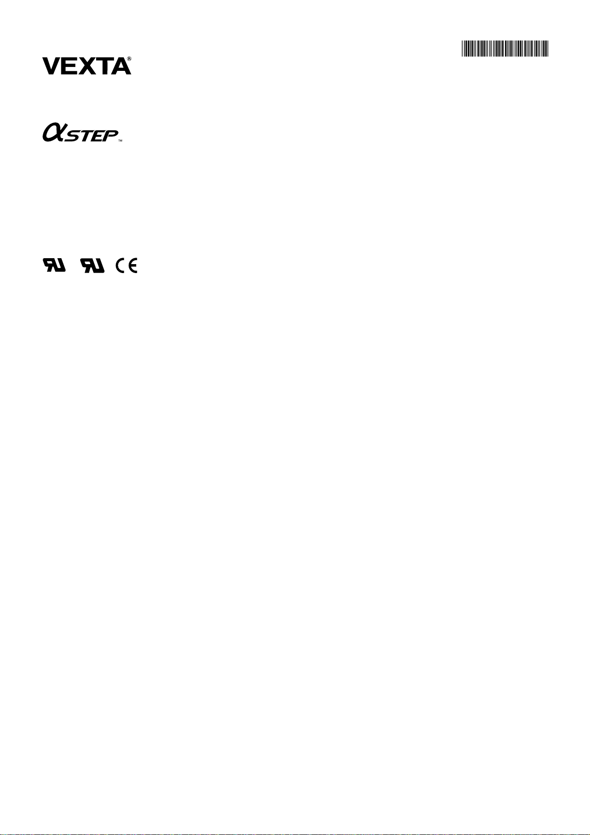
System configuration
Controllers with pulse-output functions are needed to operate the AS series.
Controller
(programmable controller
and others)
Control input
and output
Positioning controller
Pulse output and control
input/output
Shielded cable with
connectors (sold separately)
Driver
ASD24A-A
MOTOR
L
100115V
~
N
VEXTA
series
OPERATION
ALARM
CN1
Extension cable (sold separately)
500
1000
X1
X10
2P
1 2 3 4
1P
CURRENT
C
B
D
A
E
9
CN2
F
8
0
7
1
6
2
5
3
4
V.FIL
C
B
D
A
E
9
F
8
0
7
1
6
2
5
3
4
CN3
CN4
I
O
/
Motor
Control input and output
• Be sure to purchase the extension cable (for use in the model with electromagnetic brake), which is sold separately,
when using the model with the electromagnetic brake. When the motor cable is directly connected to the driver, the
electromagnetic brake will not work. Use a 24 VDC power source for the electromagnetic brake.
• The AS series is available in three input-power sources: single-phase 100-115 V, single-phase 200-230 V
and three-phase 200-230 V.
3
Page 4

Safety precautions
The precautions described below are intended to prevent danger or injury to the user and other personnel through safe,
correct use of the product. Use the product only after carefully reading and fully understanding these instructions.
Warning
Handling the product without observing the instructions that accompany a “Warning” symbol may result in serious
injury or death.
Caution
Handling the product without observing the instructions that accompany a “Caution” symbol may result in injury or
property damage.
Note
The items under this heading contain important handling instructions that the user should observe to ensure safe use
of the product.
Warning
General
• Do not use the product in explosive or corrosive environments, in the presence of flammable gases, locations
subjected to splashing water, or near combustibles. Doing so may result in fire, electric shock or injury.
• Assign qualified personnel the task of installing, wiring, operating/controlling, inspecting and troubleshooting the
product. Failure to do so may result in fire, electric shock or injury.
• Do not transport, install the product, perform connections or inspections when the power is on. Always turn the power
off before carrying out these operations. Failure to do so may result in electric shock.
• The terminals on the driver’s front panel marked with symbol indicate the presence of high voltage.
Do not touch these terminals while the power is on to avoid the risk of fire or electric shock.
• Provide a means to hold the moving parts in place for applications involving vertical travel. The motor loses holding
torque when the power is shut off, allowing the moving parts to fall and possibly cause injury or damage to
equipment.
• Do not use the motor’s built-in electromagnetic brake mechanism for stopping or for safety purposes. Using it for
purposes other than holding the moving parts and motor in position may cause injury or damage to equipment.
• When the driver-protection function is triggered, the motor will stop and lose its holding torque, possibly causing injury
or damage to equipment.
• When the driver’s protection function is triggered, first remove the cause and then clear the protection function.
Continuing the operation without removing the cause of the problem may cause malfunction of the motor, leading to
injury or damage to equipment.
Installation
• To prevent the risk of electric shock, use the motor and driver for class I equipment only.
• Install the motor and driver in their enclosures in order to prevent electric shock or injury.
• Install the motor and driver so as to avoid contact with hands, or ground them to prevent the risk of electric shock.
Connection
• Keep the driver’s input-power voltage within the specified range to avoid fire and electric shock.
• Connect the cables securely according to the wiring diagram in order to prevent fire and electric shock.
• Do not forcibly bend, pull or pinch the cable. Doing so may fire and electric shock.
• To prevent electric shock, be sure to install the terminal cover (supplied) over the driver’s power-supply terminals
after making connections.
Operation
• Turn off the driver power in the event of a power failure, or the motor may suddenly start when the power is restored
and may cause injury or damage to equipment.
• Do not turn the C.OFF (All Windings Off) input to “ON” while the motor is operating. The motor will stop and lose its
holding ability, which may result in injury or damage to equipment.
• If the driver’s OPERATION LED does not come on when the power is turned on, shut off the power immediately. The
neutral-side fuse may be burnt out while the live-side fuse is intact, posing a risk of electric shock. For repair, contact
the branch or sales office from which you purchased the product.
4
Page 5

Maintenance and inspection
• Do not touch the connection terminals of the driver immediately after the power is turned off (for a period of 10
seconds). The residual voltage may cause electric shock.
Repair , disassembly and modification
• Do not disassemble or modify the motor or driver. This may cause electric shock or injury. Refer all such internal
inspections and repairs to the branch or sales office from which you purchased the product.
Caution
General
• Do not use the motor and driver beyond their specifications, or electric shock, injury or damage to equipment may
result.
• Keep your fingers and objects out of the openings in the motor and driver, or electric shock, injury or damage to
equipment may result.
• Do not touch the motor or driver during operation or immediately after stopping. The surfaces are hot and may cause
a burn.
Transportation
• Do not hold the motor output shaft or motor cable. This may cause injury.
Installation
• Keep the area around the motor and driver free of combustible materials in order to prevent fire or a burn.
• To prevent the risk of damage to equipment, leave nothing around the motor and driver that would obstruct
ventilation.
• Provide a cover over the rotating parts (output shaft) of the motor to prevent injury.
Operation
• Use a motor and driver only in the specified combination. An incorrect combination may cause a fire.
• To avoid injury, remain alert during operation so that the motor can be stopped immediately in an emergency.
• Before supplying power to the driver, turn all control inputs to the driver to “OFF.” Otherwise, the motor may start
suddenly and cause injury or damage to equipment.
• To prevent bodily injury, do not touch the rotating parts (output shaft) of the motor during operation.
• Before moving the motor directly (as in the case of manual positioning), confirm that the driver C.OFF
(All Windings Off) input is “ON” to prevent injury.
• The motor’s surface temperature may exceed 70°C, even under normal operating conditions. If a motor is accessible
during operation, post a warning label shown in the figure in a conspicuous position to prevent the risk of burns.
Warning label
• When an abnormality is noted, stop the operation immediately, or fire, electric shock or injury may occur.
• To prevent electric shock, use only an insulated screwdriver to adjust the internal switches.
Maintenance and inspection
• To prevent the risk of electric shock, do not touch the terminals while measuring the insulation resistance or
conducting a voltage-resistance test.
Disposal
• When disposing of the motor or driver, treat them as ordinary industrial waste.
5
Page 6

Precautions for use
This section covers limitations and requirements the user should consider when using the AS series.
• Operate the motor at a level below the maximum torqu e.
Operating the motor beyond the maximum torque or placing a continuous constraint on the output shaft may damage
the motor bearings (ball bearings). Be sure to keep the motor load below the maximum torque.
• Do not apply an overhung load in excess of the specified permissible limit.
Be sure to operate the motor within the specified permissible limit of overhung load. Operating it under an excessive
overhung load may damage the motor bearings (ball bearings).
• Operate the motor with a surface temperature not exceeding 100°C (212°F).
The driver has an overheat-protection function, but the motor has no such feature. The motor case’s surface
temperature may exceed 100°C (212°F) under certain conditions (ambient temperature, operating speed, duty cycle,
etc.). Keeping the surface temperature of the motor casing below 100°C (212°F) will also maximize the life of the motor
bearings (ball bearings).
• About maximum static torque at excitation
Maximum static torque at excitation represents a value obtained when the motor is excited using a rated current. When
combined with a dedicated driver and while the motor is stopped motor-temperature increases are suppressed due to
a current-reduction of approximately 50% by the current-cutback function. Acceleration and operation at the maximum
static torque at excitation is possible in start-up, but it has approximately 50% holding power after it has stopped. When
selecting a motor for your application, consider the fact that the holding power will be reduced to approximately 50%
after the motor has stopped.
• Use an electromagnetic-brake type for an application involving up/down travel.
When the motor is used in an application involving up/down travel, such as a lifter, use an electromagnetic-brake type
to hold the load in position. To hold the load in position, apply the electromagnetic brake only after the motor has
stopped.
Do not use the brake to bring the moving motor to a halt. Repeated braking for such a purpose will wear the brake hub
excessively, causing its holding ability to drop.
Since the electromagnetic brake is of the non-excitation type, it can also be used to hold the load in position upon the
occurrence of a power failure. However, this is not a secure means of holding the load.
Do not use the electromagnetic brake as a safety brake.
When the driver-protection function is triggered, the motor stops as the current is turned off. The user must set a
controller sequence that will cut off the power to the electromagnetic brake and hold the load in position upon detecting
an “OFF” ALARM output.
• Connecting an electromagnetic-brake type
Be sure to use a junction cable (sold separately) for connection of an electromagnetic-brake type and driver. Direct
connection of the motor cable to the driver will not provide the electromagnetic brake function.
The electromagnetic brake operates via the ON/OFF status of the DC power supply. When connecting the lead wires
of the electromagnetic brake extending from the junction cable, observe the correct polarity. Be sure to connect the
supplied varistor (non-polarized) to protect the switch contacts and prevent noise.
• Install the driver in a vertical orientation.
The driver’s heat-dissipation function is designed according to vertical orientation. Installing the driver in any other
orientation may shorten the life of electronic parts due to temperature increases within the driver.
• Preventing leakage current
Stray capacitance exists between the driver’s current-carrying line and other current-carrying lines, the earth and the
motor, respectively. A high-frequency current may leak out through such capacitance, having a detrimental effect on the
surrounding equipment. The actual leakage current depends on the driver’s switching frequency, the length of wiring
between the driver and motor, and so on.
When providing a leakage current breaker, use the following products, for instance, which have high-frequency signal
protection:
Mitsubishi Electric: NV series
Fuji Electric: EG and SG series
6
Page 7

• Preventing electrical noise
See “Installing and wiring in compliance with EMC directive” on page 22 for measures with regard to noise.
7
Page 8
Preparation
This section covers the points to be checked along with the names and functions of respective parts.
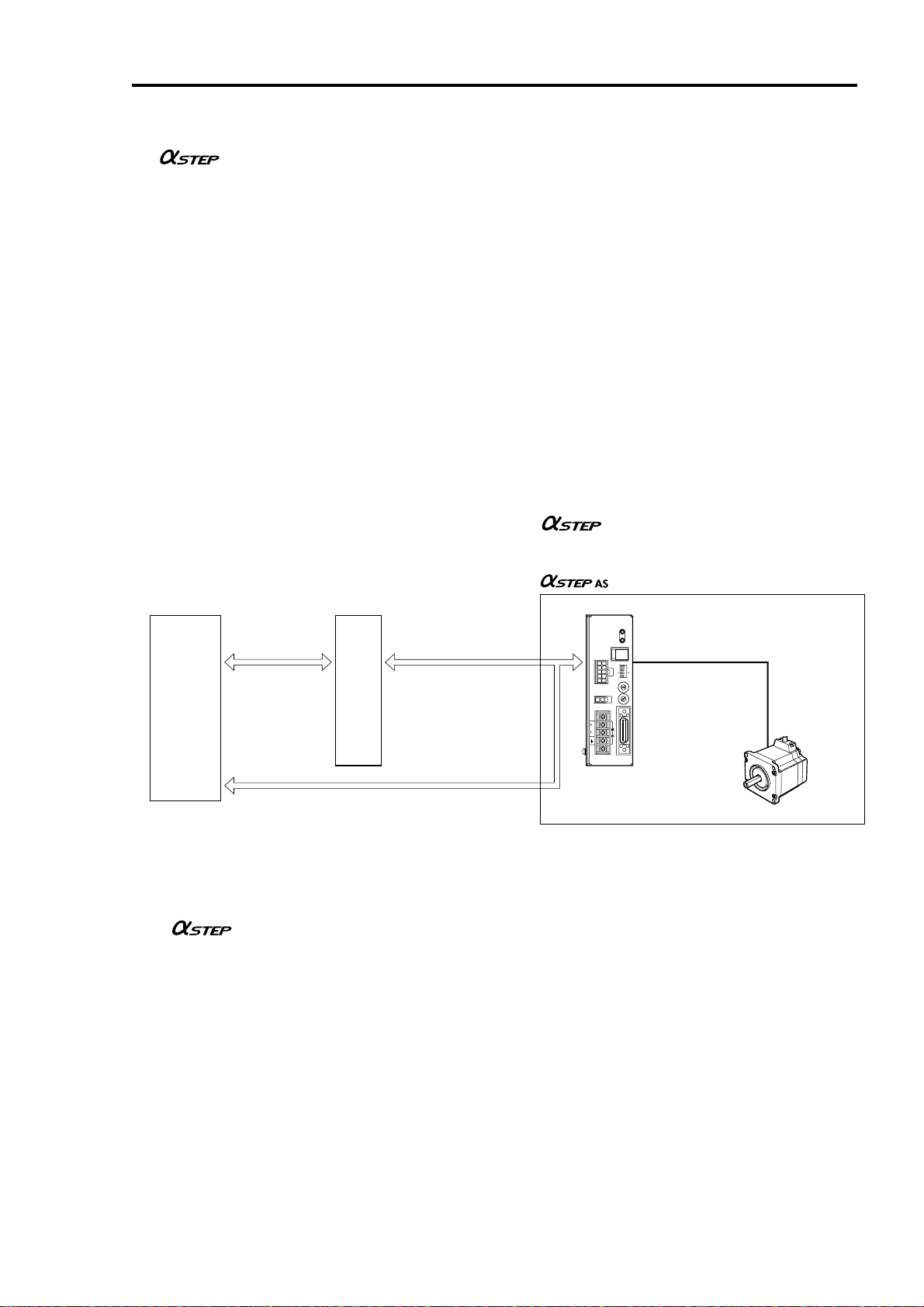
Checking the product
Upon opening the package, verify that the items listed below are included.
Report any missing or damaged items to the branch or sales office from which you purchased the product.
Verify the model number of the purchased unit against the number shown on the package label.
Check the model number of the motor and driver against the number shown on the nameplate.
The unit models and corresponding motor/driver combinations are listed on pages 10 to 13.
ASD24A-A
N
IO
T
A
R
E
P
O
∗
Illustration shows the round
shaft type with
electromagnetic brake.
∗ A parallel key (1 unit) is supplied
with all geared-type motors
(excluding the AS66 TH geared
type).
ALARM
1
N
C
1000
F/H
NORM
1P
C
B
A
9
8
7
CN2
R
C
O
T
B
O
M
A
9
8
7
3
N
C
L
00-
1
~
V
5
11
N
C
I/O
VEXTA
Driver mounting brackets
2 pieces
500
4
3
X10
2
TEST
1
N
O
2P
E
D
F
0
1
2
3
4
5
6
E
D
F
0
1
2
3
4
5
6
Control input/output connector
4
N
1 set
3
‑
A
5
8F
‑
C
5
Driver 1 UnitMotor 1 Unit
Varistor 1 piece
Varistor supplied with the motor with
an electromagnetic-brake type
Screws for driver mounting
brackets (M3) 4 pieces
Operating manual
1 copy
8
Page 9
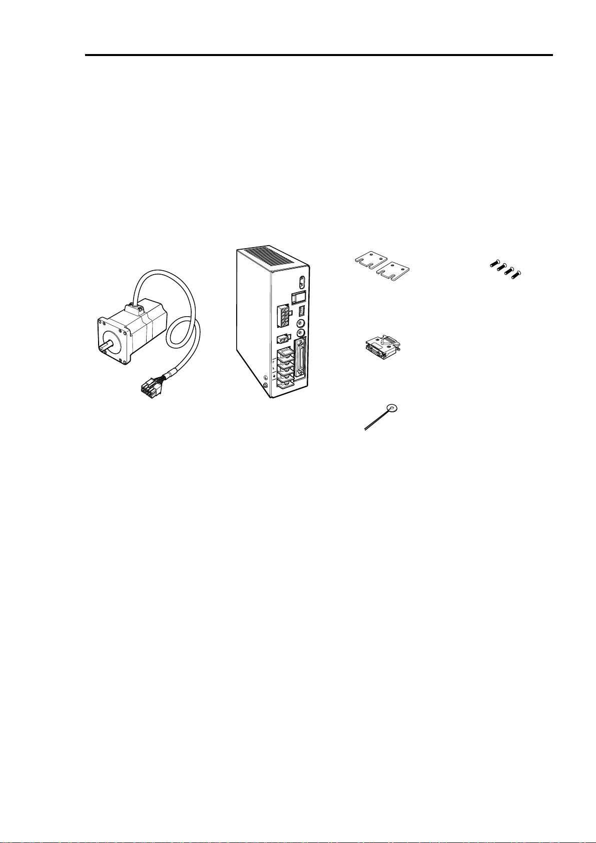
How to identify the product model
Geared type
A S 6 6 A A 2 - H 50
Motor type
A: Standard type
M: With electromagnetic brake
Motor length
Motor size
6: 60 mm (2.36 in.) square
9: 90 mm (3.54 in.) square
Series name AS series
Gear ratio
Gear type
T: TH gear
P: PL gear
N: PN gear
H: Harmonic gear
Power input
A: Single-phase 100-115 V
C: Single-phase 200-230 V
S: Three-phase 200-230 V
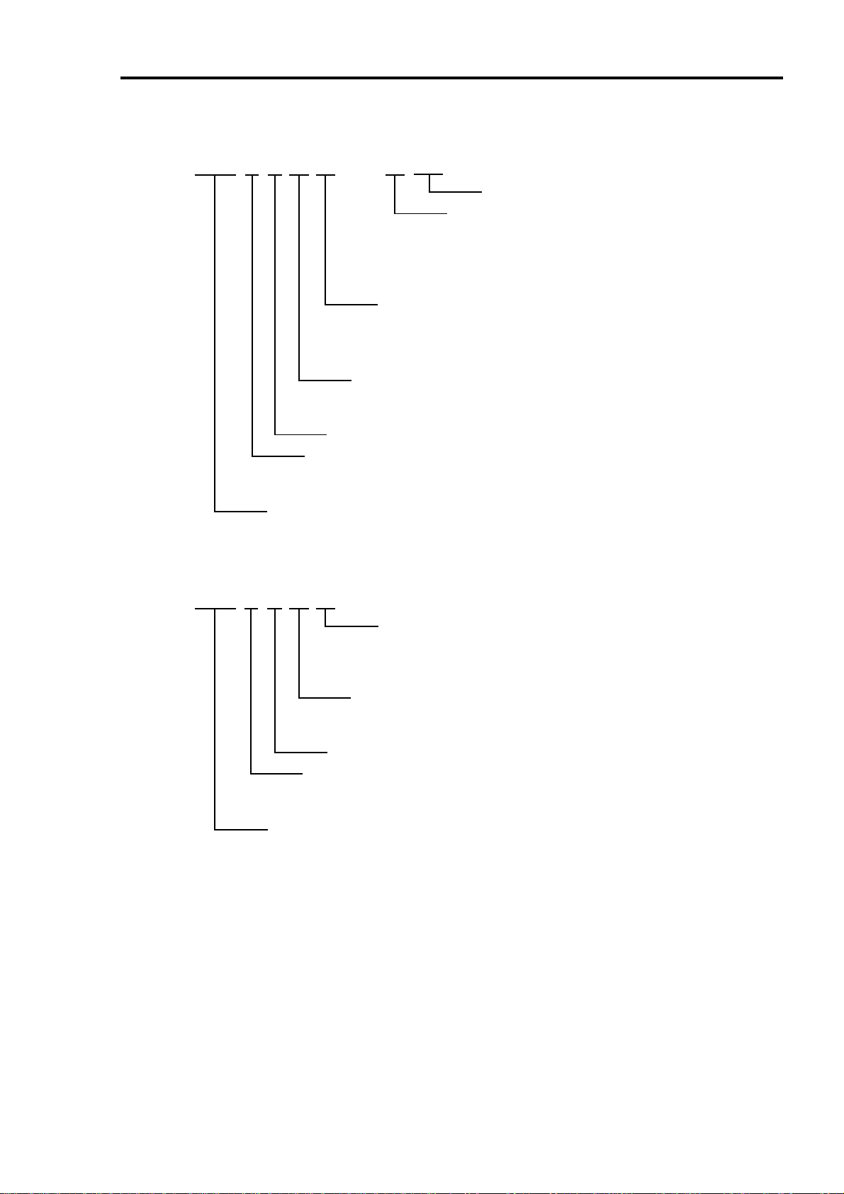
Round shaft type
A S 6 6 A A
Power input
A: Single-phase 100-115 V
C: Single-phase 200-230 V
S: Three-phase 200-230 V
Motor type
A: Standard type
M: With electromagnetic brake
Motor length
Motor size
6: 60 mm (2.36 in.) square
9: 85 mm (3.35 in.) square
Series name AS series
Options (sold separately)
• Extension cable Pages 31, 32 and 61
Required for extending the distance between the motor and driver.
Be sure to use the electromagnetic-brake extension cable to connect an electromagnetic-brake-type motor.
• Flexible cable Pages 32 and 61
Highly flexible extension cable.
• Shielded cable with connectors Pages 33 and 61
Cable with connectors for driver control input/output (36 pins), providing excellent noise resistance.
• DIN rail mounting plate Pages 21 and 61
Plate for mounting the driver to a DIN rail.
9
Page 10

Combinations of motors and drivers
TH geared type
Standard type
Unit model
AS66AA-T3.6
AS66AA-T7.2
AS66AA-T10
AS66AA-T20
AS66AA-T30
AS66AC-T3.6
AS66AC-T7.2
AS66AC-T10
AS66AC-T20
AS66AC-T30
AS66AS-T3.6
AS66AS-T7.2
AS66AS-T10
AS66AS-T20
AS66AS-T30
AS98AA-T3.6
AS98AA-T7.2
AS98AA-T10
AS98AA-T20
AS98AA-T30
AS98AC-T3.6
AS98AC-T7.2
AS98AC-T10
AS98AC-T20
AS98AC-T30
AS98AS-T3.6
AS98AS-T7.2
AS98AS-T10
AS98AS-T20
AS98AS-T30
Motor model
ASM66AA-T3.6
ASM66AA-T7.2
ASM66AA-T10
ASM66AA-T20
ASM66AA-T30
ASM66AC-T3.6
ASM66AC-T7.2
ASM66AC-T10
ASM66AC-T20
ASM66AC-T30
ASM66AC-T3.6
ASM66AC-T7.2
ASM66AC-T10
ASM66AC-T20
ASM66AC-T30
ASM98AA-T3.6
ASM98AA-T7.2
ASM98AA-T10
ASM98AA-T20
ASM98AA-T30
ASM98AC-T3.6
ASM98AC-T7.2
ASM98AC-T10
ASM98AC-T20
ASM98AC-T30
ASM98AC-T3.6
ASM98AC-T7.2
ASM98AC-T10
ASM98AC-T20
ASM98AC-T30
Driver model
ASD24B-A
ASD24B-A
ASD24B-A
ASD24C-A
ASD24C-A
ASD12B-C
ASD12B-C
ASD12B-C
ASD12C-C
ASD12C-C
ASD12B-S
ASD12B-S
ASD12B-S
ASD12C-S
ASD12C-S
ASD30A-A
ASD30A-A
ASD30A-A
ASD30C-A
ASD30C-A
ASD16A-C
ASD16A-C
ASD16A-C
ASD16C-C
ASD16C-C
ASD16A-S
ASD16A-S
ASD16A-S
ASD16C-S
ASD16C-S
Electromagnetic-brake type
Unit model
AS66MA-T3.6
AS66MA-T7.2
AS66MA-T10
AS66MA-T20
AS66MA-T30
AS66MC-T3.6
AS66MC-T7.2
AS66MC-T10
AS66MC-T20
AS66MC-T30
AS66MS-T3.6
AS66MS-T7.2
AS66MS-T10
AS66MS-T20
AS66MS-T30
AS98MA-T3.6
AS98MA-T7.2
AS98MA-T10
AS98MA-T20
AS98MA-T30
AS98MC-T3.6
AS98MC-T7.2
AS98MC-T10
AS98MC-T20
AS98MC-T30
AS98MS-T3.6
AS98MS-T7.2
AS98MS-T10
AS98MS-T20
AS98MS-T30
Motor model
ASM66MA-T3.6
ASM66MA-T7.2
ASM66MA-T10
ASM66MA-T20
ASM66MA-T30
ASM66MC-T3.6
ASM66MC-T7.2
ASM66MC-T10
ASM66MC-T20
ASM66MC-T30
ASM66MC-T3.6
ASM66MC-T7.2
ASM66MC-T10
ASM66MC-T20
ASM66MC-T30
ASM98MA-T3.6
ASM98MA-T7.2
ASM98MA-T10
ASM98MA-T20
ASM98MA-T30
ASM98MC-T3.6
ASM98MC-T7.2
ASM98MC-T10
ASM98MC-T20
ASM98MC-T30
ASM98MC-T3.6
ASM98MC-T7.2
ASM98MC-T10
ASM98MC-T20
ASM98MC-T30
Driver model
ASD24B-A
ASD24B-A
ASD24B-A
ASD24C-A
ASD24C-A
ASD12B-C
ASD12B-C
ASD12B-C
ASD12C-C
ASD12C-C
ASD12B-S
ASD12B-S
ASD12B-S
ASD12C-S
ASD12C-S
ASD30A-A
ASD30A-A
ASD30A-A
ASD30C-A
ASD30C-A
ASD16A-C
ASD16A-C
ASD16A-C
ASD16C-C
ASD16C-C
ASD16A-S
ASD16A-S
ASD16A-S
ASD16C-S
ASD16C-S
10
Page 11

PL geared type
Unit model
AS66AA-P5
AS66AA-P7.2
AS66AA-P10
AS66AA-P25
AS66AA-P36
AS66AA-P50
AS66AC-P5
AS66AC-P7.2
AS66AC-P10
AS66AC-P25
AS66AC-P36
AS66AC-P50
AS66AS-P5
AS66AS-P7.2
AS66AS-P10
AS66AS-P25
AS66AS-P36
AS66AS-P50
AS98AA-P5
AS98AA-P7.2
AS98AA-P10
AS98AA-P25
AS98AA-P36
AS98AA-P50
AS98AC-P5
AS98AC-P7.2
AS98AC-P10
AS98AC-P25
AS98AC-P36
AS98AC-P50
AS98AS-P5
AS98AS-P7.2
AS98AS-P10
AS98AS-P25
AS98AS-P36
AS98AS-P50
Standard type
Motor model
ASM66AA-P5
ASM66AA-P7.2
ASM66AA-P10
ASM66AA-P25
ASM66AA-P36
ASM66AA-P50
ASM66AC-P5
ASM66AC-P7.2
ASM66AC-P10
ASM66AC-P25
ASM66AC-P36
ASM66AC-P50
ASM66AC-P5
ASM66AC-P7.2
ASM66AC-P10
ASM66AC-P25
ASM66AC-P36
ASM66AC-P50
ASM98AA-P5
ASM98AA-P7.2
ASM98AA-P10
ASM98AA-P25
ASM98AA-P36
ASM98AA-P50
ASM98AC-P5
ASM98AC-P7.2
ASM98AC-P10
ASM98AC-P25
ASM98AC-P36
ASM98AC-P50
ASM98AC-P5
ASM98AC-P7.2
ASM98AC-P10
ASM98AC-P25
ASM98AC-P36
ASM98AC-P50
Driver model
ASD24A-A
ASD24A-A
ASD24A-A
ASD24B-A
ASD24C-A
ASD24C-A
ASD12A-C
ASD12A-C
ASD12A-C
ASD12B-C
ASD12C-C
ASD12C-C
ASD12A-S
ASD12A-S
ASD12A-S
ASD12B-S
ASD12C-S
ASD12C-S
ASD30A-A
ASD30A-A
ASD30A-A
ASD30A-A
ASD30B-A
ASD30B-A
ASD16A-C
ASD16A-C
ASD16A-C
ASD16A-C
ASD16B-C
ASD16B-C
ASD16A-S
ASD16A-S
ASD16A-S
ASD16A-S
ASD16B-S
ASD16B-S
Electromagnetic-brake type
Unit model
AS66MA-P5
AS66MA-P7.2
AS66MA-P10
AS66MA-P25
AS66MA-P36
AS66MA-P50
AS66MC-P5
AS66MC-P7.2
AS66MC-P10
AS66MC-P25
AS66MC-P36
AS66MC-P50
AS66MS-P5
AS66MS-P7.2
AS66MS-P10
AS66MS-P25
AS66MS-P36
AS66MS-P50
AS98MA-P5
AS98MA-P7.2
AS98MA-P10
AS98MA-P25
AS98MA-P36
AS98MA-P50
AS98MC-P5
AS98MC-P7.2
AS98MC-P10
AS98MC-P25
AS98MC-P36
AS98MC-P50
AS98MS-P5
AS98MS-P7.2
AS98MS-P10
AS98MS-P25
AS98MS-P36
AS98MS-P50
Motor model
ASM66MA-P5
ASM66MA-P7.2
ASM66MA-P10
ASM66MA-P25
ASM66MA-P36
ASM66MA-P50
ASM66MC-P5
ASM66MC-P7.2
ASM66MC-P10
ASM66MC-P25
ASM66MC-P36
ASM66MC-P50
ASM66MC-P5
ASM66MC-P7.2
ASM66MC-P10
ASM66MC-P25
ASM66MC-P36
ASM66MC-P50
ASM98MA-P5
ASM98MA-P7.2
ASM98MA-P10
ASM98MA-P25
ASM98MA-P36
ASM98MA-P50
ASM98MC-P5
ASM98MC-P7.2
ASM98MC-P10
ASM98MC-P25
ASM98MC-P36
ASM98MC-P50
ASM98MC-P5
ASM98MC-P7.2
ASM98MC-P10
ASM98MC-P25
ASM98MC-P36
ASM98MC-P50
Driver model
ASD24A-A
ASD24A-A
ASD24A-A
ASD24B-A
ASD24C-A
ASD24C-A
ASD12A-C
ASD12A-C
ASD12A-C
ASD12B-C
ASD12C-C
ASD12C-C
ASD12A-S
ASD12A-S
ASD12A-S
ASD12B-S
ASD12C-S
ASD12C-S
ASD30A-A
ASD30A-A
ASD30A-A
ASD30A-A
ASD30B-A
ASD30B-A
ASD16A-C
ASD16A-C
ASD16A-C
ASD16A-C
ASD16B-C
ASD16B-C
ASD16A-S
ASD16A-S
ASD16A-S
ASD16A-S
ASD16B-S
ASD16B-S
11
Page 12

PN geared type
Unit model
AS66AA-N5
AS66AA-N7.2
AS66AA-N10
AS66AA-N25
AS66AA-N36
AS66AA-N50
AS66AC-N5
AS66AC-N7.2
AS66AC-N10
AS66AC-N25
AS66AC-N36
AS66AC-N50
AS66AS-N5
AS66AS-N7.2
AS66AS-N10
AS66AS-N25
AS66AS-N36
AS66AS-N50
AS98AA-N5
AS98AA-N7.2
AS98AA-N10
AS98AA-N25
AS98AA-N36
AS98AA-N50
AS98AC-N5
AS98AC-N7.2
AS98AC-N10
AS98AC-N25
AS98AC-N36
AS98AC-N50
AS98AS-N5
AS98AS-N7.2
AS98AS-N10
AS98AS-N25
AS98AS-N36
AS98AS-N50
Standard type
Motor model
ASM66AA-N5
ASM66AA-N7.2
ASM66AA-N10
ASM66AA-N25
ASM66AA-N36
ASM66AA-N50
ASM66AC-N5
ASM66AC-N7.2
ASM66AC-N10
ASM66AC-N25
ASM66AC-N36
ASM66AC-N50
ASM66AC-N5
ASM66AC-N7.2
ASM66AC-N10
ASM66AC-N25
ASM66AC-N36
ASM66AC-N50
ASM98AA-N5
ASM98AA-N7.2
ASM98AA-N10
ASM98AA-N25
ASM98AA-N36
ASM98AA-N50
ASM98AC-N5
ASM98AC-N7.2
ASM98AC-N10
ASM98AC-N25
ASM98AC-N36
ASM98AC-N50
ASM98AC-N5
ASM98AC-N7.2
ASM98AC-N10
ASM98AC-N25
ASM98AC-N36
ASM98AC-N50
Driver model
ASD24A-A
ASD24A-A
ASD24A-A
ASD24B-A
ASD24C-A
ASD24C-A
ASD12A-C
ASD12A-C
ASD12A-C
ASD12B-C
ASD12C-C
ASD12C-C
ASD12A-S
ASD12A-S
ASD12A-S
ASD12B-S
ASD12C-S
ASD12C-S
ASD30A-A
ASD30A-A
ASD30A-A
ASD30A-A
ASD30B-A
ASD30B-A
ASD16A-C
ASD16A-C
ASD16A-C
ASD16A-C
ASD16B-C
ASD16B-C
ASD16A-S
ASD16A-S
ASD16A-S
ASD16A-S
ASD16B-S
ASD16B-S
Electromagnetic-brake type
Unit model
AS66MA-N5
AS66MA-N7.2
AS66MA-N10
AS66MA-N25
AS66MA-N36
AS66MA-N50
AS66MC-N5
AS66MC-N7.2
AS66MC-N10
AS66MC-N25
AS66MC-N36
AS66MC-N50
AS66MS-N5
AS66MS-N7.2
AS66MS-N10
AS66MS-N25
AS66MS-N36
AS66MS-N50
AS98MA-N5
AS98MA-N7.2
AS98MA-N10
AS98MA-N25
AS98MA-N36
AS98MA-N50
AS98MC-N5
AS98MC-N7.2
AS98MC-N10
AS98MC-N25
AS98MC-N36
AS98MC-N50
AS98MS-N5
AS98MS-N7.2
AS98MS-N10
AS98MS-N25
AS98MS-N36
AS98MS-N50
Motor model
ASM66MA-N5
ASM66MA-N7.2
ASM66MA-N10
ASM66MA-N25
ASM66MA-N36
ASM66MA-N50
ASM66MC-N5
ASM66MC-N7.2
ASM66MC-N10
ASM66MC-N25
ASM66MC-N36
ASM66MC-N50
ASM66MC-N5
ASM66MC-N7.2
ASM66MC-N10
ASM66MC-N25
ASM66MC-N36
ASM66MC-N50
ASM98MA-N5
ASM98MA-N7.2
ASM98MA-N10
ASM98MA-N25
ASM98MA-N36
ASM98MA-N50
ASM98MC-N5
ASM98MC-N7.2
ASM98MC-N10
ASM98MC-N25
ASM98MC-N36
ASM98MC-N50
ASM98MC-N5
ASM98MC-N7.2
ASM98MC-N10
ASM98MC-N25
ASM98MC-N36
ASM98MC-N50
Driver model
ASD24A-A
ASD24A-A
ASD24A-A
ASD24B-A
ASD24C-A
ASD24C-A
ASD12A-C
ASD12A-C
ASD12A-C
ASD12B-C
ASD12C-C
ASD12C-C
ASD12A-S
ASD12A-S
ASD12A-S
ASD12B-S
ASD12C-S
ASD12C-S
ASD30A-A
ASD30A-A
ASD30A-A
ASD30A-A
ASD30B-A
ASD30B-A
ASD16A-C
ASD16A-C
ASD16A-C
ASD16A-C
ASD16B-C
ASD16B-C
ASD16A-S
ASD16A-S
ASD16A-S
ASD16A-S
ASD16B-S
ASD16B-S
12
Page 13
Harmonic geared type
Standard type
Unit model
AS66AA2-H50
AS66AA2-H100
AS66AC2-H50
AS66AC2-H100
AS66AS2-H50
AS66AS2-H100
AS66AA-H50
AS66AA-H100
AS66AC-H50
AS66AC-H100
AS66AS-H50
AS66AS-H100
AS98AA-H50
AS98AA-H100
AS98AC-H50
AS98AC-H100
AS98AS-H50
AS98AS-H100
Motor model
ASM66AA2-H50
ASM66AA2-H100
ASM66AC2-H50
ASM66AC2-H100
ASM66AC2-H50
ASM66AC2-H100
ASM66AA-H50
ASM66AA-H100
ASM66AC-H50
ASM66AC-H100
ASM66AC-H50
ASM66AC-H100
ASM98AA-H50
ASM98AA-H100
ASM98AC-H50
ASM98AC-H100
ASM98AC-H50
ASM98AC-H100
Round shaft type
Standard type
Unit model
AS66AA
AS69AA
AS66AC
AS69AC
AS66AS
AS69AS
AS98AA
AS911AA
AS98AC
AS911AC
AS98AS
AS911AS
Motor model
ASM66AA
ASM69AA
ASM66AC
ASM69AC
ASM66AC
ASM69AC
ASM98AA
ASM911AA
ASM98AC
ASM911AC
ASM98AC
ASM911AC
Driver model
ASD24B-A
ASD24C-A
ASD12B-C
ASD12C-C
ASD12B-S
ASD12C-S
ASD24C-A
ASD24C-A
ASD12C-C
ASD12C-C
ASD12C-S
ASD12C-S
ASD30B-A
ASD30B-A
ASD16B-C
ASD16B-C
ASD16B-S
ASD16B-S
Driver model
ASD24A-A
ASD30D-A
ASD12A-C
ASD16D-C
ASD12A-S
ASD16D-S
ASD30A-A
ASD30E-A
ASD16A-C
ASD20A-C
ASD16A-S
ASD20A-S
Electromagnetic-brake type
Unit model
AS66MA2-H50
AS66MA2-H100
AS66MC2-H50
AS66MC2-H100
AS66MS2-H50
AS66MS2-H100
AS66MA-H50
AS66MA-H100
AS66MC-H50
AS66MC-H100
AS66MS-H50
AS66MS-H100
AS98MA-H50
AS98MA-H100
AS98MC-H50
AS98MC-H100
AS98MS-H50
AS98MS-H100
Electromagnetic-brake type
Unit model
AS66MA
AS69MA
AS66MC
AS69MC
AS66MS
AS69MS
AS98MA
AS98MC
AS98MS
Motor model
ASM66MA2-H50
ASM66MA2-H100
ASM66MC2-H50
ASM66MC2-H100
ASM66MC2-H50
ASM66MC2-H100
ASM66MA-H50
ASM66MA-H100
ASM66MC-H50
ASM66MC-H100
ASM66MC-H50
ASM66MC-H100
ASM98MA-H50
ASM98MA-H100
ASM98MC-H50
ASM98MC-H100
ASM98MC-H50
ASM98MC-H100
Motor model
ASM66MA
ASM69MA
ASM66MC
ASM69MC
ASM66MC
ASM69MC
ASM98MA
ASM98MC
ASM98MC
Driver model
ASD24B-A
ASD24C-A
ASD12B-C
ASD12C-C
ASD12B-S
ASD12C-S
ASD24C-A
ASD24C-A
ASD12C-C
ASD12C-C
ASD12C-S
ASD12C-S
ASD30B-A
ASD30B-A
ASD16B-C
ASD16B-C
ASD16B-S
ASD16B-S
Driver model
ASD24A-A
ASD30D-A
ASD12A-C
ASD16D-C
ASD12A-S
ASD16D-S
ASD30A-A
ASD16A-C
ASD16A-S
13
Page 14
Names and functions of parts
This section covers the names and functions of parts in the motor and driver.
For further details on each part, refer to the page shown in the square bracket.
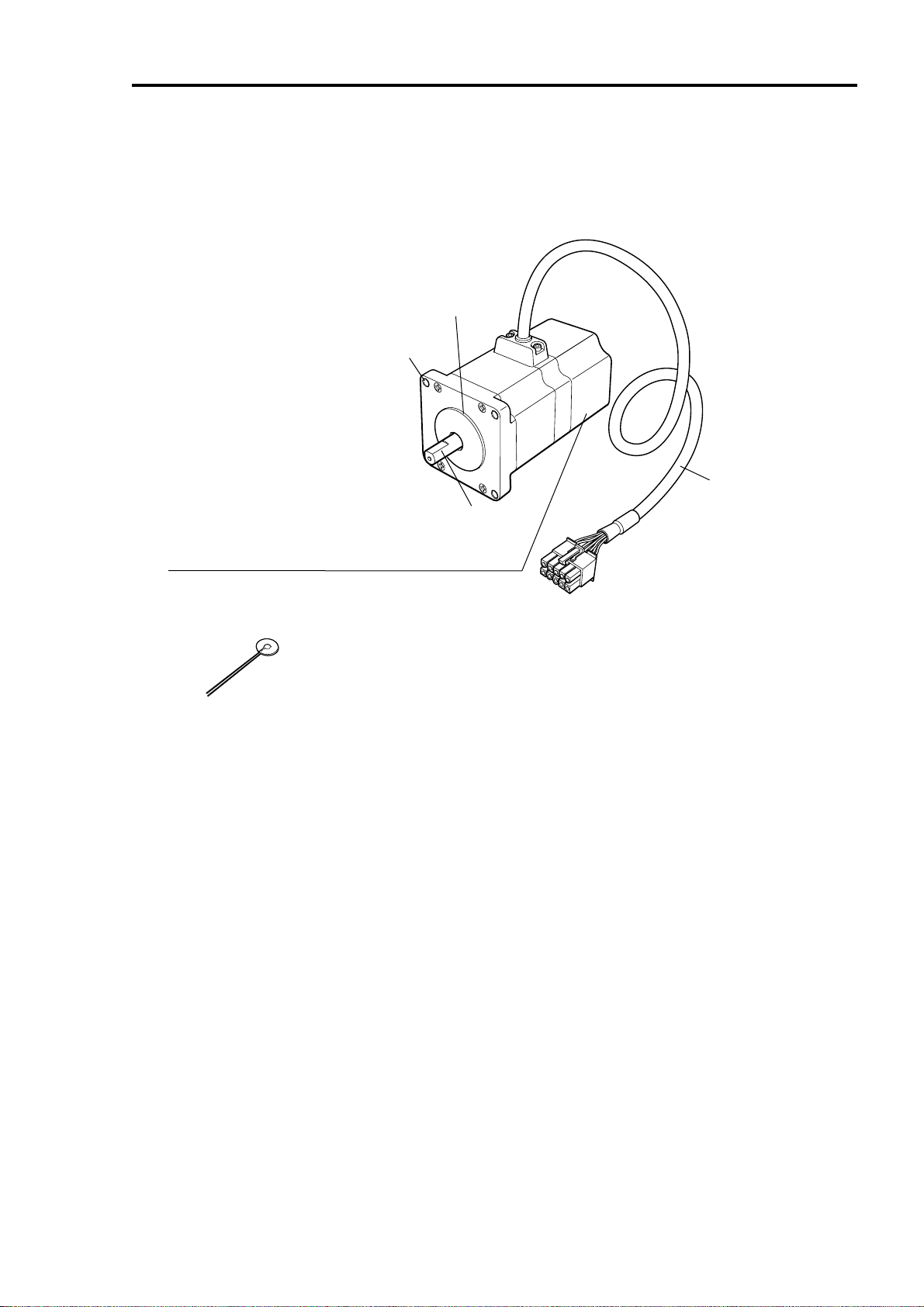
Motor
Mounting holes (four locations) [P.16]
Electromagnetic brake [motor with an electromagnetic brake] [P.32,41]
Non-excitation operation electromagnetic brake (24 VDC input)
Varistor
3
‑
A
5
8F
‑
C
5
Pilot
Motor cable [P.31,32]
Output shaft
An accessory supplied with the motor with an electromagnetic brake.
Be sure to connect the varistor when wiring the electromagnetic brake.
14
Page 15
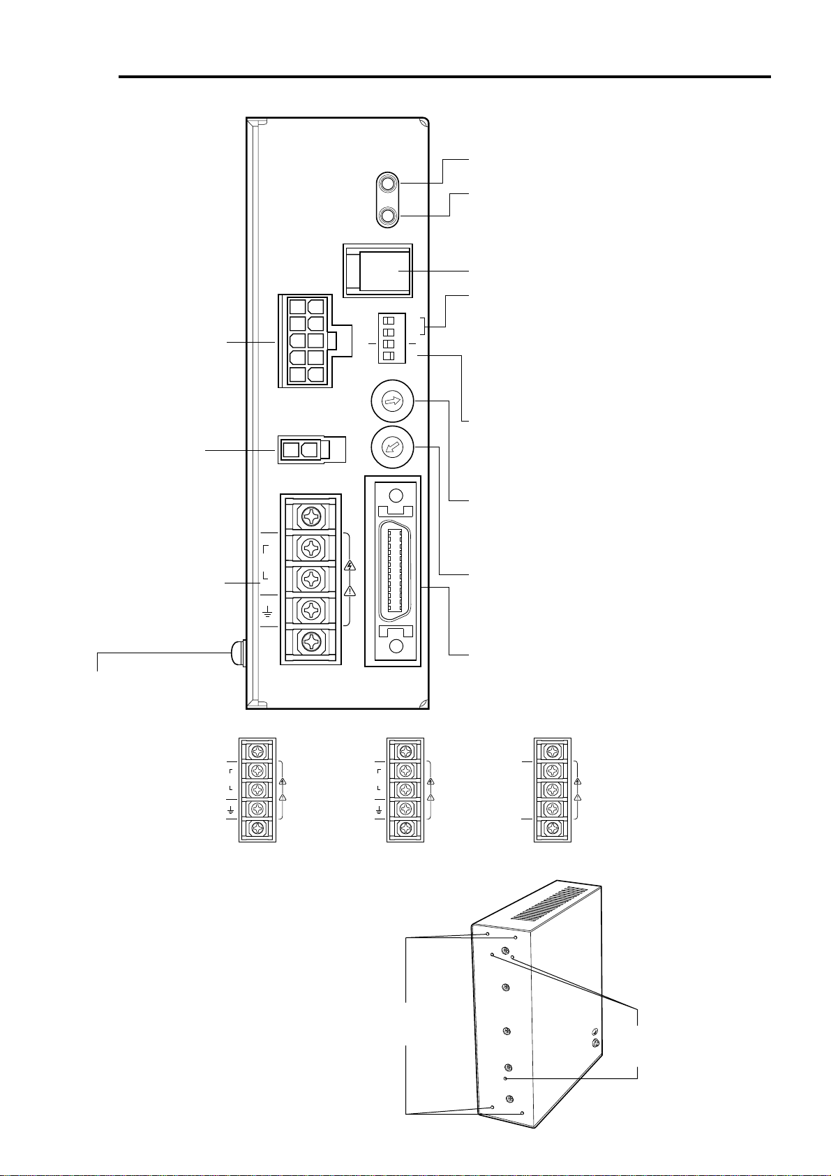
Driver
Motor connector (CN2)
[P.31,32]
Connect the motor cable's
connector.
Regeneration unit
connector (CN3)
Power supply terminal
[P.28,29,30]
Connect the power-supply
cable.
Front side of driver
ASD24A-A
OPERATION
CN1
CN2
MOTOR
CN3
L
100115V
~
N
ALARM
1000
CURRENT
V.FIL
OPERATION (green)
Lit when the power is on.
ALARM (Red) [P.46]
This alarm blinks when a protective function is triggered and
the ALARM output turns "OFF."
Count the number of blinks to ascertain the cause of triggering
of the protective function.
Not used (CN1)
Resolution selection switches [P.43]
500
X1
X10
2P
1 2 3 4
1P
Use these two switches to select the motor resolution.
1000/500: Switches motor resolution between 1000 P/R
"0.36˚/pulse" or 500 P/R "0.72˚ //pulse."
×1/ ×10: Switches motor resolution between multipliers 1 and
10 of the value set by the 1000/500 switch.
The factory setting is "1000: 1000 P/R" and "×1: Multiplier 1."
C
D
B
E
A
F
9
8
0
7
1
6
2
5
3
4
C
D
B
E
A
F
9
8
0
7
1
6
2
5
3
4
Be sure to switch to "×1" when the resolution switching input
"CN4 Pin No. 31, 32: ×10" is used.
Pulse-input mode selection switch [P.44]
Allows for the selection of 2-pulse input mode or 1-pulse input
mode in accordance with the pulse-output mode in the
positioning controller.
The factory setting is "2P: 2-Pulse Input Mode."
Current setting switch [P.44]
Sets the motor's operating current.
If there is extra torque, the current may be set to a lower level
in order to suppress increases in motor temperature.
The factory setting is "F: Driver's maximum output-current value."
Speed-filter selection switch [P.45]
Sets the time constant for the filter that determines motor response.
A longer time constant will smooth out the motor's rotation but
render the setting time longer at motor standstill.
The factory setting is "6: 1.20 ms."
Protective earth terminal [P.33]
Used for grounding via a
grounding cable of AWG18
(0.75 mm
2
) or more.
•
Driver power-supply terminal
Single-phase 100-115 V
Control input/output connectors (CN4) [P.25,26,27,33,34,35]
CN4
I
O
/
Used to connect to the motor-positioning control and others.
VEXTA
L
100115V
~
N
Mounting holes for the driver
mounting brackets
(M3, four locations) [P.19]
L
200230V
~
N
•
Driver power-supply terminal
Single-phase 200-230 V
Rear side of driver
L1
L2
L3
•
Driver power-supply terminal
Three-phase 200-230 V
Mounting holes for the DIN rail
mounting plate
(M3, three locations) [P.21]
15
Page 16
Installation
This section covers the environment and method of installing the motor and driver, along with
load installation.
Also covered in this section are the installation and wiring methods that are in compliance with
the relevant EMC directives (89/336/EEC, 92/31/EEC).
Location for installation
The motor and driver are designed and manufactured for installation in equipment.
Install them in a well-ventilated location that provides easy access for inspection. The location
must also satisfy the following conditions:
• Inside an enclosure that is installed indoors (provide vent holes)
• Operating ambient temperature Motor: 0°C to +50°C (+32°F to +122°F) (non-freezing)
Harmonic geared type: 0°C to +40°C (+32°F to +104°F)
(non-freezing)
Driver: 0°C to +50°C (+32°F to +122°F) (non-freezing)
• Operating ambient humidity 85%, maximum (no condensation)
• Area that is free from an explosive nature or toxic gas (such as sulfuric gas) or liquid
• Area not exposed to direct sun
• Area free of excessive amount dust, iron particles or the like
• Area not subject to splashing water (storms, water droplets), oil (oil droplets) or other liquids
• Area free of excessive salt
• Area not subject to continuous vibration or excessive shocks
• Area free of excessive electromagnetic noise (from welders, power machinery, etc.)
• Area free of radioactive materials, magnetic fields or vacuum
• 1000 m or lower above sea level
Note
Insert the pilot located on the
motor’s installation surface into
the mounting plate’s countersunk
or through hole.
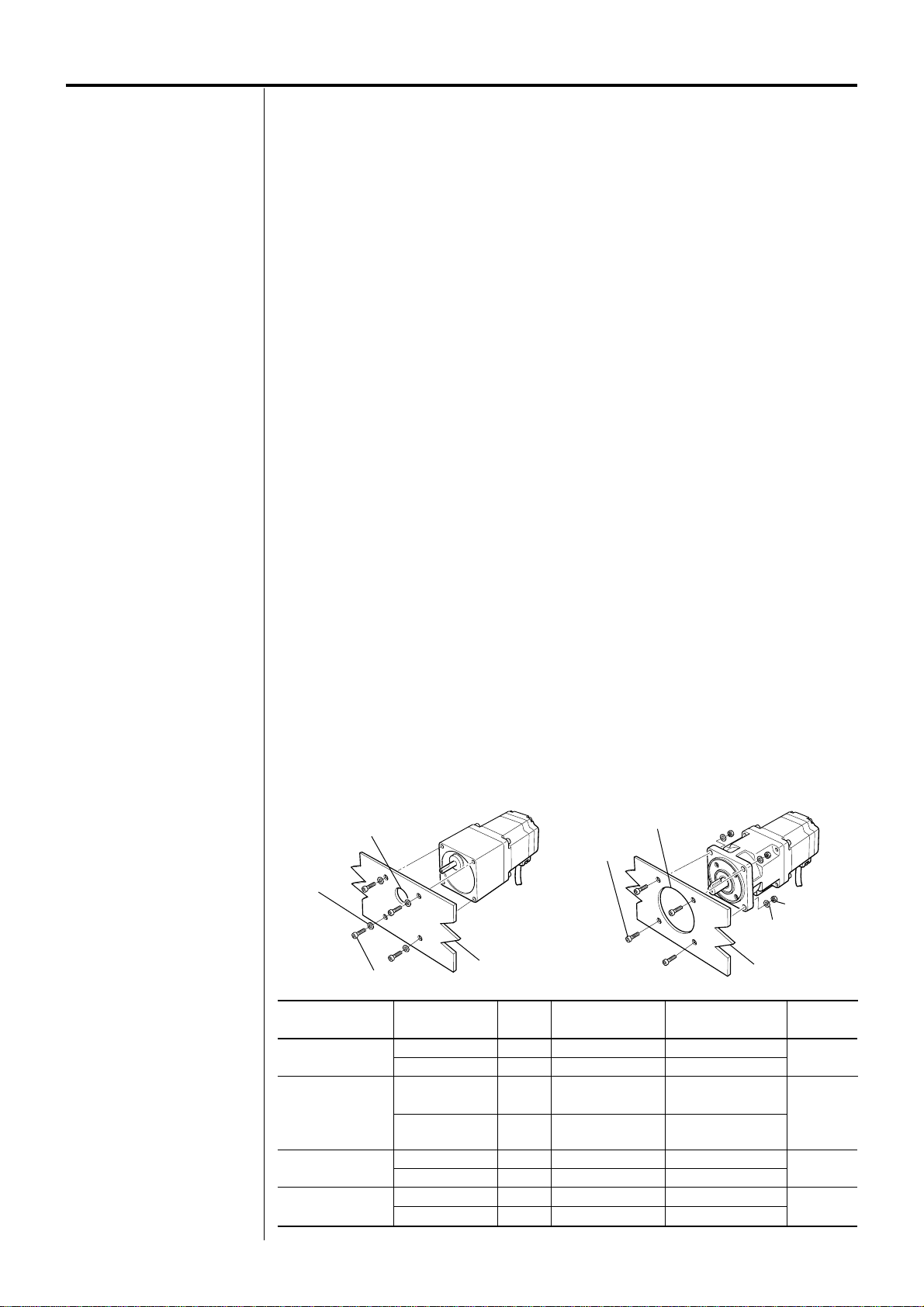
Installing the motor
How to install the motor
Install the motor onto an appropriate flat metal plate having excellent vibration resistance and
heat conductivity.
When installing the motor, secure it with four bolts (not supplied) through the four mounting
holes provided. Leave no gap between the motor and plate.
• Types of installation
A B
Spot facing or through hole for pilot
Spring washer
Hexagonal socket screw
Motor type
TH geared
PL geared
PN geared
Harmonic geared
AS66A2, AS66M2
Harmonic geared
AS66A, AS98A
Round shaft
Frame size
60 mm (2.36 in.)
90 mm (3.54 in.)
60 mm (2.36 in.)
90 mm (3.54 in.)
60 mm (2.36 in.)
90 mm (3.54 in.)
60 mm (2.36 in.)
85 mm (3.35 in.)
Mounting plate
Bolt size
M4
M8
M5
M8
M5
M8
M4
M6
Spot facing or through hole for pilot
Hexagonal socket
screw
Tightening torque
2 N·m (277 oz-in)
4 N·m (554 oz-in)
2.5 N·m (346 oz-in)
4 N·m (554 oz-in)
2.5 N·m (346 oz-in)
4 N·m (554 oz-in)
2 N·m (277 oz-in)
3 N·m (415 oz-in)
Effective depth of bolt
8 mm (0.315 in.)
15 mm (0.591 in.)
10 mm (0.394 in.)
15 mm (0.591 in.)
-
-
-
-
Hexagonal nut
Spring washer
Mounting plate
Types of
installation
A
A
B
B
16
Page 17
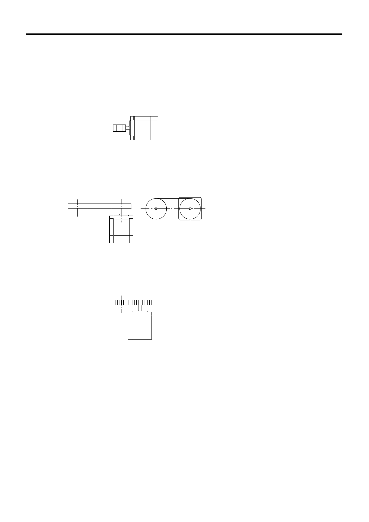
Installing a load
When connecting a load to the motor, align the centers of the motor’s output shaft and load
shaft.
Optional flexible couplings are available (sold separately).
Direct coupling
Align the centers of the motor’s output shaft and load shaft in a straight line.
Using a belt drive
Align the motor’s output shaft and load shaft in parallel with each other, and position both
pulleys so that the line connecting their centers is at a right angle to the shafts.
Note
• When coupling the load to the
motor, pay attention to the
centering of the shafts, belt
tension, parallelism of the
pulleys, and so on.
Securely tighten the coupling
and pulley set screws.
• Be careful not to damage the
output shaft or the bearings
when installing a coupling or
pulley to the motor’s output
shaft.
• Do not modify or machine the
motor’s output shaft. Doing so
may damage the bearings and
destroy the motor.
Using a gear drive
Align the motor’s output shaft and gear shaft in parallel with each other, and let the gears mesh
at the center of the tooth widths.
Using a geared motor
With a geared motor, to connect a load to the gear output shaft having a key groove, first
provide a key groove on the load and fix the load with the gear output shaft using the supplied
key.
17
Page 18
Note
Failure due to fatigue may occur
if the motor’s bearings and
output shaft are subject to
repeated loading by an overhung
or thrust load that is in excess of
the permissible limit.
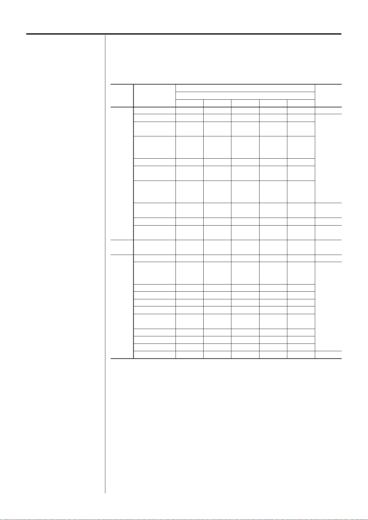
Overhung load and thrust load
The overhung load on the motor’s output shaft or gear output shaft must be kept within the
permissible values listed below.
The thrust load must not exceed the motor’s mass.
Frame
size
60 mm
(2.36 in.)
85 mm
(3.35 in.)
90 mm
(3.54 in.)
• The square box in the unit type will contain a value representing the gear ratio.
∗Calculate half the motor’s mass for this value.
Unit type
AS66-T
AS66-P5
AS66-P7.2
AS66-P10
AS66-P25
AS66-P36
AS66-P50
AS66-N5
AS66-N7.2
AS66-N10
AS66-N25
AS66-N36
AS66-N50
AS66A2-H
AS66M2-H
AS66-H
AS66
AS69
AS98
AS911
AS98-T
AS98-P5
AS98-P7.2
AS98-P10
AS98-P25
AS98-P36
AS98-P50
AS98-N5
AS98-N7.2
AS98-N10
AS98-N25
AS98-N36
AS98-N50
AS98-H
Distance from the tip of motor’s output shaft [mm (inch)]
0 (0)
70 (15.7)
200 (45)
250 (56)
330 (74)
200 (45)
250 (56)
330 (74)
320 (72)
300 (67)
63 (14.1)
260 (58)
220 (49)
480 (108)
850 (191)
930 (200)
1050 (230)
480 (108)
480 (108)
850 (191)
930 (200)
1050 (230)
1090 (240)
Overhung load [N (lb.)]
5 (0.2)
80 (18)
220 (49)
270 (60)
360 (81)
220 (49)
270 (60)
360 (81)
370 (83)
330 (74)
75 (16.8)
290 (65)
250 (56)
540 (121)
940 (210)
1030 (230)
1160 (260)
520 (117)
540 (121)
940 (210)
1030 (230)
1160 (260)
1150 (250)
10 (0.39)
100 (22)
250 (56)
300 (67)
400 (90)
250 (56)
300 (67)
400 (90)
440 (99)
370 (83)
95 (21)
340 (76)
300 (67)
600 (135)
1050 (230)
1150 (250)
1300 (290)
550 (123)
600 (135)
1050 (230)
1150 (250)
1300 (290)
1230 (270)
15 (0.59)
120 (27)
280 (63)
340 (76)
450 (101)
280 (63)
340 (76)
450 (101)
550 (123)
420 (94)
130 (29)
390 (87)
350 (78)
680 (153)
1 190 (260)
1310 (290)
1480 (330)
580 (130)
680 (153)
1110 (240)
1220 (270)
1380 (310)
1310 (290)
20 (0.79)
150 (33)
320 (72)
390 (87)
520 (117)
320 (72)
390 (87)
520 (117)
720 (162)
480 (108)
190 (42)
480 (108)
400 (90)
790 (177)
1380 (310)
1520 (340)
1710 (380)
620 (139)
790 (177)
1190 (260)
1300 (290)
1490 (330)
1410 (310)
Thrust
load
[N (lb.)]
40 (9)
100 (22)
470 (105)
400 (90)
∗
∗
100 (22)
300 (67)
1300 (290)
18
Page 19
Installing the driver
Orientation
The driver is designed so that heat is dissipated via air convection and conduction through the
enclosure.
When installing the driver in an enclosure, it must be placed in perpendicular (vertical)
orientation using a DIN rail or driver mounting brackets.
How to install the driver
Install the driver on a flat metal plate having excellent vibration resistance and heat
conductivity.
In the presence of a great amount of vibration, do not use a DIN rail. Screw down the driver
directly through the use of driver mounting brackets.
If a DIN rail is to be used, use a DIN rail mounting plate (sold separately).
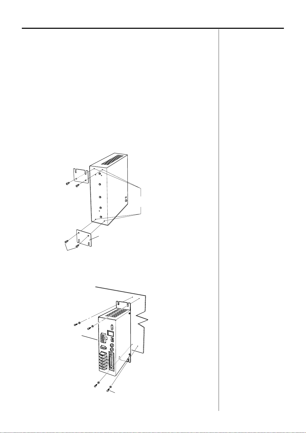
Using driver mounting brackets
1.Attaching the driver mounting brackets
Mounting holes for the driver
mounting brackets (M3, four locations)
Note
• Install the driver in an enclosure.
• Do not install any equipment
that generates a large amount
of heat near the driver.
• Check ventilation if the ambient
temperature of the driver
exceeds 50°C (122°F).
Note
• Do not use the mounting holes
(M3, four locations) for the driver
mounting brackets provided on
the back of the driver for any
purpose other than securing the
driver mounting brackets.
• Be sure to use the supplied
screws when securing the driver
mounting brackets.
Mounting brackets (two pieces)
Screws for driver mounting brackets M3 (provided)
Attach the driver mounting brackets to the four mounting holes provided in the back of the
driver, using optional screws for the driver mounting brackets (M3, four pieces).
2.Installing the driver
ASD24A-A
O
PER
ATIO
N
ALA
R
M
CN1
1000
500
X1
X
1
0
1P
2P
CURRENT
CN
2
M
O
TO
R
V.FIL
C
N
3
VEXTA
C
N
4
I/O
M4 (not supplied)
Install the driver by securing it with four bolts (M4, not supplied) through the four mounting holes
provided. Leave no gap between the driver and plate.
19
Page 20
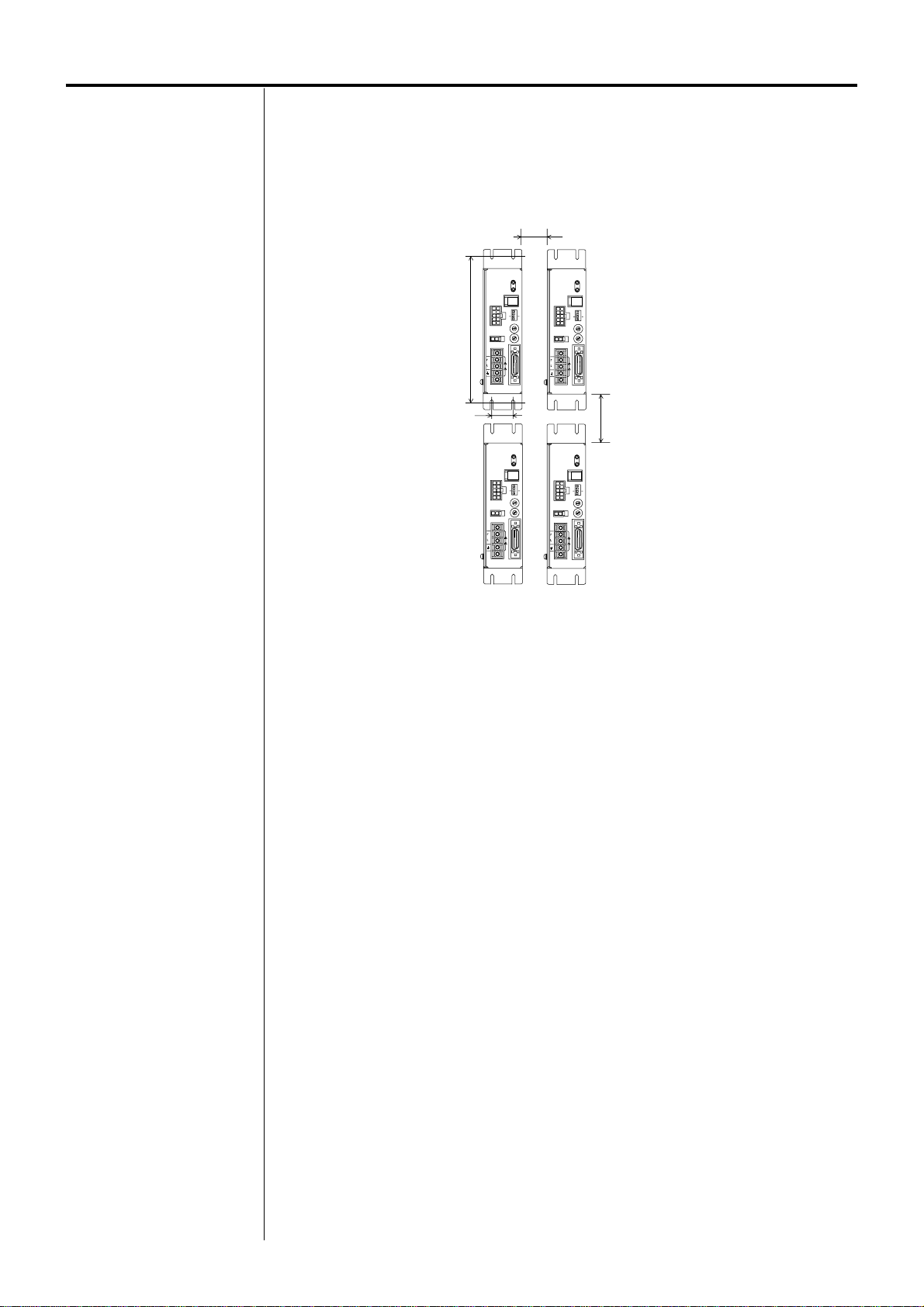
There must be a clearance of at least 25 mm (0.98 in.) in the horizontal and vertical directions,
respectively, between the driver and enclosure or other equipment within the enclosure.
When two or more drivers are to be installed side by side, provide 20 mm (0.79 in.) and 25 mm
(0.98 in.) clearances in the horizontal and vertical directions, respectively.
20 mm (0.79 in.) minimum
25 mm
(0.98 in.)
ASD24A-A
OPERATION
CN1
CN2
MOTOR
(7.09 in.)
CN3
L
100115V
~
N
180 mm
VEXTA
ASD24A-A
OPERATION
CN2
MOTOR
CN3
L
100115V
~
N
VEXTA
ASD24A-A
ALARM
500
1000
X1
X10
2P
1 2 3 4
1P
CURRENT
B
C
A
D
9
E
8
F
0
7
1
6
2
5
3
4
V.FIL
B
C
A
D
9
E
8
F
0
7
1
6
2
5
3
4
CN4
I
O
/
OPERATION
ALARM
CN1
500
1000
X1
X10
2P
1 2 3 4
1P
CURRENT
B
C
A
D
9
E
CN2
8
F
0
7
1
MOTOR
6
2
5
3
4
V.FIL
B
C
A
D
9
E
8
F
0
7
1
6
2
5
3
4
CN3
L
100115V
~
N
CN4
I
O
/
VEXTA
25 mm (0.98 in.) minimum
ASD24A-A
ALARM
CN1
1000
X1
1 2 3 4
1P
CURRENT
B
C
A
D
9
8
7
6
2
5
3
4
V.FIL
B
C
A
D
9
8
7
6
2
5
3
4
CN4
I
O
/
OPERATION
ALARM
CN1
500
X10
2P
E
F
0
1
E
F
0
1
500
1000
X1
X10
2P
1 2 3 4
1P
CURRENT
B
C
A
D
9
E
CN2
8
F
0
7
1
MOTOR
6
2
5
3
4
V.FIL
B
C
A
D
9
E
8
F
0
7
1
6
2
5
3
4
CN3
L
100115V
~
N
CN4
I
O
/
VEXTA
20
Page 21

Mounting to DIN rail
Use a DIN rail 35 mm (1.38 in.) wide to mount the driver.
1.Attach the DIN rail mounting plate (model number: PADP01) to the back of the driver using
the screws supplied with the plate.
DIN rail mounting plate
Mounting holes for the DIN rail
mounting plate (M3, three locations)
Mounting screws (M3)
2.Pull the DIN lever down, engage the upper hooks of the DIN rail mounting plate over the DIN
rail, and push the DIN lever until it locks in place.
DIN rail
Note
• Do not use the mounting holes
(M3, three locations) for the DIN
rail mounting plate provided in
the back of the driver for any
purpose other than securing the
DIN rail mounting plate.
• Be sure to use the supplied
screws when securing the DIN
rail mounting plate. The use of
screws that would penetrate
3 mm (0.12 in.) or more through
the surface of the driver may
cause damage to the driver.
DIN lever
3.Removing from DIN rail
Pull the DIN lever down until it locks using a flat blade-parallel tip type screwdriver, and lift
the bottom of the driver to remove it from the rail.
ASD24A-A
OPERATION
ALARM
CN1
500
1000
X1
X10
2P
1 2 3 4
1P
CURRENT
C
B
D
A
E
9
CN2
F
8
0
7
1
MOTOR
6
2
5
3
4
V.FIL
C
B
D
A
E
9
F
8
0
7
1
6
2
5
3
4
CN3
L
100115V
~
N
VEXTA
CN4
I
O
/
End plate
Note
• Use force of about 10 to 20 N
(2.2 to 4.41 lb.) to pull the DIN
lever to lock it. Excessive force
may damage the DIN lever.
• Use an end plate (not supplied)
to secure the driver.
21
Page 22

Installing and wiring in compliance with EMC directive
General
EMC directive (89/336/EEC, 92/31/EEC)
The AS series has been designed and manufactured for incorporation in general
industrial machinery. The EMC directive requires that the equipment incorporating this product
comply with these directives.
The installation and wiring method for the motor and driver are the basic methods that would
effectively allow the customer’s equipment to be compliant with the EMC directive.
The compliance of the final machinery with the EMC directive will depend on such factors as
the configuration, wiring, layout and risk involved in the control-system equipment and
electrical parts. It therefore must be verified through EMC measures by the customer of the
machinery.
Applicable standards
EMI
Emission Tests EN50081-2
Radiated Emission Test EN55011
Conducted Emission Test EN55011
EMS
Immunity Tests EN61000-6-2
Radiation Field Immunity Test IEC61000-4-3
Electrostatic Discharge Immunity Test IEC61000-4-2
Fast Transient/Burst Immunity Test IEC61000-4-4
Conductive Noise Immunity Test IEC61000-4-6
Surge Immunity Test IEC61000-4-5
Voltage Dip Immunity Test IEC61000-4-11
Voltage Interruption Immunity Test IEC61000-4-11
Note
When measuring dielectric
strength of the equipment, be
sure to remove the surge
arrester, or the surge arrester
may be damaged.
22
Installing and wiring
Effective measures must be taken against the EMI that the AS series may give to
adjacent control-system equipment, as well as the EMS of the AS series itself, in
order to prevent a serious functional impediment in the machinery.
The use of the following installation and wiring methods will enable the AS series
to be compliant with the EMC directive (the aforementioned compliance standards).
Connecting mains filter for power source line
Connect a mains filter in the AC input line to prevent the noise generated in the driver from
propagating externally through the power-source line.
Use a mains filter or equivalent as below table.
Manufacturer
Schaffner Electronik AG
EPCOS
Install the mains filter as close to the driver as possible, and use cable clamps and other means
to secure the input and output cables firmly to the surface of the enclosure. Connect the ground
terminal of the mains filter to the grounding point, using as thick and short a wire as possible.
Do not place the AC input cable (AWG18: 0.75 mm
cable (AWG18: 0.75 mm
the enclosure’s internal noise is directly coupled to the power-supply cable by means of stray
capacitance.
Connecting surge arrester
Use a surge arrester or equivalent as below table.
Manufacturer
OKAYA ELECTRIC INDUSTRIES CO., L TD
PHOENIX CONTACT GmbH & Co. KG
Power supply for electromagnetic brake (for electromagnetic-brake motor only)
If an external DC power source is required for the use of the electromagnetic brake, use a DC
power source that complies with the EMC directive.
Use a shielded cable for wiring, and keep the wiring and grounding as short as possible. Refer
to “Wiring the signal cable” for details on how to ground the shielded cable.
Single-phase 100-115 V
Single-phase 200-230 V
FN2070-10-06
B84113-C-B110
2
2
or more). Parallel placement will reduce mains-filter effectiveness if
or more) parallel with the mains-filter output
Single-phase 100-115 V
PT2-PE/S120AC-ST
Three-phase 200-230 V
FN251-8-07
-
Single-phase 200-230 V
R·A·V-781BWZ-2A
PT2-PE/S230AC-ST
VAL-MS 230 VF ST
Page 23

How to ground
The cable used to ground the driver, motor and mains filter must be as thick and short to the
grounding point as possible so that no potential difference is generated. Choose a large, thick
and uniformly conductive surface for the grounding point.
How to ground the driver
Single-phase 100/200 V input
Three-phase 200 V input
Ground the power-supply
terminal using its ground
terminal.
ASD24A-A
CN2
MOTOR
C
L
-
100
V
115
~
N
VEXTA
OPERATION
ALARM
CN1
0
0
5
4
3
0
0
1
0
X
0
1
2
1
1
X
ON
P
2
P
1
D
E
C
F
0
B
1
A
2
CURRENT
9
3
8
4
7
5
6
D
E
C
F
0
B
1
V.FIL
A
2
9
3
8
4
7
5
6
3
N
Use the protective earth
terminal located on the side
4
CN
I/O
of the driver.
ASD12A-S
CN2
MOTOR
3
N
C
L1
L2
L3
VEXTA
CN1
OPERATION
CURRENT
ALARM
0
0
5
4
3
0
0
1
0
X
0
1
2
1
1
X
ON
P
2
P
1
D
E
C
F
0
B
1
A
2
9
3
8
4
7
5
6
D
E
C
F
0
B
1
V.FIL
A
2
9
3
8
4
7
5
6
4
CN
I/O
How to ground the motor
Scrape the paint away from the mounting flange and connect the grounding cable along with a
set screw to the grounding point, using an inner-clip washer.
Wiring the signal cable
Use a shielded cable of AWG24 (0.2 mm
keep it as short as possible. Contact the nearest sales office for a shielded cable (sold separately).
To ground a shielded cable, use a metal clamp or similar device that will maintain contact with
the entire circumference of the shielded cable. Attach a cable clamp as close to the end of the
cable as possible, and connect it to an appropriate grounding point as shown in the figure.
2
) or more in diameter for the driver signal cable, and
Shielded cable
Cable clamp
Others
• Connect the motor, driver and other peripheral control equipment directly to the grounding
point so as to prevent a potential difference from developing between grounds.
• When relays or electromagnetic switches are used together with the system, use mains filters
and CR circuits to suppress surges generated by them.
• Keep cables as short as possible without coiling and bundling extra lengths.
• Place the power cables such as the motor and power-supply cables as far apart [100 to
200 mm (3.94 to 7.87 in.)] as possible from the signal cables. If they have to cross, cross
them at a right angle.
Place the AC input cable and output cable of a mains filter separately from each other.
• If an extension cable is required between the motor and driver, it is recommended that an
optional extension cable (sold separately) be used, since the EMC measures are conducted
using the Oriental Motor extension cable.
23
Page 24

Example of motor and driver installation and wiring
Power input
L
N
Motor
F
D
A
G
B
F
F
Driver
ASD24A-A
OPERATION
C
C
ALARM
CN1
500
1000
X1
X1
TEST
NORM.
2P
1 2 3 4
1P
CURRENT
C
D
B
A
E
9
F
CN2
8
0
7
1
MOTOR
6
2
5
3
4
V.FIL
C
D
B
A
E
9
F
8
0
7
1
6
2
5
3
4
CN3
L
100-
~
115V
N
CN4
I
O
/
VEXTA
E
C
D
A: Motor cable
B: Mains filter
C: Cable clamp
D: Protective earth cable
E: Signal cable
F: Power cable
G: Surge arrester
Note
Do not come close to or touch
the driver while the power is on.
24
Precautions about static electricity
Static electricity may cause the driver to malfunction or suffer damage. Be careful when
handling the driver with the power on.
Always use an insulated screwdriver to adjust the driver’s built-in motor current switch.
Page 25

Connection
This section covers the methods and examples of connecting and grounding the driver, motor,
power and controller, as well as the control input/output.
Connection example for a standard type
Motor cable or extension cable (sold separately)
Motor
Connect to
CN2
Single-phase
100-115 V
50/60 Hz
+
10%
−
15%
Power input
Driver
OPERATION
ALARM
CN1
1000
X1
1P
CURRENT
CN2
MOTOR
V.FIL
CN3
L
100115V
~
N
VEXTA
Protective earth
500
X10
2P
1 2 3 4
C
D
B
E
A
9
F
8
0
7
1
6
2
5
3
4
C
D
B
E
A
9
F
8
0
7
1
6
2
5
3
4
CN4
I
O
/
Control input/output
Controller
Connect to CN4
Connection example for an electromagnetic-brake type
Power supply for an electromagnetic brake
+
24 VDC±5%
0.3 A or more
Control input/output
Controller
Connect to CN4
Extension cable, electromagnetic-brake type
(sold separately)
Motor
Connect to CN2
Single-phase
100-115 V
50/60 Hz
+
10%
−
15%
Power input
Orange/black
Gray
Varistor (supplied)
Driver
OPERATION
ALARM
CN1
1000
X1
1P
CURRENT
CN2
MOTOR
V.FIL
CN3
L
100115V
~
N
VEXTA
Protective earth
C
B
A
9
8
7
6
5
4
C
B
A
9
8
7
6
5
4
CN4
I
/
D
3
D
3
O
500
X10
2P
1 2 3 4
E
F
0
1
2
E
F
0
1
2
Switch
Note
Be sure to use the extension
cable for the electromagneticbrake type (sold separately) to
connect the motor with an
electromagnetic brake.
25
Page 26

Note
Be sure to use the same voltage
for C.OFF, ×10 and ACL inputs
and TIM1/TIM2, ASG1/ASG2
and BSG1/BSG2 outputs.
Connecting both 5 and 24 VDC
power supplies may damage the
driver and power supplies.
Connecting the driver
• Either 5 or 24 VDC is selected as a signal voltage for the C.OFF input, ×10 input and ACL input.
• The TIM1/TIM2 outputs, ASG1/ASG2 outputs and BSG1/BSG2 outputs require a 5 or 24 VDC power.
In case of current sourcing inputs and current sinking outputs
When ACL, resolution select, C.OFF controller power supply is 5 VDC.
Controller
+30 V maximum
+5 V
Twisted pair cable
or shielded cable
Vcc+5 V input
CN4
CW input
CW input
CCW input
CCW input
ACL input
ACL input
×10 input
×10 input
C.OFF input
C.OFF input
GND
ALARM output
ALARM output
END output
END output
TIM1 output
GND
ASG1 output
GND
BSG1 output
GND
Driver
11
12
9
10
21
22
31
32
33
34
1
2
25
26
29
30
23
24
15
16
13
14
Photocoupler input
5 VDC Input current 7~20 mA
Photocoupler input
5 VDC Input current 16 mA
Photocoupler/open-collector output
30 VDC, maximum
Output current 15 mA, maximum
Transistor/open-collector output
30 VDC, maximum
Output current 15 mA, maximum
TIM2 output
TIM2 output
ASG2 output
ASG2 output
BSG2 output
BSG2 output
27
28
19
20
17
18
Line-driver output
26C31 or equivalent
When ACL, resolution select, C.OFF controller power supply is 24 VDC.
CN4
11
12
10
22
32
34
25
26
29
30
23
24
15
16
13
14
Driver
9
3
2
Photocoupler input
5 VDC Input current 7~20 mA
Photocoupler input
24 VDC Input current 5 mA
Photocoupler/open-collector output
30 VDC, maximum
Output current 15 mA, maximum
Transistor/open-collector output
30 VDC, maximum
Output current 15 mA, maximum
Controller
+24 V
+30 V maximum
+5 V
Twisted pair cable
or shielded cable
Vcc+24 V input
ALARM output
ALARM output
CW input
CW input
CCW input
CCW input
ACL input
×10 input
C.OFF input
GND
END output
END output
TIM1 output
GND
ASG1 output
GND
BSG1 output
GND
26
TIM2 output
TIM2 output
ASG2 output
ASG2 output
BSG2 output
BSG2 output
27
28
19
20
17
18
Line-driver output
26C31 or equivalent
Page 27

In case of current sinking inputs and current sourcing outputs
Controller
+5 V
Twisted pair cable
or shielded cable
Vcc+5 V input
CW input
CW input
CCW input
CCW input
ACL input
ACL input
×10 input
×10 input
C.OFF input
C.OFF input
GND
CN4
Driver
11
12
9
10
21
22
31
32
33
34
1
2
Photocoupler input
5 VDC Input current 7~20 mA
Photocoupler input
5 VDC Input current 16 mA
Note
Be sure to use the same voltage
for C.OFF, ×10 and ACL inputs
and TIM1/TIM2, ASG1/ASG2
and BSG1/BSG2 outputs.
Connecting both 5 and 24 VDC
power supplies may damage the
driver and power supplies.
∗ GND of TIM1, ASG1, BSG1
is common.
The output type of these signals
is current sinking outputs.
See page 39 for the wiring.
ALARM output
ALARM output
END output
END output
TIM1 output
GND
ASG1 output
GND
BSG1 output
GND
TIM2 output
TIM2 output
ASG2 output
ASG2 output
BSG2 output
BSG2 output
25
26
29
30
23
24
15
16
13
14
27
28
19
20
17
18
Photocoupler/open-collector output
30 VDC, maximum
Output current 15 mA, maximum
Transistor/open-collector output
30 VDC, maximum
Output current 15 mA, maximum
Line-driver output
26C31 or equivalent
27
Page 28

Note
• Furnish a power supply capable
of supplying adequate driver
input current.
If the current capacity is
insufficient, the transformer may
be damaged, or the motor may
run erratically due to a drop in
torque.
• Do not run the driver’s power
cable through a conduit
containing other power lines or
motor cables.
• After shutting down the power,
wait at least 10 seconds before
turning it back on, unplugging,
or plugging in the motor’s cable
connector.
Connecting to the power supply
Connect the power cable to the L and N terminals or the L1, L2 and L3 terminals of the
power-supply terminals located on the driver.
For single-phase 100-115 V unit
Connect the live side of the single-phase 100-115 V power cable to the L terminal and the
neutral side to the N terminal.
Connect the terminal to the grounding point of the power source.
L
Single-phase
100-115 V
50/60 Hz
Use a power supply capable of supplying the power/current capacity as shown below.
Unit name
Power/current capacity
AS66AA-T
AS66MA-T
AS66AA-P
AS66MA-P
AS66AA-N
AS66MA-N
AS66AA2-H
Single-phase 100-1 15 V
+10%
-
15%
AS66MA2-H
AS66AA-H
AS66MA-H
AS66AA
AS66MA
AS69AA
AS69MA
Single-phase 100-115 V
+10%
-
15%
AS98AA-T
AS98MA-T
AS98AA-P
AS98MA-P
AS98AA-N
AS98MA-N
Single-phase 100-1 15 V
+10%
-
15%
AS98AA-H
AS98MA-H
AS98AA
AS98MA
AS911AA
The square box in the unit model will contain a value representing the gear ratio.
Single-phase 100-115 V
+10%
-
15%
100115V
~
N
5 A or more
6.4 A or more
6 A or more
6.5 A or more
28
Page 29

For single-phase 200-230 V unit
Connect the live side of the single-phase 200-230 V power cable to the L terminal and the
neutral side to the N terminal.
Connect the terminal to the grounding point of the power source.
L
Single-phase
200-230 V
50/60 Hz
200230V
~
N
Use a power supply capable of supplying the power/current capacity as shown below.
Unit name
Power/current capacity
AS66AC-T
AS66MC-T
AS66AC-P
AS66MC-P
AS66AC-N
AS66MC-N
AS66AC2-H
Single-phase 200-230 V
+10%
3 A or more
-
15%
AS66MC2-H
AS66AC-H
AS66MC-H
AS66AC
AS66MC
AS69AC
AS69MC
Single-phase 200-230 V
+10%
3.9 A or more
-
15%
AS98AC-T
AS98MC-T
AS98AC-P
AS98MC-P
AS98AC-N
AS98MC-N
Single-phase 200-230 V
+10%
3.5 A or more
-
15%
AS98AC-H
AS98MC-H
AS98AC
AS98MC
AS911AC
Single-phase 200-230 V
The square box in the unit model will contain a value representing the gear ratio.
+10%
4.5 A or more
-
15%
29
Page 30

For three-phase 200-230 V unit
Connect the U, V and W phase lines of the three-phase 200-230 V power cable to the L1, L2
and L3 terminals, respectively.
Three-phase
200-230 V
50/60 Hz
L1
L2
L3
Use a power supply capable of supplying the power/current capacity as shown below.
Unit name
Power/current capacity
AS66AS-T
AS66MS-T
AS66AS-P
AS66MS-P
AS66AS-N
AS66MS-N
AS66AS2-H
Single-phase 200-230 V
+10%
1.5 A or more
-
15%
AS66MS2-H
AS66AS-H
AS66MS-H
AS66AS
AS66MS
AS69AS
AS69MS
Single-phase 200-230 V
+10%
2.2 A or more
-
15%
AS98AS-T
AS98MS-T
AS98AS-P
AS98MS-P
AS98AS-N
AS98MS-N
Single-phase 200-230 V
+10%
1.9 A or more
-
15%
AS98AS-H
AS98MS-H
AS98AS
AS98MS
AS911AS
The square box in the unit model will contain a value representing the gear ratio.
Single-phase 200-230 V
+10%
2.4 A or more
-
15%
30
T erminal screw size and cable size for power connection
Screw size: M3
Tightening torque: 0.8 to 1.0 N·m (113 to 141 oz-in)
Cable size capacity: AWG18 (0.75 mm
2
)
Use round, insulated crimp terminals for connection.
[Unit: mm (inch)]
Ø3.2 (0.13 DIA.) minimum
9 (0.35) minimum
6.2 (0.24) maximum
Page 31

Connecting the motor
Standard type
Plug the connector of the motor cable or the extension cable into the driver’s motor connector
(CN2).
Push the plug until it clicks to ensure a solid connection.
ASD24A-A
OPERATION
M
LAR
A
1
CN
500
4
3
X10
1000
2
1
X1
N
O
2P
1P
D
E
C
F
0
B
1
A
2
CURRENT
9
3
8
4
7
5
6
CN2
D
E
C
F
0
B
1
V.FIL
MOTOR
A
2
9
3
8
4
7
5
6
3
N
C
Motor connector
(CN2)
L
100115V
~
N
VEXTA
4
N
C
I/O
Motor cable
Extension cable
Use an optional extension cable (sold separately) to extend the distance between the motor
and driver.
Connector
Note
• Have the connector plugged in
securely.
Insecure connector connection
may cause malfunction or
damage to the motor or driver.
• To disconnect the plug, pull the
plug while using the fingers to
press the latches on the plug.
• When the motor is to be
installed in a moving part,
thereby subjecting the motor
cable to repeated bending and
stretching, use an optional
flexible cable (sold separately).
Refer to page 61 of “Appendix”
for the flexible cable.
Refer to page 61 of “Appendix” for the extension cable.
Electromagnetic-brake type
Plug the connector of the extension cable into the driver’s motor connector (CN2).
Push the plug until it clicks to ensure connection.
ASD24A-A
N
OPERATIO
RM
ALA
CN1
500
4
3
X10
1000
2
1
X1
N
O
2P
1P
D
E
C
F
0
B
1
A
Motor connector
(CN2)
L
100115V
~
N
CN2
MOTOR
3
N
C
VEXTA
2
CURRENT
9
3
8
4
7
5
6
D
E
C
F
0
B
1
V.FIL
A
2
9
3
8
4
7
5
6
4
N
C
I/O
Connector
Electromagnetic-brake-type
extension cable
Refer to page 61 of “Appendix” for the extension cable.
Note
Be sure to purchase and use an
optional electromagnetic-braketype extension cable (sold
separately) to connect an
electromagnetic-brake-type
motor to the driver.
Direct connection to the motor
cable will not operate the brake.
31
Page 32

Note
+24 V
GND
DC power supply for
electromagnetic brake
Varistor (provided)
GrayOrange/black
Electromagnetic-brake-type extension cable
(sold separately)
Gray
Orange/black
+24 V
GND
DC power supply for
electromagnetic brake
Varistor (provided)
Orange Gray
Electromagnetic-brake-type flexible cable
(sold separately)
Orange
Gray
• Applying a voltage over the
specification will increase the
temperature rise in the
electromagnetic brake and may
damage the motor.
Conversely, insufficient voltage
may prevent the brake from
releasing.
• Be sure to connect the varistor
(non-polarized) to protect the
switch contacts and prevent
noise.
• The lead wires for the
electromagnetic brake are
polarized. Connecting the lead
wires in reversed polarity will not
properly operate the
electromagnetic brake.
Connecting power supply for the electromagnetic brake
Provide a DC power-supply cable of 24 VDC±5% at 0.3 A or more.
Use a shielded cable of AWG24 (0.2 mm
2
) or more in diameter to connect the electromagnetic
brake to the DC power supply, keeping the length as short as possible.
Using an electromagnetic-brake-type extension cable (sold separately)
Model: CC01AIPM, CC02AIPM, CC03AIPM, CC05AIPM, CC07AIPM, CC10AIPM,
CC15AIPM, CC20AIPM
Use two (orange/black and gray) lead wires [60 mm (2.36 in.)] from the driver’s connector side.
1. Connect the orange/black lead wire to the +24 V terminal of the DC power supply.
2. Connect the gray lead wire to the GND terminal of the DC power supply.
3. Connect the varistor in parallel across the +24 V and GND terminals of the DC power supply.
The varistor is non-polarized.
Using an electromagnetic-brake-type flexible cable (sold separately)
Model: CC01SARM2, CC02SARM2, CC03SARM2,
CC05SARM2, CC07SARM2, CC10SARM2
Use two (orange and gray) lead wires [60 mm (2.36 in.)] from the driver’s connector side.
1.Connect the orange lead wire to the +24 V terminal of the DC power supply.
2.Connect the gray lead wire to the GND terminal of the DC power supply.
3.Connect the varistor in parallel across the +24 V and GND terminals of the DC power supply.
The varistor is non-polarized.
32
Page 33

Grounding the motor and driver
Grounding the motor
Ground the motor using one of its four mounting holes.
Use a grounding cable of AWG18
Use a round, insulated crimp terminal in combination with an inner-clip washer and bolt it in
place to secure the grounding connection.
Grounding the driver
Be sure to ground the protective earth terminal (screw size: M4) located on the driver side.
Use a grounding cable of AWG18
Do not share the grounding cable with a welder or power equipment.
Use a round, insulated crimp terminal to ground the cable near the driver.
(0.75 mm2) or more in diameter.
(0.75 mm2) or more in diameter.
Protective earth terminal
P.E.
Connecting control input/output
Connecting control input/output connector
Connect the control input/output connector (supplied, 36 pins) to the driver.
Solder the control input/output cable (AWG28: 0.08 mm
the connector and connector cover with the supplied screws.
Use a shielded cable, such as the optional shielded cable with connectors (sold separately).
Refer to “Assembling the control input/output connector” on page 34.
Insert the control input/output connector into the control input/output connector CN4 on the
driver side, and tighten the screw with a flat blade-parallel tip type screwdriver.
E
D
F
0
C
T
N
1
B
E
R
2
R
A
U
C
3
9
4
8
5
7
6
CN2
E
D
F
0
C
IL
.F
1
V
B
MOTOR
2
A
3
9
4
8
5
7
6
3
N
C
L
100115V
~
N
2
or more) to the connector. Assemble
Control input/output connector (CN4)
Control input/output connector
Screws
CN4
I/O
Tightening torque: 0.3 to 0.35 N·m (42.5 to 49.6 oz-in)
33
Page 34

Assembling the control input/output connector
Half-pitch connector
Connector pin
Solder the control input/output cable to the half-pitch connector (36 pins), then install the
connector cover over the half-pitch connector.
Soldering the cable to the half-pitch connector
Solder the input/output signal cable
(AWG28: 0.08 mm2 or more) to the half-pitch connector
(36 pins).
For the pin assignments, refer to page 35.
Assembling the half-pitch connector and the connector cover
1. Attach the supplied screws (two pieces) to the connector cover and insert the half-pitch
connector with the control input/output cable soldered to it. Adjust the cable clamp to its
correct position.
Connector cover
Half-pitch connector
Screw
Cable clamp
Screw (M2)
Control input/output cable
Place the spring washer outside the connector cover.
Align the washer in the depression in the connector cover.
2. Attach the other connector cover and clamp both connector covers together with screws
and nuts.
Clamp with screws (M2.5) and hexagonal nuts.
Tightening torque: 0.5 to 0.55
N·m (70.8 to 77.9 oz-in)
34
Page 35

Connector pin functions
Pin No.
1
2
3
4
5
6
7
8
9
10
11
12
13
14
15
16
17
18
19
20
21
22
23
24
25
26
27
28
29
30
31
32
33
34
35
36
Signal
Vcc+5 V
GND
Vcc+24 V
-
-
-
-
CCW (DIR)
CCW (DIR)
CW (PLS)
CW (PLS)
BSG1
GND
ASG1
GND
BSG2
BSG2
ASG2
ASG2
ACL
ACL
TIM1
GND
ALARM
ALARM
TIM2
TIM2
END
END
×10
×10
C.OFF
C.OFF
-
-
Description
5 VDC
GND
24 VDC
External power
source
Not used
Not used
Not used
Not used
Not used
CCW pulse
(ON: CW, OFF: CCW)
CW pulse
(Pulse)
B-phase pulse output
Open-collector
A-phase pulse output
Open-collector
B-phase pulse output
Line driver
A-phase pulse output
Line driver
Alarm clear
Timing
Open-collector
Alarm
Timing
Line driver
Positioning complete
Resolution switch
All Windings Off
Not used
Not used
Direction
Input
-
-
-
-
-
Input
Input
Output
Output
Output
Output
Input
Output
Output
Output
Output
Input
Input
-
-
Note
• The functions shown in
parentheses are enabled when
“1P: 1-Pulse Input Mode” is
selected through the pulseinput mode selector switch.
• Be sure to use the same
voltage for C.OFF, ×10 and ACL
inputs and TIM1/TIM2, ASG1/
ASG2 and BSG1/BSG2
outputs.
Connecting both 5 and 24 VDC
power supplies may damage
the driver and power supplies.
Connector pin assignments
2 4
810
12 14
18
16
131517
18
36
32
36
34
30
3335
31
Viewed from the soldering side
6
9
11
28
26
29
1
357
22
24
20
19
232527
21
1
19
35
Page 36

Note
Be sure to use the same voltage
for C.OFF, ×10 and ACL inputs
and TIM1/TIM2, ASG1/ASG2
and BSG1/BSG2 outputs.
Connecting both 5 and 24 VDC
power supplies may damage the
driver and power supplies.
Note
• If no pulse is to be input, be sure
to keep the photocoupler in
“OFF” state.
Do not input a CW pulse and
CCW pulse simultaneously.
If a pulse is input while the other
photocoupler is in the “ON” state,
the motor will not operate
properly.
• The direction of rotation is
defined as the rotation direction
of the motor shaft.
The output shaft of the TH geared
typed motors with ratios of 20:1
and 30:1, as well as all ratios of
the harmonic geared type
motors, rotate in the opposite
direction of the motor shaft.
About control input/output
Input signals
All input signals of the driver are photocoupler inputs.
For C.OFF input, ×10 input and ACL input a signal voltage of either 5 or 24 VDC can be
selected. Be sure to use it with voltage of either 5 or 24 VDC.
The signal state represents the “ON: Carrying current” or “OFF: Not carrying current” state of
the internal photocoupler rather than the voltage level of the signal.
The following explains the connection state in the case of current sink input.
CW, CCW ACL, ×10, C.OFF
Driver internal circuit
9, 11
10, 12
CW pulse input and CCW pulse input
220 Ω
7∼20 mA
21, 31, 33
22, 32, 34
Driver internal circuit
5 mA
220 Ω
16 mA
4.7 kΩ
3
With this driver either 2-pulse input mode or 1-pulse input mode may be selected in accordance
with the controller used. Refer to page 44 for details on how to set the pulse-input mode.
ALARM output is in the “OFF” state immediately after the driver power is turned on. Check to
see that ALARM output has been turned from “OFF” to “ON” before inputting pulse signals.
For the electromagnetic-brake type, wait at least 0.1 second after releasing the
electromagnetic brake, then input pulse signals.
When an electromagnetic brake type is used, also refer to “Operating the electromagnetic brake”
at the end of this section.
2-pulse input mode (factory setting)
Connect the CW pulse and CCW pulse of the controller to pin No.12, “CW input,” and pin No.
10, “CCW input,” respectively.
1.When the CW pulse input changes from the “OFF” state to “ON” state, the motor will
rotate one step in the CW direction.
2.When the CCW pulse input changes from the “OFF” state to “ON” state, the motor will
rotate one step in the CCW direction.
CW pulse input
CCW pulse input
ON
OFF
ON
OFF
∗
∗The minimum interval time needed for
switching the direction of rotation will
vary, depending on the operating speed
and size of the load.
Do not shorten the interval time any more
than is necessary.
36
CW
Motor operation
CCW
Set the input pulse voltage to the CW and CCW pulse inputs at 5 VDC.
If the voltage exceeds 5 VDC, insert an external resistor to limit the input current to nearly
10 mA.
V-1.5
R =
10 mA
-
220 [Ω]
Use an input-pulse signal with a waveform having a sharp rise and fall, as shown in the figure:
H
90%
10%
L
2 µs minimum
1 µs minimum
2 µs maximum 2 µs maximum
H: 4~5 V
L: 0~0.5 V
The figure shows the voltage levels of pulse signals.
Page 37

1-pulse input mode
Connect the pulse signal of the controller to pin No.11 and No.12, and the rotating direction
signal to pin No.9 and No.10, respectively.
1.When the DIR input is “ON,” a rise of the “PLS input” from “OFF” to “ON” will rotate the
motor one step in the CW direction.
2.When the DIR input is “OFF,” a rise of the “PLS pulse input” from “OFF” to “ON” will rotate
the motor one step in the CCW direction.
∗
∗The minimum interval time needed for
switching the direction of rotation will
vary, depending on the operating speed
CCW
CCW
and size of the load.
Do not shorten the interval time any more
than is necessary.
PLS input
(Pulse)
DIR input
(Rotating direction)
Motor operation
ON
OFF
ON
OFF
CW
CW
The voltage of pulse and rotation direction input to the PLS input and DIR input shall be 5 VDC.
If the voltage exceeds 5 VDC, connect an external resistor to limit the input current to nearly
10 mA.
V-1.5
R = - 220 [Ω]
10 mA
Use an input pulse signal with a waveform having a sharp rise and fall, as shown in the figure:
H
90%
10%
L
2 µs minimum
1 µs minimum
2 µs maximum 2 µs maximum
H: 4~5 V
L: 0~0.5 V
The figure shows the voltage levels of pulse signals.
37
Page 38

Note
• Normally, keep the C.OFF input
in the “OFF” state or leave it
disconnected.
• Turning the C.OFF input to
“ON” resets the deviation
counter in the driver.
Note
Be sure to set the resolution
selection switch to “×1” when
“×10 input” is used.
If the switch is set to “×10,” the
resolution will remain at 10
times, regardless of the “ON” or
“OFF” resolution-selector input.
C.OFF (All windings off) input
Use the signal only when the motor’s output shaft must be rotated manually for position
adjustment.
Warning
• Do not turn the C.OFF (All windings off) input to “ON” while the motor is
operating. The motor will stop and lose its holding ability, which may result
injury or damage to equipment.
1.When the C.OFF input is turned “ON,” the driver will shut off the output current and the
motor will lose its excitation holding torque.
This, however, will allow you to adjust the load position manually.
2.When the C.OFF input is turned “OFF,” the driver will turn the output current to “ON” again
and the motor’s excitation holding torque will be restored.
The C.OFF input must be “OFF” when operating the motor.
×10 (Resolution selection) input
Selects and switches to 10 times either of the resolution “500: 0.72°/pulse” or “1000: 0.36°/
pulse” that has been selected with the resolution selection switch.
For instance, if “1000: 0.36°/pulse” has been selected, this signal can switch between the
0.36° step rotation and 0.036° step rotation.
Refer to page 43 for the selection of the resolution selection switch.
1.Turning the ×10 input to “ON” will select/switch to “×10 resolution.”
Note
• The overcurrent protection,
EEPROM data error and
system error protective
functions cannot be cleared.
When any of these functions
are triggered, contact the
nearest customer-service
center, branch or sales office.
• Turning the power back on will
clear the ALARM output.
To cancel the ALARM output,
be sure to remove the cause of
the problem that has triggered
the protective function before
turning the power back on.
After the power has been shut
off, wait at least 10 seconds
before turning the power back
on.
2.Turning the ×10 input to “OFF” will select/switch to “×1 resolution.”
1000
X1
1P
ACL (Alarm clear) input
The input clears the ALARM output issued when a protective function has been triggered.
The ALARM output remains “ON” when the driver is operating normally , then turns “OFF” when
a protective function is triggered. For details, refer to “ALARM output” on page 39 and
“Protective function” on page 46.
Setting the ACL input in the ON state clears the ALARM output.
To cancel the ALARM output, be sure to remove the cause of the problem that has triggered the
protective function before turning the power back on.
ACL input
(Alarm clear)
ALARM output
(Alarm)
500
X10
1 2 3 4
2P
ON
OFF
OFF
0.1 s minimum
ON
Resolution selection switch
0.5 s maximum
38
Page 39

Output signals
Driver output signals are photocoupler/open-collector output, transistor open-collector output
for the TIM1, ASG1 and BSG1 outputs, and line-driver output for the TIM2, ASG2 and BSG2
outputs.
The signal state represents the “ON: Carrying current” or “OFF: Not carrying current” state of
the internal photocoupler rather than the voltage level of the signal.
Note
Be sure to use the same voltage
for C.OFF, ×10 and ACL inputs
and TIM1/TIM2, ASG1/ASG2
and BSG1/BSG2 outputs.
ALARM, END
Driver internal circuit
25, 29
26, 30
30 VDC 5 mA maximum
ALARM output
Line driver output
Open-collector output
TIM1, TIM2, ASG1, ASG2, BSG1, BSG2
Driver internal
1
3
2
17, 19, 27
18, 20, 28
13, 15, 23
14, 16, 24
circuit
26C31 or
equivalent
30 VDC
15 mA maximum
+5 V
ALARM output remains “ON” when the driver is operating normally, then turns “OFF” when a
protective function is triggered.
Detect this ALARM output on the controller side and cancel the command to operate the motor
thereafter.
Error detection by the driver, such as overload and overcurrent during motor operation, turns
the ALARM output “OFF,” blinks the ALARM LED on the driver, and simultaneously shuts off the
motor current to stop motor operation.
Count the number of the ALARM LED blinks to identify the particular protective function that has
been triggered. For details, refer to “Protective functions” on page 46.
Note
The operation of the
photocoupler is reversed on the
ALARM output only. The ALARM
output turns “OFF” when
protective function is triggered.
Blink
ALARM LED
(Alarm)
ON
OFF
The motor stops due to inertial force.
ALARM output
Motor movement
When the driver is operating normally. When a protective function is triggered.
END (Positioning complete) output
END output turns “ON” when motor movement is complete.
Conditions for the issuance of END output are as follows:
END output is issued when the pulse speed is 500 Hz or less, and the rotor has positioned
within ±1.8° of the commanded position.
Motor operation
END output
(Positioning complete)
Movement
ON
OFF
Movement
Stop Stop
Note
The timing of the END output
turning “ON” after the pulse stops
will vary, depending on the
conditions of the load, the pulse
input, and the speed-filter
setting.
39
Page 40

Note
If TIM output is to be detected,
set the pulse speed at 500 Hz or
less.
Use the ×10 (resolution
selection) input to switch the
resolution only when TIM output
is in the “ON” state and the
motor stops.
If the resolution is switched
under any other conditions, TIM
output may not turn “ON” even
when the output shaft has
rotated 7.2°.
Note
The pulse-output delays behind
motor rotation by up to 1 ms.
The output may be used to verify
the motor’s stop position.
TIM (Timing) output
TIM output are available in two types: transistor open-collector output and line-driver output.
Use either one to suit the input system of the positioning controller.
The use of TIM output requires separate 5 or 24 VDC power.
TIM output turns “ON” whenever the motor’s output shaft rotates 7.2°.
Motor operation
TIM output
(Timing)
ASG output and BSG output
ON
OFF
Movement
Movement
Stop Stop
ASG and BSG outputs are available in two types: transistor open-collector output and linedriver output.
Use either type to suit the input system of the counter unit and other functions of the controller.
The use of ASG and BSG outputs requires separate 5 or 24 VDC power.
The output-pulse resolution will be the same as the motor resolution at the time power is
supplied to the driver (as set by the resolution selection switch).
Counting ASG output pulses allows the motor position to be monitored.
ASG1 output
BSG1 output
ON
OFF
90°
ON
OFF
ASG output:Outputs pulse while the motor operates.
BSG output:Detects the direction of motor rotation. It has a 90° phase difference with regard
to ASG output.
The level of BSG output at the rise time of ASG output indicates the direction of
motor rotation.
40
Page 41

Operating the electromagnetic brake
Operate the electromagnetic brake as follows:
1.ALARM output is in the “OFF” state immediately after the driver power is turned on.
Check to see that ALARM output has been reset (turned from OFF to ON), then turn on the
electromagnetic brake.
2.Before inputting pulse signals to operate the motor, set the motor in the ready state by
“releasing” the electromagnetic brake.
3.To allow the electromagnetic brake to “hold” the load after the motor has completed its
operation, turn the electromagnetic brake off only after verifying that END (positioning
complete) output has turned from “OFF” to “ON.”
Note
To hold the load in position, apply
the electromagnetic brake only
after the motor has stopped. Do
not use the brake to bring the
moving motor to a halt.
Repeated braking for such a
purpose will wear the brake hub
excessively, causing a decrease
in its ability to hold.
Driver power
ALARM output
Electromagnetic brake power
CW pulse input or CCW pulse input
END output
∗CCW pulse input is enabled when 2-pulse input mode is selected
About providing for ALARM output
ON
∗
OFF
ON
OFF
ON
OFF
ON
OFF
ON
OFF
0.5 s maximum
0 s minimum
Brake releasing
0.1 s minimum
When operation is started When operation is stopped
0.5 s minimum
0.1 s minimum
When the driver-protection function is triggered, the motor stops as the current is turned off.
The motor loses its holding ability, which in a vertical-travel application may cause the load to
fall.
The user must set a controller sequence that will cut off the power to the electromagnetic brake
and hold the load in position upon detecting an “OFF” ALARM output.
Backlash of the electromagnetic brake
There is a backlash between the electromagnetic brake and motor shaft, but it is structurally
necessary.
When the driver power comes back on, the position of the motor’s output shaft may differ from
the previous position, even though the position has been maintained by the electromagnetic
brake.
For that reason, after power-on be sure to detect the equipment’s home position before
resuming operation.
41
Page 42

Timing chart
Motor operation
Power input
ALARM output
(Alarm)
CW pulse input
CCW pulse input
END output
(Positioning complete)
TIM output
(Timing)
C.OFF input
(All windings off)
ON
OFF
ON
OFF
ON
OFF
ON
OFF
ON
OFF
ON
OFF
∗2
CW
0.5 s maximum
0.1 s minimum
∗4
CCW
∗3 ∗3
CW
10 s minimum
∗1
∗3
2 s minimum
∗5
∗1 After the power has been shut off, wait at least 10 seconds before turning the power back on.
∗2 To input the CW or CCW signal pulse, wait at least 0.1 second after clearing the ALARM output.
∗3 The turning of END output to “ON” does not necessarily mean the motor has stopped. Provide
enough of a time delay for a halt, which will vary, depending on the acceleration/deceleration rates and
load condition.
The time for END output to turn “ON” after the pulse signal stops will vary, depending on the
pulse-signal input condition and speed-filter setting condition.
∗4 Detect TIM output only at a pulse speed of 500 Hz or less.
No accurate detection is possible at a speed over 500 Hz.
∗5 Turning C.OFF input “ON” shuts off the motor current, at which time the motor loses its holding ability.
It also clears the value on the deviation counter.
42
Page 43

Setting
This section covers the selection and settings of driver functions.
The various switches provided on the driver’s front panel allow for the setting of resolution,
pulse-input mode, current level and speed filter.
Warning
• Before working on the system, shut off the power to the driver and wait 10
seconds. Failure to do so may result in electric shock.
Driver front panel
CN2
MOTOR
CN3
CN1
CURRENT
V.FIL
1000
500
X1
X10
2P
1 2 3 4
1P
C
D
B
E
A
F
9
8
0
7
1
6
2
5
3
4
C
D
B
E
A
F
9
8
0
7
1
6
2
5
3
4
Not used (CN1)
Resolution selection switch
Pulse-input mode selection switch
Current-adjustment switch
Speed-filter selection switch
Resolution
Use the resolution selection switch “1000/500” and “×1/×10” to set the motor resolution.
Factory settings
[1000]: 1000 P/R (0.36°/pulse)
[×1]: Multiplier 1
1000
X1
1P
500
X10
1 2 3 4
2P
Resolution selection switch
Note
• Be sure to shut off the power
before using the resolution
selection switch. The new
resolution takes effect when the
power is turned on again.
• Be sure to switch to “×1” when
resolution switching input is
used.
The “×10” setting disables
resolution switching input.
A total of four resolution levels may be selected, with ×10 (resolution selection) input “CN4 Pin
No. 31, 32” used to switch between 1,000 and 10,000 and between 500 and 5,000.
Refer to page 38 for the use of ×10 input (resolution selection).
Refer to “Main specifications” on page 50 to 60 for details of the relationship between the
setting of the resolution selection switch and resolution of the geared output shaft in the geared
type.
43
Page 44

Note
Be sure to shut off the power
before using the pulse-input
mode selection switch.
The new pulse mode takes effect
when the power is turned on
again.
Pulse input modes
Either the 2-pulse or 1-pulse input mode may be selected in accordance with the controller
used.
Factory setting
[2P]: 2-Pulse Input Mode
1000
X1
500
X10
Note
An excessively low operating
current level may cause a
problem when starting the motor
or holding the load in position.
Do not reduce the current any
more than is necessary.
1P
1 2 3 4
2P
Pulse-input mode selection switch
When the motor is to be controlled through 2-pulse signal input via the CW pulse signal and
CCW pulse signal, set the pulse-input mode selection switch to “2P.”
1P 2P
When the motor is to be controlled through the PLS (pulse) and the DIR (rotating-direction) , set
the pulse-input mode selection switch to “1P.”
1P 2P
Operating current
Use the operating-current adjustment switch “CURRENT” to set the motor’s operating current.
Set the operating current as a product of the maximum driver output current “F,” which is 100%,
multiplied by the operating current percentage corresponding to the given dial.
The switch provides a selection of 16 levels ranging between “0” and “F.”
If there is extra torque, the current may be set to a lower level in order to suppress increases in
motor temperature.
Factory setting
[F]: Driver’s maximum output-current value
CURRENT
V.FIL
C
D
B
E
A
F
9
8
0
7
1
6
2
5
3
4
C
D
B
E
A
F
9
8
0
7
1
6
2
5
3
4
Operating-current adjustment switch
44
The dial settings and corresponding levels of operating current rates are as follows:
Dial setting
0
1
2
3
4
5
6
7
8
9
A
B
C
D
E
F
Operating current rate [%]
6
13
19
25
31
38
44
50
56
63
69
75
81
88
94
100
Page 45

Speed filter
Use the speed-filter selection switch “V .FIL” to select the filter time constant that determines the
motor’s response to pulse input.
The switch provides a selection of 16 levels ranging between “0” and “F.”
When a larger value is selected, it will reduce shock when the motor is started and stopped, and
will minimize low-speed vibration.
An unnecessarily large filter time constant, however, will smooth out the motor movement
further but with a reduced ability to synchronize to the pulse input and extended settling time
when stopping. Select an optimal value to fit the load and application.
Factory setting
[6]: 1.20 ms
The dial settings and corresponding levels of filter time constants are as follows:
Dial setting
0
1
2
3
4
5
6
7
8
9
A
B
C
D
E
F
CURRENT
V.FIL
Filter time [ms]
None
0.12
0.16
0.27
0.41
0.82
1.20
1.60
2.70
4.10
8.20
12.0
16.0
27.0
41.0
82.0
C
D
B
E
A
F
9
8
0
7
1
6
2
5
3
4
C
D
B
E
A
F
9
8
0
7
1
6
2
5
3
4
Speed-filter selection switch
When the speed-filter selection switch is set to "0"
Command speed
Motor speed
END output
When the speed-filter selection switch is set to "E"
Command speed
Motor speed
END output
45
Page 46

Protective functions
123 123
Interval
1.2 s
0.2 s
0.2 s
This section covers the driver-protection functions and methods used to clear the triggered
function.
Note
・To clear the ALARM output, be
sure to remove the cause of
the problem that has triggered
the protective function before
either giving a one-shot ACL
input or turning the power back
on. After turning off the power,
wait at least 10 seconds before
turning the power back on.
・The overcurrent protection,
EEPROM data error and
system error protective
functions cannot be cleared.
When any of these functions
are triggered, contact the
nearest customer-service
center, branch or sales office.
Warning
• When the driver-protection function is triggered, the motor will stop and
lose its holding torque, possibly causing injury or damage to equipment.
• When the driver’s protection function is triggered, first remove the cause
and then clear the protection function. Continuing the operation without
removing the cause of the problem may cause malfunction of the motor,
leading to injury or damage to equipment.
Descriptions of protective functions and numbers of LED
blinks
The driver is provided with functions that protect the driver from ambient temperature increases,
improper power-source or motor-cable connections, and the occurrence of operating errors.
When a protective function is triggered, the ALARM LED on the front panel blinks, ALARM
output turns OFF, and simultaneously the motor current is shut off in order to stop the motor.
ALARM output remains “ON” when the dr i ver is operating normally, then turns “OFF” when a
protective function is triggered. For details, refer to “ALARM output” on page 39.
OPERATION
ALARM
ALARM LED blinking cycle (example: for overvoltage protection)
The number of ALARM LED blinks varies according to the nature of the triggered protective
function, thereby facilitating action and recovery from the abnormal conditions causing the
function to be triggered.
The table below gives descriptions of protective functions and their corresponding numbers of
blinks.
No. of blinks
1
2
3
4
5
6
Protective function
Overheat protection
Overload protection
Overvoltage protection
Speed error protection
Overcurrent protection
Overspeed
When a heat-radiating unit within the driver reaches
approx. 85°C.
When a load exceeding the maximum torque is applied
to the motor for five seconds or more.
When the driver inverter’s primary voltage exceeds a
permissible value.
When the motor has not normally followed up on pulse
input.
When an excessive current flows through the driver
inverter’s power element.
When the motor shaft speed exceeds 5000 r/min.
Blink
Conditions
46
7
8
Continuous
EEPROM data error
Sensor error
System error
When the motor parameter in the driver is damaged.
When power turns on without the connection of a motor
cable to the driver.
When the driver is out of order.
How to clear a protective function
When a driver-protection function is triggered, turning the ALARM output OFF by employing
either of the following methods may clear ALARM output (return to “ON”):
• Give a one-shot ACL (Alarm clear) input to clear the ALARM output.
• Turn the power back on.
Page 47

Inspection
It is recommended that periodic inspections be conducted for the items listed below after each
operation of the motor.
If an abnormal condition is noted, discontinue any use and contact your nearest office.
During inspection:
• Are any of the motor mounting screws loose?
• Check for any unusual noises in the motor’s bearings (ball bearings) or other moving parts.
• Are the motor’s output shaft (or gear output shaft) and load shaft out of alignment?
• Are there any scratches, signs of stress or loose driver connections in the motor cable?
• Check for a blocked opening of the driver case.
• Are any of the driver mounting screws or power-connection terminal screws loose?
• Are there any strange smells or appearances in the power elements and filtering capacitors
within the driver?
Note
The driver uses semiconductor
elements, so be extremely
careful when handling them.
Static electricity may damage the
driver.
47
Page 48

Troubleshooting and remedial actions
During motor operation, the motor or driver may fail to function properly due to an improper speed setting or wiring.
When the motor cannot be operated correctly, refer to the contents provided in this section and take appropriate action.
If the problem persists, contact your nearest office.
If ALARM LED is not blinking
If the motor does not operate properly even though the ALARM LED is not blinking, refer to the table below:
Phenomenon
The motor is not excited.
The motor can be turned
with the hands.
The motor does not run.
The motor rotates in the
direction opposite that
which is specified.
The geared output shaft
rotates in the direction
opposite motor rotation.
Motor operation is
unstable.
Vibration is great.
The electromagnetic
brake does not hold.
The TIM output does not
turn “ON.”
Possible cause
C.OFF input is “ON.”
Bad connection for CW or CCW
input.
In 2-pulse input mode, the CW and
CCW pulse inputs are both “ON” at
the same time.
In 1-pulse input mode, the pulse
signal is connected to the DIR input.
Electromagnetic brake is holding
(electromagnetic brake type only).
When 2-pulse input mode is
selected, the CW and CCW pulse
inputs are connected in reverse.
When 1-pulse input mode is
selected, the rotating direction input
is set in reverse.
A geared type is used whose
rotating direction is opposite that of
the motor shaft.
Bad connection of the pulse signal
line.
Small load
The electromagnetic brake is turned
on.
The “×10” input is turned “OFF”
during operation.
Remedial action
Turn the C.OFF input to “OFF” and confirm that the
motor is excited.
• Check the connections of the controller and driver.
• Review the specifications (voltage and width) for the
input pulse.
• Input the pulse signal either to the CW or CCW
input.
• Make sure the terminal with no input is set to “OFF.”
Connect the pulse signal to the PLS input.
Release the electromagnetic brake by turning the
power on.
Connect the CW pulse input to the CW pulse input
and CCW pulse input to CCW pulse input.
Set to “ON” when setting the CW direction or “OFF”
when setting the CCW direction.
• TH geared type rotates in the direction opposite
motor rotation at gear ratios of 20:1 and 30:1.
• All harmonic geared types rotate in the direction
opposite motor rotation.
• Check the connections of the controller and driver.
• Review the specifications (voltage and width) for
input pulse.
Reduce the current by adjusting the driver’s current
adjustment switch.
If the motor’s output torque is too great for the load,
vibration will increase.
To use an electromagnetic brake to hold the load in
position after the motor has stopped, turn off the
electromagnetic brake.
When the “×10” input is turned “OFF,” the TIM output
may not turn “ON.”
48
Page 49

If the ALARM LED is blinking
If the ALARM LED is blinking, count the number of blinks and refer to the table below:
The ALARM LED blinks in two modes: blinking in groups of between 1 and 8 times (0.2 second on and 0.2 second off)
and repeating the same number after 1.2 second each; and the continuous blinking mode.
Number of
ALARM LED
Blinks
1
2
3
4
5
6
7
8
Continuous
Type of alarm and possible cause
Overheat protection.
Driver ambient temperature exceeded
50°C (122°F).
Overload protection.
Overloading.
Overvoltage protection.
Incorrect power connection or loading
beyond the regenerative ability of the driver.
Speed error protection.
Overloading or incorrect speed filter
setting.
Overcurrent protection.
Short-circuited motor cable.
Excessive speed.
Excessively high operating-pulse speed.
EEPROM data error.
Error in driver.
Sensor error.
Bad motor-cable connection or open line.
System error.
The driver is out of order.
Review motor’s operating condition and ventilation in the
enclosure.
Reduce the motor load.
• Check power-source connections.
• Reduce load in a vertical-travel application.
Reduce load or slightly reduce the speed-filter setting.
Check motor cables and connectors to the driver.
Set the speed of the motor shaft at 5000 r/min or less.
Turn on the driver power.
If the error persists, contact the branch or sales office from
which you purchased the product and request repair.
Shut off the driver power and check the motor cable and
driver connectors. Then turn the driver power back on.
Turn the driver power on.
If the error persists, contact the branch or sales office from
which you purchased the product and request repair.
Remedial action
49
Page 50

Main specifications
This section covers the main specifications of the AS series.
Refer to the catalog for detailed specifications, torque characteristics and dimensions.
Protective range
Ambient temperature
Operation
environment
Humidity
Altitude
Surrounding atmosphere
Ambient temperature
Storage
environment
Shipping
environment
Humidity
Altitude
Surrounding atmosphere
Ambient temperature
Humidity
Altitude
Surrounding atmosphere
Motor
IP20
0°C to +50°C (+32°F to +122°F)
(non-freezing)
Harmonic geared type:
0°C to +40°C (+32°F to +104°F)
(non-freezing)
85% or less (non-condensing)
Up to 1000 m (3280 ft.) above sea level
No corrosive gas, dust, water or oil
-
20°C to +60°C (-4°F to +140°F)
(non-freezing)
85% or less (non-condensing)
Up to 3000 m (9842 ft.) above sea level
No corrosive gas, dust, water or oil
-
20°C to +60°C (-4°F to +140°F)
(non-freezing)
85% or less (non-condensing)
Up to 3000 m (9842 ft.) above sea level
No corrosive gas, dust, water or oil
Driver
IP10
0°C to +50°C (+32°F to +122°F)
(non-freezing)
-
25°C to +70°C (-13°F to +158°F)
(non-freezing)
-
25°C to +70°C (-13°F to +158°F)
(non-freezing)
50
Page 51

TH geared type
Single-phase100-1 15 V
Standard type
Electromagnetic-
Unit model
brake type
Maximum holding torque
Rotor inertia
Backlash
Output shaft rotation speed
Gear ratio
∗
Resolution
(Resolution as set
via the resolution
selector switch.)
Permissible torque
Driver’s power
source input
4
∗
voltage
Input signal
Output signal
Electromagnetic brake
Power supply input voltage/current
Static friction torque N·m (lb-in)
Mass
Single-phase200-230 V
Three-phase200-230 V
Single-phase100-1 15 V
Single-phase200-230 V
Three-phase200-230 V
1
∗
N·m (Ib-in)
J: kg·m
Arc min (deg)
2
10000 P/R
3
∗
N·m (lb-in)
Single-phase100-115 V
Single-phase200-230 V
Three-phase200-230 V
5
∗
Power consumption
Motor kg (lb.)
Driver kg (lb.)
2
(oz-in2)
1000 P/R
500 P/R
5000 P/R
AS66MA-T3.6
AS66MC-T3.6
AS66MS-T3.6
r/min
AS66AA-T3.6
AS66AC-T3.6
AS66AS-T3.6
1.25 (11)
35´ (0.584°)
0 ~ 500
3.6:1
0.1°/Pulse
0.01°/Pulse
0.2°/Pulse
0.02°/Pulse
1.25 (10.8)
AS66AA-T7.2
AS66AC-T7.2
AS66AS-T7.2
AS66MA-T7.2
AS66MC-T7.2
AS66MS-T7.2
2.5 (22)
405 × 10
15´ (0.25°)
0 ~ 250
7.2:1
0.05°/Pulse
0.005°/Pulse
0.1°/Pulse
0.01°/Pulse
2.5 (21.6)
AS66AA-T10
AS66AC-T10
AS66AS-T10
AS66MA-T10
AS66MC-T10
AS66MS-T10
3.0 (26)
-7
[564 × 10-7] (2.2 [3.1])
15´ (0.25°)
0 ~ 180
10:1
0.036°/Pulse
0.0036°/Pulse
0.072°/Pulse
0.0072°/Pulse
3.0 (26.0)
Single-phase 100-115 V
Single-phase 200-230 V
Three-phase 200-230 V
+10%
50/60 Hz 5 A
-
15%
+10%
50/60 Hz 3 A
-
15%
+10%
50/60 Hz 1.5 A
-
15%
AS66AA-T20
AS66AC-T20
AS66AS-T20
AS66MA-T20
AS66MC-T20
AS66MS-T20
3.5 (30)
6
∗
10´ (0.167°)
0 ~ 90
20:1
0.018°/Pulse
0.0018°/Pulse
0.036°/Pulse
0.0036°/Pulse
3.5 (30.3)
• Photocoupler input 5 VDC, 7 ~ 20 mA
CW (PLS), CCW (DIR)
• Photocoupler input 5 VDC or 24 VDC, 16 mA maximum
C.OFF, ×10, ACL
• Photocoupler/open-collector output 30 VDC maximum, 15 mA maximum
END, ALARM
• Transistor/open-collector output (Current sink output) 30 VDC maximum,
15 mA maximum TIM1, ASG1, BSG1
• Line driver output
TIM2, ASG2, BSG2
Active when power is off
24 VDC±5% 0.25 A
6 W
0.62 (5.4)
1.25 (11) 1.5 (13.2) 1.75 (15.4) 2.0 (17.7)
6
1.25 [1.5] (2.75 [3.3])
∗
0.8 (1.76)
AS66AA-T30
AS66AC-T30
AS66AS-T30
AS66MA-T30
AS66MC-T30
AS66MS-T30
4.0 (35)
10´ (0.167°)
0 ~ 60
30:1
0.012°/Pulse
0.0012°/Pulse
0.024°/Pulse
0.0024°/Pulse
4.0 (34.7)
∗1 Maximum static torque at excitation is the maximum static torque at the rated motor current, modified in consideration of
permissible strength to the gears.
The value is reduced to approximately 50% by the current-cutback function when the motor operates in combination with a
dedicated driver.
∗2 The rotational directions of the motor shaft and gear output shaft will vary according to the gear ratio.
Same direction as the motor: Gear ratios 3.6:1, 7.2:1 and 10:1
Direction opposite the motor: Gear ratios 20:1 and 30:1
∗3 Permissible torque represents the limit of the gears’ mechanical strength. Keep all loading, including acceleration torque, below
the limit of torque.
∗4 The value for the driver’s power-supply input current represents the maximum input current, which varies with pulse speed.
∗5 These are specifications for the electromagnetic-brake type only.
∗6 The figures in parentheses [ ] are specifications for the electromagnetic-brake type.
51
Page 52

TH geared type
Single-phase100-1 15 V
Standard type
Electromagnetic-
Unit model
brake type
Maximum holding torque
Rotor inertia
Backlash
Output shaft rotation speed
Gear ratio
∗
Resolution
(Resolution as set
via the resolution
selector switch.)
Permissible torque
Driver’s power
source input
4
∗
voltage
Input signal
Output signal
Electromagnetic brake
Power supply input voltage/current
Static friction torque N·m (lb-in)
Mass
Single-phase200-230 V
Three-phase200-230 V
Single-phase100-1 15 V
Single-phase200-230 V
Three-phase200-230 V
1
∗
N·m (Ib-in)
J: kg·m
Arc min (deg)
2
10000 P/R
3
∗
N·m (lb-in)
Single-phase100-115 V
Single-phase200-230 V
Three-phase200-230 V
5
∗
Power consumption
Motor kg (lb.)
Driver kg (lb.)
2
(oz-in2)
1000 P/R
500 P/R
5000 P/R
AS98AC-T3.6
AS98MA-T3.6
AS98MC-T3.6
AS98MS-T3.6
r/min
AS98AA-T3.6
AS98AS-T3.6
4.5 (39)
25´ (0.417°)
0 ~ 500
3.6:1
0.1°/Pulse
0.01°/Pulse
0.2°/Pulse
0.02°/Pulse
4.5 (39)
AS98AA-T7.2
AS98AC-T7.2
AS98AS-T7.2
AS98MA-T7.2
AS98MC-T7.2
AS98MS-T7.2
9 (79)
1400 × 10
15´ (0.25°)
0 ~ 250
7.2:1
0.05°/Pulse
0.005°/Pulse
0.1°/Pulse
0.01°/Pulse
9 (79)
AS98AA-T10
AS98AC-T10
AS98AS-T10
AS98MA-T10
AS98MC-T10
AS98MS-T10
9 (79)
-7
[1559 × 10-7] (7.7 [8.5])
15´ (0.25°)
0 ~ 180
10:1
0.036°/Pulse
0.0036°/Pulse
0.072°/Pulse
0.0072°/Pulse
9 (79)
Single-phase 100-115 V
Single-phase 200-230 V
Three-phase 200-230 V
+10%
50/60 Hz 6 A
-
15%
+10%
50/60 Hz 3.5 A
-
15%
+10%
50/60 Hz 1.9 A
-
15%
AS98AA-T20
AS98AC-T20
AS98AS-T20
AS98MA-T20
AS98MC-T20
AS98MS-T20
12 (106)
6
∗
10´ (0.167°)
0 ~ 90
20:1
0.018°/Pulse
0.0018°/Pulse
0.036°/Pulse
0.0036°/Pulse
12 (106)
• Photocoupler input 5 VDC, 7 ~ 20 mA
CW (PLS), CCW (DIR)
• Photocoupler input 5 VDC or 24 VDC, 16 mA maximum
C.OFF, ×10, ACL
• Photocoupler/open-collector output 30 VDC maximum, 15 mA maximum
END, ALARM
• Transistor/open-collector output (Current sink output) 30 VDC maximum,
15 mA maximum TIM1, ASG1, BSG1
• Line driver output
TIM2, ASG2, BSG2
Active when power is off
24 VDC±5% 0.25 A
6 W
2.25 (19.9)
4.5 (39) 4.5 (39) 6.0 (53) 6.0 (53)
6
3 [3.4] (6.6 [7.48])
∗
0.8 (1.76)
AS98AA-T30
AS98AC-T30
AS98AS-T30
AS98MA-T30
AS98MC-T30
AS98MS-T30
12 (106)
10´ (0.167°)
0 ~ 60
30:1
0.012°/Pulse
0.0012°/Pulse
0.024°/Pulse
0.0024°/Pulse
12 (106)
52
∗1 Maximum static torque at excitation is the maximum static torque at the rated motor current, modified in consideration of
permissible strength to the gears.
The value is reduced to approximately 50% by the current-cutback function when the motor operates in combination with a
dedicated driver.
∗2 The rotational directions of the motor shaft and gear output shaft will vary according to the gear ratio.
Same direction as the motor: Gear ratios 3.6:1, 7.2:1 and 10:1
Direction opposite the motor: Gear ratios 20:1 and 30:1
∗3 Permissible torque represents the limit of the gears’ mechanical strength. Keep all loading, including acceleration torque, below
the limit of torque.
∗4 The value for the driver’s power-supply input current represents the maximum input current, which varies with pulse speed.
∗5 These are specifications for the electromagnetic-brake type only.
∗6 The figures in parentheses [ ] are specifications for the electromagnetic-brake type.
Page 53

PL geared type
Single-phase100-1 15 V
Standard type
Electromagnetic-
Unit model
brake type
Maximum holding torque
Rotor inertia
Backlash
Output shaft rotation speed
Gear ratio
Resolution
(Resolution as set
via the resolution
selector switch.)
Permissible torque
Driver’s power
source input
4
∗
voltage
Input signal
Output signal
Electromagnetic brake
Power supply input voltage/current
Static friction torque N·m (lb-in)
Mass
Single-phase200-230 V
Three-phase200-230 V
Single-phase100-1 15 V
Single-phase200-230 V
Three-phase200-230 V
1
∗
N·m (Ib-in)
J: kg·m
Arc min (deg)
2
∗
1000 P/R
10000 P/R
5000 P/R
3
∗
N·m (lb-in)
Single-phase100-115 V
Single-phase200-230 V
Three-phase200-230 V
5
∗
Power consumption
Motor kg (lb.)
Driver kg (lb.)
2
(oz-in2)
r/min
500 P/R
AS66AA-P5
AS66AC-P5
AS66AS-P5
AS66MA-P5
AS66MC-P5
AS66MS-P5
3.5 (30)
AS66AA-P7.2
AS66AC-P7.2
AS66AS-P7.2
AS66MA-P7.2
AS66MC-P7.2
AS66MS-P7.2
4.0 (35)
405 × 10
AS66AA-P10
AS66AC-P10
AS66AS-P10
AS66MA-P10
AS66MC-P10
AS66MS-P10
5.0 (44)
-7
[564 × 10-7] (2.2 [3.1])
AS66AA-P25
AS66AC-P25
AS66AS-P25
AS66MA-P25
AS66MC-P25
AS66MS-P25
8.0 (70)
AS66AA-P36
AS66AC-P36
AS66AS-P36
AS66MA-P36
AS66MC-P36
AS66MS-P36
8.0 (70)
6
∗
AS66AA-P50
AS66AC-P50
AS66AS-P50
AS66MA-P50
AS66MC-P50
AS66MS-P50
8.0 (70)
20´ (0.33°)
0 ~ 360
5:1
0.072°/Pulse
0.0072°/Pulse
0.144°/Pulse
0.0144°/Pulse
3.5 (30)
0 ~ 250
7.2:1
0.05°/Pulse
0.005°/Pulse
0.1°/Pulse
0.01°/Pulse
4.0 (35)
0 ~ 180
10:1
0.036°/Pulse
0.0036°/Pulse
0.072°/Pulse
0.0072°/Pulse
5.0 (44)
Single-phase 100-115 V
Single-phase 200-230 V
Three-phase 200-230 V
0 ~ 72
25:1
0.0144°/Pulse
0.00144°/Pulse
0.0288°/Pulse
0.00288°/Pulse
8.0 (70)
+10%
50/60 Hz 5 A
-
15%
+10%
50/60 Hz 3 A
-
15%
+10%
50/60 Hz 1.5 A
-
15%
0 ~ 50
36:1
0.01°/Pulse
0.001°/Pulse
0.02°/Pulse
0.002°/Pulse
8.0 (70)
0 ~ 36
50:1
0.0072°/Pulse
0.00072°/Pulse
0.0144°/Pulse
0.00144°/Pulse
8.0 (70)
• Photocoupler input 5 VDC, 7 ~20 mA
CW (PLS), CCW (DIR)
• Photocoupler input 5 VDC or 24 VDC, 16 mA maximum
C.OFF, ×10, ACL
• Photocoupler/open-collector output 30 VDC maximum, 15 mA maximum
END, ALARM
• Transistor/open-collector output (Current sink output) 30 VDC maximum,
15 mA maximum TIM1, ASG1, BSG1
• Line driver output
TIM2, ASG2, BSG2
Active when power is off
24 VDC±5% 0.25 A
6 W
1.75 (15.4)
2.0 (17.7) 2.5 (22) 4.0 (35) 4.0 (35)
6
1.25 [1.5] (2.75 [3.3])
∗
1.55 [1.8] (3.41 [3.96])
4.0 (35)
6
∗
0.8 (1.76)
∗1 Maximum static torque at excitation is the maximum static torque at the rated motor current, modified in consideration of
permissible strength to the gears.
The value is reduced to approximately 50% by the current-cutback function when the motor operates in combination with a
dedicated driver.
∗2 The rotational directions of the motor shaft and gear output shaft will be the same.
∗3 Permissible torque represents the limit of the gears’ mechanical strength. Keep all loading, including acceleration torque, below
the limit of torque.
∗4 The value for the driver’s power-supply input current represents the maximum input current, which varies with pulse speed.
∗5 These are specifications for the electromagnetic-brake type only.
∗6 The figures in parentheses [ ] are specifications for the electromagnetic-brake type.
53
Page 54

PL geared type
Single-phase100-115 V
Standard type
Electromagnetic-
Unit model
brake type
Maximum holding torque
Rotor inertia
Backlash
Output shaft rotation speed
Gear ratio
Resolution
(Resolution as set
via the resolution
selector switch.)
Permissible torque
Driver’s power
source input
4
∗
voltage
Input signal
Output signal
Electromagnetic brake
Power supply input voltage/current
Power consumption
Static friction torque N·m (lb-in)
Mass
Single-phase200-230 V
Three-phase200-230 V
Single-phase100-115V
Single-phase200-230V
Three-phase200-230V
1
∗
N·m (Ib-in)
J: kg·m
Arc min (deg)
2
∗
1000 P/R
10000 P/R
5000 P/R
3
∗
N·m (lb-in)
Single-phase100-115 V
Single-phase200-230 V
Three-phase200-230 V
5
∗
Motor kg (lb.)
Driver kg (lb.)
2
(oz-in2)
r/min
500 P/R
AS98AA-P5
AS98AC-P5
AS98AS-P5
AS98MA-P5
AS98MC-P5
AS98MS-P5
9.0 (79)
AS98AA-P7.2
AS98AC-P7.2
AS98AS-P7.2
AS98MA-P7.2
AS98MC-P7.2
AS98MS-P7.2
12.9 (114)
1400 × 10
AS98AA-P10
AS98AC-P10
AS98AS-P10
AS98MA-P10
AS98MC-P10
AS98MS-P10
AS98AA-P25
AS98AC-P25
AS98AS-P25
AS98MA-P25
AS98MC-P25
AS98MS-P25
18 (159)
-7
[1559 × 10-7] (7.7 [8.5])
37 (320)
AS98AA-P36
AS98AC-P36
AS98AS-P36
AS98MA-P36
AS98MC-P36
AS98MS-P36
37 (320)
6
∗
AS98AA-P50
AS98AC-P50
AS98AS-P50
AS98MA-P50
AS98MC-P50
AS98MS-P50
37 (320)
15´ (0.25°)
0 ~ 360
5:1
0.072°/Pulse
0.0072°/Pulse
0.144°/Pulse
0.0144°/Pulse
9.0 (79)
0 ~ 250
7.2:1
0.05°/Pulse
0.005°/Pulse
0.1°/Pulse
0.01°/Pulse
12.9 (114)
0 ~ 180
10:1
0.036°/Pulse
0.0036°/Pulse
0.072°/Pulse
0.0072°/Pulse
18 (159)
Single-phase 100-115 V
Single-phase 200-230 V
Three-phase 200-230 V
0 ~ 72
25:1
0.0144°/Pulse
0.00144°/Pulse
0.0288°/Pulse
0.00288°/Pulse
37 (320)
+10%
50/60 Hz 6 A
-
15%
+10%
50/60 Hz 3.5 A
-
15%
+10%
50/60 Hz 1.9 A
-
15%
0 ~ 50
36:1
0.01°/Pulse
0.001°/Pulse
0.02°/Pulse
0.002°/Pulse
37 (320)
0 ~ 36
50:1
0.0072°/Pulse
0.00072°/Pulse
0.0144°/Pulse
0.00144°/Pulse
37 (320)
• Photocoupler input 5 VDC, 7 ~ 20 mA
CW (PLS), CCW (DIR)
• Photocoupler input 5 VDC or 24 VDC, 16 mA maximum
C.OFF, ×10, ACL
• Photocoupler/open-collector output 30 VDC maximum, 15 mA maximum
END, ALARM
• Transistor/open-collector output (Current sink output) 30 VDC maximum,
15 mA maximum TIM1, ASG1, BSG1
• Line driver output
TIM2, ASG2, BSG2
Active when power is off
24 VDC±5% 0.25 A
6 W
4.5 (39)
6.45 (57) 9.0 (79) 18.5 (163) 18.5 (163)
6
3.2 [3.6] (7.04 [7.92])
∗
4.0 [4.4] (8.8 [9.68])
18.5 (163)
6
∗
0.8 (1.76)
54
∗1 Maximum static torque at excitation is the maximum static torque at the rated motor current, modified in consideration of
permissible strength to the gears.
The value is reduced to approximately 50% by the current-cutback function when the motor operates in combination with a
dedicated driver.
∗2 The rotational directions of the motor shaft and gear output shaft will be the same.
∗3 Permissible torque represents the limit of the gears’ mechanical strength. Keep all loading, including acceleration torque, below
the limit of torque.
∗4 The value for the driver’s power-supply input current represents the maximum input current, which varies with pulse speed.
∗5 These are specifications for the electromagnetic-brake type only.
∗6 The figures in parentheses [ ] are specifications for the electromagnetic-brake type.
Page 55

PN geared type
Single-phase100-115 V
Standard type
Electromagnetic-
Unit model
brake type
Maximum holding torque
Rotor inertia
Backlash
Rotary position error
Output shaft rotation speed
Gear ratio
Resolution
(Resolution as set
via the resolution
selector switch.)
Permissible torque
Driver’s power
source input
4
∗
voltage
Input signal
Output signal
Electromagnetic brake
Power supply input voltage/current
Power consumption
Static friction torque N·m (lb-in)
Mass
Single-phase200-230 V
Three-phase200-230 V
Single-phase100-115 V
Single-phase200-230 V
Three-phase200-230 V
1
∗
N·m (Ib-in)
J: kg·m
Arc min (deg)
Arc min (deg)
2
∗
1000 P/R
10000 P/R
5000 P/R
3
∗
N·m (lb-in)
Single-phase100-1 15 V
Single-phase200-230 V
Three-phase200-230 V
5
∗
Motor kg (lb.)
Driver kg (lb.)
2
(oz-in2)
r/min
500 P/R
AS66AA-N5
AS66AC-N5
AS66AS-N5
AS66MA-N5
AS66MC-N5
AS66MS-N5
3.5 (30)
AS66AA-N7.2
AS66AC-N7.2
AS66AS-N7.2
AS66MA-N7.2
AS66MC-N7.2
AS66MS-N7.2
4.0 (35)
405 × 10-7 [564 × 10-7] (2.2 [3.1])
AS66AA-N10
AS66AC-N10
AS66AS-N10
AS66MA-N10
AS66MC-N10
AS66MS-N10
5.0 (44)
AS66AA-N25
AS66AC-N25
AS66AS-N25
AS66MA-N25
AS66MC-N25
AS66MS-N25
8.0 (70)
AS66AA-N36
AS66AC-N36
AS66AS-N36
AS66MA-N36
AS66MC-N36
AS66MS-N36
8.0 (70)
6
∗
AS66AA-N50
AS66AC-N50
AS66AS-N50
AS66MA-N50
AS66MC-N50
AS66MS-N50
8.0 (70)
3´ (0.05°)
6´ (0.1°)
0 ~ 360
5:1
0.072°/Pulse
0.0072°/Pulse
0.144°/Pulse
0.0144°/Pulse
3.5 (30)
0 ~ 250
7.2:1
0.05°/Pulse
0.005°/Pulse
0.1°/Pulse
0.01°/Pulse
4.0 (35)
0 ~ 180
10:1
0.036°/Pulse
0.0036°/Pulse
0.072°/Pulse
0.0072°/Pulse
5.0 (44)
Single-phase 100-115 V
Single-phase 200-230 V
Three-phase 200-230 V
0 ~ 72
25:1
0.0144°/Pulse
0.00144°/Pulse
0.0288°/Pulse
0.00288°/Pulse
8.0 (70)
+10%
50/60 Hz 5 A
-
15%
+10%
50/60 Hz 3 A
-
15%
+10%
50/60 Hz 1.5 A
-
15%
0 ~ 50
36:1
0.01°/Pulse
0.001°/Pulse
0.02°/Pulse
0.002°/Pulse
8.0 (70)
0 ~ 36
50:1
0.0072°/Pulse
0.00072°/Pulse
0.0144°/Pulse
0.00144°/Pulse
8.0 (70)
• Photocoupler input 5 VDC, 7 ~ 20 mA
CW (PLS), CCW (DIR)
• Photocoupler input 5 VDC or 24 VDC, 16 mA maximum
C.OFF, ×10, ACL
• Photocoupler/open-collector output 30 VDC maximum, 15 mA maximum
END, ALARM
• Transistor/open-collector output (Current sink output) 30 VDC maximum,
15 mA maximum TIM1, ASG1, BSG1
• Line driver output
TIM2, ASG2, BSG2
Active when power is off
24 VDC±5% 0.25 A
6 W
1.75 (15)
2.0 (17.7) 2.5 (22) 4.0 (35) 4.0 (35)
6
1.5 [1.75] (3.3 [3.85])
∗
1.7 [1.95] (3.74 [4.29])
4.0 (35)
6
∗
0.8 (1.76)
∗1 Maximum static torque at excitation is the maximum static torque at the rated motor current, modified in consideration of
permissible strength to the gears.
The value is reduced to approximately 50% by the current-cutback function when the motor operates in combination with a
dedicated driver.
∗2 The rotational directions of the motor shaft and gear output shaft will be the same.
∗3 Permissible torque represents the limit of the gears’ mechanical strength. Keep all loading, including acceleration torque, below
the limit of torque.
∗4 The value for the driver’s power-supply input current represents the maximum input current, which varies with pulse speed.
∗5 These are specifications for the electromagnetic-brake type only.
∗6 The figures in parentheses [ ] are specifications for the electromagnetic-brake type.
55
Page 56

PN geared type
Single-phase100-115 V
Standard type
Electromagnetic-
Unit model
brake type
Maximum holding torque
Rotor inertia
Backlash
Rotary position error
Output shaft rotation speed
Gear ratio
Resolution
(Resolution as set
via the resolution
selector switch.)
Permissible torque
Driver’s power
source input
4
∗
voltage
Input signal
Output signal
Electromagnetic brake
Power supply input voltage/current
Power consumption
Static friction torque N·m (lb-in)
Mass
Single-phase200-230 V
Three-phase200-230 V
Single-phase100-115 V
Single-phase200-230 V
Three-phase200-230 V
1
∗
N·m (Ib-in)
J: kg·m
Arc min (deg)
Arc min (deg)
2
∗
1000 P/R
10000 P/R
5000 P/R
3
∗
N·m (lb-in)
Single-phase100-115 V
Single-phase200-230 V
Three-phase200-230 V
5
∗
Motor kg (lb.)
Driver kg (lb.)
2
(oz-in2)
r/min
500 P/R
AS98AA-N5
AS98AC-N5
AS98AS-N5
AS98MA-N5
AS98MC-N5
AS98MS-N5
9.0 (79)
AS98AA-N7.2
AS98AC-N7.2
AS98AS-N7.2
AS98MA-N7.2
AS98MC-N7.2
AS98MS-N7.2
12.9 (114)
1400 × 10-7 [1559 × 10-7] (7.7 [8.5])
AS98AA-N10
AS98AC-N10
AS98AS-N10
AS98MA-N10
AS98MC-N10
AS98MS-N10
18 (159)
AS98AA-N25
AS98AC-N25
AS98AS-N25
AS98MA-N25
AS98MC-N25
AS98MS-N25
37 (320)
AS98AA-N36
AS98AC-N36
AS98AS-N36
AS98MA-N36
AS98MC-N36
AS98MS-N36
37 (320)
6
∗
AS98AA-N50
AS98AC-N50
AS98AS-N50
AS98MA-N50
AS98MC-N50
AS98MS-N50
37 (320)
3´ (0.05°)
6´ (0.1°)
0 ~ 360
5:1
0.072°/Pulse
0.0072°/Pulse
0.144°/Pulse
0.0144°/Pulse
9.0 (79)
0 ~ 250
7.2:1
0.05°/Pulse
0.005°/Pulse
0.1°/Pulse
0.01°/Pulse
12.9 (114)
0 ~ 180
10:1
0.036°/Pulse
0.0036°/Pulse
0.072°/Pulse
0.0072°/Pulse
18 (159)
Single-phase 100-115 V
Single-phase 200-230 V
Three-phase 200-230 V
0 ~ 72
25:1
0.0144°/Pulse
0.00144°/Pulse
0.0288°/Pulse
0.00288°/Pulse
37 (320)
+10%
50/60 Hz 6 A
-
15%
+10%
50/60 Hz 3.5 A
-
15%
+10%
50/60 Hz 1.9 A
-
15%
0 ~ 50
36:1
0.01°/Pulse
0.001°/Pulse
0.02°/Pulse
0.002°/Pulse
37 (320)
0 ~ 36
50:1
0.0072°/Pulse
0.00072°/Pulse
0.0144°/Pulse
0.00144°/Pulse
37 (320)
• Photocoupler input 5 VDC, 7 ~ 20 mA
CW (PLS), CCW (DIR)
• Photocoupler input 5 VDC or 24 VDC, 16 mA maximum
C.OFF, ×10, ACL
• Photocoupler/open-collector output 30 VDC maximum, 15 mA maximum
END, ALARM
• Transistor/open-collector output (Current sink output) 30 VDC maximum,
15 mA maximum TIM1, ASG1, BSG1
• Line driver output
TIM2, ASG2, BSG2
Active when power is off
24 VDC±5% 0.25 A
6 W
4.5 (39)
6.45 (57) 9.0 (79) 18.5 (163) 18.5 (163)
6
4.0 [4.4] (8.8 [9.68])
∗
4.7 [5.1] (10.4 [11.2])
18.5 (163)
6
∗
0.8 (1.76)
56
∗1 Maximum static torque at excitation is the maximum static torque at the rated motor current, modified in consideration of
permissible strength to the gears.
The value is reduced to approximately 50% by the current-cutback function when the motor operates in combination with a
dedicated driver.
∗2 The rotational directions of the motor shaft and gear output shaft will be the same.
∗3 Permissible torque represents the limit of the gears’ mechanical strength. Keep all loading, including acceleration torque, below
the limit of torque.
∗4 The value for the driver’s power-supply input current represents the maximum input current, which varies with pulse speed.
∗5 These are specifications for the electromagnetic-brake type only.
∗6 The figures in parentheses [ ] are specifications for the electromagnetic-brake type.
Page 57

Harmonic geared type
Single-phase100-1 15 V
Standard type
Electromagnetic-
Unit model
brake type
Maximum holding torque
Rotor inertia
Lost motion
(Load torque)
Output shaft rotation speed
Gear ratio
∗
Resolution
(Resolution as set
via the resolution
selector switch.)
Permissible torque
Maximum torque
Driver’s power
source input
6
voltage
∗
Input signal
Output signal
Electromagnetic brake
Power supply input voltage/current
Power consumption
Static friction torque N·m (lb-in)
Mass
Single-phase200-230 V
Three-phase200-230 V
Single-phase100-1 15 V
Single-phase200-230 V
Three-phase200-230 V
1
∗
2
∗
3
N·m (Ib-in)
J: kg·m2 (oz-in2)
10000 P/R
4
∗
5
∗
N·m (lb-in)
N·m (lb-in)
Single-phase100-115 V
Single-phase200-230 V
Three-phase200-230 V
7
∗
Motor kg (lb.)
Driver kg (lb.)
Arc min
r/min
1000 P/R
500 P/R
5000 P/R
AS66AA2-H50
AS66AC2-H50
AS66AS2-H50
AS66MA2-H50
AS66MC2-H50
AS66MS2-H50
5.5 (48)
405 × 10
0.4´~ 1.5´
±0.28 N·m (39 oz-in)
0 ~ 70
50:1
0.0072°/Pulse
0.00072°/Pulse
0.0144°/Pulse
0.00144°/Pulse
5.5 (48)
18 (159)
Single-phase 100-115 V
Single-phase 200-230 V
Three-phase 200-230 V
-7
[564 × 10-7] (2.2 [3.1])
+10%
-
15%
+10%
-
15%
+10%
-
15%
AS66AA2-H100
AS66AC2-H100
AS66AS2-H100
AS66MA2-H100
AS66MC2-H100
AS66MS2-H100
8.0 (70)
8
∗
0.4
±0.4 N·m (56 oz-in)
0 ~ 35
100:1
0.0036°/Pulse
0.00036°/Pulse
0.0072°/Pulse
0.00072°/Pulse
8.0 (70)
28 (247)
50/60 Hz 5 A
50/60 Hz 3 A
50/60 Hz 1.5 A
´ ~ 1.5´
• Photocoupler input 5 VDC, 7 ~ 20 mA
CW (PLS), CCW (DIR)
• Photocoupler input 5 VDC or 24 VDC, 16 mA maximum
C.OFF, ×10, ACL
• Photocoupler/open-collector output 30 VDC maximum, 15 mA maximum
END, ALARM
• Transistor/open-collector output (Current sink output) 30 VDC maximum,
15 mA maximum TIM1, ASG1, BSG1
• Line driver output
TIM2, ASG2, BSG2
Active when power is off
24 VDC±5% 0.25 A
6 W
2.75 (24) 4 (35)
8
1.4 [1.65] (3.08 [3.63])
∗
0.8 (1.76)
∗1 Maximum static torque at excitation is the maximum static torque at the rated motor current, modified in consideration of
permissible strength to the gears.
The value is reduced to approximately 50% by the current-cutback function when the motor operates in combination with a
dedicated driver.
∗2 The rotor’s inertial moment is the sum total of the gear inertial moment as converted to the motor shaft, and the motor rotor’s
moment of inertia.
∗3 The rotational direction of the motor shaft will be opposite that of the gear output shaft.
∗4 Permissible torque represents the limit of the gears’ mechanical strength. Keep the load torque below the limit of torque.
∗5 The maximum torque is the permissible strength against a momentary load (acceleration torque) in driving an inertial load.
∗6 The value for the driver’s power-supply input current represents the maximum input current, which varies with pulse speed.
∗7 These are specifications for the electromagnetic-brake type only.
∗8 The figures in parentheses [ ] are specifications for the electromagnetic-brake type.
57
Page 58

Harmonic geared type
Single-phase100-1 15 V
Standard type
Electromagnetic-
Unit model
brake type
Maximum holding torque
Rotor inertia
Lost motion
(Load torque)
Output shaft rotation speed
Gear ratio
∗
Resolution
(Resolution as set
via the resolution
selector switch.)
Permissible torque
Maximum torque
Driver’s power
source input
6
voltage
∗
Input signal
Output signal
Electromagnetic brake
Power supply input voltage/current
Power consumption
Static friction torque N·m (lb-in)
Mass
Single-phase200-230 V
Three-phase200-230 V
Single-phase100-1 15 V
Single-phase200-230 V
Three-phase200-230 V
1
∗
2
∗
3
N·m (Ib-in)
J: kg·m2 (oz-in2)
10000 P/R
4
∗
5
∗
N·m (lb-in)
N·m (lb-in)
Single-phase100-115 V
Single-phase200-230 V
Three-phase200-230 V
7
∗
Motor kg (lb.)
Driver kg (lb.)
Arc min
r/min
1000 P/R
500 P/R
5000 P/R
AS66AA-H50
AS66AC-H50
AS66AS-H50
AS66MA-H50
AS66MC-H50
AS66MS-H50
5.5 (48)
405 × 10
-7
[564 × 10-7] (2.2 [3.1])
0.4´ ~ 1.5´
±0.28 N·m (39 oz-in)
0 ~ 70
50:1
0.0072°/Pulse
0.00072°/Pulse
0.0144°/Pulse
0.00144°/Pulse
5.5 (48)
10 (88)
Single-phase100-115 V
Single-phase200-230 V
Three-phase200-230 V
AS66AA-H100
AS66AC-H100
AS66AS-H100
AS66MA-H100
AS66MC-H100
AS66MS-H100
8.0 (70)
8
∗
0.4´ ~ 1.5´
±0.4 N·m (56 oz-in)
0 ~ 35
100:1
0.0036°/Pulse
0.00036°/Pulse
0.0072°/Pulse
0.00072°/Pulse
8.0 (70)
15 (132)
+10%
50/60 Hz 5 A
-
15%
+10%
50/60 Hz 3 A
-
15%
+10%
50/60 Hz 1.5 A
-
15%
AS98AA-H50
AS98AC-H50
AS98AS-H50
AS98MA-H50
AS98MC-H50
AS98MS-H50
25 (220)
1400 × 10
-7
[1559 × 10-7] (7.7 [8.5])
0.4
´~ 1.5´
±1 N·m (142 oz-in)
0 ~ 70
50:1
0.0072°/Pulse
0.00072°/Pulse
0.0144°/Pulse
0.00144°/Pulse
25 (220)
35 (300)
Single-phase100-115 V
Single-phase200-230 V
Three-phase200-230 V
AS98AA-H100
AS98AC-H100
AS98AS-H100
AS98MA-H100
AS98MC-H100
AS98MS-H100
37 (320)
0.4
´ ~ 1.5´
±1.2 N·m (170 oz-in)
0 ~ 35
100:1
0.0036°/Pulse
0.00036°/Pulse
0.0072°/Pulse
0.00072°/Pulse
37 (320)
55 (480)
+10%
50/60 Hz 6 A
-
15%
+10%
50/60 Hz 3.5 A
-
15%
+10%
50/60 Hz 1.9 A
-
15%
• Photocoupler input 5 VDC, 7 ~ 20 mA
CW (PLS), CCW (DIR)
• Photocoupler input 5 VDC or 24 VDC, 16 mA maximum
C.OFF, ×10, ACL
• Photocoupler/open-collector output 30 VDC maximum, 15 mA maximum
END, ALARM
• Transistor/open-collector output (Current sink output) 30 VDC maximum,
15 mA maximum TIM1, ASG1, BSG1
• Line driver output
TIM2, ASG2, BSG2
Active when power is off
24 VDC±5% 0.25 A
6 W
2.75 (24)
1.4 [1.65] (3.08 [3.63])
4.0 (35) 12.5 (110) 18.5 (163)
8
∗
3.9 [4.3] (8.58 [9.46])
∗
0.8 (1.76)
8
∗
8
58
∗1 Maximum static torque at excitation is the maximum static torque at the rated motor current, modified in consideration of
permissible strength to the gears.
The value is reduced to approximately 50% by the current-cutback function when the motor operates in combination with a
dedicated driver.
∗2 The rotor’s inertial moment is the sum total of the gear inertial moment as converted to the motor shaft, and the motor rotor’s
moment of inertia.
∗3 The rotational direction of the motor shaft will be opposite that of the gear output shaft.
∗4 Permissible torque represents the limit of the gears’ mechanical strength. Keep the load torque below the limit of torque.
∗5 The maximum torque is the permissible strength against a momentary load (acceleration torque) in driving an inertial load.
∗6 The value for the driver’s power-supply input current represents the maximum input current, which varies with pulse speed.
∗7 These are specifications for the electromagnetic-brake type only.
∗8 The figures in parentheses [ ] are specifications for the electromagnetic-brake type.
Page 59

Round shaft type
Single-phase100-1 15 V
Standard type
Electromagnetic-
Unit model
brake type
Maximum holding torque
Rotor inertia
Stop position accuracy
Resolution
(Resolution as set
via the resolution
selector switch.)
Driver’s power
source input
2
∗
voltage
Input signal
Output signal
Electromagnetic brake
Power supply input voltage/current
Static friction torque N·m (oz-in)
Mass
Single-phase200-230 V
Three-phase200-230 V
Single-phase100-1 15 V
Single-phase200-230 V
Three-phase200-230 V
1
∗
N·m (oz-in)
J: kg·m
(oz-in2)
Arc minutes
1000 P/R
10000 P/R
500 P/R
5000 P/R
Single-phase100-115 V
Single-phase200-230 V
Three-phase200-230 V
3
∗
Power consumption
Motor kg (lb.)
Driver kg (lb.)
AS66AA
AS66AC
AS66AS
AS66MA
AS66MC
AS66MS
1.2 (170)
2
405 × 10-7 [564 × 10-7]
(2.2 [3.1])
4
∗
4
∗
802 × 10
AS69AA
AS69AC
AS69AS
AS69MA
AS69MC
AS69MS
2.0 (280)
-7
[961 × 10-7]
(4.4 [5.3])
∗
4
∗
±5
0.36°/Pulse
0.036°/Pulse
0.72°/Pulse
0.072°/Pulse
50/60 Hz 5 A
50/60 Hz 3 A
Single-phase100-115 V
Single-phase200-230 V
Three-phase200-230 V
+10%
50/60 Hz 6.4 A
-
15%
+10%
50/60 Hz 3.9 A
-
15%
+10%
50/60 Hz 2.2 A
-
15%
Single-phase100-115 V
Single-phase200-230 V
Three-phase200-230 V
+10%
-
15%
+10%
-
15%
+10%
50/60 Hz 1.5 A
-
15%
• Photocoupler input 5 VDC, 7 ~ 20 mA
CW (PLS), CCW (DIR)
• Photocoupler input 5 VDC or 24 VDC, 16 mA maximum
C.OFF, ×10, ACL
• Photocoupler/open-collector output 30 VDC maximum, 15 mA maximum
END, ALARM
• Transistor/open-collector output (Current sink output) 30 VDC maximum,
15 mA maximum TIM1, ASG1, BSG1
• Line driver output
TIM2, ASG2, BSG2
Active when power is off
24 VDC±5% 0.25 A
6 W
0.6 (85)
0.85 [1.1] (1.87 [2.42])
4
∗
1.4 [1.65] (3.08 [3.63])
1.0 (142)
∗
0.8 (1.76)
4
4
∗1 The value is reduced to approximately 50% by the current-cutback function when the motor operates in combination with a
dedicated driver.
∗2 The value for the driver’s power-supply input current represents the maximum input current, which varies with pulse speed.
∗3 These are specifications for the electromagnetic-brake type only.
∗4 The figures in parentheses [ ] are specifications for the electromagnetic-brake type.
59
Page 60

Round shaft type
Single-phase100-1 15 V
Standard type
Electromagnetic-
Unit model
brake type
Maximum holding torque
Rotor inertia
Stop position accuracy
Resolution
(Resolution as set
via the resolution
selector switch.)
Driver’s power
source input
2
∗
voltage
Input signal
Output signal
Electromagnetic brake
Power supply input voltage/current
Static friction torque N·m (oz-in)
Mass
Single-phase200-230 V
Three-phase200-230 V
Single-phase100-1 15 V
Single-phase200-230 V
Three-phase200-230 V
1
∗
N·m (oz-in)
J: kg·m
Arc minutes
1000 P/R
10000 P/R
500 P/R
5000 P/R
Single-phase100-115 V
Single-phase200-230 V
Three-phase200-230 V
3
∗
Power consumption
Motor kg (lb.)
Driver kg (lb.)
(oz-in2)
AS98AA
AS98AC
AS98AS
AS98MA
AS98MC
AS98MS
2.0 (280)
2
1400 × 10
-7
[1559 × 10-7]
(7.7 [8.5])
4
∗
4
∗
AS911AA
AS911AC
AS911AS
-
-
-
4.0 (560)
2710 × 10
(14.8)
-7
4
∗
4
∗
±5
0.36°/Pulse
0.036°/Pulse
0.72°/Pulse
Single-phase100-115 V
Single-phase200-230 V
Three-phase200-230 V
+10%
50/60 Hz 6 A
-
15%
+10%
50/60 Hz 3.5 A
-
15%
+10%
50/60 Hz 1.9 A
-
15%
0.072°/Pulse
Single-phase100-115 V
Single-phase200-230 V
Three-phase200-230 V
+10%
50/60 Hz 6.5 A
-
15%
+10%
50/60 Hz 4.5 A
-
15%
+10%
50/60 Hz 2.4 A
-
15%
• Photocoupler input 5 VDC, 7 ~ 20 mA
CW (PLS), CCW (DIR)
• Photocoupler input 5 VDC or 24 VDC, 16 mA maximum
C.OFF, ×10, ACL
• Photocoupler/open-collector output 30 VDC maximum, 15 mA maximum
END, ALARM
• Transistor/open-collector output (Current sink output) 30 VDC maximum,
15 mA maximum TIM1, ASG1, BSG1
• Line driver output
TIM2, ASG2, BSG2
Active when power is off
24 VDC±5% 0.25 A
6 W
1.0 (142)
1.8 [2.2] (3.96 [4.84])
∗
4
-
-
-
-
3.0 (6.6)
0.8 (1.76)
∗1 The value is reduced to approximately 50% by the current-cutback function when the motor operates in combination with a
dedicated driver.
∗2 The value for the driver’s power-supply input current represents the maximum input current, which varies with pulse speed.
∗3 These are specifications for the electromagnetic-brake type only.
∗4 The figures in parentheses [ ] are specifications for the electromagnetic-brake type.
60
Page 61

Appendix
Options (sold separately)
Extension cable
Required to extend the distance between the motor and driver.
Electromagnetic-brake typeStandard type
Flexible cable
Model
CC01AIP
CC02AIP
CC03AIP
CC05AIP
CC07AIP
CC10AIP
CC15AIP
CC20AIP
Length [m (ft.)]
1 (3.2)
2 (6.5)
3 (9.8)
5 (16)
7 (22)
10 (32)
15 (49.2)
20 (65.6)
Model
CC01AIPM
CC02AIPM
CC03AIPM
CC05AIPM
CC07AIPM
CC10AIPM
CC15AIPM
CC20AIPM
Length [m (ft.)]
Highly flexible extension cable required to extend the distance between the motor and driver.
Electromagnetic-brake typeStandard type
Model
CC01SAR
CC02SAR
CC03SAR
CC05SAR
CC07SAR
CC10SAR
Length [m (ft.)]
1 (3.2)
2 (6.5)
3 (9.8)
5 (16)
7 (22)
10 (32)
Model
CC01SARM2
CC02SARM2
CC03SARM2
CC05SARM2
CC07SARM2
CC10SARM2
Length [m (ft.)]
1 (3.2)
2 (6.5)
3 (9.8)
5 (16)
7 (22)
10 (32)
15 (49.2)
20 (65.6)
1 (3.2)
2 (6.5)
3 (9.8)
5 (16)
7 (22)
10 (32)
DIN rail mounting plate
Plate for mounting the driver to a DIN rail [35 mm (1.38 in.)].
Model: PADP01
Shielded cable with connectors
Cable with connectors for driver control input/output (36 pins), providing excellent noise resistance.
Model
CC36D1-1
CC36D2-1
Length [m (ft.)]
1 (3.2)
2 (6.5)
61
Page 62

626364
Page 63

Page 64

• Unauthorized reproduction or copying of all or part of this Operating Manual is prohibited.
If a new copy is required to replace an original manual that has been damaged or lost, please contact your nearest branch or
sales office.
• This Operating Manual is subject to change without prior notice for the purpose of product improvement or changes in
specifications, or to improve its general content.
• While we make every effort to offer accurate information in the manual, we welcome your input. Should you find unclear
descriptions, errors or omissions, please contact the nearest office.
• is a trademark of Oriental Motor Co., Ltd., and is registered in Japan and other countries.
is a trademark of Oriental Motor Co., Ltd., and is registered in Japan.
All other product names and company names are the trademarks or registered trademarks of their respective companies. Any
reference made in this Operating Manual to the names of products manufactured by companies other than Oriental Motor is
done so for reference purposes only and is not intended to enforce or recommend the use thereof. Oriental Motor shall not be
liable in anyway whatsoever for the performance or use of products made by other companies.
Copyright ORIENTAL MOTOR CO., LTD. 2002
• Please contact your nearest ORIENTAL MOTOR office for further information.
ORIENTAL MOTOR U.S.A. CORP.
Technical Support Line Tel:(800)468-3982
Available from 7:30 AM to 5:00 PM, P.S.T.
E-mail: techsupport@orientalmotor.com
www.orientalmotor.com
ORIENTAL MOTOR (EUROPA) GmbH
Headquarters and Düsseldorf Office
Tel:0211-5206700 Fax:0211-52067099
Munich Office
Tel:08131-59880 Fax:08131-598888
Hamburg Office
Tel:040-76910443 Fax:040-76910445
ORIENTAL MOTOR (UK) LTD.
Tel:01252-519809 Fax:01252-547086
ORIENTAL MOTOR (FRANCE) SARL
Tel:01 47 86 97 50 Fax:01 47 82 45 16
ORIENTAL MOTOR ITALIA s.r.l.
Tel:02-3390541 Fax:02-33910033
TAIWAN ORIENTAL MOTOR CO., LTD.
Tel:(02)8228-0707 Fax:(02)8228-0708
SINGAPORE ORIENTAL MOTOR PTE LTD.
Tel:(6745)7344 Fax:(6745)9405
ORIENTAL MOTOR (MALAYSIA) SDN BHD
Tel:(03)79545778 Fax:(03)79541528
INA OM LTD.
KOREA
Tel:(032)822-2042~3 Fax:(032)819-8745
ORIENTAL MOTOR CO., LTD.
Headquarters
Tel:(03)3835-0684 Fax:(03)3835-1890
Tokyo, Japan
Printed on Recycled Paper
 Loading...