

VEXILAR EDGE LC-507 Operation Manual

1
Contents
General Description 2
Specifications 4
Installation 5
Operation 11
Menu Functions 15
Typical Indications 20
Maintenance 28
Trouble Shooting 29
Other Products 30
Replacement Parts 32
Service and Support 33
Founded in 1965, Vexilar, Inc. has a
long history of bringing revolutionary
technology to the sport fishing industry. Just some of the Vexilar
firsts include: the first liquid crystal display, the first fish alarm, the
first three color display, and the first CRT and straight line paper
graphs, for the sport fisherman.
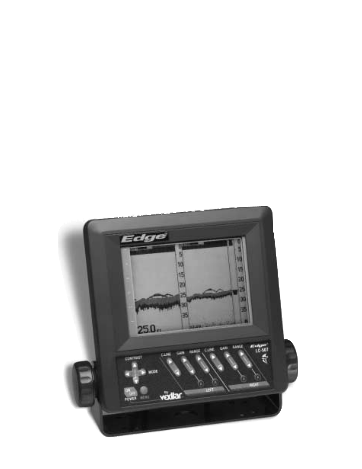
Edge LC-507 Operation Manual
2
General Description
The Edge 507 is like having two depth sounders in one. The features are designed to give the angler the best sonar for any situation. The split screen dual frequency design allows you to compar e
one view with the other to help you gain much more information
about what is below.
The dual frequency feature gives an you incredible advantage.
The Low frequency, 107 kHz, beam provides a wide cone with allot
of sensitivity. This allows you to see fish, as true arcs, as they pass
under the boat. Also, it allows you to see br eaks and structur e of f to
the sides of you. The high frequency beam, 400 kHz, is an excellent
compliment. It gives you a precise narrow beam for locating fish
and sharp edges of structure that are dir ectly under the boat. Using

3
these two beams together will allow you to locate fish, identify bottom conditions, and even control your boat better. Imagine following a weed line using the Edge. Simply keep the weeds within the
wide beam, but outside the narrow beam.
The Edge is very easy to use. All of the important control features are right on the front panel. Range, gain, auto/manual, and
clean line controls are only one button away. There are even separate controls for each screen.With three feature presets you can quickly add or change any of the features to meet the new conditions.
Imagine fishing with preset #1, with all features set for slow tr olling
along a sharp break. Then you decide to move to a new spot. Hit
the preset button to move you to the next feature setup, #2, that you
have programmed for high speed operation (super fast sweep and
higher gain). Now, down the lake you have found something interesting. Move to the next feature setup, #3, that you have programmed
for intense structure and fish finding (slower sweep speed, multiple echo view, fish alarm, and hard bottom alarm). Want your original settings back? Hit the preset button to get you back to setup #1
again. Internal memory backup insures that all feature selection will
be saved when the unit is shut off or disconnected from power.
The incredible features of the Edge ar e br ought to life by a beautifully detailed LCD. The 320 x 240 multi level pixel display is near
paper graph standards. Visibility on the brightest days and the darkest nights is unbelievable. The contrast control is right on the front
panel.
In addition to the innovative features, the Edge is a very high
quality device. It comes with the best warranty and product support in the industry. W ith 2 year warranty coverage and quality service and support you are sure to get the most out of the Edge. Got
a question or concern? One phone call is all it takes to quickly talk
to a technician who can help with anything you should need.

4
• Operating Voltage:
• Current Draw:
• Power Output:
• Frequency:
• Beam Angle:
• Resolution:
• Sounding Rate:
• Display Size:
• Dimensions:
• Weight:
10 - 16 Volts (12 Volts Nominal)
500mA (800 mA w/Backlight On)
1600 Watts (Peak to Peak) 200 Watts (RMS)
107 Khz & 400 Khz
38˚ & 10˚
320 x 240 Pixels
1800/Min. Maximum
5” x 3 1/2"
9.2"H x 8.9"W x 3"D
3.1 Lbs. (Unit Only)
SPECIFICATIONS
• Depth Ranges:
0-5', 0-10', 0-12’, 0-15', 0-20', 0-25’, 0-30', 0-35’, 0-40', 0-50', 0-60',
0-70’, 0-80’, 0-100’, 0-120', 0-150', 0-200'
LC-507 CONNECTIONS
5
INSTALLATION
You will need to find a place to mount the LC-507 that will make
it easy to view and reach. You must provide the unit with power
and mount the transducer and sensor assembly in an effective location.
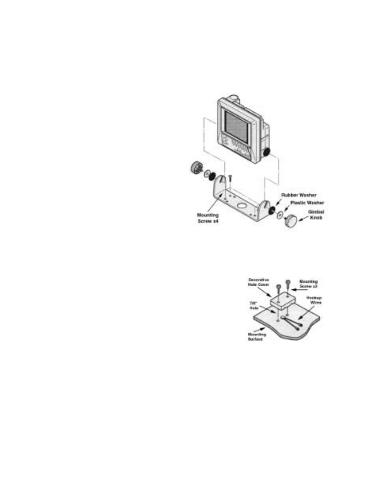
MOUNTING THE UNIT
Find a convenient place to
mount the unit. This may include
a boat seat, deck, dash, or a
portable case. Make sure that
there is plenty of room for the
unit to tilt freely without the
cables binding or stretching
behind the unit. Once you have
found the spot, remove the unit
from the gimbal bracket and
securely attach the bracket to the mounting surface. The screws pr ovided are for wood/carpet or dash mounting applications. An
optional removable swivel bracket is available. See page 32.
Note - ADecorative Wire Cover has been
included to help make your rigging job look
good. Use this to cover up the large hole you’ll
need to drill to fit the connector through.
CONNECTING THE POWER
Plug the 2 pin connector into the back of the unit. Find the closest source of 12 volts and route the cord to it. Keep the cord away
from sharp metal edges and avoid tight places where the cor d may
get crushed. Connect the white wire to positive and the black wire
to negative. If the cord provided is not long enough, more can be
added. Use 18 gauge wire minimum. Install the included 2 amp inline fuse, placed in the positive line, as close to the power source as
possible, to protect against shorts in the wiring.
6
MOUNTING THE TRANSDUCERS
Before you mount the transducers, you need to decide which
method is best for you and your boat. Your options are transom
mounted, in-hull mounted, trolling motor mounted, or portable.
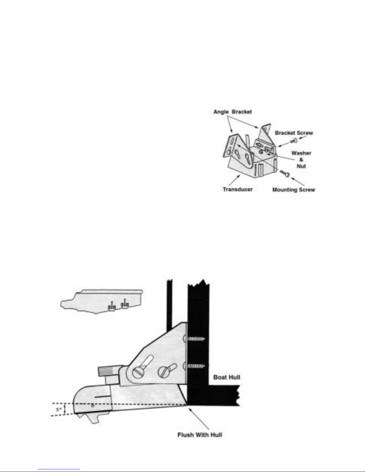
TRANSOM MOUNTING
Locate the transducers, and bracket
hardware. Each transducer has a mounting bracket assembly which includes;
2 Angle Brackets
4 Bracket Screws
4 Washers
4 Nuts
4 Mounting Screws
Attach the bracket to the transducer as shown in Figure 5. The
flanges of the bracket normally point outward, away from the transducer. If mounting space is tight, you can reverse the angle brackets and face the flanges inward.
Locate a spot
for each transducer similar to
the one in figure
6. Keep in mind
that you need
clear water flow
across the face of
the transducers
to insure a clear
reading at all
speeds. Stay
away from rivets,
ribs, or strakes
that would be
Figure 5
Figure 6
Figure 5

7
just in front of the transducers. They will disturb the water and
scramble the reading. The 107 kHz transducer is more susceptible
to this effect than the 400 kHz transducer, so it is a good idea to place
it closer to the center of the transom.
FOR EACH TRANSDUCER, FOLLOW THESE
INSTRUCTIONS TO OBTAIN A PROPER
INSTALLATION.
After you attach the mounting bracket to the transducer, hold it
up to the boat where you are planning to mount it (see figure 6).
Mark the four holes on the transom, or mounting plate, so that when
the bottom of the transducer is flush with the bottom of the boat the
holes are located at the bottom of the bracket slots. This gives you
room to "fine tune" the position of the transducer and optimize your
reading after you've put the boat back in the water. Drill out the
holes and install the transducer bracket assembly. T ighten the scr ews
down securely. Be sure to seal any holes drilled into the transom
with silicone to prevent water from leaking into the boat.
Route the transducer cord up to the unit taking the same care as
you did when you routed the power cord. Make sure that the cord
is restrained and not allowed to flop around in the wind. This can
cause stress on the wire inside the cable, and possible breakage. Plug
the transducer connector into the back of the unit and screw the
retaining ring down tight.
After you have put the boat back in the water confirm that you
can maintain a bottom reading at all boat speeds. If not, loosen the
bracket screws and tilt the transducer some more. Keep the front
edge flush with the boat, but drop the back edge down a little more.
If changing this angle several times does not clear up the reading,
loosen the mounting screws and slide the transducer down, slightly. Repeat these adjustments until you get a clear reading. Make sure
that all mounting screws are tight. Finally, fill any gap between the
transducer and the hull with silicone to prevent a rooster tail from
shooting up behind the boat.
8
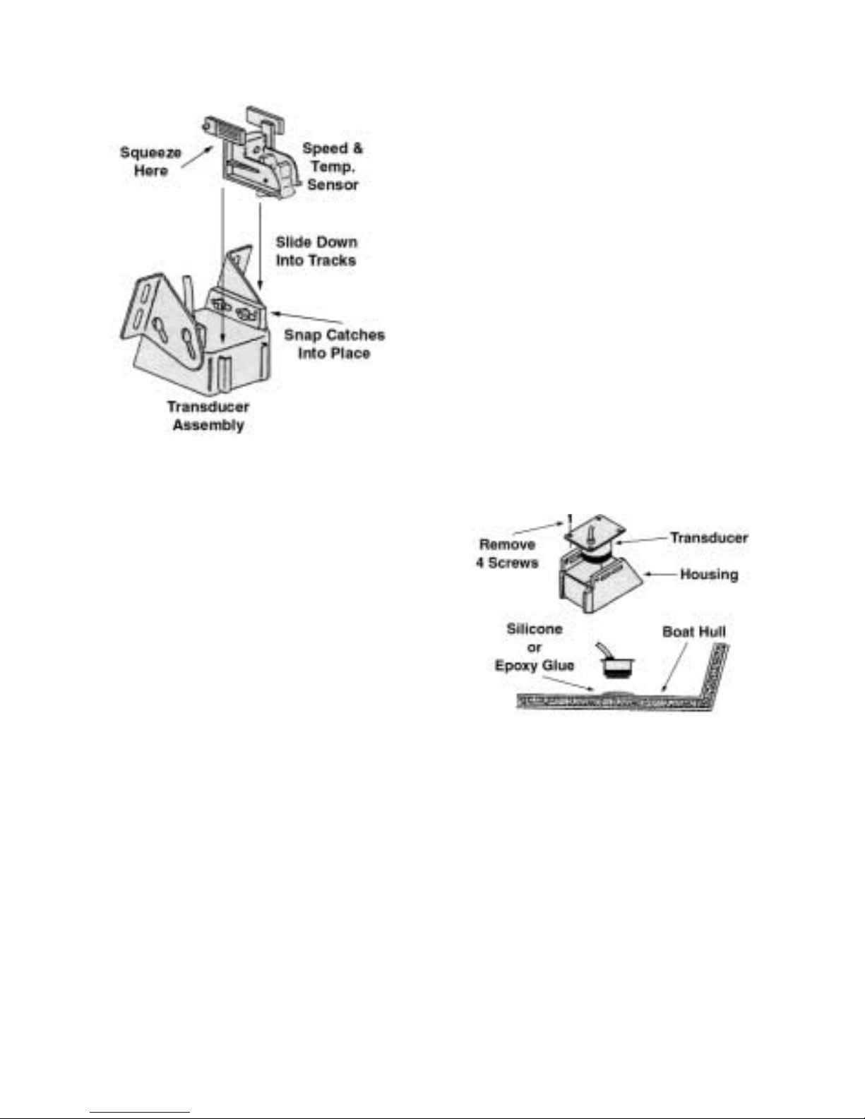
ATTACHING THE SENSOR
ASSEMBLY
The speed and temperature sensor assembly attaches to either transducer as shown. Pinch, or squeeze,
together the tabs at the top of the sensor and slide the assembly down into
the tracks on the back of the transducer. Push it down until it stops, and
then, push the tabs back, outward,
until the catches snap into the holes
on the transducer.
CAUTION - It is a good idea to
restrain the speed wheel from spinning
freely while trailering the boat. Damage may result because there is no
water to lubricate the wheel bearings. Arubber band works good for this.
IN-HULL MOUNTING
Finding the best location for the
transducers before mounting is critical. Choose a flat smooth spot near the
center of the bilge and near the back
of the boat. It is a good idea to make
a "test run" before you permanently
install each transducer. This makes sure that you can,
indeed, get a reading through your hull, and when the boat is on
plane. Put about a half inch of water in the bilge and hold the transducers in the intended location. Move the transducers around until
you get the best reading. Mark the spot.
Remove each transducer from its housing as shown in figure 8.
To install, clean the spot of mud and oil. Using an epoxy or silicone
glue, make a puddle about the same diameter as the transducer on
the hull. Place the transducer in the glue. Press it down firmly, gently twisting it back and forth, making sure that there ar e no air bubbles in the glue between the transducer and the hull. Let the glue
dry completely before turning the unit on.
Figure 7
Figure 8
9
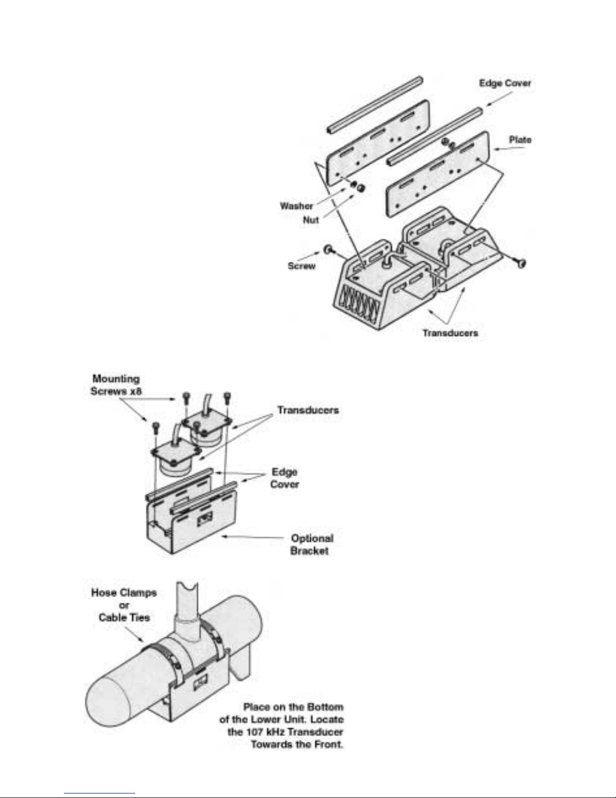
TROLLING MOTOR MOUNTING
Install the bracket assembly onto the transducers. Set
the two transducers down on
a flat surface, back to back.
Install the bracket assembly
as shown in figure 9. Use the
two included large cable ties
to attach the transducer to the
electric trolling motors lower
unit. Using the slots in the
transducer bracket, run the
ties through them and
around the motors lower
unit. Locate the transducers
on the bottom of the lower unit as in figure 10. Locate the 107 kHz
towards the front of the
motor. This transducer is
more susceptible to noise,
so keep it further away
from the propeller
Run the cables up the
shaft using smaller cable
ties to hold it in position.
Make sure that the cables
will not be damaged by the
movement of the trolling
motor. Plug the transducer
connectors into the back of
the unit and tighten the
retaining rings.
There is an optional one
piece mounting bracket,
part #TMB003. This bracket is more compact and
durable than the standard.
Figure 9
Figure 10
10
SENSOR MOUNTING
If you mount the transducers inside the hull of the boat or on an
electric trolling motor (described on page 8) you will need to use
the provided sensor mounting bracket, instead of the transducer, to
mount the speed and temperature sensor.
Snap the sensor assembly into the
mounting bracket as shown in figure 11.
Hold the assembly up to the boat at the bottom of the transom. Stay away from rivets,
ribs, or strakes that would be just in front of
the sensor, as they can affect your speed
reading. Mark the two holes on the transom, or mounting plate, so
that when the bottom of the sensor is flush with the bottom of the
boat the holes are located at the bottom of the bracket slots. The bottom of the speed wheel should be below the transom line.
Locate the two mounting screws and drill the appropriate sized
holes in the transom. Install the sensor assembly and tighten it down
securely. Don’t forget to seal the holes with silicone to prevent leakage.
CAUTION - It is a good idea to restrain the speed wheel from spinning freely while trailering the boat. Damage may result because ther e is
no water to lubricate the wheel bearings. Arubber band works good for
this.
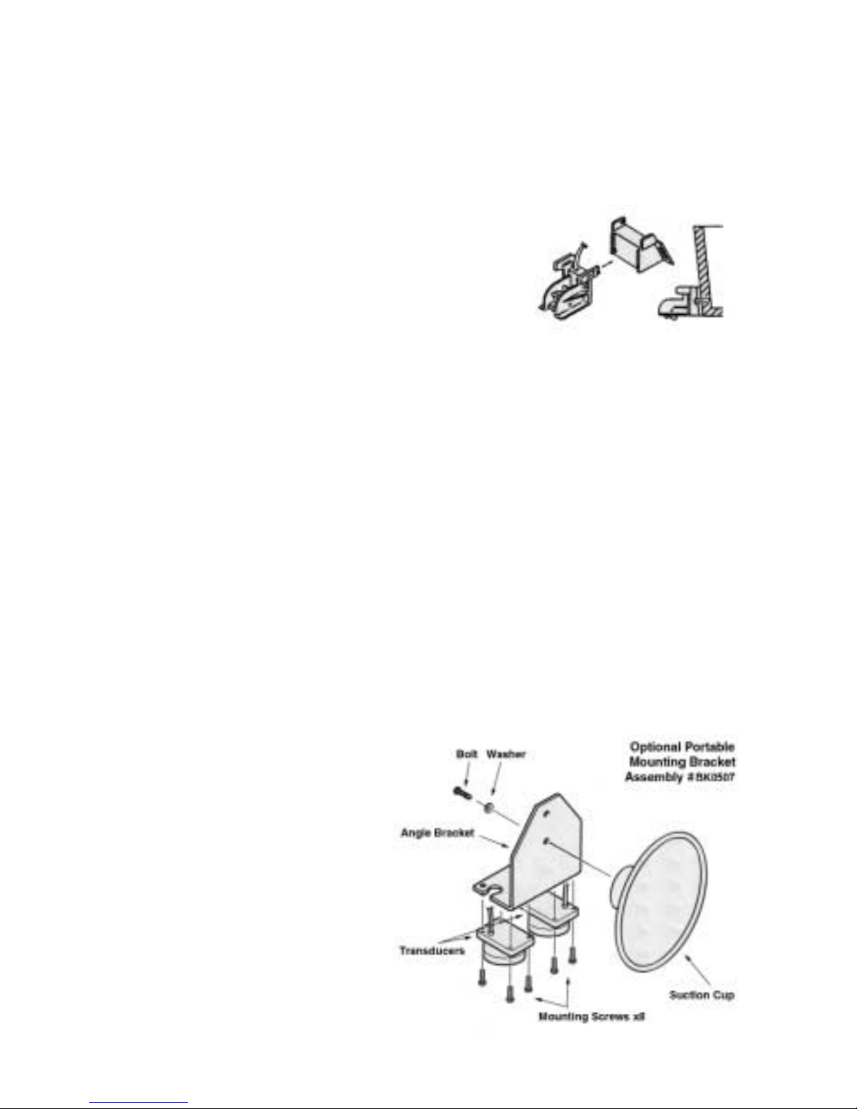
PORTABLE MOUNTING
An optional suction cup
bracket can be used to temporarily attach the transducers to the transom or side of
the boat. The cup should be
placed in a location where it
will not be torn off when the
boat goes high speed. The
optional BK0507 suction cup
mounting bracket works well
for this application.
Figure 11
Figure 12
11
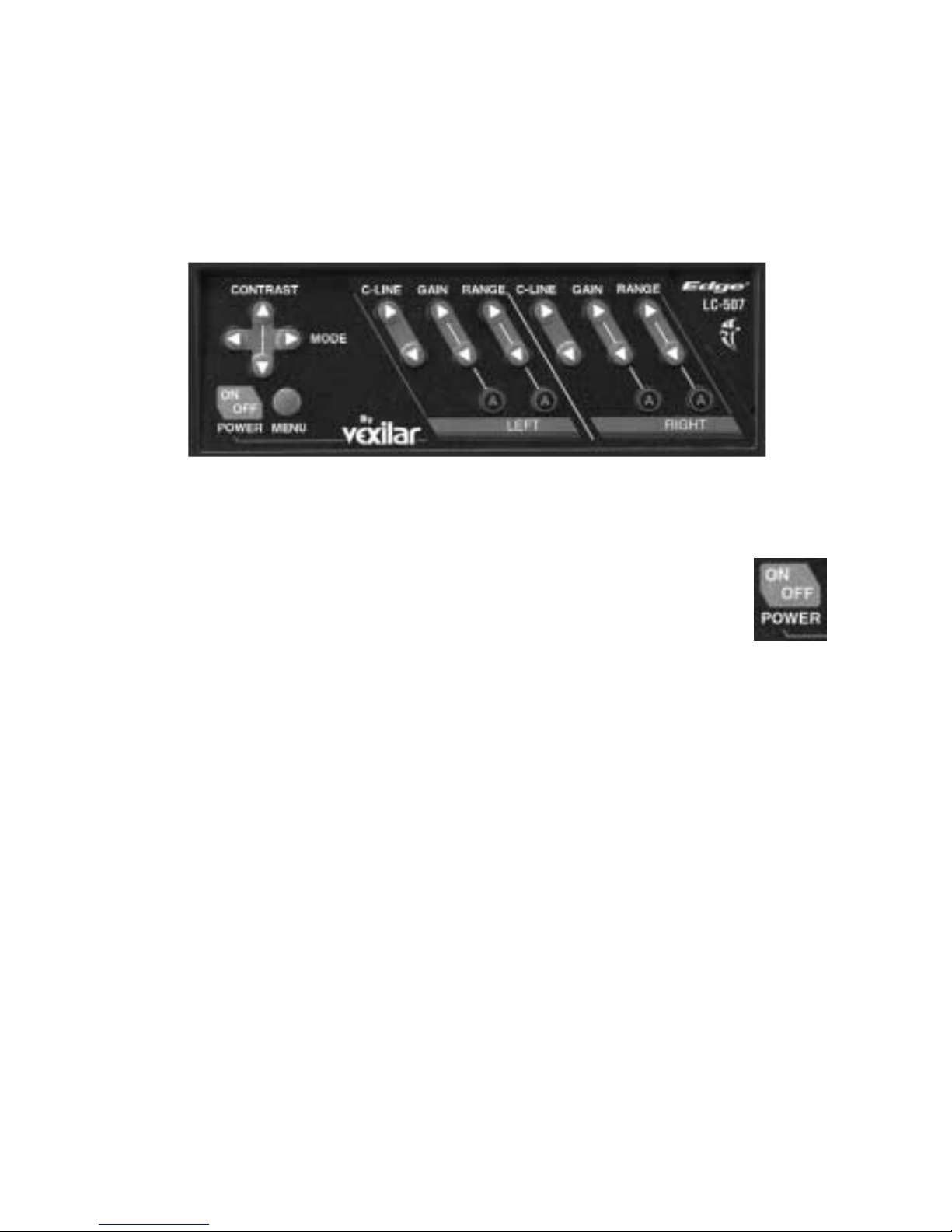
OPERATION
The LC-507 is a sophisticated depth sounder, yet very easy to
operate. All of the main sonar controls are right on the front panel.
There are even seperate contr ols for each beam. Figur e 13 shows the
control panel of the unit.
Figure 13
TURNING THE UNIT ON
Once the unit is connected to power you can turn it on.
Press the ON/OFF button. You will hear a series of short
beeps before the display shows up. To turn the unit off, press
this button again. All of your feature and menu settings will automatically be saved in memory. When you turn the unit on again,
these settings will be restored.
USING THE BUILT-IN SIMULATOR
When learning the operation of the unit, it may be helpful to activate the internal simulator. This will play a short program, on the
display, that will simulate a real world situation. You can experiment with all of the panel controls and menu functions and see the
results on the display.
To turn the simulator on, first make sure the unit is off. Now,
press the ON/OFF button and hold it in. You will hear the normal
series of beeps, followed by up to three more sets of beeps, about
three seconds later. Release the button after the last beep and the
simulator will start. There are three different programs. Each time
you start the simulator, a different program will start.
 Loading...