

Page 1
1
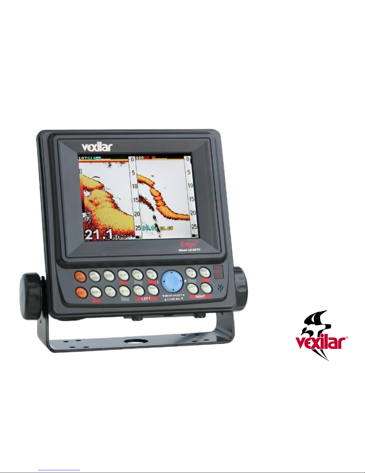
Edge
3
Color LCD
Depth Sounder
Model LC-507C
Owner’s Manual
Page 2

2
CONTENTS INTRODUCTION
The Concept
The whole idea of the Edge3 is the
ability to see the same thing using two
different types of sonar. The Edge3 is
actually two depth sounders built into
one unit. Each sounder has it’s own
advantages. The goal is to give you
the best of both worlds so that you can
know more about what’s underneath your boat.
TRUE Dual Frequency / Dual Beam Operation
The Edge3 is not your run-of-the-mill dual frequency depth
sounder. You truly have two separate sounders with two
separate transducers with separate controls.
107 kHz Depth Sounder
The first of the two sounders uses a 107 kHz frequency with
a 38° cone angle. This low frequency gives you a lot of power
throughout the very wide cone. Low frequencies have an
edge over higher frequencies by being able to cover a lot of
area and reach into deep water much more efficiently. Lower
frequencies also tend to filter out targets of very small size.
400 kHz Depth Sounder
The other half of the Edge3 uses a 400 kHz frequency offering
a 10° cone angle. This high frequency gives a very tight cone
for amazing precision. Higher frequencies have an advantage over lower frequencies for these reasons. Higher frequencies will also see small targets the low frequencies miss.
Introduction 2
Specs & Features 3
Installation 4
Connecting to Power 4
Transom Transducer Installation 4
Electric Trolling Motor Transducer Installation 5
In-Hull Transducer Installation 6
Temperature Probe Installation 6
Unit Operation 7
Understanding the Display 7
Control Panel Keys 9
Menu Functions 10
Accessories & Replacement Parts 15
Trouble Shooting 16
Service 16
Vexilar reserves the right to modify the features
and specification described within this manual
at any time and without notice.
Page 3
3
Separate Controls to Fine-Tune Each View
Because the two sounders act so differently, separate controls allow
you to make each show you what you want to see. For example,
you would generally keep the gain much lower on the 107 than
the 400 in the same depth of water. Also, you may be very interested in bottom content, yet at the same time want to see the entire
water column with the best view. With separate controls, you can
set the range on the 107 to best show bottom content and multiple
echoes while keeping the 400 set to show from the bottom up.
Ease of Use
The biggest problem with most high-end sounders these days
is the complexity of the controls and menus. The Edge3 reduces
this problem significantly by giving you front panel controls for
the most important functions, plus Modes that let you set up the
system for different situations. These Modes save your front panel
and menu settings. When you hit the Mode button to change to a
new Mode, your setting for the last Mode are saved. A common
practice is to set up your modes the way you want, and from then
on, simply turn the unit on and switch between your Modes.
SPECS & FEATURES
Display: 16-Color 320 x 240 TFT (4-3/4” x 3-3/4”)
Frequency: 107 kHz & 400 kHz
Cone Angle: 38° (107 kHz) & 10° (400 kHz)
Resolution: 2” Minimum
Power: 1600 Watts of Peak-to-Peak Power
Speed: 40 Pixel/Second Max
Voltage Requirement: 11 - 35 Vdc
Current Draw: 1.25 Amps Max
Size: 9-1/4” W x 8-1/2” H x 3-3/8” D
Weight: 3-3/4 Lbs
Features
• 4 User Modes
• “Favorite Feature” Key
• “Instant High-Speed” Key
• “Previous View” Memory
• Front Panel Auto/Manual Range
• Front Panel Auto/Manual Gain
• Front Panel Clean Line Control
• 107 & 400 Composite Feature
• 4 Optional Background Colors
• 6 Optional Signal Color Schemes
• x2, x4, or x8 Split Screen Zoom
• Auto or Selectable Zoom Zone
• Bottom Hardness Graph
• Selectable Pulse Length
• Selectable STC
• Multiple Echo Control
• Auto-Gain Level Control
• Fish Alarm
• Hard Bottom Alarm
• Temperature Probe
• Voltage Indication
• Clean Line
• Temp Zone Alarm
• Super-Bright Backlight
• 2-Year Warranty
Depth Ranges
2’, 3’, 5’, 7’, 10’, 15’, 20’,
25’, 30’, 35’, 40’, 50’, 60’,
70’, 80’, 100’, 120’, 150’,
and 200’
Page 4
4
INSTALLATION
You will need to find a place to mount the unit that will make it
easy to view and reach. You must provide the unit with power
and mount the transducer and temp sensor in an effective location.
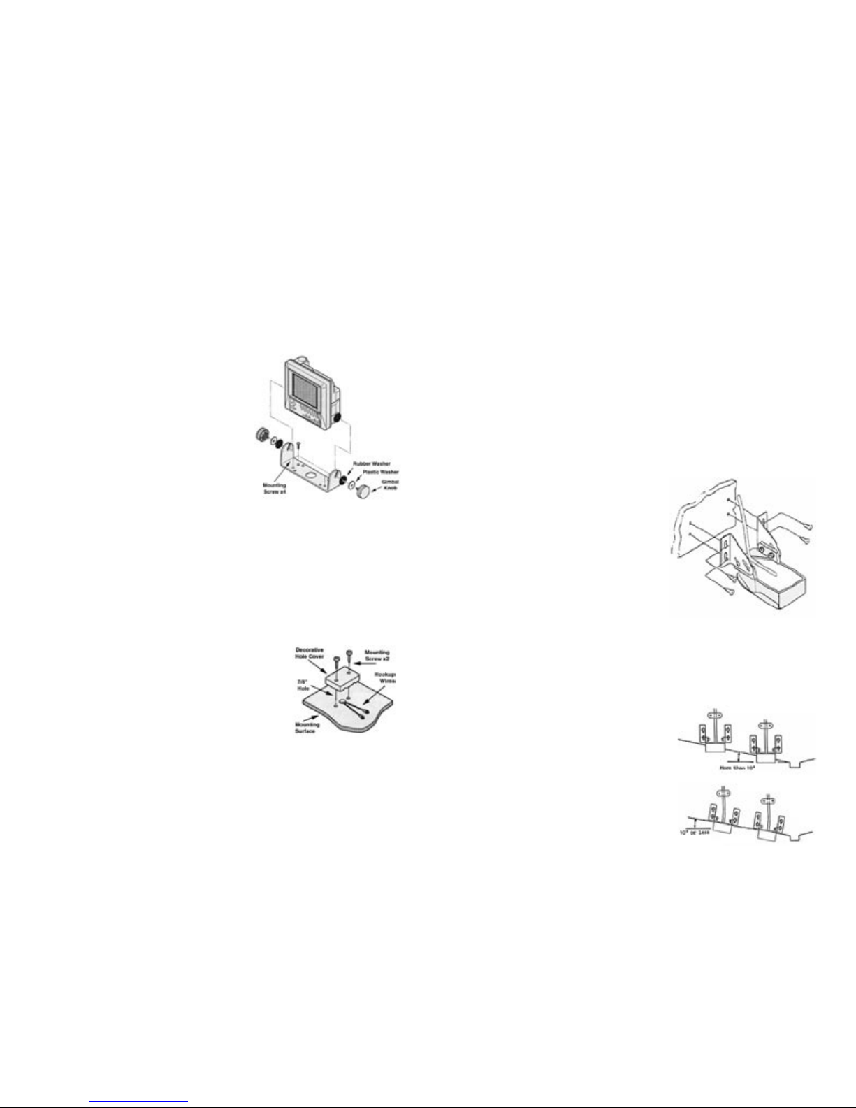
Mounting the Unit
Find a convenient place to mount
the unit. Make sure that there is
plenty of room for the unit to tilt
freely without the cables binding or
stretching behind the unit. Once you
have found the spot, remove the unit
from the gimbal bracket and securely
attach the bracket to the mounting surface. The screws provided
are for wood/carpet or dash mounting applications. If you want
to use an optional removable swivel bracket, be sure it’s able to
support the weight of this unit.
A Decorative Wire Cover has been included to help make your
rigging job look good. Use this to cover up the large hole you’ll
need to drill to fit the transducer, temperature probe, and power
connectors through.
Connecting the Power
Plug the 2 pin connector into the back of
the unit. Find the closest source of 12 volts
and route the cord to it. Keep the cord
away from sharp metal edges and avoid
tight places where the cord may get crushed. Connect the white
wire to positive and the black wire to negative. If the cord provided is not long enough, more can be added. Use 18 gauge wire
minimum. Install a 2 amp in-line fuse, placed in the positive line,
as close to the power source as possible, to protect against shorts
in the wiring.
MOUNTING THE TRANSDUCERS
The transducer mounting method will depend on which version
of the Edge3 you purchased. In either version, it is important to
mount the two transducers as close together as you can. This
will insure your Edge3 gives you the information it was design
to offer.
• LC-507C TM - Transom Mount Transducers
• LC-507C ETM - Trolling Motor Mounted Transducers
• LC-507C IH - In-Hull Mounted Transducers
Transom Mounting
Locate the transducers and bracket
hardware. Each transducer has a
mounting bracket assembly which
includes;
2 Angle Brackets
4 Bracket Screws
4 Washers
4 Nuts
4 Mounting Screws
Attach the bracket to the transducer as shown in Figure 5. The
flanges of the bracket normally point outward, away from the
transducer. If mounting space is tight, you can reverse the angle
brackets and face the flanges inward.
Locate a spot for each transducer similar to the one shown. If your boat hull
has a significant rise (more than 10°),
you should mount the transducer so the
bottoms are parallel to the water line.
If your boat hull is level, or has only a
small rise, you should keep the bottom
of the transducers parallel with the hull
Page 5
5
line. Keep in mind that you need clear water flow across the face
of the transducers to insure a clear reading at all speeds. Stay
away from rivets, ribs, or strakes that would be just in front of
the transducers. They will disturb the water and scramble the
reading. The 107 kHz transducer is more susceptible to this effect
than the 400 kHz transducer, so it is a good idea to place it closer
to the center of the transom where smooth water flow is easier to
maintain.
After you attach each mounting bracket to each transducer, hold
it up to the boat where you are planning to mount it. Mark the
four holes on the transom, or mounting plate, so that when the
bottom of the transducer is flush with the bottom of the boat the
holes are located at the bottom of the bracket slots. This gives
you room to "fine tune" the position of the transducer downward
and optimize your reading after you've put the boat back in
the water. Drill out the holes and install the transducer bracket
assembly. Tighten the screws down securely. Be sure to seal any
holes drilled into the transom with silicone to prevent water from
leaking into the boat.
Route the transducer cord up to the unit taking the same care as
you did when you routed the power cord. Make sure that the
cord is restrained and not allowed to flop around in the wind.
This can cause stress on the wire inside the cable, and possible
breakage. Plug the transducer connector into the back of the unit
and screw the retaining ring down tight. Make sure the frequency
labeled on the transducer cable matches the frequency labeled on
the transducer jack on the unit. If you get the two transducer connections reversed, the until will not operate properly.
After you have put the boat back in the water confirm that you
can maintain a bottom reading at all boat speeds. If not, loosen
the bracket screws and tilt the transducer some more. Keep the
front edge flush with the boat, but drop the back edge down a
little more. If changing this angle several times does not clear up
the reading, loosen the mounting screws and slide the transducer
down slightly. Repeat these adjustments until you get a clear
reading. You’ll most likely be looking for a balance between high
speed performance and the transducers producing a “rooster
tail”. The further you go down below the hull, the better the
transducer will perform at high speed, but the more likely it will
be to result in water spray. Make sure that all mounting screws
are tight when you’re done adjusting.
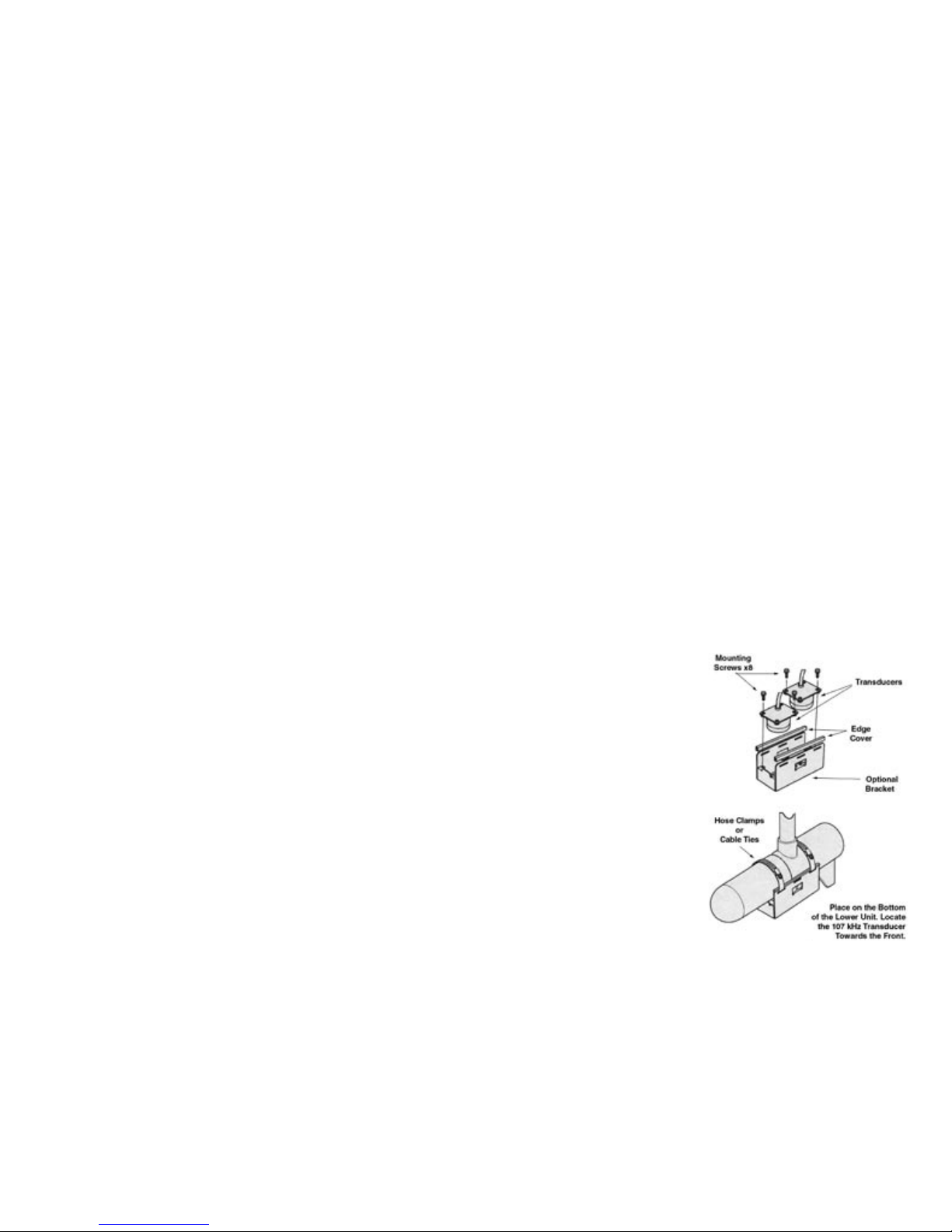
Trolling Motor Mounting
Install the transducers into the one-piece trolling motor mounting bracket as shown. Use the two included large cable ties to
attach the transducer to the electric trolling motors lower unit.
Using the slots in the transducer bracket, run the ties through
them and around the motors lower unit. Locate the transducers
on the bottom of the lower unit as shown. Locate the 107 kHz
towards the front of the motor. This transducer is more susceptible to turbulence, so keep it further away from the propeller.
Run the cables up the shaft using
smaller cable ties or electrical
tape to hold it them in position.
Make sure that the cables will
not be damaged by the movement of the trolling motor. Plug
the transducer connectors into
the back of the unit and tighten
the retaining rings. Make sure
the frequency label on the
transducer cable matched the
frequency labeled on the transducer jack on the unit. If you get
the two transducer connections
reversed, the until will not operate properly.
Page 6

6
towel or dry cloth to finish the clean-up of
the areas. Let dry for a few minutes.
Place the transducers exactly where you
want to install them. Apply four supplied
positioning pads around each transducer.
The positioning pads are needed to prevent
your transducers from drifting off the target
area while the A.C.E. adhesive sets up.
Use one packet of A.C.E. for each transducer and attach one
transducer at a time. Follow the mixing directions on the packet
of A.C.E. Adhesive and apply the entire packet directly to the face
of one transducer. Place the transducer into position. Press firmly
and twist slightly back-and-forth to work-out any air bubbles
that might have been trapped in the epoxy.
IMPORTANT: Do not power-up your Edge for at least 12 hours.
Doing so will effect adhesive curing, allowing air pocket to form
between the transducers and the hull. This will ruin your installation efforts.
Installing the Temperature Probe
Install the temperature probe in a suitable location. If you install
it on the transom of your boat, use the two screws provided to
attach it to your transom or transom mounting plate. Be sure not
to mount it so it extends below the bottom of the hull. It only
needs to be below the water
line to function properly.
If you install it on your
electric trolling motor, use a
small cable tie to secure it to
the trolling motor bracket as
shown.
In-Hull Mounting
Finding the best location for the transducers before mounting is
critical. Choose a flat smooth spot near the center of the bilge
and near the back of the boat. It is a good idea to make a "test
run" before you permanently install each transducer. This makes
sure that you can, indeed, get a reading through your hull, and
when the boat is on plane. Put about a half inch of water in the
bilge and hold the transducers in the intended location. Move
the transducers around until you get the best reading. Mark the
spot.
Surface preparation and location are the keys to having a good
sonar transducer installation that will last for years, so please
take a few extra minutes to prepare the surface area. Also, the
temperature should be at least 60º F while performing the installation.
Select an area inside your boat to mount each transducer. Try to
keep the two transducers as close together as you can. Ideally, for
reliable high speed operation, you will need to place the transducers near the center of the transom area of the boat, which is
often near the drain plug. You must attach each transducer to a
solid hull area, this means you cannot have a double hull aluminum or a foam layer in the fiberglass between the transducers
and the water.
It is critical you find a smooth, flat spot to place your transducers.
Small ridges, bumps or even paint under a transducer will affect
the quality of the sonar signal. Your Edge comes with two surface
preparation kits, each including a Scotch-Bright® pad to smooth
any rough areas and to help get you down to the base material
for a secure install.
Use the supplied cleaning patches of Isopropyl Alcohol to remove
dust and dirt from the target areas you are mounting to. Be sure
to also wipe clean the faces of your transducers. Use a paper
Page 7

7
UNIT OPERATION
The Edge3 is designed to be powerful, yet extremely easy to operate. The first thing you’ll want to do is get familiar with the front
panel keys and their functions.
To help you learn how each feature works, the Edge3 has a builtin simulator. You can turn this feature on and then be able to try
out all of the controls and menu settings before you get on the
water.
REMEMBER: If you’ve just installed in-hull transducers
and the adhesive has not fully dried, be sure to unplug the
transducers from the unit before you turn it on.
Turning the Unit On
To turn the Edge3 on, press and hold the ON key until you hear
the start-up tone. It will take a second or two to boot before you
see the display light up.
Turning the Unit Off
To turn the Edge3 off, press and hold the OFF key.
Activating the Simulator
To active the simulator mode:
1. Turn the unit on.
2. Press the MENU key three times.
3. Press the key once or the key until the cursor reaches
the Simulator setting.
4. Press the key to highlight ON.
5. Press the USER/CLR key to exit the menu.
UNDERSTANDING THE DISPLAY
In most situations, the Edge3’s display will be set up in the split
screen mode with the 107 kHz beam on one side and the 400 kHz
beam on the other. Scattered around the display are some items
offering information. Refer to the figure on the next page and the
following explanations to help you understand what the different items on the Edge3 display indicate.
Beam Frequency - Indicates the operating frequency of the beam
for each screen. If the system is set to only show one beam, the
frequency of it will show on the far left.
Beam Gain Level - Indicates the level of the gain by both a digital
number and a bar graph.
Auto - Indicates that the Auto Range (R) or Auto Gain (G) control
is on. If no letter shows, it indicates the unit is in manual range
or gain mode.
Current Range Scale - Indicates the currently selected range for
each beam. The number at the bottom of the column shows the
maximum depth the unit can read when set to this range.
Water Surface Temperature - Indicates the temperature of the
water as reported by the temperature probe.
Battery Voltage - Indicates the voltage of the power supply that
is providing power to the Edge3.
Clean Line Level - Indicates the level of the Clean Line feature
for each beam.
Water Depth - Indicates the depth of water. In split screen mode,
this number is determined by the right beam.
Page 8

8
Gain & Range
Right Beam Controls
Gain & Range
Left Beam Controls
Beam Frequency Beam Gain Level
Water Depth
(Determined by Right
Screen)
Weak
Strong
Current Mode
Power On
&
History Memory
Power
Off
Instant High-Speed Mode
Clean Line Level
(Right Beam)
Red Lens
(No Function)
Alarm Speaker
Beam Select for Clean Line Control
Clean Line Level Control
&
Menu Cursor Navigation Keys
Clean Line Level
(Left Beam)
Signal Strength Key
Menu
Auto Range
Auto Gain
Mode
Favorite Feature
Key & Menu Exit
Battery Voltage
Water Surface
Temperature
Beam Frequency
Beam Gain Level
Left Beam
Right Beam
Current Range Scale
Left Beam
Right Beam
OPERATION
Auto
Auto
Page 9

9
Current Mode - Shows the currently active mode (1 - 4)
Signal Strength Key - Shows the color verses signal strength for
the selected color scheme. The stronger colors are represented
towards the top of the key and the weaker color towards the
bottom. The upper most color is the Clean Line color.
CONTROL PANEL KEYS
ON / MEMO - Push and hold to turn the unit on.
When the unit is on, push to activate the Memory Mode. Push
the and buttons to review the last X screens of history. Push
again to exit the Memory Mode.
OFF - Push and hold to turn the unit off.
HS MODE - Push to enter the Instant High Speed Mode. The
unit will shift to its maximum speed of 40 pixels per second.
Auto Range and Auto Gain features are disabled in this mode.
MENU - Push to enter the Edge3’s menu. Push repeatedly to
change to subsequent menu pages.
MODE - Push to change to the next Mode. Selections entered
for the current Mode will be saved.
USER / CLR - Push to activate the configured “Favorite Feature”.
A small menu item will appear in the upper left part of the display. Press again to change the menu setting or use the and
keys to change the current setting. The small menu will automatically exit three seconds after the last key is pressed. See the
section on Menu Settings to learn how to configure this key.
When in Menu Mode, press this key to exit (clear) the menu.
A / R - Push to toggle on and off the Automatic Range Control
feature. When Auto-Range is on, an “R” will show at the top of
each beam display. The Auto-Range features maintains the best
view of the bottom, according to the A-RNG-MODE menu setting for each beam.
When this feature is off, you will need to manually change the
range setting using the RANGE + and RANGE — keys to keep
the bottom in view over various water depth changes.
A / G - Push to toggle on and off the Automatic Gain Control
feature. When Auto-Gain is on, a “G” will show at the top of each
beam display. The Auto-Gain feature tries to maintain the optimum gain level for the current depth, according to the A-GAINLEVEL menu setting for each beam.
When this feature is off, you will need to manually change the
gain setting using the GAIN + and GAIN — keys to maintain the
preferred gain level.
GAIN + - Push to increase the gain level. When in Auto-Gain
mode, you can temporarily increase the level, but the auto feature
will readjust it again.
GAIN — - Push to decrease the gain level. When in Auto-Gain
mode, you can temporarily decrease the level, but the auto feature will readjust it again.
In split-screen mode, you have a set of range and gain keys for
each beam. When in full-screen mode, either set of keys will control the full-screen beam.
BEAM SELECT / C-LINE ADJ - The large round blue control is
used to select the beam and then adjust its Clean Line level. The
currently selected beam is indicated by a red colored gain level
indicator. Press the or keys to change the selected beam,
then press the or keys to adjust the Clean Line level.
Page 10

10
The BEAM SELECT / C-LINE ADJ control also is used for
navigation within the Edge3’s menus.
UNDERSTANDING THE MENU
Press the Menu key to enter the first menu page, MENU 1. To
change to the next menu press MENU again. You can exit any
menu by pressing the USER/CLR key, or any other white key.
Setting the Favorite Feature Key
The Favorite Feature key (USER/CLR) is a handy way to quickly
access your most often adjusted menu item, by simply the press
of one key. You can set the menu item the key accesses to any
menu item available.
Once you’ve determined which feature you want to assign to the
Favorite Feature key, simply highlight it using the menu navigation keys. Then press and hold the USER/CLR key. You will
notice that the circle next to the menu item become filled with
blue as the unit beeps. This indicates that this menu item is set as
your Favorite Feature.
MENU 1
The settings on this menu affect all Modes.
BRIGHTNESS
This setting controls the brightness of the display. You have five
levels of brightness to chose from, dim to bright. The higher the
brightness, the easier the display is to see in bright conditions,
but more power is required.
To change the brightness press...
MENU --> or .
MENU 2
The settings on this menu affect each mode, so only the currently
active mode will retain the setting changes. Menu 2 is divided
into two section. The top portion controls the function for the
right beam, or those for full screen mode.
RIGHT
This setting controls the frequency of the beam for the right side
of the display, or the operating frequency for full screen mode.
To change the frequency press...
MENU --> MENU --> or .
SWEEP
This setting controls how fast the display moves across the screen,
and how fast the Edge3 transmits each pulse. There are five settings from Stopped to 4. For the most accurate representation of
what’s below you, choose a setting that as closely matches the
boat’s speed as you can.
To change the sweep speed for the right beam press...
MENU --> MENU --> --> or .
A-RNG-MODE
Automatic Range Mode controls how the Auto-Range feature
maintains the view of the bottom. It only applies when the AutoRange feature is on. 1ST configures the system to maintain the
best view of the bottom. 2ND configures the system to make
sure the range setting is adjusted deeper, so you can always see a
second bottom echo. 3RD insures the system will allow room for
a third echo.
To change the A-RANGE-MODE for the right beam press...
MENU --> MENU --> --> --> or .
Page 11

11
A-GAIN-LEVEL
Automatic Gain Level configures how the system controls the
gain level when the Auto-Gain feature is on. “L” keeps the gain
control on the lower side, “M” keeps it near the middle, and “H”
keep the gain high.
To change the A-GAIN-LEVEL for the right beam press...
MENU --> MENU--> --> -->
then or .
A-MODE
This setting places a vertical display at the right side of the beam
view which shows an “instantaneous” view of current information. It does not speed up the update rate of the unit, but it does
allow you to recognize changes more quickly than the normal
view, especially at lower sweep speeds.
To activate or disable A-Mode for the right beam press...
MENU --> MENU--> --> --> -->
then or .
FISH ALARM
The fish alarm will sound an audible alarm when the unit detects
an object that is not part of the bottom. You can set it to sound on
small “S” or only larger targets “L”.
To active or disable A-Mode for the right beam press...
MENU --> MENU--> --> --> --> -->
then or .
LEFT
This setting controls the frequency of the beam for the left side
of the display, or to activate full screen mode. Full screen mode
is activated when you select “N/A”. The frequency of the single
beam is determined by the RIGHT selection.
To change the frequency for the left beam press...
MENU --> MENU--> --> --> --> --> -->
then or .
SWEEP
This setting controls how fast the display moves across the screen,
and how fast the Edge3 transmits each pulse. There are five settings from Stopped to 4. For the most accurate representation of
what’s below you, choose a setting that as closely matches the
boat’s speed as you can.
To change the sweep speed for the left beam press...
MENU --> MENU--> --> --> --> -->
then or .
A-RNG-MODE
Automatic Range Mode controls how the Auto-Range feature
maintains the view of the bottom. It only applies when the AutoRange feature is on. 1ST configures the system to maintain the
best view of the bottom. 2ND configures the system to make
sure the range setting is adjusted deeper, so you can always see a
second bottom echo. 3RD insures the system will allow room for
a third echo.
To change the A-RANGE-MODE for the left beam press...
MENU --> MENU --> --> --> -->
then or .
Page 12

12
A-GAIN-LEVEL
Automatic Gain Level configures how the system controls the
gain level when the Auto-Gain feature is on. “L” keeps the gain
control on the lower side, “M” keeps it near the middle, and “H”
keep the gain high.
To change the A-GAIN-LEVEL for the left beam press...
MENU --> MENU--> --> -->
then or .
A-MODE
This setting places a vertical display at the right side of the beam
view which shows an “instantaneous” view of current information. It does not speed up the update rate of the unit, but it does
allow you to recognize changes more quickly than the normal
view, especially at lower sweep speeds.
To activate or disable A-Mode for the left beam press...
MENU --> MENU--> -->
then or .
HARD-BTM-ALM
The Hard Bottom Alarm will sound an audible alarm when the
unit detects a second echo. It will only function when the ARANGE-MODE feature for the left beam is set to 2ND or 3RD
To activate the Hard bottom Alarm press...
MENU --> MENU --> --> or .
MENU 3
Menu 3 controls items such as the display color, zoom, and the
temperature alarm. The settings on this menu affect all Modes.
BACK-GRD
This setting changes the color of the display’s background. Choose
a background color based on personal preference and visibility.
There are four choices; White, Light Blue, Black, and Dark Blue.
To change the background color press...
MENU --> MENU --> MENU --> or .
COLOR
The color setting allows you to change the color scheme for the 16
display colors. Each color represents a different strength return
signal. Choose a color scheme based on personal preference and
visibility. There are six choices.
To change the background color press...
MENU --> MENU --> MENU -->
then or .
ZOOM
Zoom magnifies the specified area of the right beam. It is useful
for detecting targets that are very close to the bottom or that are
very close together in deeper water. There are two forms of zoom;
Auto maintains a zoomed view of the bottom, and Manual maintains a zoomed view of an area you specify. The zoomed beam
is determined by the right beam. The left beam will no longer be
visible when zoom is activated.
To active the zoom mode press...
MENU --> MENU --> MENU --> -->
then or .
Page 13

13
Adjusting the Manual Zoom
To adjust the manual “zoom zone”, exit the menu and then use
the RANGE + and RANGE — keys for the left beam on the front
panel. You will notice a green bar on the right side of the right
beam moves as you make adjustments. Align the green bar with
the area you want to magnify. This indicates the area that will
appear zoomed on the left side of the display.
ZOOM-RATE
The zoom rate determines the amount of magnification. You have
magnification choices of x2, x4, and x8. For flatter bottoms, you
can choose x8. For greatly undulating bottoms, use x2.
To change the zoom rate press...
MENU --> MENU --> MENU --> --> -->
then or .
HARD-BTM-LEVEL
This setting turns on and off the hard bottom level indicator and
graph. When activated, a pink colored graphical display is added
below the right beam, or entire beam in full screen mode. In addition, a large pink digital number is also added in the upper left
corner of the display. The number will vary from 0 to 20, depending on the hardness of the bottom. The graph will show changes
over time and corresponds to the bottom display. This allows you
to easily see where the bottom content changes.
To activate or disable Hard Bottom Level press...
MENU --> MENU --> MENU --> --> --> -->
then or .
COMPOSITE
Composite mode places the 107 kHz beam and the 400 kHz beam
on top of each other. Objects that are only visible with the 107
kHz beam are represented by a gray scale color scheme. Objects
only visible with the 400 kHz beam are represented by a green
color. Objects visible with both beams are colored red. In order
to activate the Composite mode, you must first be in split screen
mode.
To activate or disable Composite mode press...
MENU --> MENU --> MENU --> --> -->
then or .
TEMP-ALARM
The temperature alarm gives you the ability to sound an audible
alarm when the water surface temperature falls within a specified zone or outside a specified zone.
To enter the Temp Alarm sub-menu press...
MENU --> MENU --> MENU --> -->
then .
To activate the alarm press once for the “In-Range” alarm
and twice for the “Out-Range” alarm.
To turn the Temperature Alarm off, press repeatedly until
OFF is displayed.
To adjust TEMP-SET-1 (the lower temp value) press
then or to adjust the value.
To adjust TEMP-SET-2 (the upper temp value) press -->
then or to adjust the value.
Press the MENU key to exit the Temp Alarm sub-menu.
Page 14

14
MENU 4
The forth and final menu contains controls for some basic functions and unit of measure settings.
SUPER RANGE
Super Range controls the way the display appears when the
depth range changes. When Super Range is OFF, and the range
changes, you will see the point at which the range changed on the
display. This point will scroll across the screen until it disappears
at the far left side. When Super Range is ON, there will be no
visible point at which the depth changed. Super Range adjusts
the entire display to the new range.
To activate or disable the Super Range feature press...
MENU --> MENU --> MENU --> MENU (HOLD)
then or .
PULSE-LENGTH
Pulse Length controls how long each “ping” of the transducer is.
Longer pulse lengths allow better deep water performance but
reduce resolution. Shorter pulse lengths give the best resolution,
but have problems reaching into deep water.
To change the Pulse Length press...
MENU --> MENU --> MENU --> MENU (HOLD)
then and then or .
STC
STC stands for Surface Time Control. Its function is to reduce the
surface clutter normally found in the first few feet of the water
column by reducing the gain in this region.
To activate or disable STC press...
MENU --> MENU --> MENU --> MENU (HOLD)
then --> and then or .
DEPTH
The Depth feature controls how the digital depth number appears
at the bottom of the display. Your choices are OFF, S (Small), or
L (Large). OFF turns off the digital depth and all other digital
indications. Small displays the digital depth and other indicators.
Large makes the digital depth appear larger and easier to read.
The other indicators stay the same size.
To change the Depth setting press...
MENU --> MENU --> MENU --> MENU (HOLD)
then --> --> and then or .
DEPTH-UNIT
This feature lets you choose between Meters and Feet for depth
measurement.
To change the Depth-Unit setting press...
MENU --> MENU --> MENU --> MENU (HOLD)
then --> --> -->
and then or .
TEMP-UNIT
This feature lets you choose between Celsius and Fahrenheit.
To change the Depth-Unit setting press...
MENU --> MENU --> MENU --> MENU (HOLD)
then --> --> -->
and then or .
Page 15

15
TEMP-ADJ
This feature allows you to calibrate the temperature reading, if
necessary.
To modify the temperature reading press...
MENU --> MENU --> MENU --> MENU (HOLD)
then --> -->
and then or .
VOLT-ADJ
This feature allows you to calibrate the voltage reading, if necessary.
To modify the temperature reading press...
MENU --> MENU --> MENU --> MENU (HOLD)
then -->
and then or .
SYSTEM-RESET
System Reset will revert all settings back to the factory originals.
This can be handy for trouble shooting erratic operation or simply
getting the setting back to a known state.
To perform a System Reset press...
MENU --> MENU --> MENU --> MENU (HOLD)
then --> --> .
System Reset will cause the lose of all modified settings.
ACCESSORIES & REPLACEMENT PARTS
Depth
TBX071 107 kHz Transducer $79.00
TBX072 400 kHz Transducer $79.00
CB0001 10’ Transducer Extension Cable $24.00
CB0002 20’ Transducer Extension Cable $29.00
HSB003 Transducer Transom Bracket $5.00
TBH001 Transducer Transom Housing $3.00
BKT003 One-Piece Transducer ETM Bracket $18.00
ACE001 A.C.E. Transducer Adhesive $8.00
Temperature
TPX002 Temperature Probe $39.00
CB0003 10’ Temp Probe Extension Cable $35.00
Mounting
GBX003 Unit Gimbal Bracket $20.00
GKX003 Gimbal Bracket Knob $2.30
PCX002 Power Cord with Fuse $16.00
Switch Boxes
SB-100* Switch Box - 2 transducers on 1 unit $45.00
SB-200* Switch Box - 2 units on 1 transducer $45.00
*You need one switch box for each beam.
Prices subject to change without notice
Page 16

16
Possible Cause
TROUBLE SHOOTING
Unit is turned on, but there is
no display.
Contrast is adjusted too low.
Increase contrast.
Unit will not turn on.
Check for proper battery polarity
and that you have fully charged,
working batteries.
Unit runs well for a short time,
then the unit quits.
Bad battery or poor connection.
Check voltage level under load
and all electrical connections.
Unit runs and shows display
light, but does not read depth.
Transducer is not plugged in or
not in contact with the water.
Unit works, but needs high gain
to see bottom or targets.
Transducer is not aimed correctly or needs to be cleaned.
Unit works, but has too many
lines on the display. Can't tell
what is what.
Many air bubbles or very small
targets in the water. Electrical
noise from another device.
Unit works well when sitting
still or at slow trolling speeds,
but loses reading when the boat
speeds up.
Improper transducer installation or adjustment. Loss of
clear water flow across the face
of the transducer when the boat
reaches a certain speed.
Unit works, but shows noise
when the engine is started or the
electric trolling motor is turned
on.
Improper ground or missing
ground in electrical system.
Defective engine or trolling
motor.
Temperature does not show or
is not accurate.
Temp sensor is not plugged in
or is not in the water.
Symptom
If this trouble shooting guide does not help, please contact our
customer service department.
SERVICE AND SUPPORT
If you find that you need help, feel free to contact us. Please have
ready the model number and, if possible, the serial number of
your product. Be sure to read the Trouble Shooting sections first.
Address
Vexilar, Inc.
6667 W Old Shakopee Road
Minneapolis, MN, 55438
Telephone
(952) 884-5291 (8 am to 5 pm M-F Central Time)
Fax
(952) 884-5292
Web Site
www.vexilar.com
Email
service@vexilar.com
 Loading...