

Page 1

1
CONTENTS
General Description 2
Specifications 3
Gimbal Unit Assembly and Installation 4
Portable Unit Assembly and Installation 10
Operation 14
Menu Functions 16
Using the Zoom modes 19
Understanding the Colors 20
Typical Indications 21
Frequently Asked Questions 24
Maintenance 25
Troubleshooting 26
Other Vexilar Products 27
Optional Transducers 30
Service and Support 32
Founded in 1960, Vexilar, Inc. has a long
history of bringing revolutionary
technology to the sport fishing industry.
Some of the Vexilar firsts include: the first
liquid crystal display, the first fish alarm,
the first three color display, the first CRT and straight line
paper graphs, and the first split-screen zoom flasher for the
sport fisherman.
CLC-200 Operation Manual
Page 2
2
GENERAL DESCRIPTION
The five-color CLC-200 is a compact and light-weight
liquid crystal depth sounder. It indicates depth, shows
changes in bottom content, and conditions. It can also
discriminate between large underwater targets, such as
fish, and smaller targets such as bait fish and plankton.
The unit transmits bursts of high frequency pulses which
are converted from electrical to mechanical energy by the
transducer. These "sound" pulses radiate from the
transducer downward and are reflected back up to the
transducer where the energy is converted back to
electrical signals. The CLC-200 then processes these
signals and displays them.
The graphic display is accomplished by activating
individual or groups of multi-colored pixels, or dots, on
the LCD. The first vertical column of pixels, on the right
edge of the display, shows the most current information.
This column is then moved to the next place, to the left, as
soon as a new column is
ready. This process is
repeated continually to make
up the graphic display. Thus
what you see on the display
is a brief history of what the
boat just went over. The CLC200 also displays the depth as
an easy to read digital
number on the right side of
the display.
Page 3
3
• Operating Voltage:
• Current Draw:
• Power Output:
• Frequency:
• Beam Angle:
• Resolution:
• Sounding Rate:
• Display Size:
• Display Colors
• Background Color
• Temperature Range
8 - 17 VDC (12 Volts Nominal)
83 mA
400 Watts (Peak to Peak)
200 kHz
12˚
(Gimbal) / 22˚
(Boundary Waters)
192 x 160 Pixels
410/min. Max
2 3/4" x 2 1/4"
Black, Red, Green, Yellow, White
Selectable White or Black
30 - 100 Degrees F
SPECIFICATIONS
• Depth Ranges:
0-20', 0-30', 0-50', 0-75', 0-100', 0-125',
0-150', 0-200', 0-250’, and 0-300'.
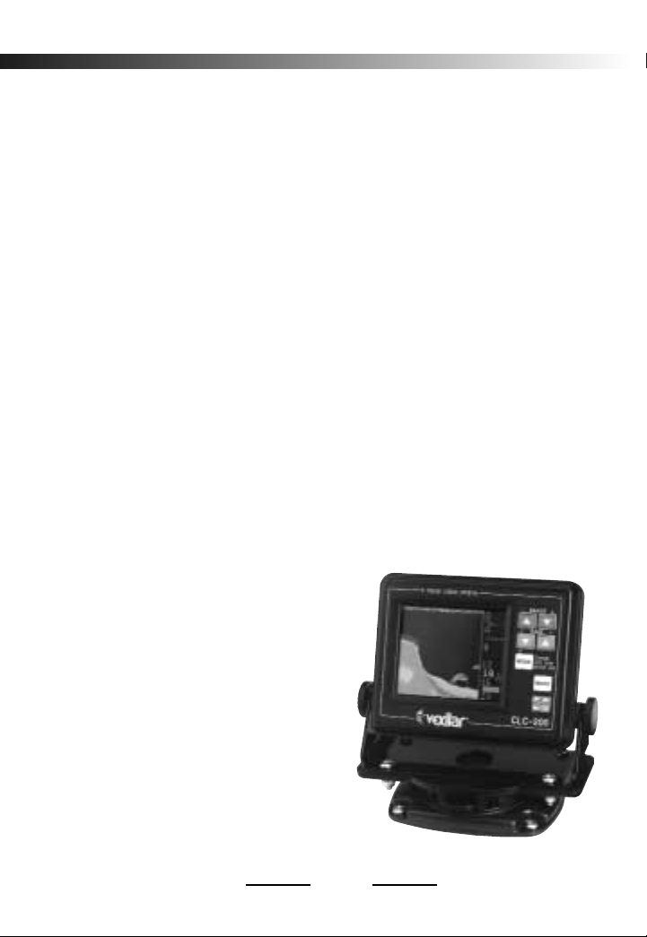
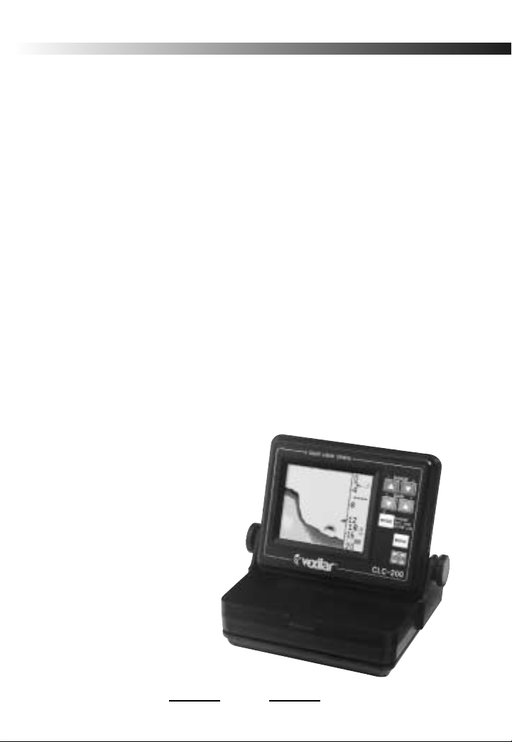
CLC-200 Gimbal version (Left)
CLC-200TM - Transom transducer
CLC-200PK - Puck style transducer
CLC-200BW Boundary Waters
portable version (Right)
Page 4
4
UNIT ASSEMBLY (Gimbal Version)
You will need to
find a place to mount
the CLC-200 that will
make it easy to view
and reach. You must
provide the unit with
power and mount the
transducer in an effective location.
MOUNTING THE UNIT
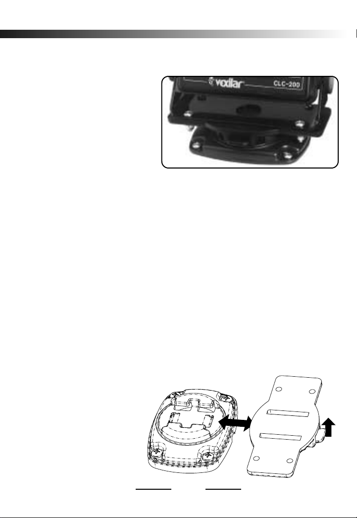
Attach the CLC-200 to the ProMount™ bracket system.
First, remove the platform by lifting the tab and pulling it
forward, as in figure 4. Use the supplied hardware with
locking washers to securely attach your unit to the removable platform section. Be sure you mount the unit to the
ProMount
™ platform so that the “lift” tab is facing forward.
You are now ready to locate the permanent base. First
look for a flat area for mounting. If you are going to drill
holes in your dash or deck to run cables, make sure you
spend a little time to place the holes in the right spot before
beginning. Allow for
plenty of movement
for your electronics
and cables. If you are
drilling a large hole
to accommodate the
cable connectors, you
may want to position
Lift
Pull
Figure 4
Page 5

5
your base directly over the hole
using the hole cover spacer
gasket. Be sure to run cables out
the back side of the spacer
gasket which has the pre-cut
groove. (See figure 5 )
Now mark the center of each
of the four holes with a fine point
marker or center punch. Pre-drill
the mounting holes using a 1/8" drill bit and use the
supplied mounting screws. DO NOT OVERTIGHTEN THE
SCREWS.
When reattaching the ProMount platform (unit attached)
to the mounted base, slide it back into position until you
hear a loud“click”. This confirms it is locked into place.
IN-DASH MOUNTING
The CLC-200 can be mounted in
the dash of your boat using the
optional In-Dash Mounting Kit (part#
IDK001). This kit will contain the
necessary hardware and instructions
to complete the installation.
CONNECTING POWER
Plug the 2 pin connector into the back of the unit. Find
the closest source of 12 volts and route the cord to it. Keep
the cord away from sharp metal edges and avoid tight
places where the cord may get crushed. Connect the white
Figure 5
CLC-200 In-Dash
Kit #IDK001
Page 6

wire to positive and the black wire to negative. If the cord
provided is not long enough, more can be added. Use 18
gauge wire minimum. Install the included 1 amp in-line
fuse, placed in the positive line, as close to the power source
as possible, to protect against shorts in the wiring.
ASSEMBLING THE TRANSOM STYLE
TRANSDUCER
Locate the transducer, and bracket hardware. This
includes;
1 - Transducer
2 - Angle Brackets
4 - Bracket Screws
2 - Bracket Plates
4 - Nuts
4 - Mounting Screws
Attach the bracket to the transducer as shown in Figure
7. The flanges of the bracket normally point outward, away
from the transducer. If mounting space is tight, you can
reverse the angle brackets and face the flanges inward.
TRANSOM TRANSDUCER INSTALLATION
When choosing an area to mount the transducer, keep
in mind that you need clear water flow across the face of
the transducer to insure a clear reading at all speeds. Try
to stay away from rivets, ribs, or strakes that would be just
in front of the transducer. They can disturb the water and
scramble the reading.
6
Page 7
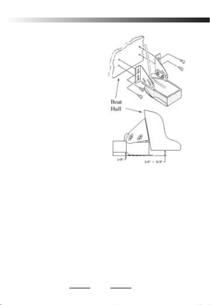
With the mounting bracket
attached to the transducer,
hold it up to the boat where
you are planning to mount it.
Mark the holes on the transom,
or mounting plate, so that
when the bottom of the
transducer is flush with the
bottom of the boat the holes are
located at the bottom of the
bracket slots. This gives you
room to "fine tune" the position
of the transducer and optimize
your reading after you've put
the boat in the water. Ideally,
the transducer should be just
under the bottom of the boat.
However, you may need to
lower it 1/2” to 5/8” to get a clear reading at top speed.
Drill out the holes and tighten the bracket to the hull
securely. Be sure to seal any holes drilled into the transom
with silicone to prevent water from leaking into the boat.
Give the transducer a slight tilt downward so that the back
is about 1/8” lower than the front. Tighten the bracket
screws and nuts securely. Run the transducer cord up to
the unit. Plug the transducer connector into the back of the
unit and screw the retaining ring down snugly.
7
Figure 7
Page 8
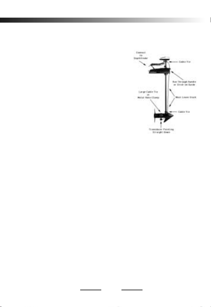
PUCK TRANSDUCER MOUNTING
To attach a Puck style transducer to a trolling
motor use the large cable tie
provided. Notice the slots in the
transducer for this purpose. Locate
the transducer on the bottom of the
lower unit (figure 8). Run the cable
up the shaft using smaller cable ties
to hold it in position. Make sure that
the motions of the trolling motor will
not damage the cable. Plug the transducer connector into the back of the
unit and screw the retaining ring down tight.
IN-HULL MOUNTING
Puck transducers can also be mounted in-hull. This
method gives high-speed reading without the worry of
having a transducer hanging on the back of the boat to get
damaged. Finding the best location for the transducer before
installation is critical. Choose a flat smooth spot near the
center of the bilge and near the back of the boat. Be sure to
make a "test run" before you permanently install the
transducer to make sure that you can get a good reading
through your hull at all speeds. When the boat is in the
water, put about a half inch of water in the bilge and hold
the transducer in the intended location. Move the it around
until you get the best reading. Mark the spot.
To install the transducer, first clean the spot of mud and
oil. Using an epoxy* or silicone glue, make a puddle, about
8
Figure 8
Page 9
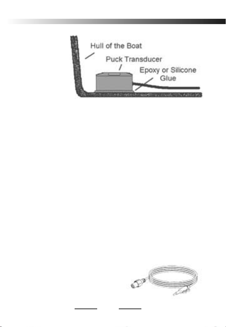
the same size as
the transducer,
on the inside of
the hull. Place
the transducer in
the glue and
press it down
firmly, gently
twisting it back and forth, making sure that there are no air
bubbles in the glue between the transducer and the hull. It
is important that you let the glue dry completely before
turning the unit on.
* If your hull is aluminum, use silicone. This material will flex with
the hull at high speeds and in rough water.
9
OPTIONAL TEMPERATURE SENSOR
To install the optional temperature sensor (part# TP0002)
use the supplied mounting screws to secure the probe to
boat transom. Alternately, you can use a plastic cable tie or
wire twist tie to secure it to existing hardware. The probe
should be in the water, but not below the hull line.
Route the cable up to the unit just as you ran the
transducer cable. Remove the plastic protective cap from
the temperature sensor jack on the back of the unit. Be sure
to keep it for future use. Plug the 8
pin connector into the CLC-200.
When you turn the unit on, the
temperature reading will appear on
the screen automatically.
TP0002
Page 10
10
UNIT ASSEMBLY (Portable Version)
Remove the gimbal knobs from the unit and then
remove the rubber washers from the knobs. Set the battery
pack down on a table top and place the unit, face down,
inside with the top of the unit opposite the battery pack
handle. Place one gimbal knob on each side of the unit.
Place the metal ends of the carry strap over each knob with
the bend pointing outward, away from the threads. Put a
flat rubber washer onto each of the threaded shafts to hold
the strap ends in place. Install the knobs into the unit,
through the battery pack. Tighten both slightly.
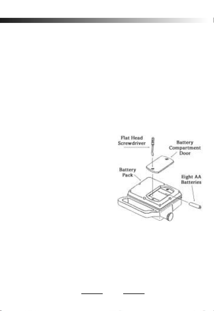
INSTALLING THE
BATTERIES
Turn the unit over to
access the battery compartment door (figure 11).
Unscrew the two retaining
screws and remove the compartment door. Install eight
AA
ALKALINE batteries (not
included) by following the
imprinted guides in the battery compartment. Replace the
compartment door and tighten the screws back into place.
Plug the power cord from the battery pack into the
CLC-200 and tighten snugly.
Note— The battery compartment is not sealed. After use in a wet
environment, remove the batteries and leave the compartment open.
This allows it to dry and minimize any corrosion that may develop.
Figure 11
Page 11

ASSEMBLING THE TRANSDUCER
Locate the transducer and bracket assembly. This
includes:
1 - Transducer
1 - Metal Bracket
1 - Suction Cup
1 - Short Panhead Screw
2 - Short Machine Screws
2 - Nuts
2 - Washers
1 - Safety rope
The suction cup installs using the single short screw.
Attach it to the hole in the flat bracket as shown in figure
12. Now locate the transducer and the remaining hardware.
Install the transducer onto the bracket as shown. Install the
two short screws through the transducer slots and into the
bracket holes. Place the washers and then the nuts onto the
screws and tighten
securely. Finally,
install the safety rope.
Tie a knot in the rope
and run it through
the upper hole in the
bracket until the knot
stops at the hole. You
will tie the other end
to the boat.
11
Figure 12
Page 12

12
TRANSDUCER MOUNTING
The suction cup bracket assembly is designed to be
mounted on the side of a canoe or kayak. However, it can
also be attached to the transom (back) of a normal fishing
boat.
Wet the suction cup and press the assembly onto the
surface of the hull in the area where you are going the attach
it. Slide the assembly up or down until the transducer is
completely in the water. You may want to bend the
bracket so that the transducer is not pointing off at an angle.
Ideally, it should point straight down when your boat is
normally loaded.
Tie the end of the safety rope to the boat. Leave as
little slack in the rope as you can. If the suction cup lets
loose, the rope can save your transducer and depth sounder
from being lost.
If you’ll be mounting to a flat
transom and you wish to get clear
readings while the boat is moving at
faster speeds, you may want to
purchase the optional Tri-Cup
bracket (part# BK0061) shown in figure 13.
IN-HULL MOUNTING
This method, gluing the transducer to the hull, gets similar results as if you were mounting the transducer externally, only there is no transducer on the outside of the boat
to get damaged by impact or tangled in weeds or fishing
line. This method works well for most types of single layer
Figure 13
Page 13

13
hull materials, including aluminum. However, the transducer is not easily removed
after installation.
Finding the best location
for the transducer before
installation is critical. Choose
a flat smooth spot near the
center of the hull and near the back of the boat. It is a good
idea to make a "test run" before you permanently install
the transducer to make sure that you can indeed get a
reading through your hull at all speeds. When the boat is
in the water, put about a half inch of water in the bottom
of the boat and hold the transducer in the intended
location. Move the transducer around until you get the best
reading. Mark the spot.
To install the transducer, first clean the spot of mud and
oil. Using an epoxy* or silicone glue, make a puddle, about
the same size as the transducer, on the inside of the hull.
Place the transducer in the glue. Press it down firmly,
gently twisting it back and forth, making sure that there
are no air bubbles in the glue between the transducer and
the hull. It is important that you let the glue dry completely
before turning the unit on.
* If your hull is aluminum, use silicone. This material will flex with
the hull at high speeds and in rough water.
Page 14

14
OPERATION
The CLC-200’s control panel contains the basic controls
you need to operate the unit. For example, Range controls
how deep the unit will read and Gain controls how much
signal will be displayed on the screen. This section describes
in detail the controls of the CLC-200.
ON/POWER/OFF
This turns the CLC-200 ON and OFF. If you choose to
modify any of the control features, your settings will be
saved in memory when the unit is turned off or disconnected from power. When you turn it on again, the unit
will operate the same way as it did when you last used it.
RANGE CONTROL
The two red buttons at the top of the control panel set
the depth range when the Auto Range Mode is off. Pressing
the (1) button changes the range to the next shallowest
range. Pressing the (2) button changes the range to the
next deeper range.
GAIN CONTROL
The two green buttons control the CLC-200’s gain level
when the Auto Gain Mode (located in the menu controls)
is set to off. Pressing the
(3) decreases the gain level
and
(4) button increases the gain level.
Page 15

MODE
During Normal Operation - The Mode button cycles
through the three different types of views; Normal, Auto
Zoom, and Bottom Lock. Zoom modes will be described
in a coming section.
While in the Menu - The Mode button is used to
toggle between menu choices. The Menu choices will be
described in the next section.
MENU
Pressing the MENU button opens the menu page.
Pressing it again will go back to the normal view. Each item
in the menu will be explained in the next section.
15
Page 16

16
MENU FUNCTIONS
Press the MENU button to enter the CLC-200’s menu
page. To select a feature item, press the (1) or the (2)
button to move the curser and highlight the desired item.
CONTRAST
Contrast controls the overall lightness or darkness of
the display. Press the (4) button or the (3) to increase
or decrease the display contrast to your preference. Contrast
adjustments should only be required after large changes in
ambient light or if you switch COLOR modes (see COLOR).
SWEEP
Sweep controls how fast the image moves across the
screen. There are 4 sweep speeds, plus STOP. The current
sweep speed is displayed as a series of red arrows on the
right side of the display. Four arrows showing indicates
the fastest sweep speed. Press the
(4) button or the
(3) to increase or decrease the sweep speed to your
preference. The sweep speed should roughly match the
speed of the boat. When in doubt, use the fastest sweep
speed setting.
AUTO_R
AUTO_R controls the CLC-200’s Automatic Range
Control feature. When set to ON, the unit will
automatically change the range to the optimal setting. To
Page 17

select whether this feature is ON or OFF, highlight the item
and press the MODE button on the control panel. In general, you will want to use the Automatic Range Control
feature. However, there may be times when you want to
lock a range setting or switch to a deeper range; for instance,
if you want to see the second echo of the bottom.
AUTO_G
AUTO_G controls the CLC-200’s Automatic Gain
Control feature. To select whether this feature is ON or OFF,
highlight the item and press the MODE button on the
control panel. When set to ON, the unit will
automatically adjust the gain level for optimal performance.
Keep the feature set to ON for normal operation. You can
set it to OFF if you want to change the gain setting to see
more or less detail.
F_ALARM
F_ALARM turns the CLC-200’s fish alarm feature on
and off. To select whether this feature is ON or OFF,
highlight the item and press the MODE button on the
control panel. When set to ON, an alarm will sound each
time the unit sees a substantial target separated from the
bottom. The fish alarm makes a series of short beeps.
17
Page 18

18
B_ALARM
B_ALARM controls the Bottom Alarm feature. To select
whether this feature is ON or OFF, highlight the item and
press the MODE button on the control panel. When this
item is ON and highlighted, you can press the
(4)
button or the
(3) to increase or decrease the minimum
depth at which the alarm will sound. The bottom alarm
makes a series of long beeps.
TEMP_ADJ
TEMP_ADJ is used to calibrate the optional
temperature sensor. Normally, this setting does not need
to be changed, but it allows for adjustment if necessary.
D_UNIT
D_UNIT is used to switch the depth unit between Feet
and Meters.
RESET
Use this feature to trouble shoot problems or to get back
to a "known state”. Highlight the RESET item and then
press the MODE button to reset all items to the initial
factory settings.
Page 19

19
USING THE ZOOM MODES
The CLC-200 offers three different types of depth views,
Standard, Auto Zoom, and Bottom Lock. Pressing the Mode
button on the front panel cycles through the different
settings.
Standard - This view is the normal depth view. It shows
the entire water column from the surface to the bottom.
This view shows the maximum amount of history, as it uses
the entire width of the graphical view screen.
Auto Zoom - This view splits the graphical screen into
two parts. The right side shows the the Standard view. the
left side shows a magnified view of the bottom of the
current depth range. This view allows for an increased
ability to see small structure and depth changes. It also
makes targets very close to the bottom much easier to see.
Bottom Lock - This mode also splits the screen into two
parts and works much the same as the Auto Zoom feature.
However, Bottom Lock identifies the bottom signal and
“locks” it into position on the zoom display. Adepth scale
appears in this mode.The bottom will always line up with
the zero mark. The numbered foot marks shown are feet,
or meters, away from the bottom. This mode can be very
useful when trying to see fish and structure near the
bottom when in heavy waves or over quick changes in
depth.
Page 20

20
UNDERSTANDING THE COLORS
The CLC-200’s color LCD display gives you much more
information that a normal single color unit. The 5 different
display colors of the CLC-200 represent five different
levels of sonar signal strength. This is very useful for
helping you determine bottom content, target size and
target position. In addition, the CLC-200 offers two
different color modes. MODE 1 shows a light background
and MODE 2 show a black background.
SIGNAL MODE 1 MODE 2
Echo 1 (Strongest) Black Red
Echo 2 Red Yellow
Echo 3 Green Green
Echo 4 Blue White
Echo 5 (Weakest) Yellow Blue
Background White Black
Page 21

21
TYPICAL INDICATIONS
If the AUTO_R AND AUTO_G modes are set to on, the
CLC-200 will find bottom and adjust the gain for the best
view automatically. This can take just a short moment or a
few minutes, depending on the depth and conditions. As
soon as the bottom begins to sweep across the screen in the
graphical view, the digital readout of the depth will appear
in the information view.
You can determine the general hardness of the bottom
by looking at the color content and width of the bottom
signal. Generally, harder bottoms will contain the stronger
echo colors and be of a fairly narrow width. Softer bottoms
will contain weaker echo colors and have a wider overall
width.
Figure 16
Surface Line
Bottom
Fish
Current
Depth
Depth Scale
Scroll Rate
Gain
Level
Battery
Power
0 - 100 %
AutoRange (on)
AutoGain
(off)
Page 22

22
SEEING FISH
Fish will appear as distinctive targets above or very
close to the bottom signal. The colors will help you
identify fish from floating debris. If the target appears large
in size and contains stronger echo colors, you can assume
it's something significant, like a fish. If the target appears
smaller or broken up and contains weaker echo colors, you
can assume it is bait fish or floating debris. However,
sometimes this can indicate a fish away from the boat, in
the outer area of the transducer cone area.
SURFACE CLUTTER
The line of information going across the top of the
display represents the surface of the water. This line can
get quite wide at times, due to surface clutter. Tiny marine
life, such as algae or plankton, can be responsible for this.
Choppy or rough waters can also be a cause as tiny air
bubbles are forced down under the surface. Surface
clutter has little effect on the performance of the unit.
HIGH SPEED OPERATION
The CLC-200 can read depths at almost any boat speed.
Due to the limited speed of the display, the displayed
bottom may be some distance behind you, depending on
how fast the boat is traveling. Once the boat starts to plane,
turbulence will develop behind the transom. If your
transducer is poorly mounted, the unit will lose the
Page 23

23
bottom at a certain boat speed. This is due to all of the air
bubbles in the turbulent water. Readjustment of the
transducer mounting should solve this problem.
SHALLOW WATER OPERATION
When the CLC-200 is in the AUTO mode, it
automatically senses the bottoms depth and tries to keep
the best view at all times. Although the display may not
show it, the CLC-200 is monitoring basic sonar signals such
as the bottoms second echo and various target's signal
strengths. This way it can maintain the optimum gain level,
automatically, for you.
In very shallow water (less than 3 feet) the unit can get
"over-welmed". In this condition the unit can show
erroneous information. The graphic display will become
overly cluttered and the digital numbers on the display can
read depths that are much deeper than reality. These depths
are actually multiple echoes of the real bottom. It is
important to use caution when navigating in shallow
waters. Use common sense. Don't rely solely on your
depth finder.
It often helps to turn off the automatic range and gain
features and manually set the range to the shallowest
setting and the gain to a low level. If the digital depth
reading doesn't seem right, it is probably a multiple of the
correct depth. Use the graphic display as a better reference.
Page 24

24
FREQUENTLY ASKED
QUESTIONS
Q - Can the CLC-200 be used for Ice Fishing?
A - Yes, but it’s performance may be very limited. LCD
depth sounders in general do not work well for ice fishing.
The type of display has significant speed and temperature
limits as opposed to flasher depth sounders which are more
popular for ice fishing.
Q - Why doesn’t the CLC-200 have a backlight for night
use?
A - This unit incorporates a reflective type of color LCD.
This technology uses ambient light to illuminate the
pixels. Backlighting will not work, front lighting is required.
The unit can be used at night, although the user must
provide adequate front lighting.
Q - Can I convert my Portable CLC to a gimbal version or
convert my gimbal version to a portable?
A - Yes, simply contact Vexilar for the conversion kit
required (see page 32).
Page 25

MAINTENANCE
Maintenance for the Boundary Waters CLC-200 is very
simple. There, simply, is not that much to maintain. Because
of this, problems can sneak up on you if you're not careful.
The unit should be removed whenever the boat is
parked to guard against theft. Don't store it in a place that
may fill with water.
Power connections need constant checking. Corrosion
can develop and cause intermittent or loss of operation.
Spray the power connector pins and battery compartment
contacts with silicone to prevent this. Remove the
batteries before you put the unit away for storage.
The transducer should be checked for scratches and
cracks which can reduce the units sensitivity. Cuts or breaks
in the cord should be repaired as soon as possible so
corrosion doesn't attack the wire. Periodically clean the face
of the transducer with a mild soap An oily film can
develop which will cause weak readings.
Clean the face of the unit with a mild soap and a clean
soft towel. Don't submerge the unit when cleaning.
25
Page 26

26
Possible Cause
TROUBLE SHOOTING
Unit is turned on, but there is no
display.
Battery voltage may be too low.
The unit will show no display if
the voltage is below 8.5 volts.
Unit will not turn on.
Check for proper battery polarity and that you have fully
charged, working batteries.
Unit runs well for a short time,
then the unit quits.
Bad battery. Check voltage indicator on display to insure you
have power remaining.
Unit runs and shows display
light, but does not read depth.
Transducer is not plugged in or
not in contact with the water.
Unit works, but needs high gain
to see bottom or targets.
Transducer is not aimed correctly or needs to be cleaned.
Unit works, but has too many
lines on the display. Can't tell
what is what.
Many air bubbles or very small
targets in the water.
Unit works well when sitting
still or at slow trolling speeds,
but loses reading when the boat
speeds up.
Improper transducer installation
or adjustment. There is a loss of
clear water flow across the face
of the transducer when the boat
reaches a certain speed.
Unit works, but shows noise
when the engine is started or the
electric trolling motor is turned
on.
Improper ground or missing
ground in electrical system.
Defective engine or trolling
motor.
Unit turns on, but the display is
very dim or does not appear.
Outside temperature is too
warm or too cool.
Symptom
Page 27

OTHER VEXILAR PRODUCTS
The Edge
The Edge, model LC-507, is the ulti-
mate LCD depth sounder. It’s unique
design incorporates two transducers
running at the same time. The split
screen view is like having two different
depth finders built into one unit.
The LPS-1 Handheld
The LPS-1 Handheld depth find-
er is perfect for finding the right spot.
Whether you’re canoeing, ice-fishing, or scuba diving. A push of the button display the depth
as an easy to read digital number for ten second before
shutting itself off. Runs on 1 9 volt battery.
The FL-18 Color Flasher
The FL-18 is the ultimate is flasher
technology. It has features such as splitscreen zoom, a low power mode for shallow water, and a super bright display.
The FL-18 Pro Pack is the unit to own for
ice fishing. It incorporates a 7.2 amp/hr
battery, easy to use charger, battery status indicator all
housed in a compact Porta-case designed to fit in the
bottom of a standard 5 gallon bucket.
27
Page 28

28
BATTERY STATUS INDICATOR
The Vexilar Battery Status Indicator
works with all 12 volt batteries and can
be permanently mounted or used as a
portable unit. It monitors your battery
constantly as it is discharging and
charging. Battery charge status is indicated with highly visible colored LED
lights.
12 VOLT SEALED LEAD ACID BATTERY
WITH CHARGER
This Vexilar Battery was designed
for sportsmen on the go, with rugged
construction and design features that
make it ideal for summer and winter
use. With a near "bulletproof"
charger, this system packs enough power to run your
equipment for hours, and for years to come.
Page 29

P-160 CARRYING CASE
The unique Vexilar Flasher Carrying
Case holds your FL-18, CLC-200, or
other manufacturer's sonar or GPS. It
has space for your transducer, a
rechargeable battery, and the Vexilar
Battery Status Indicator. The round base
is just the right size to fit down inside a
standard 5 gallon bucket.
104 DEPTHERM
The fishing odds are on your side
when you use DEPTHERM. It tells you
quickly and accurately what temperatures
are below your boat and it also tells you
the temperature at a specific depth. If your
DEPTHERM indicates that the water temp
is wrong for the species you're after, you
can quickly move.
29
Page 30

30
OPTIONAL TRANSDUCERS
HIGH SPEED TRANSDUCERS
TB0044
19 Degree Transom Mount High
Speed Transducer. Comes with the
Mounting Bracket and 25 Feet of Cable.
TB0030
9 Degree Transom Mount High Speed Transducer.
Comes with the Mounting Bracket and 25 Feet of Cable.
TB0045
Dual Beam 9/19 Degree Transom Mount High Speed
Transducer. Comes with the Mounting Bracket and 25 Feet
of Cable. Built-In Switch Box must be Mounted within 3
Feet of the Depth Finder.
TB0084
12 Degree Transom Mount High Speed Transducer.
Comes with the Mounting Bracket and 25 Feet of Cable.
BK0044
Optional Suction Cup Mount for all of the above High
Speed Transducers. Dual suction cups for extra holding
power.
Page 31

PUCK STYLE TRANSDUCERS
TB0023
1” 19 Degree Puck Transducer. For
Mounting on a Electric Trolling Motor,
In-Hull Mounting, Portable Use, or Ice
Fishing. Comes with 25 Feet of Cable.
BK0023
Optional Suction Cup Mount for TB0023.
TB0027
2” 9 Degree Puck Transducer. For Mounting on a Electric
Trolling Motor, In-Hull Mounting, Portable Use, or Ice
Fishing. Comes with 25 Feet of Cable.
TB0032
2”Dual Beam 9/19 Degree Puck Transducer. For
Mounting on a Electric Trolling Motor, In-Hull Mounting,
Portable Use, or Ice Fishing. Comes with 25 Feet of Cable.
Built-In Switch Box must be Mounted within 3 Feet of the
Depth Finder.
TB0087
2” 12 Degree Puck Transducer. For Mounting on a
Electric Trolling Motor, In-Hull Mounting, Portable Use, or
Ice Fishing. Comes with 25 Feet of Cable.
31
Page 32

32
SERVICE AND SUPPORT
If you find that you need help or want to order
accessories, feel free to contact us. Please have ready the
model number and, if possible, the serial number of your
product. If you’re having problems, be sure to read the
Trouble Shooting sections first.
Address
Vexilar, Inc.
200 W. 88th St.
Minneapolis, MN, 55420-2752
Telephone
(952) 884-5291 (8 am to 5 pm M-F Central Time)
Fax
(952) 884-5292
Web Site
www.vexilar.com
Email
service@vexilar.com
 Loading...