

Page 1

CONTENTS
General Description 2
Specifications 4
Unit Installation 5
Mounting the Sensor Box 6
Assembling the Transducer 6
Attaching the Sensor 7
Mounting the Transducer 8
Operation 12
Menu Functions 15
Typical Indications 22
Maintenance 26
Trouble Shooting 27
Other Products 28
Service and Support 31
Founded in 1965, Vexilar, Inc.
has a long history of bringing revolutionary technology to
the sport fishing industry. Just some of the Vexilar firsts
include: the first liquid crystal display, the first fish alarm,
the first three color display, and the first CRT and straight
line paper graphs, for the sport fisherman.
1
107 Pro Operation Manual
Page 2

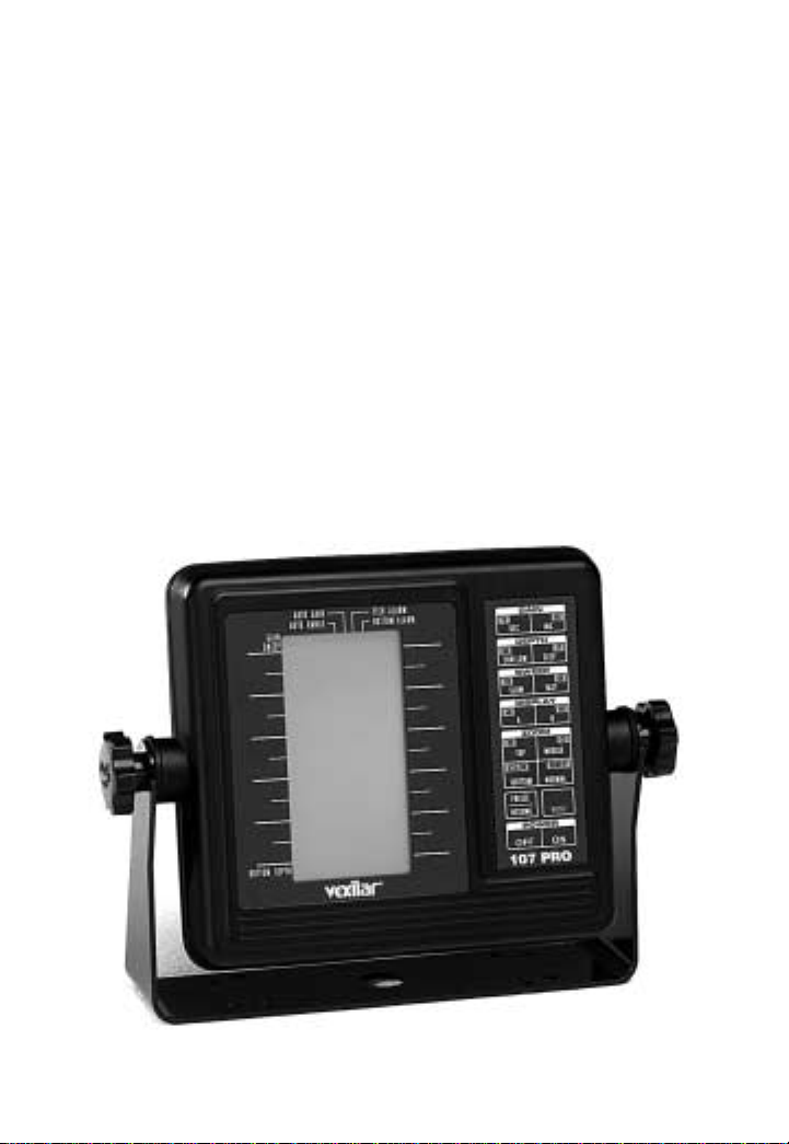
GENERAL DESCRIPTION
The 107 Pro incorporates an extremely high quality
sonar circuit with an easy to understand interface. The unit
is designed to be effective and easy to use. All the main
functions are only one button away. Range and Gain controls are selectable as fully automatic or easily controlled
manual modes independent of each other . Internal battery
backup saves all selections upon power off.
The output frequency of 107 KHz is much lower than
most depthfinders of today. This is designed to give more
output power and a greater area of coverage. The 107 Pro
can truly "arc" fish and does not need to use artificial fish
symbols.
The 107 Pro incorporates Clean Line circuitry that can
"clean out" the harder targets. The bottom, rocks, and dense
weeds are made transparent so fish are more visible near
them. On a hard rock or gravel bottom, fish on the edge of
the cone angle can actually be seen within the bottom signal. And with a 38˚ cone angle, you can cover allot of area.
There are three Zoom Zones which let you hone in on
the area you want to see best. You can zoom just the top
half, middle, or bottom half of the display. These features
are easily activated by a single press of a button. Switching
back and fourth is quick and easy.
Speed and Temperature sensors are included. Two dis-
2
Page 3
play modes provide a standard graphic view mode or a
digital mode which includes a temperature graph. There
is also a trip log feature to help keep track of the distance
you have traveled.
There are more featur es, including pr ogrammable bot-
tom alarm, fish alarm, a high speed vertical mode, and a
Clean Echo feature to eliminate interference
All told, the 107 Pro is a powerful tool for visualizing
structure and fish, in almost all situations. Quality construction and superior product support. Long Vexilar traditions that go with this unit, and everything else we produce.
3
Page 4
4
• Operating Voltage:
• Current Draw:
• Power Output:
• Frequency:
• Resolution:
• Sounding Rate:
• Display Size:
• Dimensions:
• Weight:
8.5 - 16 Volts (12 Volts Nominal)
200mA (400 mA w/Backlight On)
1200 Watts (Peak to Peak)
107 Khz
64 x 128 Pixels
700/Min.
2" x 4 3/4"
7.1"H x 9.5"W x 1.9"D
1.1 Lbs. (Unit Only)
SPECIFICATIONS
• Depth Ranges:
0-5', 0-10', 0-15', 0-20', 0-30', 0-40', 0-60', 0-80', 0-120',
0-160', 0-240', 0-320', and 0-480'.
Figure 3
Page 5

INSTALLATION
You will need to find a place to mount the 107 Pro that
will make it easy to view and reach. You must provide the
unit with power and mount the transducer and sensor
assembly in an effective location.
MOUNTING THE UNIT
Find a convenient place to mount the unit. This may
include a boat seat, deck, dash, or a portable case. Make
sure that there is plenty of room for the unit to tilt freely
without the cables binding or stretching behind the unit.
Once you have found the spot, remove the unit from the
gimbal bracket. Securely attach the bracket to the mounting surface. The screws provided are 5/8" long and ar e for
wood/carpet or dash mounting applications. An optional
removable swivel bracket is available.
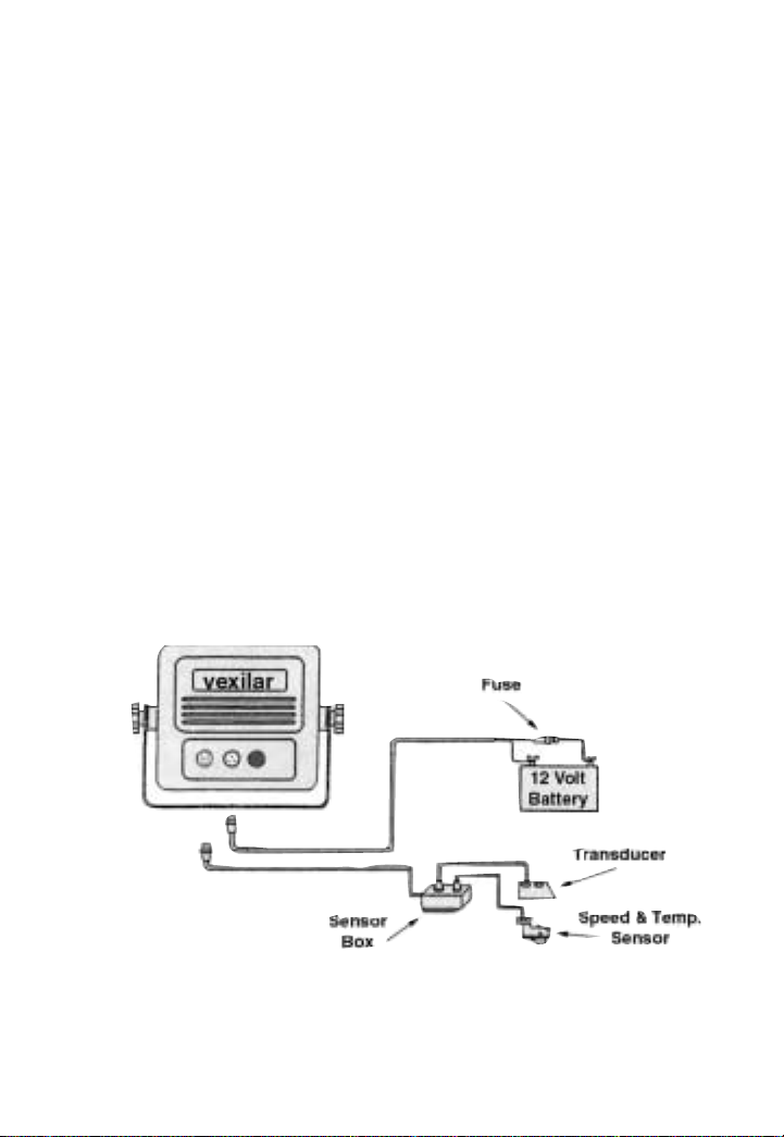
CONNECTING POWER
Plug the 3 pin connector into the back of the unit. Find
the closest source of 12 volts and route the cord to it. Keep
the cord away from sharp metal edges and avoid tight
places where the cord may get crushed. Connect the white
wire to positive and the black wire to negative. If the cord
provided is not long enough, more can be added. Use 18
gauge wire minimum. Install the included 1 amp in-line
fuse, placed in the positive line, as close to the power source
as possible, to protect against shorts in the wiring.
5
Page 6
MOUNTING THE SENSOR BOX
The sensor box needs to be located within three feet of
the main unit. It is recommended that it be fastened to a
sturdy surface. You can mount it, using the screws provided, to a flat surface or you can simply tie it to a frame
or wire harness, using cable ties which are not provided.
The sensor box is weather proof, but be sure to keep it out
of an area that may fill with water.
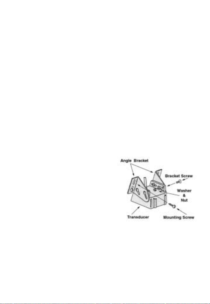
ASSEMBLING THE TRANSDUCER
Locate the transducer, and bracket hardware. This
includes;
1 Transducer
2 Angle Brackets
4 Bracket Screws
4 Washers
4 Nuts
4 Mounting Screws
Attach the bracket to the
transducer as shown in Figure 4. The flanges of the bracket normally point outward, away from the transducer. If
mounting space is tight, you can reverse the angle brackets and face the flanges inward.
6
Figure 4
Page 7
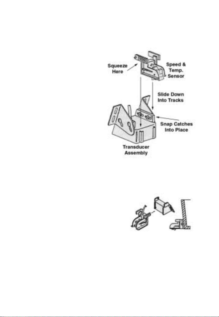
ATTACHING THE SENSOR ASSEMBLY
The speed and tempera-
ture sensor assembly attaches to the transducer as
shown. Pinch, or squeeze,
together the tabs at the top
of the sensor and slide the
assembly down into the
tracks on the back of the
transducer. Push it down
until it stops, and then, push
the tabs back outward until
the catches snap into the
holes on the transducer.
ALTERNATE SENSOR MOUNTING
If you plan on mounting the transducer inside the hull
of the boat or on an electric trolling
motor (described on page 11) you
will need to use the provided sensor mounting bracket, instead of the
transducer to mount the sensor.
CAUTION - It is a good idea to restrain the speed wheel
from spinning freely while trailering the boat. Damage may
result because there is no water to lubricate the wheel bearings. Arubber band works good for this.
7
Figure 5
Figure 6
Page 8
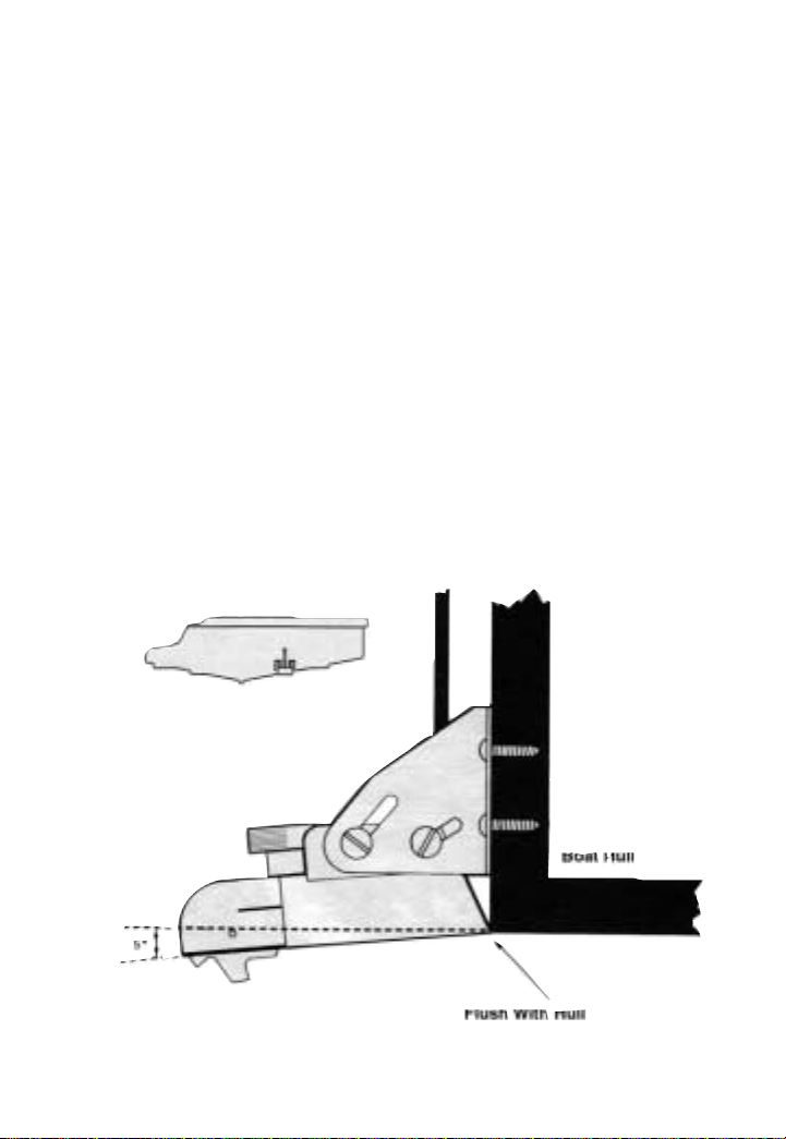
MOUNTING THE TRANSDUCER
The 107 Pro transducer is designed to be mounted on
the transom of the boat. The shape will allow a clear depth
reading at any boat speed, if properly installed.
Locate a spot similar to the one in figure 7. Keep in mind
that you need clear water flow across the face of the transducer to insure a clear reading at all speeds. Stay away from
rivets, ribs, or strakes that would be just in front of the transducer. They will disturb the water and scramble the reading. Attach the mounting bracket to the transducer and
hold it up to the boat where you are planning to mount it
(see figure 7).
Mark the four holes on the transom, or mounting plate,
8
Figure 7
Page 9

so that when the bottom of the transducer is flush with the
bottom of the boat the holes are located at the bottom of
the bracket slots. This gives you room to "fine tune" the
position of the transducer and optimize your reading after
you've put the boat back in the water. Drill out the holes
and install the transducer bracket assembly. Tighten the
screws down securely. Be sure to seal any holes drilled into
the transom with silicone to prevent water from leaking
into the boat.
Route the transducer cord up to the unit taking the
same. care as you did when you routed the power cord.
Make sure that the cord is restrained and not allowed to
flop around in the wind. This can cause stress on the wire
inside the cable, and possible breakage. Plug the transducer
connector into the back of the unit and screw the retaining
ring down tight.
After you have put the boat back in the water confirm
that you can maintain a bottom reading at all boat speeds.
If not, loosen the bracket screws and tilt the transducer
some more. Keep the front edge flush with the boat, but
drop the back edge down a little more. If changing this
angle several times does not clear up the reading, loosen
the mounting screws and slide the transducer down, slightly. Repeat these adjustments until you get a clear reading.
Finally, make sure that all mounting screws are tight.
Fill any gap between the transducer and the hull with
silicone to prevent a rooster tail from shooting up behind
the boat.
9
Page 10

PORTABLE MOUNTING
An optional suction cup bracket can be
used to temporarily attach a transducer to the
transom or side of the boat. The cups should
be placed in a location where they will not be
torn off when the boat goes high speed, but
still just low enough to maintain the high speed reading.
The optional BK0044 suction cup mounting plate works
well for this application.
An arm assembly that clamps to the transom or side of
the boat can also be used to hold the transducer. Simply
attach the transducer to the end of the arm using cable ties
or tape. If the arm is constructed of metal tubing insulate
the transducer from the arm by wrapping electrical tape
around the arm. This prevents "ringing" which can be displayed as noise near the surface.
IN-HULL MOUNTING
Finding the best location for the transducer before
mounting is critical. Choose a flat smooth spot near the
center of the bilge and near the back of the boat. It is a good
idea to make a "test run" before you permanently install
the transducer. This makes sure that you can, indeed, get
a reading through your hull, and when the boat is on plane.
Put about a half inch of water in the bilge and hold the
transducer in the intended location. Move the transducer
around until you get the best reading. Mark the spot.
To install the transducer , clean the spot of mud and oil.
10
Page 11

Using an epoxy or silicone
glue, make a puddle about
the same diameter as the
transducer on the hull. Place
the transducer in the glue.
Press it down firmly, gently
twisting it back and forth,
making sure that there are no
air bubbles in the glue
between the transducer and
the hull. Let the glue dry completely before turning the unit
on.
TROLLING MOTOR MOUNTING
Use two hose clamps or large cable ties (not included)
to attach the transducer to an electric trolling motor. Using
the slots in the transducer, run the ties through them and
around the motors lower unit. Locate the transducer on the
bottom of the lower unit as in figure 10. Run the cable up
the shaft using smaller cable ties to hold it in position. Make
sure that the cable will not be
damaged by the movement of
the trolling motor. Plug the transducer connector into the back of
the unit and screw the retaining
ring down tight.
11
Figure 10
Page 12

OPERATION
Figure 1 1 shows the main contr ols of the
107 Pro.
POWER - OFF / ON
Turns the 107 Pro OFF and ON. Press the
ON button to turn the unit on. You will hear
a short beep when the unit powers on. Press
the OFF button to turn the unit off. All feature settings will be stored in memory so that
when you turn the unit on again, it will operate the same way as it did when you last
used it.
MENU
Pressing the menu button enters the first menu page.
Pressing this button while in a menu page moves you to
the next menu page. Menu items will be explained in the
next section.
FREEZE / RESUME
During normal operation, press the FREEZE / RESUME
button to stop the movement of the display. Press the button again to resume back to normal operation.
While in any menu page, press the FREEZE / RESUME
button to return to normal operation.
12
Figure 11
Page 13

GAIN CONTROL
The 107 Pro comes selected from the factory to run in
automatic gain mode. The unit will monitor the conditions
and adjust the gain, or sensitivity, to an optimum level. If
you wish, you can over ride this feature in the MENU settings and adjust the gain manually. Then, you will press
the DEC button to decrease the gain level. Press the INC
button to increase the gain level.
RANGE CONTROL
The 107 Pro comes selected from the factory to run in
automatic range mode. The unit will monitor the depth
and change the range for you when the depth changes. You
can override this feature in the MENU setting and change
the range manually. Press the SHALLOW button to change
the range to the next shallower range. Press the DEEP button to change the range to the next deeper range.
SWEEP
SWEEP controls how fast the display moves across the
screen. This speed should, roughly, match the speed of the
boat. Press the SLOW button to slow down the display one
step. Press the FAST button to speed up the display one
step.
13
Page 14

DISPLAY
Selects between two different display modes. Press the
A button to view the standard graphical view. Press the B
button to view the "windowed" view. This view provides
depth, temperature, speed, and log information in large,
easy to read, numbers. It also displays a temperature graph
and an A-Mode depth display. A-mode is an instantanious
vertical depth display, described in the next section.
ZOOM
The 107 Pro has three different Zoom Zones. You can
select to view only the top half, middle half, or bottom half
of the depth. Using a Zoom Zone, effectively, doubles the
display resolution, making things appear twice as large.
The Zoom Zone feature works in both standard and AMode views.
Press the TOP button to view only the top half of the
depth. Press the MIDDLE button to view only the middle
half of the depth. Press the BOTTOM button to view only
the bottom half of the depth. Press the NORMAL button
return to the standard display mode.
14
Page 15

MENU FUNCTIONS
Press the MENU button to enter the first menu page.
Press the MENU button again to enter the second menu
page.
AUTO GAIN
Press MENU, then, the 1, or DEC, button to enter the
AUTO GAIN submenu. This feature has three available
settings.
Press the 1 button to turn off the automatic gain feature.
You now must change the gain level manually using the
GAIN buttons on the front of the unit. Press the 2, or SHALLOW button to turn the automatic gain control on to the
High setting. Press the 3, or SLOW, button to select the Low
automatic gain setting. Press the FREEZE / RESUME button to return to the normal view.
The High setting will keep the gain level higher than
the Low setting. The default setting is High, but better
results in shallow or weedy waters may be possible with
the Low setting.
AUTO RANGE
Press MENU, then the 2, or SHALLOW, button to enter
the Auto Range submenu. Press the 1 button to turn the
auto range feature off. Press the 2 button to turn the feature on.
15
Page 16

BOTTOM ALARM
Press MENU, then the 3, or SLOW, button to enter the
Bottom Alarm submenu. Press the 1 button turn this feature off, the default. Press the 2 button to turn this feature
on.
There are two values to be entered in the alarm settings.
There are also several different ways in which the alarm
works, depending on the depth values you enter . The best
way to describe this feature is by example.
Example 1 - To set the alarm to sound whenever the
depth gets less than three feet, press the 4 button to enter
the upper alarm limit. Press the 0 button to enter the value
of zero. Press the SET button to enter this value. If you make
a mistake entering the value, press the CLR button and
then retry. Now, press the 5 button to set the lower alarm
limit. Press the 3 button, and then, the SET button to enter
the value of three. Finally, press FREEZE/RESUME
Example 2 - To set the alarm to sound whenever the
depth is between five and fifteen feet, press the 4 button to
enter the upper alarm limit. Press the 5 button to enter the
value of five. Press the SET button to enter this value. If
you make a mistake entering the value, press the CLR button and then retry. Now, press the 5 button to set the lower
alarm limit. Press the 1 button, and then, the 5 button.
Finally, press the SET button to enter the value of fifteen.
Then, press FREEZE/RESUME
16
Page 17

Example 3 - To set the alarm to sound whenever the
depth gets less than five feet or more than fifteen feet, press
the 4 button to enter the upper alarm limit. Press the 1 button and then the 5 button to enter the value of fifteen. Press
the SET button to enter this value. If you make a mistake
entering the value, press the CLR button and then retry.
Now, press the 5 button to set the lower alarm limit. Press
the 5 button, and then, the SET button to enter the value of
five. Then, press FREEZE/RESUME.
Example 4 - To set the alarm to sound whenever the
depth gets more than fifteen feet, press the 4 button to enter
the upper alarm limit. Press the 1 button, and then, the 5
button to enter the value of fifteen. Press the SET button to
enter this value. If you make a mistake entering the value,
press the CLR button and then retry. Now, pr ess the 5 button to set the lower alarm limit. Press the 0 button, and
then, the SET button to enter the value of zero. Then, press
FREEZE/RESUME.
FISH ALARM
Press MENU, then, the 4 button, to enter the Fish Alarm
submenu. There are two sensitivity settings for the Fish
Alarm. Press 2 to activate the alarm and set the sensitivity
to High or 3 to set it to Low sensitivity. When set to High,
the alarm will sound on all fish targets. When set to Low,
it will only sound on larger fish targets. Set the Upper and
Lower limits the same way as described in the Bottom
Alarm section.
17
Page 18

LIGHT
To turn on the backlight, for night use, press the MENU
button, then, the 5 button to enter the Light submenu. Press
the 2 button to turn it on and the 1 button to turn it off.
CONTRAST
To adjust the liquid crystals display contrast, press
MENU, then, the 6 button to enter the Contrast adjustment
submenu. Press any numbered button between 1 and 8 to
adjust the Contrast. 1 will give the lightest setting and 8
will give the darkest setting.
TEMP
To turn the Temperature sensor on, press MENU, then,
the 7 button to enter the Temp submenu. Press the 2 button to turn it on and the 1 button to turn it off.
SPEED
To turn the Speed sensor on, press MENU, then, the 8
button to enter the Speed submenu. Press the 2 button to
turn it on and the 1 button to turn it off. If you find that
your reading is not correct you can correct it in this submenu. Press the 3 through 9 buttons to correct the r eading
as needed.
18
Page 19

LOG
The Log is a feature that works with the Speed sensor
to keep track of total distance traveled. Press MENU, then,
the 9 button to enter the Log submenu. Press the 2 button
to turn it on and the 1 button to turn it off. The Log will
keep accumulating your distance traveled until you turn
it off. You can turn the Log back on to add more distance
or press the 3 button to clear the Log and start a new reading.
SIMULATION
The 107 Pro has a built-in Simulator to help you learn
or demonstrate the functions of the unit. The Simulator is
a short program which simulates a real world situation. All
of the front panel controls and menu functions can be used
with the simulator.
Press the MENU button twice, then, the 1 button to enter
the Simulator submenu. To turn the simulator on, press the
2 button. To turn it off, press the 1 button.
SYSTEM RESET
Press the MENU button twice, then, the 2 button to enter
the system reset submenu. RESET returns all settings back
to the factory original settings. Press the 2 button to reset
the system. Use this feature to trouble shoot problems or
to get back to a "known" state . Caution - All settings,
including the Log value, will be erased.
19
Page 20

CLEAN LINE
Clean Line is a feature which can help determine the
hardness of the bottom. Clean Line "cleans out" the target
signal on harder objects. Ahard bottom will appear cleaned
out in the center. Asoft bottom will be all black.
Press the MENU button twice, then, the 3 button to enter
the Clean Line submenu. There are two levels, High and
Low. Use High over softer bottom and Low over harder
bottom. Press the 2 button to activate the Clean Line feature on High. Press the 3 button for Low.
CLEAN ECHO
Clean Echo reduces interference from other depthfinders running on the same frequency. Press the MENU button twice, then, the 4 button to enter the Clean Echo submenu. To turn it on press the 2 button. To turn it off press
the 1 button.
A-MODE
A-Mode gives an instantaneous, vertical, representation of the depth below. It gives you the ability to recognize bottom changes and targets before they scroll onto the
normal display.
To enter the A-Mode submenu, press the MENU button twice, then, the 5 button. To activate the feature press
the 2 button. To turn it off press the 1 button.
20
Page 21

UNIT
You can select the unit of measurement for depth, tem-
perature, and speed. Press MENU twice, then, the 6 button to enter the Unit submenu.
For Depth, you can select Feet, Fathoms, or Meters. Press
the 1 button for Feet, the 2 button for Fathoms, or 3 for
Meters.
For Temperature you can select from degrees Fahr enheit,
the 4 button, or Centigrade, the 5 button.
For Speed you can select from miles per hour (MPH),
knots, or kilometers per hour (KPH). Press the 6 button for
MPH, the 7 button for knots, or 8 for KPH.
LOG COUNT
Log Count keeps track of your distance traveled, even
when the Log feature is turned off. You can turn the Log
display on or off, and the Log will continue counting at all
times. To start a new Log Count you will need to Clear the
old count in the Log submenu.
Press the Menu button twice, then, the 7 button to enter
the Log Count submenu. To activate the feature, press the
2 button. To turn it off, press the 1 button. The default is
off.
21
Page 22

22
TYPICAL INDICATIONS
Once the boat is in the water and you have turned on
the 107 Pro, in automatic range mode, you must allow it
time to find the bottom. This can take just a short moment
or several minutes, depending on the depth and conditions.
If you are operating in manual range mode, you will need
to adjust the range. As soon as the digital depth appears,
the graphical representation of the bottom will start to move
across the screen. The appearance of the bottom signal can
give you information as to what type of bottom you are
over.
Using the 107 Pro's Clean Line feature, you can help
determine the hardness of the bottom. Clean Line "cleans
out" the target signal on harder objects. Ahard bottom will
appear cleaned out in the center. A soft bottom will be all
black.
SEEING FISH
Fish passing through the cone will appear as an arc, or
partial arc. Here is how it works. The 107 Pro has allot of
power and a very wide cone angle. When the fish appears
at the edge of the cone it is far away from the transducer.
The display begins to draw the target on the screen. As the
fish gets closer to the center of the cone the target appears
to get shallower and the unit draws the target line getting
shallower . When the fish passes to the other side of the cone
it appears to get deeper . The unit now draws the line going
Page 23

deeper, until it is no longer visible. The result is an arc
drawn on the display. If the fish passes on the edge of the
cone you will only see a partial arc. This arc affect will be
more evident the deeper the fish target is. Also, the ar c will
be sharper as the boat speed increases.
The Clean Line feature can also help you identify fish
from floating debris. If the target appears cleaned out, you
can assume it's something significant, like a fish. In heavy
weeds this can be difficult to see.
SURFACE CLUTTER
The line of information going across the top of the dis-
play represents the surface of the water. This line can get
quit wide, at times, due to surface clutter . Tiny marine life,
such as algae or plankton, can be responsible for this.
Choppy or rough waters can also be a cause as tiny air bubbles are forced down under the surface.
Surface clutter has little effect on the performance of
the unit. It can, however, make things difficult to see in
shallow water.
HIGH SPEED OPERATION
The 107 Pro can read depths at almost any boat speed.
Due to the limited speed of the display, the displayed bottom may be some distance behind you, depending on how
fast the boat is traveling. Use the A-Mode feature to help
you with high speed readings. Here, high speed is defined
as any speed at or above the speed at which the boat planes
out.
23
Page 24

24
Once the boat starts to plane, turbulence will develop
behind the transom. If your transducer is poorly mounted,
the unit will lose the bottom at a certain boat speed. This
is due to all of the air bubbles in the turbulent water.
Readjustment of the transducer mounting should solve this
problem.
SHALLOW WATER OPERATION
When the 107 Pro is in the automatic range and gain
modes, it automatically senses the bottom depth and tries
to keep the best view at all times. Although the display may
not show it, the 107 Pro is monitoring basic sonar signals,
such as the bottoms second echo and various target's signal strengths. This way it can maintain the optimum gain
level, automatically, for you.
In very shallow water (less than 3 feet) the unit can get
"over-welmed". In this condition the unit will show erroneous information. The graphic display will become mostly black and the digital numbers on the display will read
depths that are much deeper than reality. These depths are
actually multiple echoes of the real bottom. It is important
to use caution when navigating in shallow waters. Use
common sense. Don't rely solely on your depthfinder.
It often helps to turn off the automatic features and manually change the range to the 5 or 10 foot range. Also, turn
the gain level down to the minimum. If the digital depth
reading doesn't seem right, it is probably a multiple of the
correct depth. Use the graphic display as a better reference.
Page 25

25
ICE FISHING
The stable platform of ice lets you concentrate on your
bait and the fish around it. The bottom becomes less important because it never changes. The only movement on the
display is of your bait and fish.
Unlike open water use, the direction in which the trans-
ducer is pointed is very critical. You want your bait to be
located in the dead center of the cone sound, directly under
the transducer. This way you can see very small baits at
low gain settings and also see fish come in from all sides.
The transducer must be attached to an adjustable arm so
that it can be manually pointed directly at the bait.
Sometimes it helps to attach a bubble level to the transducer so that you know when it's straight.
After your system is properly set up, adjust the gain
until you see your bait. You may need to readjust the gain
control to keep the bait in view. This is due to the changing condition and position of your bait. If you are using a
swimming bait or a lure that darts to the side as it's jigged,
you will see the signal change as the bait moves. Sometimes
it may even disappear if the bait goes out of the cone of
sound.
Page 26

MAINTENANCE
Maintenance for the 107 Pro is very simple. There, simply, is not that much to maintain. Because of this, problems
can sneak up on you if you're not careful.
The unit should be removed whenever the boat is
parked to guard against theft. Don't store it in a place that
may fill with water.
Power connections need constant checking. Corrosion
can develop and cause intermittent or loss of operation.
Spray the power connector and battery terminals with silicone to prevent this. Remove the connections before you
put the boat away for storage.
The transducer should be checked for scratches and
cracks which can reduce the units sensitivity. Cuts or breaks
in the cord should be repaired as soon as possible, so corrosion doesn't attack the wire. Periodically clean the face
of the transducer with a mild detergent. An oily film can
develop which will cause weak readings.
Clean the face of the unit with a mild soap. Don't submerge the unit when cleaning.
26
Page 27

Possible Cause
TROUBLE SHOOTING
Unit is turned on, but there is no
display.
Battery voltage may be too low .
The unit will show no display if
the voltage is below 8.5 volts.
Unit will not turn on.
Check for proper battery polarity and that you have fully
charged, working batteries.
Unit runs well for a short time,
then the unit quits.
Bad battery. Voltage may be
good when checked, but may
fall as it is loaded.
Unit runs and shows display
light, but does not read depth.
T ransducer is not plugged in or
not in contact with the water.
Unit works, but needs high gain
to see bottom or targets.
Transducer is not aimed correctly or needs to be cleaned.
Unit works, but has too many
lines on the display. Can't tell
what is what.
Many air bubbles or very small
targets in the water.
Unit works well when sitting
still or at slow trolling speeds,
but loses reading when the boat
speeds up.
Improper transducer installation
or adjustment. There is a loss of
clear water flow across the face
of the transducer when the boat
reaches a certain speed.
Unit works, but shows noise
when the engine is started or the
electric trolling motor is turned
on.
Improper ground or missing
ground in electrical system.
Defective engine or trolling
motor.
Unit does not save settings in
memory. Does not sound normal
beeps when turned on.
Internal lithium battery is dead.
Replace with new. Common
number is CR2032.
Symptom
27
Page 28

OTHER VEXILAR PRODUCTS
The Boundary Waters LC-10
Powered by eight AAbatteries, the
compact, ultra lightweight Boundary
Waters LC-10 is perfect for canoes,
portages, or fly-ins. It has great performance and plenty of friendly features.
The FL-8SLT Color Flasher
The FL-8SLT is a compact and lightweight flasher designed for serious
anglers. Besides indicating depth, the unit
also shows changes in bottom content
and conditions. It has three display colors. Red indicates a strong signal and
green indicates a weak signal. Orange is a medium signal.
The FL-8ID In-Dash Flasher
Enjoy the same sensitivity, accuracy,
and reliability of the FL-8SLT in the FL8ID. Mount it in your dash, bow, or transom control panel. The FL-8ID has most
of the performance features of the FL-8SLT.
28
Page 29

29
PORTA CASE
The unique Vexilar Flasher Porta Case
holds your FL-8SL T, 107 Pro, or other manufacturer's sonar or GPS. It has space for
your transducer, a rechargeable battery,
and the Vexilar Battery Status Indicator.
Just set it down on the ice or boat seat, position the transducer and turn on your unit. The round base
is just the right size to fit down inside a standard 5 gallon
bucket.
104 DEPTHERM
The fishing odds are on your side when you use
Deptherm. It tells you quickly and accurately what
temperatures are below your boat and it also tells
you the temperature at a specific depth. If your
Deptherm indicates that the water temp is wrong
for the species you're after, you can quickly move.
12 VOLT SEALED LEAD ACID BATTERY
WITH BATTERY CHARGER
This battery was designed for sports-
men on the go, with rugged construction
and design features that make it ideal for
summer and winter use. With a near "bulletproof" charger, this system packs enough power to run
your equipment for hours, and for years to come.
Page 30

CHARGE GUARD
The Charge Guard is a foolproof way
to get the right charge into your deep
cycle and cranking batteries. Just connect
the Charge Guard to your battery, hook
up your battery charger, and walk away.
It works with most battery chargers and
gives your battery the correct charge
every time. The Charge Guard monitors
the charge going into your battery. It automatically stops
accepting charge when the battery is full, and restarts charging when the battery loses charge.
BATTERY STATUS INDICATOR
The Vexilar Battery Status Indicator
works with all 12 volt batteries and can be
permanently mounted or used as a
portable unit. It monitors your battery
constantly as it is discharging and charging. Battery charge status is indicated with
a highly visible red LED light
30
Page 31

SERVICE AND SUPPORT
If you find that you need help, feel free to contact us.
Please have ready the model number and, if possible, the
serial number of your product. Be sure to read the Trouble
Shooting sections first.
Address
Vexilar, Inc.
200 W. 88th St.
Minneapolis, MN, 55420-2752
Telephone
(952) 884-5291 (8 am to 5 pm M-F Central Time)
Fax
(952) 884-5292
Web Site
www.vexilar.com
Email
service@vexilar.com
31
Page 32

32
NOTES
 Loading...