

Vexar DVF32TMHPN-A, DVF32TMHST-A, DVF32TMHST-A1, DVF32TMHST-A2 Owner's Operation And Installation Manual
For more information, visit www.fmiproducts.com
WARNING: If the information in this manual is not
followed exactly, a re or explosion may result causing
property damage, personal injury or loss of life.
— Do not store or use gasoline or other ammable
vapors and liquids in the vicinity of this or any other
appliance.
— WHAT TO DO IF YOU SMELL GAS
• Do not try to light any appliance.
• Do not touch any electrical switch; do not use any
phone in your building.
• Immediately call your gas supplier from a neighbor’s
phone. Follow the gas supplier’s instructions.
• If you cannot reach your gas supplier, call the re
department.
— Installation and service must be performed by a quali-
ed installer, service agency or the gas supplier.
INSTALLER: Leave this manual with the appliance
CONSUMER: Retain this manual for future reference.
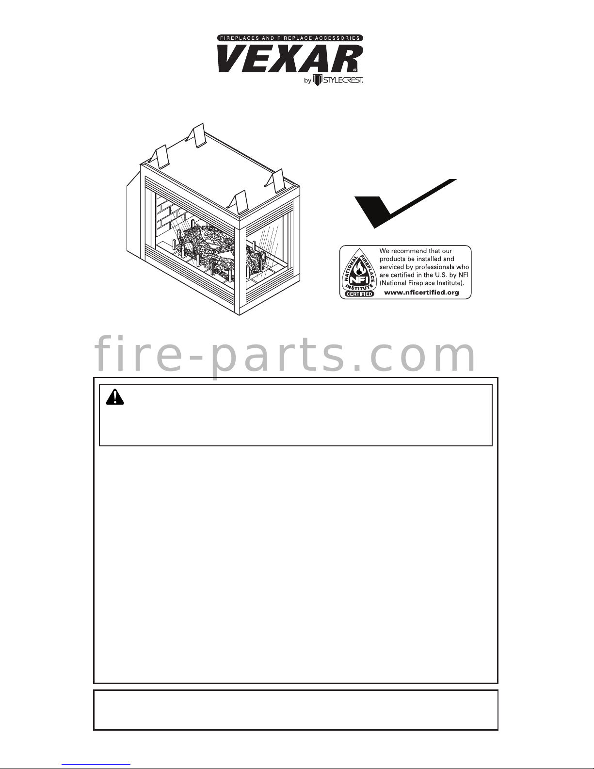
DIRECT-VENT FIREPLACE
OWNER’S OPERATION AND INSTALLATION MANUAL
PENINSULA MODELS DVF32TMHPN-A
SEE-THRU MODELS
DVF32TMHST-A, DVF32TMHST-A1 AND DVF32TMHST-A2
Peninsula Model
Shown
PFS
®
US
f i r e - p a r t s . c o m
www.fmiproducts.com
123095-01C2
WARNING: Improper installation, adjustment, al-
teration, service or maintenance can cause injury or
property damage. Refer to this manual for correct installation and operational procedures. For assistance
or additional information consult a qualied installer,
service agency or the gas supplier.
WARNING: This direct vent gas replace is intended
for use with natural or propane/LP gas only. Do not attempt to burn any solid fuels in this appliance.
This replace is manufactured for Stylecrest Inc. under
the Vexar brand name by FMI PRODUCTS, LLC.
This replace may be installed as an OEM installation
in a manufactured (mobile) home and must be installed
in accordance with the manufacturers instructions and
the Manufactured Home Construction and Safety Stan-
dard, Title 24 CFR, Part 3280 in the United States. This
replace is only for use with the type(s) of gas indicated
on the rating plate. A conversion kit is supplied with the
replace.
State of Massachusetts: The installation must be made
by a licensed plumber or gas tter in the Commonwealth
of Massachusetts.
SAVE THIS BOOK
This book is valuable. In addition to instructing you on how to install and
maintain your appliance, it also contains information that will enable you to
obtain replacement parts or optional accessory items when needed. Keep
it with your other important papers.
TABLE OF CONTENTS
Introduction .......................................................... 3
Selecting Location ............................................... 3
Safety .................................................................. 4
Dimensions .......................................................... 6
Pre-Installation Preparation ................................. 7
Requirements for the Commonwealth of
Massachusetts................................................... 10
General Venting ..................................................11
Venting Installation............................................. 13
Fireplace Installation.......................................... 23
Pilot/Electrode Assembly Adjustment ................ 27
Burner Flame Adjustment .................................. 28
Operating Guidelines and Maintenance ............ 29
Operation ........................................................... 30
Specications .................................................... 31
Troubleshooting ................................................. 32
Wiring Diagrams ................................................ 33
Service Hints ..................................................... 34
Technical Service............................................... 34
Replacement Parts ............................................ 34
Parts and Accessories ....................................... 34
Limited Two Year Warranty ..................Back Cover
f i r e - p a r t s . c o m
www.fmiproducts.com
123095-01C 3
INTRODUCTION
WARNING: This product
contains and/or generates
chemicals known to the State
of California to cause cancer or
birth defects or other reproductive harm.
Models DVF32TMHST-A (with fan),
DVFT32THST-A1 (without fan), DVF32TMHST-A2 (with fan and safety switch) and
DVF32TMHPN-A (with fan) are heat circulat-
ing gravity direct vent replaces with sealed
combustion chamber. These replaces use
millivolt gas control valve and millivolt ignition system.
These fireplaces are convertible with the
standard setup as natural gas. Conversion
may be performed by the OEM mobile home
builder or by a qualied service person on-
site. If you are uncertain as to what gas your
unit is equipped for, please check the rating
plate located inside of the appliance opening
or consult your mobile home supplier or your
local distributor of FMI PRODUCTS, LLC/
Vexar products.
NOTICE: Check local building
codes for area requirements before installing this appliance.
BEFORE YOU BEGIN
Before beginning the installation of your
appliance, read these instructions through
completely.
This Style Crest, Inc. replace and its components are safe when installed according
to this installation manual and operated as
recommended. Unless you use Style Crest,
Inc. components designed and tested for
this replace system, YOU MAY CAUSE A
SAFETY HAZARD!
The Style Crest, Inc. warranty will be voided
by, and Style Crest, Inc. disclaims any responsibility for the following actions:
A) Modication to the replace, components,
doors, blower, fans or vent system.
B) Use of any component part not manu-
factured or approved byStyle Crest, Inc.
in combination with a Style Crest, Inc.
replace system.
Proper installation is the most important step
in ensuring safe and continuous operation
of the replace. Consult the local building
codes as to the particular requirements
concerned with the installation of all factory
built replaces. This replace, when installed,
must be electrically grounded in accordance
with local codes or in the absence of local
codes, with the National Electrical Code,
ANSI/NFPA 70.
The installation must conform with local codes
or, in the absence of local codes, with the
National Fuel Gas Code, ANSI Z223.1. This
appliance complies with ANSI Z21.88 as a
vented gas replace heater.
SELECTING LOCATION
To determine the safest and most efcient
location for your replace, consider the fol-
lowing guidelines:
1. The location must allow for proper clearances (see Figure 1, page 6).
• Flush installation is recommended
where living space is limited.
• Projected installation may be ideal for a
new addition to an existing nished wall.
• Corner installation makes use of a space
that may not normally be used and pro-
vides a wider and more efcient range
for radiant heat transfer.
2. Consider a location where the replace
would not be affected by drafts, air conditioning ducts, windows or doors.
3. A location that avoids the cutting of joists
or roof rafters makes ventilation installation easier.
In selecting a location, the following precautions must be observed:
• Do not connect this appliance to a chim-
ney system used for solid fuel burning
replace.
• Due to high temperatures, do not locate
this appliance in high trafc areas or near
furniture and draperies.
f i r e - p a r t s . c o m
www.fmiproducts.com
123095-01C4
SELECTING LOCATION
Continued
• Never obstruct openings of the appliance or
ow of ventilation air. Keep control compart-
ments accessible.
• Do not locate appliance close to where
gasoline or other ammable liquids may be
stored. The appliance must be kept clear
and free from combustible materials.
• Do not use this appliance if any part has
been under water. Immediately contact a
local service technician to examine the
appliance and to replace any part(s) of the
control ignition system and other related
components that have been submerged
under water.
DANGER: Carbon monoxide poisoning may lead to death!
Carbon Monoxide Poisoning: Early signs of carbon monoxide poisoning resemble the u,
with headaches, dizziness or nausea. If you have these signs, the replace may not be working properly. Get fresh air at once! Have replace serviced. Some people are more affected
by carbon monoxide than others. These include pregnant women, people with heart or lung
disease or anemia, those under the inuence of alcohol and those at high altitudes.
Natural and Propane/LP Gas: Natural and propane/LP gas are odorless. An odor-making
agent is added to the gas. The odor helps you detect a gas leak. However, the odor added to
the gas can fade. Gas may be present even though no odor exists.
Make certain you read and understand all warnings. Keep this manual for reference. It is your
guide to safe and proper operation of this replace.
WARNING: Any change to this replace or it’s controls can be
dangerous. Do not modify this replace under any circumstances.
Any parts removed for servicing must be replaced prior to operating replace.
WARNING: Do not use a blower insert, heat exchanger insert or
other accessory not approved for use with this replace.
WARNING: This appliance is only for use with the type of gas
indicated on the rating plate. This appliance is not convertible for
use with other gases unless a certied kit is used.
WARNING: Do not allow fans to blow directly into the replace.
Avoid any drafts that alter burner ame patterns.
Due to high temperatures, the appliance should be located out of
trafc and away from furniture and draperies.
Do not place clothing or other ammable material on or near the
appliance. Never place any objects on the appliance.
Do not use this replace to cook food or burn paper or other ammable material.
SAFETY
f i r e - p a r t s . c o m
www.fmiproducts.com
123095-01C 5
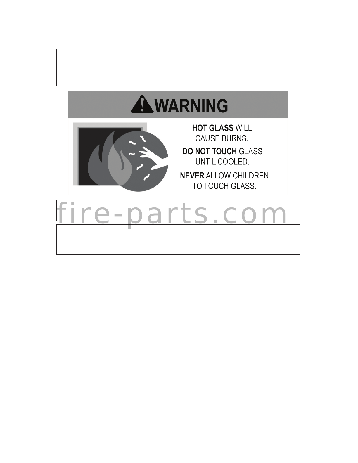
This replace reaches high temperatures. Keep children and adults
away from hot surface to avoid burns or clothing ignition. Fireplace
will remain hot for a time after shutdown. Allow surface to cool
before touching.
Carefully supervise young children when they are in the room with
replace.
Keep area around your replace clear of combustible materials,
gasoline and other ammable vapor or liquids. Do not run replace
where these are used or stored.
1. For propane/LP replace, do not place
propane/LP supply tank(s) inside any
structure. Locate propane/LP supply
tank(s) outdoors. To prevent performance
problems, do not use propane/LP fuel tank
of less than 100 lbs. capacity.
2. If you smell gas
• shut off gas supply
• do not try to light any appliance
• do not touch any electrical switch; do
not use any phone in your building
• immediately call your gas supplier from
a neighbor’s phone. Follow the gas sup-
plier's instructions
• if you cannot reach you gas supplier,
call the re department
3. Never install the replace
• in windy or drafty areas where curtains
or other combustible (ammable) objects
can make contact with the replace front
• in high trafc areas
4. Turn fireplace off and let cool before
servicing, installing or repairing. Only a
qualied service person should install,
service or repair this replace. Have replace inspected annually by a qualied
SAFETY
Continued
service person.
5. You must keep control compartments,
burners and circulating air passages
clean. More frequent cleaning may be
needed due to excessive lint and dust
from carpeting, bedding material, etc.
Turn off the gas valve and pilot light before
cleaning replace.
6. Have venting system inspected annually
by a qualied service person. If needed,
have venting system cleaned or repaired.
7. Do not use any solid fuels (wood, coal,
paper, cardboard, etc.) in this replace.
Use only the gas type indicated on re-
place nameplate.
8. Do not use replace if any part has been
exposed to or under water. Immediately
call a qualied service person to arrange
for replacement of the unit.
9.
Do not operate replace if any log is broken
.
10. Do not operate replace with glass door
removed, cracked or broken.
11. Provide adequate clearances around air
openings.
f i r e - p a r t s . c o m
www.fmiproducts.com
123095-01C6
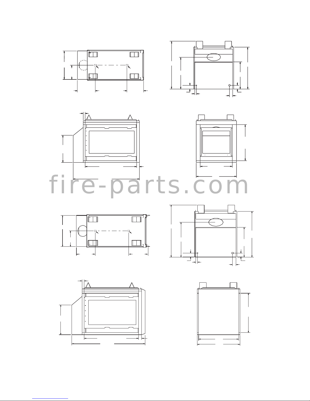
DIMENSIONS
FRONT VIEW
30"
(Opening)
25"
19
7
/8"
(Opening)
RIGHT SIDE
1 7/8"
22
5
/8"
41
1
/8"
32"
(Opening)
1
7
/8"
39
3
/4"
26
3
/8"
3"
1"
3
1
/2"
22
5
/8"
34
3
/4"
3"
BACK VIEW
TOP VIEW
(Left Side)
(Right Side)
(Front)
(Back)
24"
11
15
/
16
101/2"
1
1
/2"ø 11/2"ø
10
1
/2"
FRONT VIEW
30"
(Opening)
24"
25"
RIGHT SIDE
22 5/8"
43
1
/8"
32" (Opening)
1
7
/8"
1
7
/8"
BACK VIEW
39 3/4"
26
3
/8"
3"
1"
2"
3"
22
5
/8"
34
3
/4"
TOP VIEW
(Left Side)
(Right Side)
(Front)
(Back)
24"
11
15
/16"
10
1
/2"
ø1
1
/2"ø11/2"
11
1
/8"
Figure 1 - Peninsula Dimensions
Figure 2 - See-Thru Dimensions
f i r e - p a r t s . c o m
www.fmiproducts.com
123095-01C 7
PRE-INSTALLATION PREPARATION
CLEARANCES
Minimum clearances to combustibles for
replace are as follows:
Back and sides of surround 0"
Vent Surfaces (side and bottom) 1"
Top Vent Surface (horizontal run) 2"
Ceiling to Opening 36"
Floor 0"
Wall to Front of Glass 36"
Perpendicular Wall to Opening of Unit 2"
Top Spacer 0"
NOTICE: This replace is intended for use as supplemental
heat. Use this replace along
with your primary heating system. Do not install this replace
as your primary heat source.
If you have a central heating
system, you may run system’s
circulating blower while using
replace. This will help circulate
the heat throughout the house.
In the event of a power outage,
you can use this replace as a
heat source.
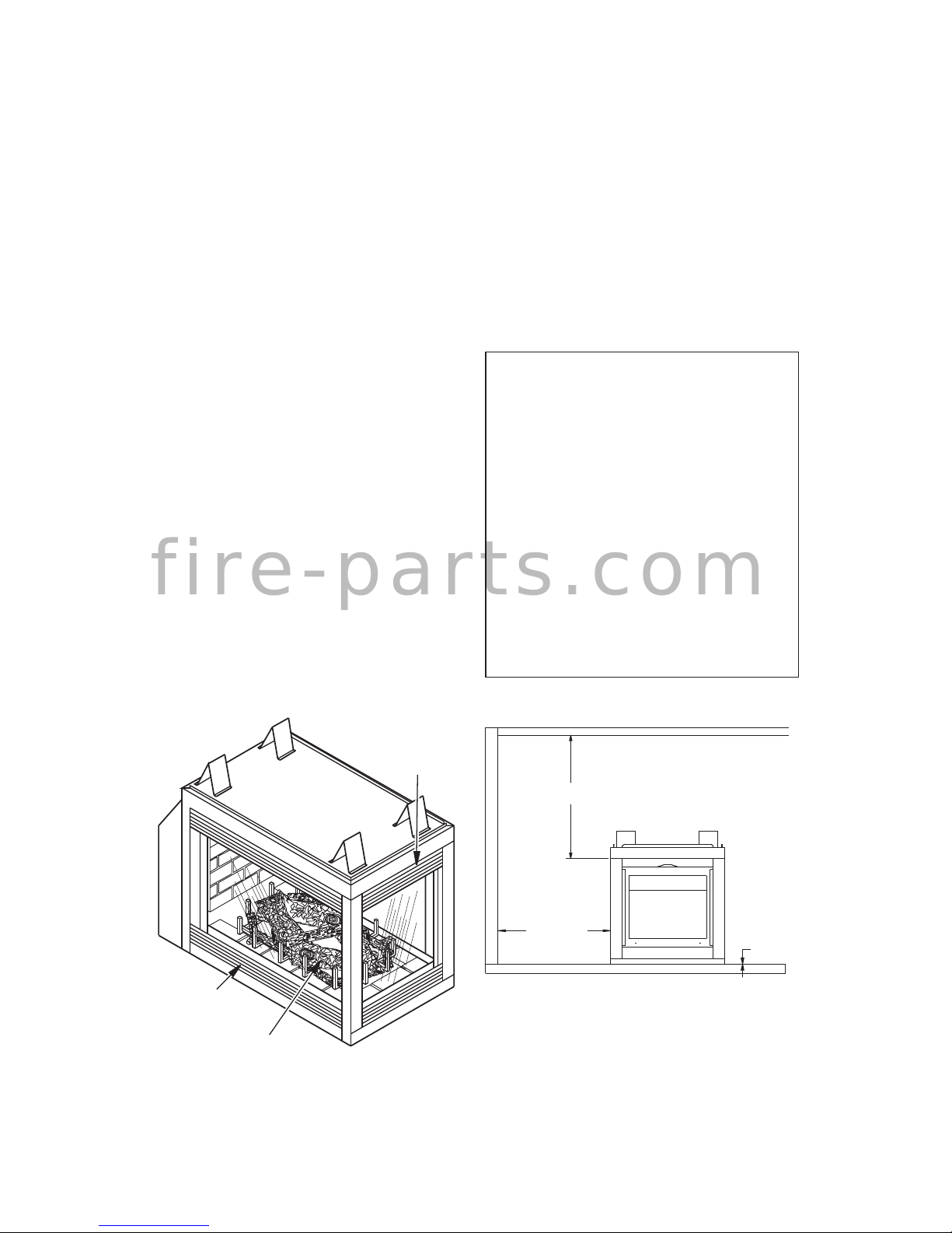
MANTEL CLEARANCES
Figure 3 - Direct-Vent Fireplace
Log Set
Upper
Louver
Panel
Lower
Louver
Panel
Figure 4 - Minimum Clearances
(Peninsula Shown)
CEILING
WALL
36" Min.
36" Min.
0" Floor
LOCATION AND SPACE
REQUIREMENTS
Determine the safest and most efficient
location for your Style Crest, Inc. direct-vent
replace. Make sure that rafters and wall
studs are not in the way of the venting system.
Choose a location where heat output is not
affected by drafts, air conditioning ducts, windows or doors. Be aware of all restrictions and
precautions before deciding the exact location
for your replace and termination cap.
When deciding the location of your replace,
follow these rules:
• A projection may be ideal for a new addition
on an existing nished wall. Refer to horizontal termination congurations on page
16 or vertical congurations on page 19.
• Do not connect fireplace venting to a
chimney ue serving a separate solid-fuel
burning replace or appliance.
• Due to high temperatures, do not locate
replace in high trafc areas, windy or drafty
areas or near furniture or draperies.
• Never obstruct front opening of appliance
or ow of combustion and ventilation air.
Keep control compartments accessible.
• Do not locate close to where gasoline or
other ammable liquids may be stored.
Appliance must be kept clear and free from
combustible materials.
f i r e - p a r t s . c o m
www.fmiproducts.com
123095-01C8
0"
36"
2"
Wall In Front Of Glass
36" Min.
Perpendicular
Wall 2" Min.
From Opening
Right Side
Surround
(0" Min.)
Left Side
Surround
(0" Min.)
TOP VIEW
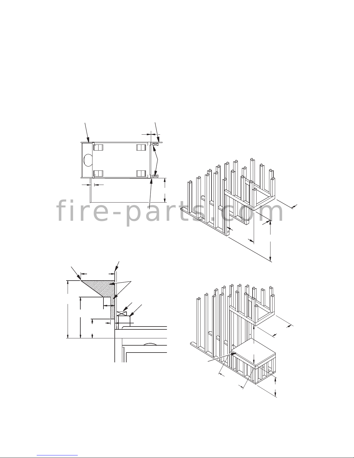
Figure 6 - Mantel Clearances for
Peninsula and See-Thru Fireplaces
(Peninsula Shown)
21" Min.
15" Min.
12" Min.
4"
Min.
7" Min.
1
1
/2" Max.
UNIT
Spacer
2 x 4
Combustible
Material May
Be Used
Drywall (Gypsum
Board, Sheetrock, etc.)
Safe Zone for
Projection of
Combustible
Material
Woodwork, such as wood trims, mantels and
other combustible materials should not be
placed within 7" of the opening of replace
(see Figure 6).
Combustible material above projecting more
than 1 1/2" from appliance’s front face must
not be placed less than 15" from opening
of appliance, (ref. NFPA Standard 211 Sec.
7-3.3.3)
PRE-INSTALLATION PREPARATION
Continued
Figure 5 - Minimum Clearances
(See-Thru Shown)
Combustible Material
Drywall
2 x 4
Stud
Minimum 1" Clearance from
Side (Only for See-Thru)
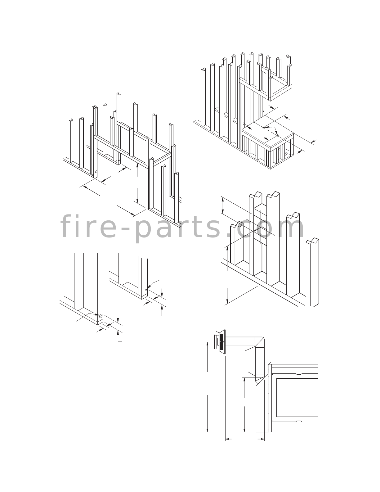
FRAMING
Once nal location has been determined,
observing clearances for vent termination,
you may construct framing using dimensions
shown in Figures 7 thru 13 depending on your
particular installation
If appliance is to be installed directly on carpeting, tile (other than ceramic), or any com-
bustible material other than wood ooring, the
appliance must be installed upon a metal or
wood panel extending the full width and depth
of the appliance. There are three holes on
each side of the bottom of unit where screws
can be used to secure unit to oor.
Figure 7 - Rough Opening for Installing
Peninsula Fireplace
39 3/4" Min.
40
1
/
2
"
23
5
/
8
"
39 3/4"
Min.
40
1
/
2
"
23
5
/
8
"
*
Figure 8 - Rough Opening for Installing
Peninsula Fireplace on Platform
* As required by design as long as
ceiling clearance is maintained.
Platform
Must Be
Solid, Flat,
and Fully
Supported
f i r e - p a r t s . c o m
www.fmiproducts.com
123095-01C 9
PRE-INSTALLATION PREPARATION
Continued
39 3/4"
Min.
43
1
/
4
"
24"
Figure 9 - Rough Opening for Installing
See-Thru Fireplace
3"
1" Dia. Hole
3"
2" Dia. Hole
1"
2"
Figure 10 - Hole Locations For Gas Line
and Electric Wires for Peninsula and
See-Thru Fireplaces
Height
Depends On
Installation
10"
Square Min.
Figure 12 - Rough Opening for Installing
Exterior Vent Terminal
Vertical
Height
Depends on
Installation
26
3
/8"
Horizontal
Length Depends
on Installation
90
o
Elbow
45
o
Elbow
Figure 13 - Vent Opening Height
Figure 11 - Alternate Gas Supply
Location
11
15
/
16
"
10
1
/
2
"
20
3
/
16
"
1
1
/
2
"
The gas supply line may be connected through
side framing or alternately through lower sub-
ooring or a platform base if provided (see
Figures 10 and 11). Depending on installation,
refer to appropriate illustrations.
f i r e - p a r t s . c o m

www.fmiproducts.com
123095-01C10
REQUIREMENTS FOR THE COMMONWEALTH OF
MASSACHUSETTS
For all side wall horizontally vented gas fueled
equipment installed in every dwelling, building or
structure used in whole or in part for residential
purposes, including those owned or operated by
the Commonwealth and where the side wall exhaust vent termination is less than seven (7) feet
above nished grade in the area of the venting,
including but not limited to decks and porches,
the following requirements shall be satised:
INSTALLATION OF CARBON
MONOXIDE DETECTORS
At the time of installation of the side wall horizontal vented gas fueled equipment, the installing
plumber or gas tter shall observe that a hard
wired carbon monoxide detector with an alarm
and battery backup is installed on the oor level
where the gas equipment is to be installed. In
addition, the installing plumber or gas tter shall
observe that a battery operated or hard wired carbon monoxide detector with an alarm is installed
on each additional level of the dwelling, building or
structure served by the side wall horizontal vented
gas fueled equipment. It shall be the responsibility
of the property owner to secure the services of
qualied licensed professionals for the installation
of hard wired carbon monoxide detectors.
In the event that the side wall horizontally
vented gas fueled equipment is installed
in a crawl space or an attic, the hard wired
carbon monoxide detector with alarm and
battery back-up may be installed on the next
adjacent oor level.
In the event that the requirements of this
subdivision can not be met at the time of
completion of installation, the owner shall
have a period of thirty (30) days to comply with
the above requirements; provided, however,
that during said thirty (30) day period, a battery
operated carbon monoxide detector with an
alarm shall be installed.
Approved Carbon Monoxide Detectors
Each carbon monoxide detector as required
in accordance with the above provisions shall
comply with NFPA 720 and be ANSI/UL 2034
listed and IAS certied.
SIGNAGE
A metal or plastic identication plate shall be
permanently mounted to the exterior of the
building at a minimum height of eight (8) feet
above grade directly in line with the exhaust
vent terminal for the horizontally vented gas
fueled heating appliance or equipment. The
sign shall read, in print size no less than 1/2" in
size, "GAS VENT DIRECTLY BELOW. KEEP
CLEAR OF ALL OBSTRUCTIONS".
INSPECTION
The state or local gas inspector of the side
wall horizontally vented gas fueled equipment
shall not approve the installation unless, upon
inspection, the inspector observes carbon
monoxide detectors and signage installed in
accordance with the provisions of 248 CMR
5.08(2)(a) 1 through 4.
EXEMPTIONS: The following equipment is
exempt from 248 CMR 5.08(2)(a) 1 through 4:
• The equipment listed in Chapter 10 entitled
"Equipment Not Required To Be Vented"
in the most current edition of NFPA 54 as
adopted by the Board; and
• Product Approved side wall horizontally
vented gas fueled equipment installed in a
room or structure separate from the dwelling, building or structure used in whole or
in part for residential purposes.
MANUFACTURER REQUIREMENTS
Gas Equipment Venting System Provided
When the manufacturer of Product Approved
side wall horizontally vented gas equipment
provides a venting system design or venting
system components with the equipment, the
instructions provided by the manufacturer for
installation of the equipment and the venting
system shall include:
• Detailed instructions for the installation of
the venting system design or the venting
system components; and
• A complete parts list for the venting system
design or venting system.
Gas Equipment Venting System Not
Provided
When the manufacturer of a Product Approved side wall horizontally vented gas fueled equipment does not provide the parts for
venting the ue gases, but identies "special
venting systems", the following requirements
shall be satised by the manufacturer:
•
The referenced "special venting system" instructions shall be included with the appliance
or equipment installation instructions; and
• The "special venting systems" shall be Prod-
uct Approved by the Board, and the instructions for that system shall include a parts list
and detailed installation instructions.
A copy of all installation instructions for all
Product Approved side wall horizontally
vented gas fueled equipment, all venting instructions, all parts lists for venting instructions, and/or all venting design instructions
shall remain with the appliance or equipment
at the completion of the installation.
f i r e - p a r t s . c o m

www.fmiproducts.com
123095-01C 11
GENERAL VENTING
• If using a venting conguration of only
horizontal venting with no vertical run, a
1/4" rise for every 12" of run toward the
termination is required.
• There must not be any obstruction such
as bushes, garden sheds, fences, decks,
or utility buildings within 24" from the front
of the termination cap.
• Do not locate termination cap where excessive snow or ice build up may occur. Be
sure to clear vent termination area after
snow falls to prevent accidental blockage of
venting system. When using snow blowers,
do not direct snow towards vent termination
area.
VENT TERMINATION CLEARANCES
The nal position of your appliance depends
on the location of the vent termination in relation to the clearances that must be observed
as shown in Figure 14, page 12.
You may avoid extra framing by positioning
your replace against an already existing
framing member. The back of the replace
may be positioned directly against a combustible wall.
Check with local codes. In the USA, follow the
current National Fuel Gas Fuel Gas Code,
ANS Z223.1 also known as NFPA 54.
These models are approved for use with
Style Crest, Inc. Series, rigid type direct vent
pipe as supplied by Style Crest, Inc. or with
approved types of exible vent pipe (not supplied) when appropriate sized for an 8" outer
and 5" inner diameter application.
Your replace is approved to be vented either
through the side wall, or vertically using the
following guidelines:
• Only use Style Crest, Inc. supplied or
approved types of venting components
or kits. Do not mix different types of vent
components, modify vent components or
custom fabricate vent components for use
in any one installation.
• Minimum clearance between vent pipes
and combustible materials is 1", except
where stated otherwise.
• Combustible material may be ush with
the top front of replace with a maximum
thickness of 3/4".
• Do not recess venting terminals into a wall
or siding.
• Do not install vent terminals below grade
level. Maintain a minimum height of 12"
above snow line.
• Do not terminate venting system into an
attic or garage.
f i r e - p a r t s . c o m
 Loading...