

Vexar CD32M-B Owner's Operation And Installation Manual

DIRECT VENT FIREPLACE
OWNER’S OPERATION AND INSTALLATION MANUAL
O-TL REPORT # 114-F-06-5
MODEL CD32M-B
WARNING: If the information in this manual is not
followed exactly, a re or explosion may result causing
property damage, personal injury or loss of life.
— Do not store or use gasoline or other ammable
vapors and liquids in the vicinity of this or any other
appliance.
— WHAT TO DO IF YOU SMELL GAS
• Do not try to light any appliance.
• Do not touch any electrical switch; do not use any
phone in your building.
• Immediately call your gas supplier from a neighbor’s
phone. Follow the gas supplier’s instructions.
• If you cannot reach your gas supplier, call the re
department.
— Installation and service must be performed by a quali-
ed installer, service agency or the gas supplier.
INSTALLER: Leave this manual with the appliance.
CONSUMER: Retain this manual for future reference.
For more information, visit www.desatech.com
Introduction .......................................................... 3
Selecting Location ............................................... 3
Safety .................................................................. 4
Local Codes......................................................... 5
Product Features ................................................. 6
Pre-Installation Preparation .................................. 6
Installation ........................................................... 9
Burner Flame Adjustment .................................. 23
Operation ........................................................... 24
SAVE THIS BOOK
This book is valuable. In addition to instructing you on how to install and
maintain your appliance, it also contains information that will enable you to
obtain replacement parts or optional accessory items when needed. Keep
it with your other important papers.
WARNING: Improper installation, adjustment, al-
Gas Conversion ................................................. 26
Specications .................................................... 27
Troubleshooting ................................................. 28
Replacement Parts ............................................ 29
Service Hints ..................................................... 29
Technical Service............................................... 29
Accessories ....................................................... 29
Parts .................................................................. 30
Limited Two Year Warranty ..................Back Cover
teration, service or maintenance can cause injury or
property damage. Refer to this manual for correct installation and operational procedures. For assistance
or additional information consult a qualied installer,
service agency or the gas supplier.
TABLE OF CONTENTS
WARNING: This direct vent gas replace is intended
for use with natural or propane/LP gas only. Do not attempt to burn any solid fuels in this appliance.
This replace is manufactured for Stylecrest Inc. under
the Vexar brand name by DESA Heating, LLC.
This replace may be installed as an OEM installation
in a manufactured (mobile) home and must be installed
in accordance with the manufacturers instructions and
the Manufactured Home Construction and Safety Stan-
dard, Title 24 CFR, Part 3280 in the United States or the
Mobile Home Standard, CAN/CSA Z240 MH Series, in
Canada. This replace is only for use with the type(s)
of gas indicated on the rating plate. A conversion kit is
supplied with the replace.
www.desatech.com
124433-01A2
INTRODUCTION
WARNING: This product contains and/or generates chemicals
known to the State of California
to cause cancer or birth defects
or other reproductive harm.
Models CD32M-B is a heat circulating gravity
direct vent replaces with sealed combustion
chamber. These replaces use millivolt gas
control valve and millivolt ignition system.
These fireplaces are convertible with the
standard setup as natural gas. Conversion
may be performed by the OEM mobile home
builder or by a qualied service person on-
site. If you are uncertain as to what gas your
unit is equipped for, please check the rating
plate located inside of the appliance opening
or consult your mobile home supplier or your
local distributor of Style Crest, Inc. products.
NOTICE: Check local building
codes for area requirements before installing this appliance.
BEFORE YOU BEGIN
Before beginning the installation of your
appliance, read these instructions through
completely.
This Style Crest, Inc. replace and its components are safe when installed according
to this installation manual and operated as
recommended. Unless you use Style Crest,
Inc. components designed and tested for
this replace system, YOU MAY CAUSE A
SAFETY HAZARD!
The Style Crest, Inc. warranty will be voided
by, and Style Crest, Inc. disclaims any responsibility for the following actions:
A) Modication to the replace, components,
doors, blower, fans or vent system.
B) Use of any component part not manu-
factured or approved by Style Crest, Inc.
in combination with a Style Crest, Inc.
replace system.
Proper installation is the most important step
in ensuring safe and continuous operation
of the replace. Consult the local building
codes as to the part icular require ments
concerned with the installation of all factory
built replaces. This replace, when installed,
must be electrically grounded in accordance
with local codes or in the absence of local
codes, with the National Electrical Code,
ANSI/NFPA 70.
The installation must conform with local codes
or, in the absence of local codes, with the
National Fuel Gas Code, ANSI Z223.1. This
appliance complies with ANSI Z21.88.
SELECTING LOCATION
To determine the safest and most efcient
location for your replace, consider the fol-
lowing guidelines:
1. The location must allow for proper clearances (see Figure 1).
• Flush installation is recommended where
living space is limited.
• Projected installation may be ideal for
a new addition to an existing nished
wall.
• Corner installation makes use of a space
that may not normally be used and pro-
vides a wider and more efcient range
for radiant heat transfer.
2. Consider a location where the replace
would not be affected by drafts, air conditioning ducts, windows or doors.
124433-01A 3
www.desatech.com
3. A location that avoids the cutting of joists
or roof rafters makes ventilation installation easier.
FULL
PROJECTION
Figure 1 - Common Fireplace Locations
CORNER
INSTALLATION
FLUSH
INSTALLATION
SELECTING LOCATION
Continued
In selecting a location, the following precautions must be observed:
• Do not connect this appliance to a chimney system used for solid fuel burning
replace.
• Due to high temperatures, do not locate
this appliance in high trafc areas or near
furniture and draperies.
• Never obstruct openings of the appliance or
ow of ventilation air. Keep control compart-
ments accessible.
SAFETY
• Do not locate appliance close to where
gasoline or other ammable liquids may be
stored. The appliance must be kept clear
and free from combustible materials.
• Do not use this appliance if any part has
been under water. Immediately contact a
local service technician to examine the
appliance and to replace any part(s) of the
control ignition system and other related
components that have been submerged
under water.
DANGER: Carbon monoxide
poisoning may lead to death!
This replace must be installed by the O.E.M.
builder or by a qualied (certied or licensed)
service person. It has a sealed gas combustion chamber that uses a coaxial pipe (pipe
within a pipe and having the same center)
venting system. It brings in fresh air for combustion through the outer pipe and combustion gases are exhausted through the inner
pipe. If the glass door assembly and venting
pipe are not properly seated, connected and
sealed, carbon monoxide leakage (spillage)
can occur.
Carbon Monoxide Poisoning: Early signs
of carbon monoxide poisoning resemble the
u, with headaches, dizziness or nausea. If
you have these signs, the replace may not
be working properly. Get fresh air at once!
Have replace serviced. Some people are
more affected by carbon monoxide than others. These include pregnant women, people
with heart or lung disease or anemia, those
under the inuence of alcohol and those at
high altitudes.
Propane/LP and Natural Gas: Propane/LP
and natural gas are odorless. An odor-making
agent is added to the gas. The odor helps you
detect a gas leak. However, the odor added to
the gas can fade. Gas may be present even
though no odor exists.
Make certain you read and understand all
warnings. Keep this manual for reference. It
is your guide to safe and proper operation of
this replace.
WARNING: Any change to
this replace or it’s controls can
be dangerous. Do not modify
this replace under any circumstances. Any parts removed for
servicing must be replaced prior
to operating replace.
WARNING: Do not use a blower insert, heat exchanger insert
or other accessory not approved
for use with this replace.
WARNING: This appliance
is only for use with the type of
gas indicated on the rating plate.
This appliance is not convertible
for use with other gases unless
a certied kit is used.
WARNING: Do not allow fans
to blow directly into the replace.
Avoid any drafts that alter burner
ame patterns.
Due to high temperatures, the
appliance should be located out
of trafc and away from furniture
and draperies.
www.desatech.com
124433-01A4
SAFETY
Continued
Do not place clothing or other
ammable material on or near
the appliance. Never place any
objects on the appliance.
Do not use this replace to cook
food or burn paper or other ammable material.
This replace reaches high temperatures. Keep children and
adults away from hot surface to
avoid burns or clothing ignition.
Fireplace will remain hot for a
time after shutdown. Allow surface to cool before touching.
Carefully supervise young chil-
dren when they are in the room
with replace.
Keep the area around your
replace clear of combustible
materials, gasoline and other
ammable vapor or liquids. Do
not run replace where these
are used or stored.
1. For propane/LP replace, do not place
propane/LP supply tank(s) inside any
structure. Locate propan e/LP supp ly
tank(s) outdoors. To prevent performance
problems, do not use propane/LP fuel tank
of less than 100 lbs. capacity.
2. If you smell gas
• shut off gas supply
• do not try to light any appliance
• do not touch any electrical switch; do not
use any phone in your building
• immediately call your gas supplier from
a neighbor’s phone. Follow the gas supplier's instructions
• if you cannot reach you gas supplier, call
the re department.
3. Never install the replace
• in a recreational vehicle
• in windy or drafty areas where curtains or
other combustible (ammable) objects can
make contact with the replace front
• in high trafc areas
4. Turn fireplace off and let cool before
servicing, installing or repairing. Only a
qualied service person should install,
service or repair this replace. Have replace inspected annually by a qualied
service person.
5. You must keep control compartments,
burners and circulating air passages
clean. More frequent cleaning may be
needed due to excessive lint and dust
from carpeting, bedding material, etc.
Turn off the gas valve and pilot light before
cleaning replace.
6. Have venting system inspected annually by
a qualied service person. If needed, have
venting system cleaned or repaired.
7. Do not use any solid fuels (wood, coal,
paper, cardboard, etc.) in this replace.
Use only the gas type indicated on re-
place nameplate.
8. This appliance, when installed, must be
electrically grounded in accordance with
local codes or, in the absence of local
codes, with the National Electrical Code,
ANSI/NFPA 70.
9. Do not use replace if any part has been
exposed to or under water. Immediately
call a qualied service person to arrange
for replacement of the unit.
10. Do not operate replace if any log is
broken.
11. Do not operate replace with glass door
removed, cracked or broken.
12. Provide adequate clearances around air
openings.
LOCAL CODES
Install and use replace with care. Follow all
local codes. In the absence to local codes,
use the current National Fuel Gas Code ANSI
Z223.1/NFPA 54* (USA) or the current CSAB149.1 Installation Code (Canada).
*Available from:
American National Standards Institute, Inc.
1430 Broadway
New York, NY 10018
National Fire Protection Association, Inc.
Batterymarch Park
Quincy, MA 02269
124433-01A 5
www.desatech.com
PRODUCT FEATURES
C
B
A
D
E
F
G
T o p of Louver Opening
3
2
1
4
5
6
7
Wa ll
These are a few facts that can help you under-
stand and enjoy your direct-vent replace:
• The venting system may be routed to the
outside of your home in several ways. It
may vent through the roof (vertical) or it
may vent to an outside/exterior wall (hori-
zontal). The vent pipe installation is very
important to allow for proper operation.
You must follow the venting instructions
very carefully for either vertical or horizontal
applications.
• This replace may be installed in any room
of your house provided all local codes and
these installation instructions are followed.
• A piezo ignitor and ceramic electrode create spark to ignite the pilot light. It does not
require any matches, batteries or any other
sources of ignition to light the pilot.
• Each time you turn on your replace, you
PRE-INSTALLATION PREPARATION
CAUTION: Do not block
required air spaces with insulation or any other material. Do not
obstruct the effective opening
of the appliance with any type
of facing material.
CLEARANCES TO COMBUSTIBLES
Minimum clearances to combustibles for the
replace are:
• Back and Sides of Fireplace . . . . . . . . 0"
• Floor . . . . . . . . . . . . . . . . . . . . . . . . . . 0"
• Perpendicular Wall . . . . . . . . . . . . . . . 6"
• Front . . . . . . . . . . . . . . . . . . . . . . . . . 36"
• Top of Standoffs .................. 0"
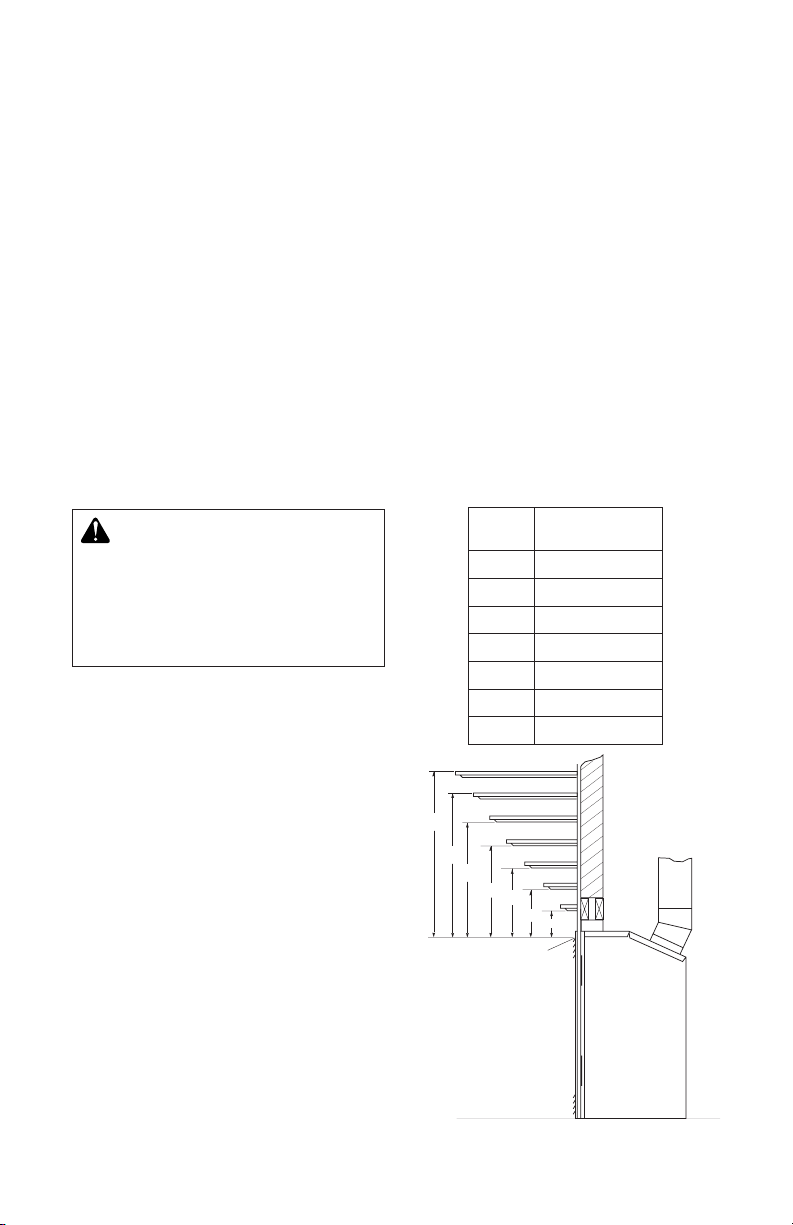
MANTEL CLEARANCES
Woodwork, such as wood trims, mantles
and other combustible materials should be
placed within the required clearance speci-
ed in Figure 2.
may notice some amount of condensation
on the inside of the replace glass. This
is normal and will disappear after 10-20
minutes of operation.
• Your d irect-vent gas firepla ce system
(replace and venting) is a balanced and
sealed gas operating unit. It requires approximately 10-20 minutes of operating
time before the ame pattern stabilizes.
• This replace is equipped with a millivolt
gas control system that does not require
electricity to operate. A piezo ignitor is
provided to light the pilot without using
matches or lighters.
• This model can accept an optional circulating air blower when 120 VAC connection is
supplied. If you plan to install an optional
blower, do not forget to wire the replace
outlet when framing.
Mantel
Depth
Mantel From Top
of Opening
(1) 14" (A) 16"
(2) 12" (B) 14"
(3) 10" (C) 12"
(4) 8" (D) 10"
(5) 6" (E) 8"
(6) 4" (F) 6"
(7) 2" (G) 4"
Figure 2 - Mantel Clearances
www.desatech.com
124433-01A6
PRE-INSTALLATION PREPARATION
A
B
E
F
G
H
D
C
Nailing Tabs
Continued
VENT TERMINATION CLEARANCES
Final position of your replace depends on
location of the vent termination in relation to
clearances that must be observed as shown
in Figure 5 on page 8.
The vent system serves as the “chimney” as
well as combustion air supply (air intake).
The horizontal run must have a rise of 1/4"
(0.6 cm) for every 12" (30.48 cm) of horizon-
tal run towards the termination. Maximum
horizontal run depends on vertical rise from
replace adapter collar to vent termination
(see table below).
VERTICAL HORIZONTAL
0 to 1 ft (30.48 cm)
1 ft (30.48 cm) to 4 ft (121.92 cm)
2 ft (60.96 cm) to 8 ft (243.84 cm)
3 ft (91.44 cm) to 12 ft (365.76 cm)
4 ft (121.92 cm) to 16 ft (487.68 cm)
5 ft (152.40 cm) to 15 ft (457.20 cm)
6 ft (182.88 cm) to 14 ft (426.72 cm)
7 ft (213.36 cm) to 13 ft (396.24 cm)
8 ft (243.84 cm) to 12 ft (365.76 cm)
WARNING: Never allow the
vent to run downward as this
may cause excessive temperatures which could cause a re.
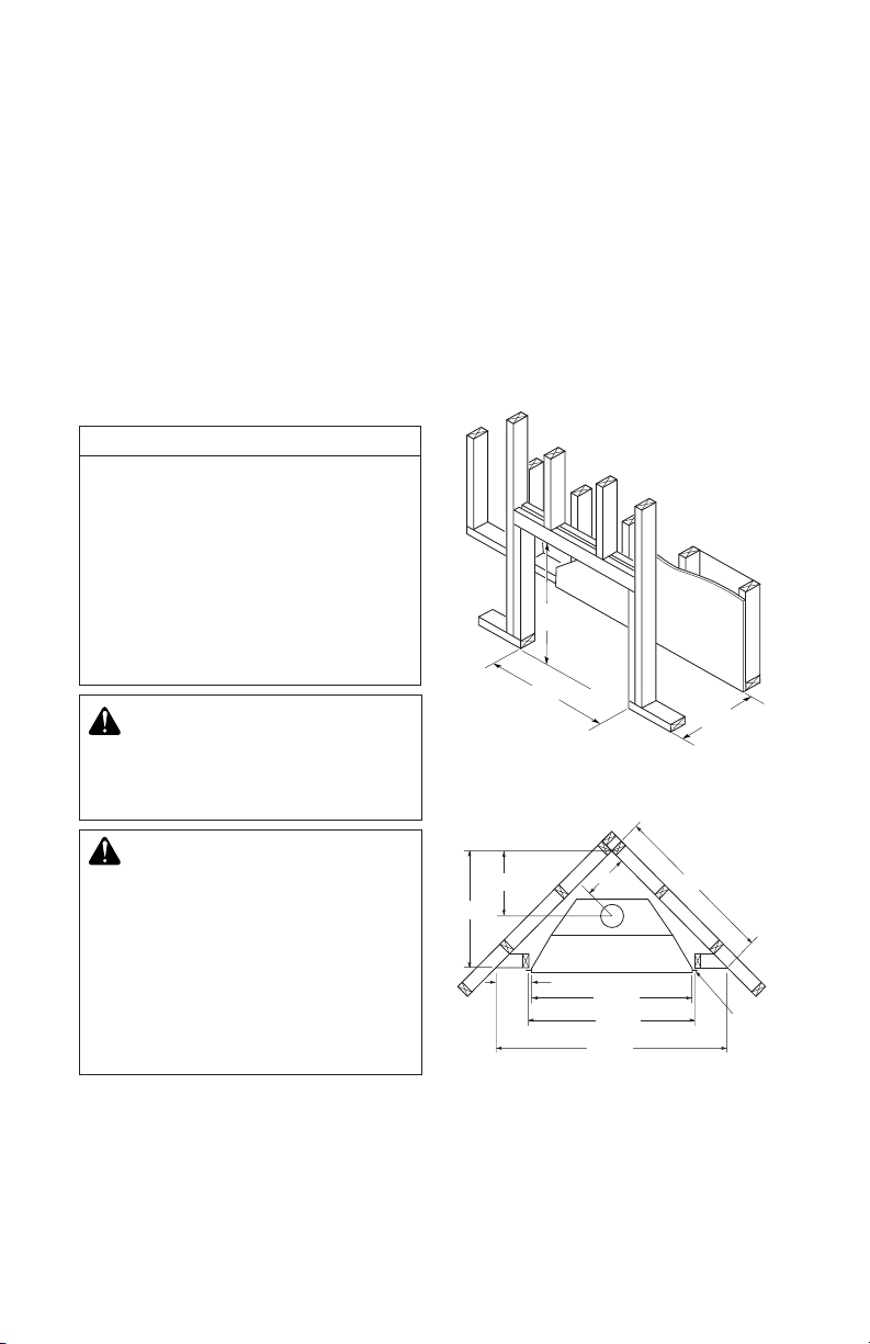
FRAMING
Once the nal location has been determined,
observing height clearances for vent termination, you may construct framing using dimensions shown in Figures 3 and 4, depending on
your installation.
If the appliance is to be installed directly on
carpeting, tile (other than ceramic) or any
combustible material other than wood ooring, appliance must be installed on a metal
or wood panel extending full width and depth
of the appliance.
323/8"
345/8"
19"
Figure 3 - Framing Dimension
WARNING: Horizontal sec-
tions of this vent system require
a minimum clearance of 2" from
28 1/2"
13 5/8"
9 1/2"
39 3/8"
the top of the pipe and 1" minimum to the sides and bottom.
Vertical sections of this system
require a minimum of 1" clearance to combustible materials
on all sides of the pipe.
124433-01A 7
www.desatech.com
97/8"
343/8"
345/8"
541/8"
Figure 4 - Corner Installation
Nailing
Tabs

Fixed
Closed
Openable
Fixed
Closed
V
V
V
V
V
V
V
V
X
X
V
X
G
G
J
F
B
B
K
N
H
I
A
N
E
L
D
B
M
A
C
B
V
V
A
G
G
B
TERMINATION CAP
AIR SUPPLY INLET
GAS METERRESTRICTED AREA
(TERMINATION PROHIBITED)
A = clearance above grade, veranda, porch, deck, or
balcony [*12" (30.5 cm) minimum]
B = clearance to window or door that may be opened
[6" (15 cm) min. for 10,000 Btu or less; 9" (23 cm) in US
if between 10,000 and 50,000, 12" (30 cm) in Canada
if between 10,000 and 100,000; 12" (30 cm) in US if
greater than 50,000, 36" (91 cm) in Canada if greater
than 100,000]
C = clearance to permanently closed window
[minimum 12" (30.5 cm) recommended to prevent
condensation on window]
D = vertical clearance to ventilated soffit located above the
terminal within a horizontal distance of 24" (61 cm) from
the center-line of the terminal [18" (45.7 cm) minimum]
E = clearance to unventilated soffit [12" (30.5 cm) minimum]
F = clearance to outside corner (see below)
G = clearance to inside corner (see below)
H = *not to be installed above a meter/regulator assembly
within 36" (91.4 cm) horizontally from the center line
of the regulator
I = clearance to service regulator vent outlet [*72" (182.9 cm)
minimum]
J = clearance to non-mechanical air supply inlet to building
or the combustion air inlet to any other fireplace
[6" (15 cm) min. for 10,000 Btu or less; 9" (23 cm) in US
if between 10,000 and 50,000, 12" (30 cm) in Canada
if between 10,000 and 100,000; 12" (30 cm) in US if
greater than 50,000, 36" (91 cm) in Canada if greater
than 100,000]
K = clearance to a mechanical air supply inlet [*In Canada,
6 ft. (1.83m) minimum; In US 3 ft. (91 cm) above if within
10 ft. (3 m) horizontally]
L = † clearance above paved side-walk or a paved driveway
located on public property [*84" (213.3 cm) minimum]
M = clearance under veranda, porch, deck
[*12" (30.5 cm) minimum ‡]
N = clearance above a roof shall extend a minimum of
24" (61 cm) above the highest point when it passes
through the roof surface and any other obstruction within
a horizontal distance of 18" (45.7 cm)
† vent shall not terminate directly above a side-walk or paved driveway which is located between two
single family dwellings and serves both dwellings*
‡ only permitted if veranda, porch, deck or balconey is fully open on a minimum of 2 sides beneath the floor*
* as specified in CAN/CSA B149 (.1 or .2) Installation Codes (1991) for Canada and U.S.A.
Note: Local codes or regulations may require different clearances
A = 6" (15.2 cm)
Inside Corner
V
B
E
V
B = 6" (15.2 cm)
C = Maximum depth of 48" (121.9 cm)
for recessed location
D = Minimum width for back wall of
recessed location Combustible - 38" (965 mm)
Noncombustible - 24" (61 cm)
E = Clearance from corner in
recessed location Combustible - 6" (15.2 cm)
Noncombustible - 2" (5.1 cm)
Outside Corner Recessed Location
G
H
G = 12" (30.5 cm) minimum clearance
Balcony with No Side Wall
V
J
Combustible &
Noncombustible
H = 24" (61 cm)
J = 20" (50.8 cm)
Balcony with Perpendicular Side Wall
C
D
C
Termination Clearances for Buildings with Combustible and Noncombustible Exteriors
Openable
PRE-INSTALLATION PREPARATION
Continued
Figure 5 - Minimum Clearances for Vent Terminations
www.desatech.com
124433-01A8
INSTALLATION
WARNING: Read all instruc-
tions completely and thoroughly
before attempting installation.
Failure to do so could result in
serious injury, property damage or loss of life. Operation of
improperly installed and maintained venting system could
result in serious injury, property
damage or loss of life.
NOTICE: Failure to follow these in-
structions will void the warranty.
VENTING INSTALLATION
PRECAUTIONS
Consult local building codes before beginning
installation. Installer must make sure to select
proper vent system for installation. Before
installing vent kit, installer must read this replace manual and vent kit instructions.
Only a qualied service person should install
venting system. The installer must follow
these safety rules:
• Wear gl oves an d s afety glasse s f or
protection
• Use extreme caution when using ladders
or when on roof tops
• Be aware of electrical wiring locations in
walls and ceilings
The following actions will void the warranty
on your venting system:
• Installation of any damaged venting component
• Unauthorized modification of the venting
system
• Installation of any component part not
manufactured or approved for use with the
replace.
• Installation other than as instructed by
these instructions
NOTICE: All Style Crest, Inc.
direct vent replaces only approved 5/8" pipe components
and terminations.
WARNING: This gas replace
and vent assembly must be
vented directly to the outside. The
venting system must NEVER be
attached to a chimney serving a
separate solid fuel burning appliance. Each gas appliance must
use a separate vent system. Do
not use common vent systems.
WARNING: Horizontal sec-
tions of this vent system require
a minimum clearance of 2" from
the top of the pipe and 1" minimum to the sides and bottom.
Vertical sections of this system
require a minimum of 1" clearance to combustible materials
on all sides of the pipe.
VENTING INSTALLATION
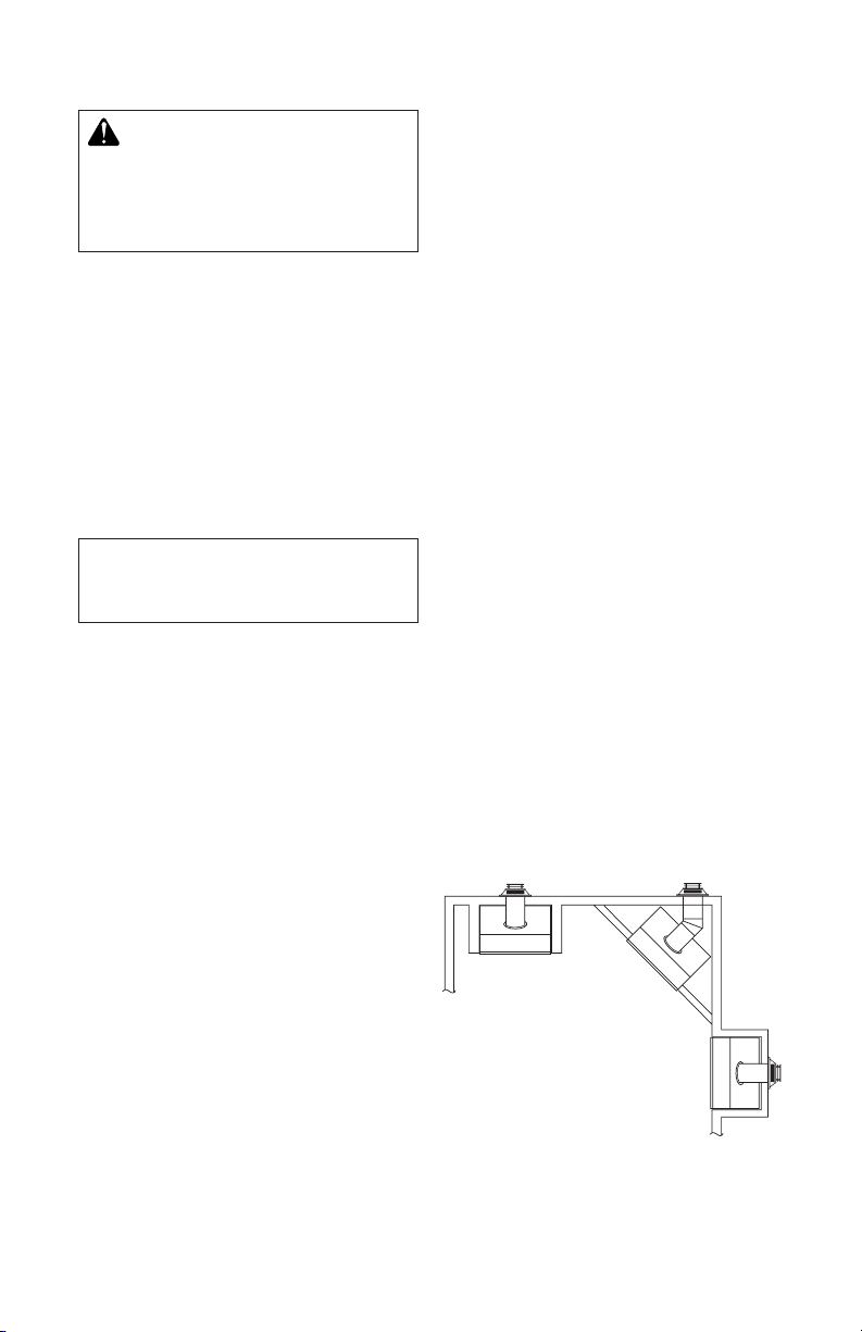
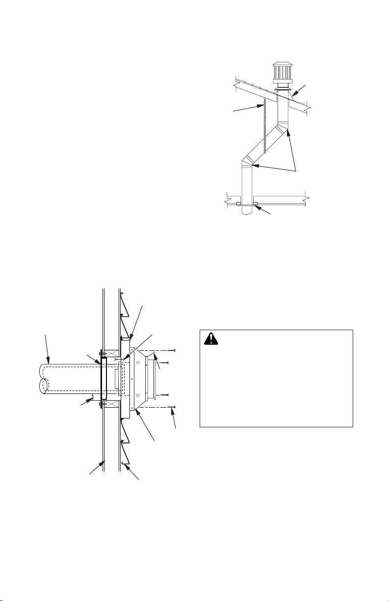
1. Install elbow to replace collar adapter
located on back of the unit at a 45° angle.
Slide elbow over collar and twist to lock.
Check to insure proper connection (see
Figure 6).
2. Continue to install remainder of pipe for
desired installation. Make sure each section is twist-locked securely.
3. When installation of vent pipe is complete,
in stall vent termination. Depending on
location of your replace, you will vent
vertically or horizontally.
4. Allow 1" of pipe to protrude from internal
wall, depending on wall thickness. See
Figure 7, page 10.
Female
Locking
Lugs
Vertical Flue
Restrictor
(For Vertical
Venting
Application)
Male Locking
Lugs
Figure 6 - Venting Installation
124433-01A 9
www.desatech.com
INSTALLATION
Continued
5. For horizontal installation, an optional
siding standoff may be installed between
vent cap and exterior wall. Secure horizontal vent cap to standoff. Secure standoff/
vent cap assembly to wall (see Figure 7).
Do not seal termination to vent pipe. Vent
termination must be removable for service
pipe inspection.
6. For vertical installation, a vertical termination is available. A vertical ue restrictor must be installed into inner collar of
replace as shown in Figure 6, page 9.
When installing a length of pipe for vertical
termination that is over 3 ft., support pipe
every 3 ft. using metal wall straps. Vertical
to horizontal pipe must be kept at a 1 ft. to
4 ft. ratio with a maximum run of no more
than 20 ft.
If an offset is necessary in attic to avoid
obstruction, it is important to support vent
pipe every 3 ft. to avoid excessive stress
on elbows and possible separation (see
Figure 8).
Siding Standoff
(Optional)
Direct vent
Pipe
Wall Firestop
Maintain 1"
Minimum
Air Space
Around Outer
Pipe when
Penetrating a
Wall
10 3/4" x 10 3/4"
Framed Opening
Figure 7 - Vent Termination (Horizontal)
Minimum Pipe
Overlap 1 1/4"
Deector
Shield
Screws
Horizontal
Termination
(Vent Cap)
Exterior Wall
with Vinyl
Siding
Roof
Flashing
Wall
Strap
45° Elbows
Ceiling Firestop
Figure 8 - Vertical Termination with
Offset and Wall Strap
Horizontal Termination Congurations
Figures 9 through 13, page 11 show different
congurations and alternatives for venting
with hor izont al termin ation. Each figure
includes a chart with critical minimum and
maximum dimensions which MUST be met.
IMPORTANT: Remember that a horizontal
run of venting must have a 1/4" rise for every
12" of run toward termination.
WARNING: Never run vent
downward as this may cause
excessive temperatures which
could cause a re. Operation of
improperly installed and maintained venting system could
result in serious injury, property
damage or loss of life.
www.desatech.com
124433-01A10
 Loading...