

Vexar C36EMW-RB, C36EMW-RBB, C36EMW-RPLB Owners & Installation Manual
36" CIRCULATING LOUVERED FIREBOX
OWNER’S INSTALLATION MANUAL
C36EMW-RB with Brushed
Brass Finish Bi-fold Doors
C36EMW-RBB with Black
Finish Bi-fold Doors
C36EMW-RPLB with Platinum
Finish Bi-fold Doors
O-TL REPORT # 114-F-20-4
Includes Manual
Control Fan System
and Combustion
Air Kit
SAVE THIS BOOK
This book is valuable. In addition to instructing you
on how to install and maintain your appliance, it also
contains information that will enable you to obtain replacement parts or accessory items when needed. Keep
it with your other important papers.
This replace is approved for use as a wood burning
replace or for use with a vented gas log approved to
ANS Z21.60, Z21.84 or RGA 2-72 standards or for use
with a vent-free gas log heater approved to ANS Z21.11.2
standard. A vent-free log can only be installed in an aftermarket (completion of sale, not for purpose of resale
from the manufacturer), permanently located, manufactured (mobile) home, where not prohibited by local
codes. Approved hood must be installed when using a
vent-free gas log heater (see Accessories, page 18).
This rebox meets the construction and safety standards of H.U.D. for application in mobile homes when
installed according to these instructions.
INSTALLER: Leave this manual with the appliance.
CONSUMER: Retain this manual for future reference.
For more information, visit www.desatech.com
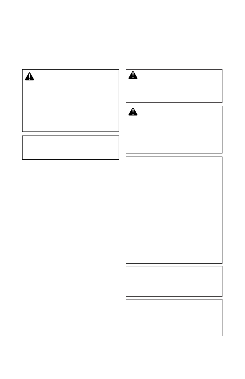
TABLE OF CONTENTS
Safety .................................................................. 2
Specications ...................................................... 3
Fireplace Installation............................................ 3
Venting Installation .............................................. 6
Optional Gas Line Installation............................ 13
SAFETY
Finishing Fireplace ............................................ 15
Operation and Maintenance Guidelines ............ 15
Replacement Parts ............................................ 17
Technical Service............................................... 17
Accessories ....................................................... 18
WARNING: Improper installation, adjustment, alteration,
service or maintenance can
cause injury, property damage or
loss of life. Refer to this manual
for assistance or additional in-
formation. Consult a qualied
installer or local distributor.
IMPORTANT: Check HUD requirements before installing this
replace.
The C36EMW Series is specically designed
for use in manufactured mobile homes. These
replaces include a manual control fan system, combustion air kit and bi-fold doors.
Before beginning the ins talla tion of the
fireplace, read these instructions through
completely.
• This Style Crest replace and its components are safe when installed according
to this installation manual. Unless you use
Style Crest approved components, which
have been designed and tested for the
replace system, you may cause a re
hazard.
• The Style Crest warranty will be voided by
and Style Crest disclaims any responsibility for the following actions.
a. Modication of the replace, compo-
nents, doors, blower, fans, air inlet
system and damper control.
b. Use of any component part not manu-
factured or approved by Style Crest
in combination with a Style Crest
replace system.
Proper installation is the most important step
in ensuring safe and continuous operation of
the replace. Consult the local building codes
as to the particular requirements concerned
with the installation of all factory built replaces. Although grounding may not be required
by code, the manufacturer recommends it.
CAUTION: The structural
integrity of the mobile home
oor and ceiling/roof must be
maintained.
WARNING: Do not install a
replace insert in this box unless
the manufacturer's instructions
with the insert specically state
this replace has been tested for
use with the insert.
FOR YOUR SAFETY
• Do not store or use gasoline
or any other ammable vapors
or liquids in the vicinity of this
or any other appliance.
• Due to high temperatures, the
appliance should be located
out of trafc and away from
furniture and draperies.
• Do not place clothing or other
ammable materials on or near
the appliance.
• Never leave children unattended when a re is burning
in the replace.
This replace is not intended to
be used as a substitute for a furnace to heat an entire home. Use
for supplemental heat only.
This wood burning fireplace
complies with the UL 127 standard as a FACTORY BUILT FIREPLACE and is listed and tested
by OMNI Test Laboratories.
www.desatech.com
110746-01P2
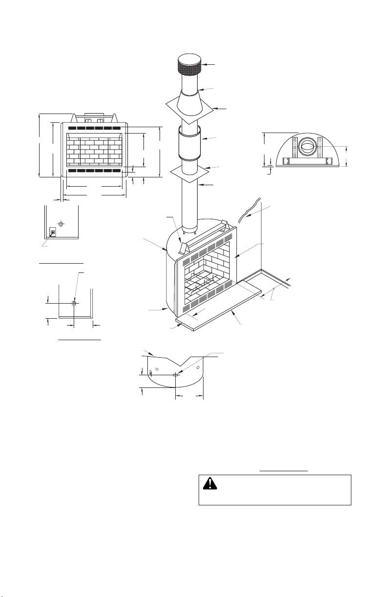
SPECIFICATIONS
42"
36
1
/4"
33
1
/4"
22
1
/8"
6
3
/4"
7
3
/4"
9
3
/8"
3"
36"
41"
1"
J-Box
Access
RH SIDE VIEW
LH SIDE VIEW
Gas Line Conduit
Sleeve (Both Sides)
1/2" Air Space
Back and Sides
0" To T o p
Spacer
Round Top Termination
Storm Collar
Flashing
Firestop
1" Airspace
To Combustible
Materials
Combustible
Wall Board
No Combustible
Material On Face
Not Less Than 14"
To Perpendicular
Sidewall
Hearth Extension
52" x 16"
0" To
Bottom
8" Each
Side
22
1
/16"
5/8"
13"
Rear View
of Fireplace
Opening for
Outside Air
(Left or Right
Side Application)
Firestop
Thimble
9
1
/2"
27"
SELECTING LOCATION
FIREPLACE INSTALLATION
To determine the safest and most efcient
location for the replace, you must take into
consideration the following guidelines:
1. The location must allow for proper clearances (see Figures 1 and 2, page 4).
2. Consider a location where the heat output
will not be affected by drafts, air conditioning ducts, windows or doors.
110746-01P 3
3. A location that av oids the cutting of
joists or roof rafters will make installation
easier.
4. An outside air kit is available with this
replace (see Outside Air Kit on page 6).
WARNING: Do not install this
appliance in a bedroom.
www.desatech.com
13" Min.
Maintain 1/2" Air Space
Between Framing
and Fireplace
43
5
/8"
Min.
41 3/4" Min.
61
11/16" Min.
FIREPLACE INSTALLATION
Effective Height of
Te rmination Cap
Effective Height of
Termination Cap
Effective Height of
Te rmination Cap
RT-8DM
RT-8DM
RT-8DM
14' Min.
Height
2' Max
Pipe Length
30E-8DM
11 ' for
Manufactured
Home
Application
14' Min.
Height
11 ' for
Manufactured
Home
Application
40' Max.
Height
20' for
Manufactured
Home
Application
Effective Height of
Te rmination Cap
RT-8DM
30E-8DM
40' Max.
Height
20' for
Manufactured
Home
Application
42 1/4"
41
3
/4"
22
5
/8"
10"
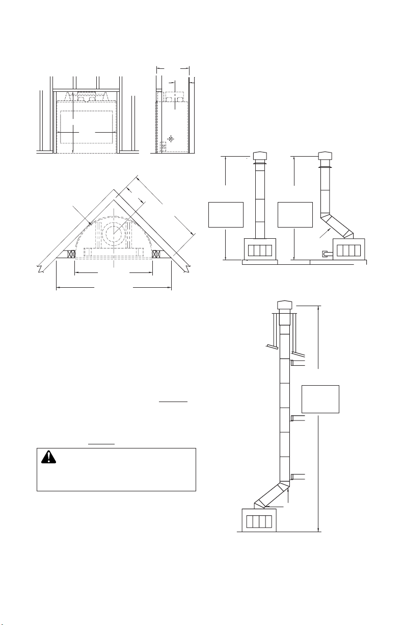
Figure 1 - Framing Dimensions
Continued
Maximum height of any system is 40 feet.*
This measurement includes replace, chimney sections and height of termination assembly at level of ue gas outlet (see Figure 3).
*For manufactured home application, minimum
height is 11' for straight ue or ue with one elbow
set. Maximum height of any system is 20'.
MINIMUM CLEARANCE TO
COMBUSTIBLES
Back and sides of replace 1/2" minimum*
Floor** 0" minimum
Wall to front of replace 36" minimum
Perpendicular wall to opening 14" minimum
Top spacers 0" minimum
Mantel clearances see Mantels,
page 15
Chimney outer pipe surfaces 1" minimum
* Not required at nailing anges
** See step 2 of Framing, page 5
quired air spaces with insulation
or other materials.
Minimum/Maximum Chimney Height
Minimum height ofthe chimney, measured
from base of replace to ue gas outlet of
termination, is 14 feet* for straight ue or a
ue with one elbow set. Maximum distance
between elbows is 2 feet.
Figure 2 - Corner Installation
WARNING: Do not pack re-
www.desatech.com
Standard
Installation
Figure 3 - Standard and Alternate
Venting Installation
Alternate
Installation
Alternate
Installation
110746-01P4
FIREPLACE INSTALLATION
Continued
FRAMING
1. Frame opening for replace using dimensions shown in Figures 1 and 2.
2. If replace is to be installed directly on
carpeting, tile (other than ceramic) or any
combustible material other than wood
ooring, replace must be installed on a
metal or wood panel extending full width
and depth of replace. (It is acceptable to
cover two outside ends or columns of top
louver panel leaving four center columns
open).
3. Set replace directly in front of this opening and slide unit back until nailing anges
touch side framing.
4. Check level of replace and shim with
sheet metal if necessary.
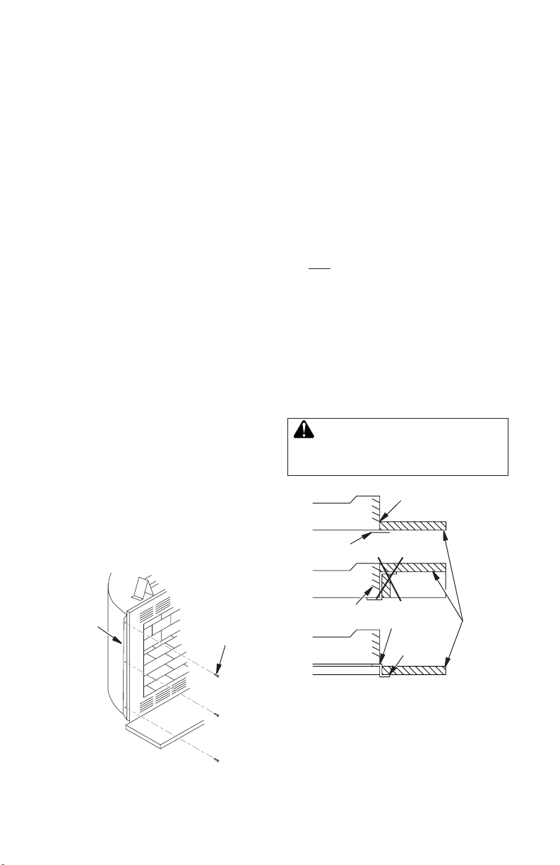
5. Before securing replace to prepared framing, metal ember protector (provided) must
be placed between hearth extension (not
supplied) and under bottom front edge of
replace to protect against glowing embers
falling through. If replace is to be installed
on a raised platform, a Z-type ember protector (not supplied) must be fabricated to
t your required platform height. Ember
protector should extend under replace
a minimum of 1
should be made of metal material.
6. Using screws or nails, secure replace to
framing through anges located on sides
of replace (see Figure 4).
1
/2". The ember protector
HEARTH EXTENSION
A hearth extension projecting a minimum of
16" in front of and a minimum of 8" beyond
each side of the replace opening is required
to protect combustible oor construction in
front of the replace. Use an equal material
which meets the following specications: a
layer of noncombustible, inorganic material
having a thermal conductivity of K=0.84 BTU
IN/FT, HR. F (or less) at 1" thick. For example,
if the material selected has a K factor of 0.25,
such as glass ber, the following formula
would apply:
0.25 x 1.0" = 0.30" thickness required
0.84
Thermal conductivity "K" of materials can be
obtained from the manufacturer or supplier of
the noncombustible material. If the hearth extension is to be covered, use noncombustible
material such as tile, slate, brick, concrete,
metal, glass, marble, stone, etc. Provide
a means to prevent hearth extension from
shifting and seal gap between replace frame
and hearth extension with a noncombustible
material (see Figure 5).
WARNING: Hearth extension
is to be installed only as shown
in Figure 5.
Fireplace
Front
Ember
Protector
Seal Gap
Raised
Hearth
Nailing
Flange
Figure 4 - Nailing Flanges
110746-01P 5
Screw
or Nail
www.desatech.com
DO NOT Block Louvers
Fireplace Front
Elevated
Figure 5 - Hearth Extension
NO
Seal Gap
Ember
Protector
Hearth
Extension
OF FIREPLACE
OUTER WRAPPER
TO
POWER SOURCE
ELECTRICAL
COVER PLATE
AND STRAIN RELIEF
POWER SOURCE
WIRING (NOT SUPPLIED)
FIREPLACE
(NOT SUPPLIED)
WIRE NUT (3x)
HOUSING
PRE-WIRED
RECEPTACLE
AND GROUND
CHASSIS
GROUND
FIREPLACE INSTALLATION
Continued
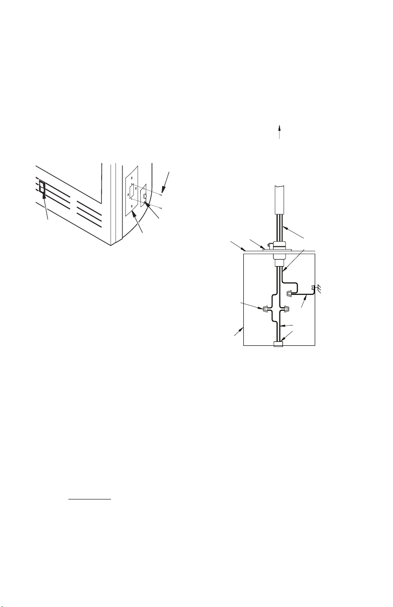
FAN KIT ASSEMBLY (BK2)
A fan kit assembly is preinstalled in this
replace. Use of blowers or fans other than
model BK2 voids warranty. Fan is operated by
pressing rocker switch located at lower right
hand corner of replace face. Fan kit electrical connections are made through electrical
cover plate located on side of replace as
shown in Figure 6.
Screws
5. Secure electrical cover plate with screws
previously removed.
6. Tighten strain relief plastic screw
Note: Electrical housing and cover plate have
sharp edges. Wear protective gloves.
Rocker
Switch
Figure 6 - Fan Kit BK2 Electrical Cover
Fan Kit Wiring Instructions
1. Loosen strain relief by turning plastic screw
2. Remove electrical cover plate (with strain
3. Slide power source wiring through strain
4. Place all wiring connections into electric
OUTSIDE AIR KIT
Installation of an outside air kit should be
complet ed during the roug h fra mi ng of
replace due to nature of its location. The
supplied ex duct measures approximately
10" compressed and up to approximately 36"
extended. Outside combustion air is accessed
through mobile home oor using air kit model
AK6E or a side wall using air kit model AK6WE (see Accessories on page 18).
Installer may choose either left or right side
mounting to allow for proper wall/rafte r
clearances.
Strain
Relief
Electrical
Cover Plate
counterclockwise.
relief) from replace by removing two sheet
metal screws .
relief opening and electrical cover plate
and make all necessary connections
housing as shown in Figure 7.
VENTING INSTALLATION
Figure 7 - Fan Kit Wiring Diagram
A combustion air chute may be installed to
back of replace facing left or installed on a
at wall, or may be rotated 90° facing right
for a corner application. Installer may choose
either installation method to allow for proper
wall/rafter clearances.
For AK6-WE Only: Construct a 4.5" x 4.5"
framing or opening on exterior wall (see
Figure 8, page 7).
For AK6E Only: The outside air vent is installed through a ventilated crawl space (see
Figure 9, page 7).
www.desatech.com
110746-01P6
 Loading...