

Vexar 368STM-1 Owners & Installation Manual
36" SEE THROUGH SMOOTH FACE
P F S
®
USC
WOOD BURNING FIREPLACE
OWNER’S INSTALLATION MANUAL
368STM with Brushed
Brass Finish Doors
368STM-1 with
Platinum Finish Doors
Includes Combustion Air Kit
and Bi-Fold Doors
SAVE THIS BOOK
This book is valuable. In addition to instructing you
on how to install and maintain your appliance, it also
contains information that will enable you to obtain replacement parts or accessory items when needed. Keep
it with your other important papers.
This replace is approved for use as a wood burning
replace or for use with a vented gas log approved to
ANS Z21.60 or Z21.84 standards or for use with a ventfree gas log heater approved to ANS Z21.11.2 standard.
A vent-free log can only be installed in an aftermarket
(completion of sale, not for purpose of resale from the
manufacturer), permanently located, manufactured
(mobile) home, where not prohibited by local codes. A
hood must be installed when using a vent-free gas log
heater (see Accessories, page 14).
This rebox meets the construction and safety standards of H.U.D. for application in mobile homes when
installed according to these instructions.
INSTALLER: Leave this manual with the appliance.
CONSUMER: Retain this manual for future reference.
For more information, visit www.fmiproducts.com
Safety .................................................................. 2
TABLE OF CONTENTS
Specications ...................................................... 3
Fireplace Installation............................................ 3
Venting Installation .............................................. 6
Optional Gas Line Installation............................ 12
SAFETY
Operation and Maintenance .............................. 13
Accessories ....................................................... 14
Replacement Parts ............................................ 16
Technical Service............................................... 16
WARNING: Improper installation, adjustment, alteration, service or maintenance
can cause injury, property
damage or loss of life. Refer
to this manual for assistance
or additional information.
Consult a qualied installer
or local distributor.
IMPORTANT: Check HUD requirements before installing this
replace.
Model 368STM is specically designed for use
in manufactured mobile homes. This replace
includes a manual control fan system, combustion air kit and bi-fold doors.
Before beginning installation of replace, read
these instructions through completely.
• This Style Crest, Inc. replace and its components are safe when installed according
to this installation manual. Unless you use
Style Crest, Inc. components, which have
been designed and tested for replace
system, you may cause a re hazard.
• The Style Crest, Inc. warranty will be voided
by and Style Crest, Inc. disclaims any responsibility for the following actions.
a. Modication of replace, components,
doors, blower, fans, air inlet system and
damper control.
b. Use of any component part not manu-
factured or approved by Style Crest,
Inc. in combination with a Style Crest,
Inc. replace system.
Proper installation is the most important step
in ensuring safe and continuous operation
of replace. Consult local building codes as
to the particular requirements concerned
with installation of all factory built replaces.
Although grounding may not be required by
code, the manufacturer recommends it.
www.fmiproducts.com
CAUTION: The structural integ-
rity of the mobile home oor and
ceiling/roof must be maintained.
WARNING: Do not install a
replace insert in this box unless
the manufacturer's instructions
with the insert specically state
this replace has been tested for
use with the insert.
FOR YOUR SAFETY
• Do not store or use gasoline
or any other ammable vapors
or liquids in the vicinity of this
or any other appliance.
• Due to high temperatures, the
appliance should be located
out of trafc and away from
furniture and draperies.
• Do not place clothing or other
ammable materials on or near
the appliance.
• Never leave children unattended when a re is burning
in the replace.
This replace is not intended to
be used as a substitute for a furnace to heat an entire home. Use
for supplemental heat only.
This wood burning replace complies with the UL 127 standard as
a FACTORY BUILT FIREPLACE.
This replace meets construction and safety standards of
HUD for application in mobile
homes when installed according
to these directions.
56149J2
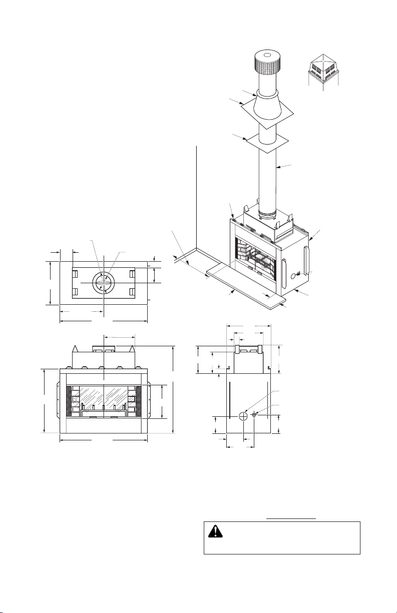
SPECIFICATIONS
24"
37 1/2"
20 1/2"
10
1
/4"
53 1/2"
17
1
/2"
4
1
/2"
6"
12
3
/8" O.D.
18" I.D.
21 5/16"
15 1/2"
42
5
/8"
36 1/2"
9 1/2"
2
1
/2"
Gas Line
Conduit
Outside Air
(Left Side
Shown)
Storm Collar
Flashing
Firestop
0" To Top
Spacer
0" To
Bottom
1" Air Space
Back and
Sides
2" Airspace to
Combustible
Materials
12" Minimum
to Perpendicular
Sidewall
Outside Air
Intake (Located
on Both Sides
of Fireplace)
8" Each Side
Hearth
Extension
52" x 16"
Round To p
Te rmination
Square Chase
Te rmination
11/2"
11 1/4"
12"
18"
12"
7"
24"
19"
Left Side View
To p View
Front View
SELECTING LOCATION
FIREPLACE INSTALLATION
To determine the safest and most efcient
location for the replace, you must take into
consideration the following guidelines:
1.
The location must allow for proper clearances (see Figure 1 and Figure 2, page 4).
2. Consider a location where the heat output
will not be affected by drafts, air condition-
3. A location that avoids cutting of joists or
roof rafters will make installation easier.
4. An outside air kit is available with this
replace (see Outside Air Kit on page 5).
WARNING: Do not install this
appliance in a bedroom.
ing ducts, windows or doors.
56149J 3
www.fmiproducts.com
FIREPLACE INSTALLATION
As Required by Design as Long
as Ceiling Clearance Is Maintained
53
7
/
8
"
(136 cm) Min.
44
5
/
8
"
(113 cm)
Min.
Platform Must be
Solid, Flat and
Fully Supported
22
3
/
4
"
(58 cm)
"Z" Type
Ember Protector
(Not Supplied)
12 3/8" Dia.
(31.4 cm) Outer Pipe
2" (5.1 cm) Min.
Clearance From Outer
Pipes to Combustibles
1" (2.5 cm) Min.
T o Combustibles
21
5
/16"
(54 cm)
42 5/8"
(108 cm)
24"
(61 cm)
12"
(31 cm)
MINIMUM CLEARANCE TO
COMBUSTIBLES
Back and sides of replace 1" minimum*
Floor** 0" minimum
Wall to front of replace 36" minimum
Perpendicular wall to opening 14" minimum
Top spacers 0" minimum
Mantel clearances see Mantels, page 14
Chimney outer pipe surfaces 1" minimum
* Not required at nailing anges
** See step 2 of Installing Fireplace
WARNING: Do not pack required air spaces with insulation
or other materials.
Minimum/Maximum Chimney Height
Minimum height of chimney, measured from
base of replace to ue gas outlet of termination, is 15 feet for straight ue and 16 feet for
a ue with one elbow set. Maximum distance
between elbows is 2 feet. For systems with
2 elbow sets, minimum height is 25 feet.
Maximum height of any system is 40 feet. This
measurement includes replace, chimney
sections and height of termination assembly
at level of ue gas outlet (see Figure 15,
page 10).
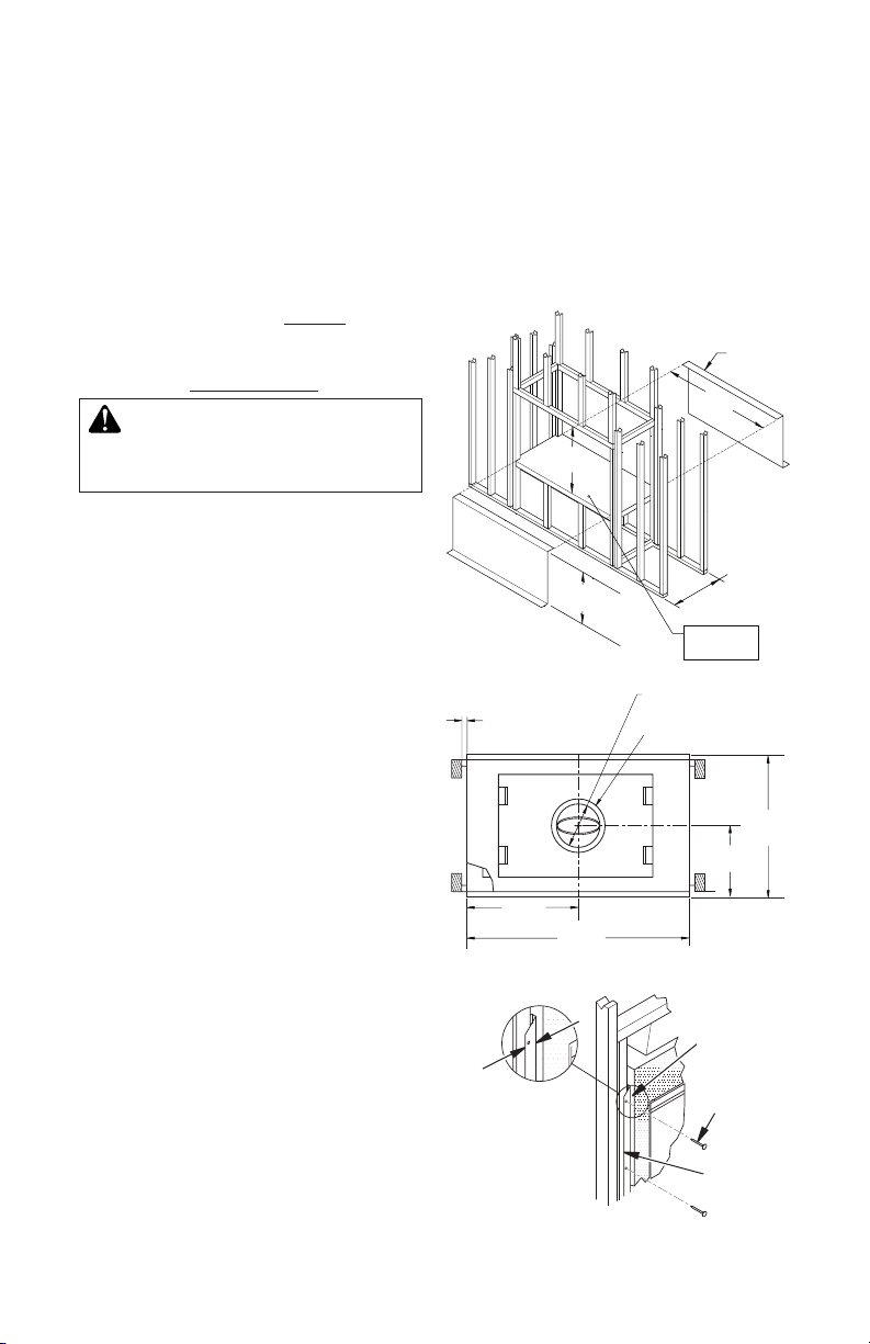
FRAMING
1. Frame opening for replace using dimensions shown in Figure 1.
2. If replace is to be installed directly on
carpeting, tile (other than ceramic) or any
combustible material other than wood
ooring, the replace must be installed
upon a metal or wood panel extending
the full width and depth of replace.
3. Set replace directly in front of opening
and slide unit back until nailing anges
touch side framing.
4. Check level of replace and shim with
sheet metal if necessary.
5. Before securing fireplace to prepared
framing, provided ember protector must
be placed between hearth extension (not
supplied) and under bottom front edge of
replace to protect against glowing embers
falling through. If replace is to be installed
on a raised platform, a Z-type ember protector (not supplied) must be fabricated to
Continued
t your required platform height. Ember
protector should extend under replace a
minimum of 1 1/2". Ember protector should
be made of sheet metal (28 gauge minimum to prevent corrosion.
6. Using screws or nails, secure replace to
framing through anges located on sides
of replace (see Figure 2).
Figure 1 - Framing Dimensions
3/4"
Clearance is
Not Required
at Nailing
Flanges
Figure 2 - Nailing Flanges
www.fmiproducts.com
Nailing
Flanges
Nails or
Screws
Prepared
Framing
56149J4
FIREPLACE INSTALLATION
FIREBOX
SAFE ZONE
Continued
HEARTH EXTENSION
A hearth extension projecting a minimum of
16" in front of and a minimum of 8" beyond
each side of replace opening is required
to protect combustible oor construction in
front of replace. Use Style Crest, Inc. hearth
extension (see Accessories, page 14) HE-36
or an equal material which meets the following specications: a layer of noncombustible,
inorganic material having a thermal conductivity of K=0.84 BTU IN/FT, HR. F (or less) at 1"
thick. For example, if material selected has
a K factor of 0.25, such as glass ber, the
following formula would apply:
0.25 x 1.0" = 0.30" thickness required
0.84
Thermal conductivity "K" of materials can be
obtained from the manufacturer or supplier of
the noncombustible material. If hearth extension is to be covered, use noncombustible
material such as tile, slate, brick, concrete,
metal, glass, marble, stone, etc. Provide
a means to prevent hearth extension from
shifting and seal gap between replace frame
and hearth extension with a noncombustible
material (see Figure 3).
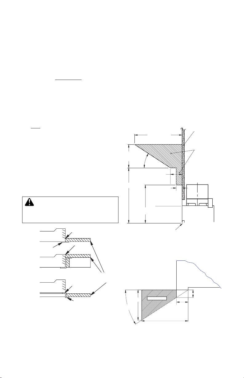
MANTELS
A mantel may be installed if desired (see
Figure 4). Woodwork such as wood trims,
mantels or any other combustible material
projecting from the front face must not be
placed within 9" of replace opening. Combustible materials above 9" and projecting more
than 1 1/2" from replace must not be placed
less than 12" from top opening of replace
(NFPA STD 211, Sec. 7-3.3.3).
Mantels or any other combustible material
also may come up to side edge of black metal
face of replace only if projection from front
face falls within limits shown in Figure 5.
Combustible
Material
Safe
Zone for
Projection of
Combustible
Materials
6"
Ref.
12" Min.
12 1/4" Ref.
33°
3" Nom.
11/2" Max.
WARNING: Hearth extension
is to be installed only as shown
9" Min.
in Figure 3.
Fireplace
Front
Ember
Protector
Fireplace Front
Raised Hearth
Fireplace Front
Elevated
Figure 3 - Hearth Extension
56149J 5
Seal Gap
Seal
Gap
Seal Gap
Ember Protector
Hearth
Extension
7.75"
33°
Figure 5 - Projection Limits to Front Face
www.fmiproducts.com
Fireplace
Opening
Figure 4 - Mantel Clearances to
Combustible Material
Top View of
Fireplace
Minimum 12" from
Perpendicular Side
Wall
Upper
Section of
Fireplace
2" Max.
3"
Combustible
Material Must
Not Overlap
Front Face
 Loading...