

Vetus DIESEL VH4.65, VH4.80 Operation Manual

VH4.65
VH4.80
Operation manual
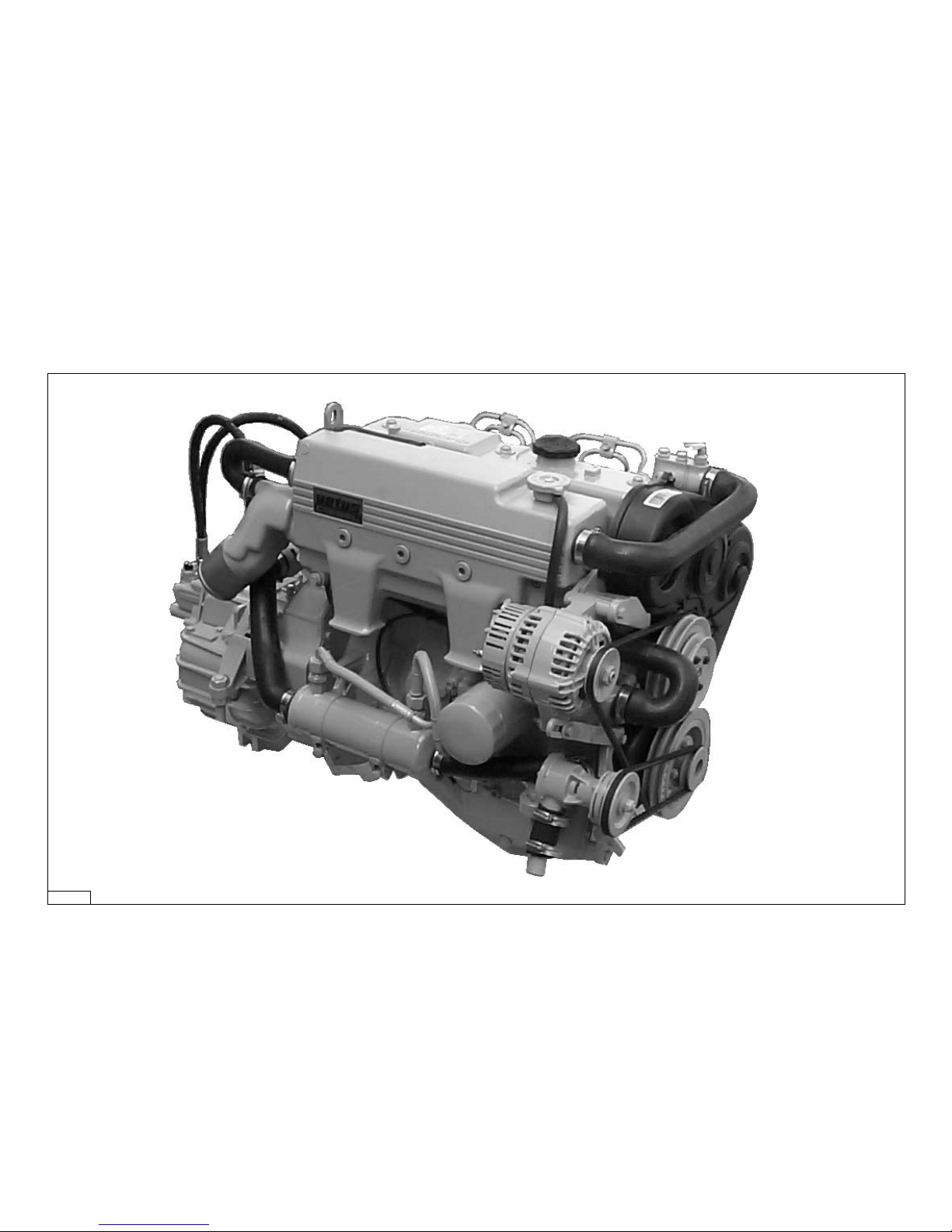
VD01079
VH4.80
1
Operation manual
Please enter the serial numbers here.
These numbers should be quoted when inquiring about Customer
Service, Repairs or Spare Parts (see page 6).
We reserve the right to make any changes without previous
notice.
Serial numbers
Engine serial number Vetus:
Hyundai:
Gearbox serial number:
VH4.65
VH4.80
350102.01 (STM4994)

Please read and observe the information given in this operation
manual. This will enable you to avoid accidents, preserve the
manufacturer’s warranty and maintain the engine in peak operating condition.
For the Guarantee Conditions, see the Vetus Diesel Service and
Warrantee Manual.
This engine has been built exclusively for the application specified in the scope of supply and is to be used only for the intended purpose. Any use exceeding that scope is considered to be
contrary to the intended purpose. The manufacturer will not not
assume responsibility for any damage resulting therefrom. The
risks involved are to be borne by the user.
Use in accordance with the intended purpose also implies compliance with the conditions laid down by the manufacturer for
operation, maintenance and servicing. The engine should only
be operated, maintained and serviced by persons which are
familiar with the former and the hazards involved.
The relevant accident prevention guidelines and other generally accepted safety and industrial hygiene regulations must be
observed.
Unauthorized engine modifications will invalidate any liability
claims against the manufacturer for resultant damage.
Manipulations of the injection and regulating system may also
influence the performance of the engine, and its emissions.
Adherence to legislation on pollution cannot be guaranteed
under such conditions.
2

Serial numbers 1
1 Introduction 4
2 Engine description
General 6
Identification of engine parts 8
Control panels 10
3 Use
General guidelines 12
First commissioning 13
Running-in 16
Starting 17
(Pre-heating) 18
Cruising 20
Stopping 22
4 Routine maintenance
Introduction 23
Maintenance schedule 24
5 Maintenance
Checking the oil level 25
Checking the coolant level 26
Checking and cleaning the
raw water strainer 27
Draining water from the water
separator/fuel filter 28
(Bleeding) 29
Battery, cables and cable
connections 30
Changing the oil 32
Checking the gearbox oil level 34
Changing the gearbox oil 35
Replacing the fuel filter 36
Cleaning fuel lift pump 37
Checking the V-belts 38
Checking flexible engine mounts 40
Checking hose connections 40
Checking fastenings 40
Checking valve clearance 41
Checking the raw water pump 44
Coolant replacement 46
Cleaning the heat exchanger 48
Checking engine rpm 51
6 Winter lay-up
Winter storage procedure 52
Recommissioning after winter
storage 55
7 Troubleshooting 58
8 Technical Data 64
9 Operating media
Lubrication Oil 66
Fuel 67
Coolant 68
10 Wiring Diagrams 69
11 Overall Dimensions 72
3
Contents

4
Dear Customer,
Vetus diesel engines are designed both for pleasure and commercial craft. Consequently, a wide range of variants are offered
to meet the requirements of specific cases.
Your engine is appropriately equipped for your vessel, which
means that not necessarily all components described in this
manual are mounted to your engine.
We have endeavoured to highlight any differences so that you
will able to locate the operating and maintenance instructions
relevant to your engine quickly and easily.
Please read this manual before starting your engine and always
observe the operating and maintenance instructions.
We are available to help with any additional inquiries.
Sincerely, VETUS N.V.
Introduction

5
Safety measures
Introduction
All safety instructions in this manual are designated by the accompanying symbol. Please
follow them carefully.
Pass the safety instructions to other persons operating the
engine as well.
General regulations and laws for safety and accident prevention
must also be observed.
• Never attempt to touch moving parts when the engine is running.
• Never touch hot parts of the engine, and keep flammable
materials well away from the engine.
• Always stop the engine before checking or adjusting components.
• Always stop the engine before checking or topping up the
coolant or oil.
• Never open cap on top of header tank when the engine is at
operating temperature.
• Always carry out maintenance safely by only using tools well
matched in size.

6
Engine data tag
The vetus engine serial number and performance data are printed on the engine
data tag.
Model and engine serial number must be
given when ordering spare parts.
Engine data tag location
The vetus engine data tag is attached to
the valve cover.
Engine serial number
The HyuNdai engine serial number is
stamped at the indicated spot.
Engine description
General
VH480---A
D4BB1207830
A
4000 59 80
200001
ø88 MM
VD00232 VD01080 VD01081
7
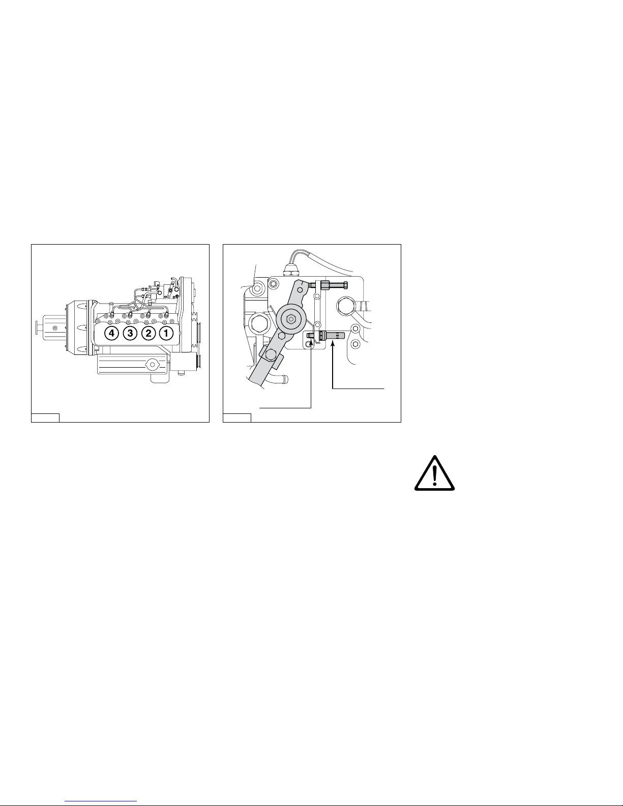
Cylinder numbering
Cylinders are numbered consecutively,
beginning at the front end.
Fuel pump seal
The manufacturer shall not be held liable
for damages resulting from adjustments
made to the fuel injection pump.
The maximum engine speed adjustment
screw has been sealed to prevent this.
Adjustments to the fuel
pump are to be carried out
by authorized Vetus-Service
specialists only.
General
Engine description
VD00230
Lead seal
Maximum rpm
adjustment screw
VD00229
Port-side
Starboard
8
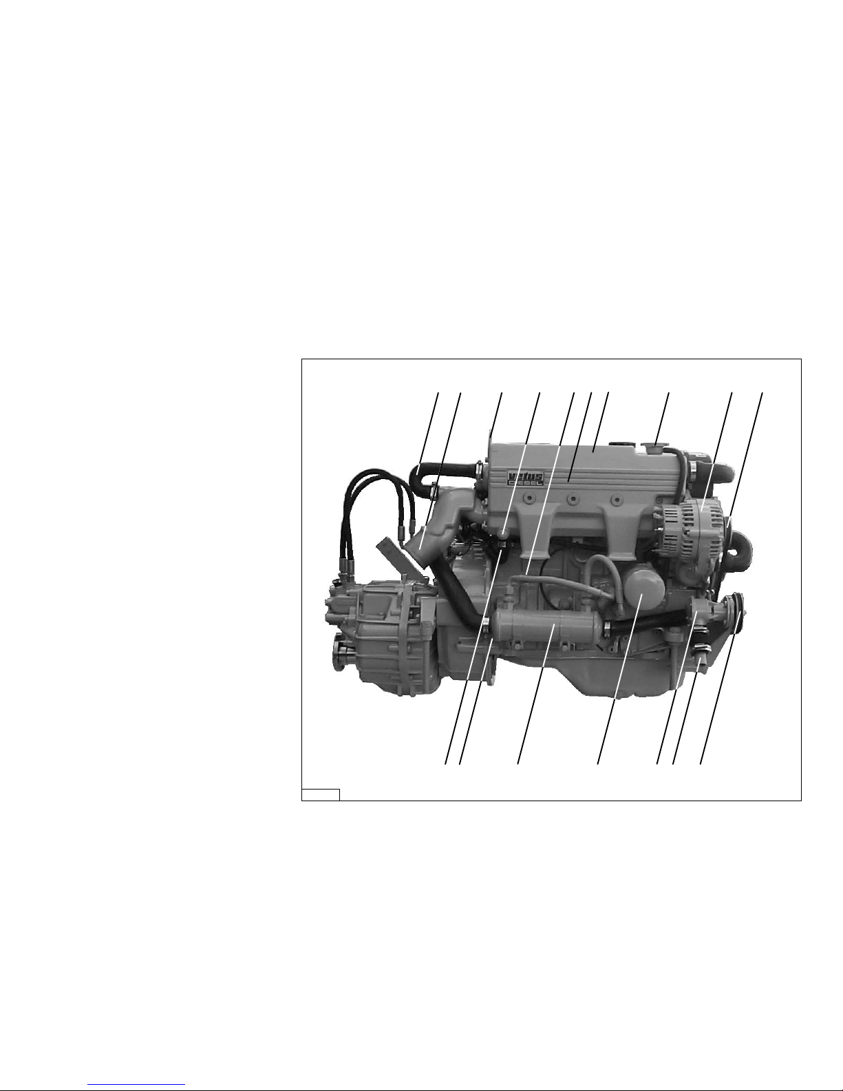
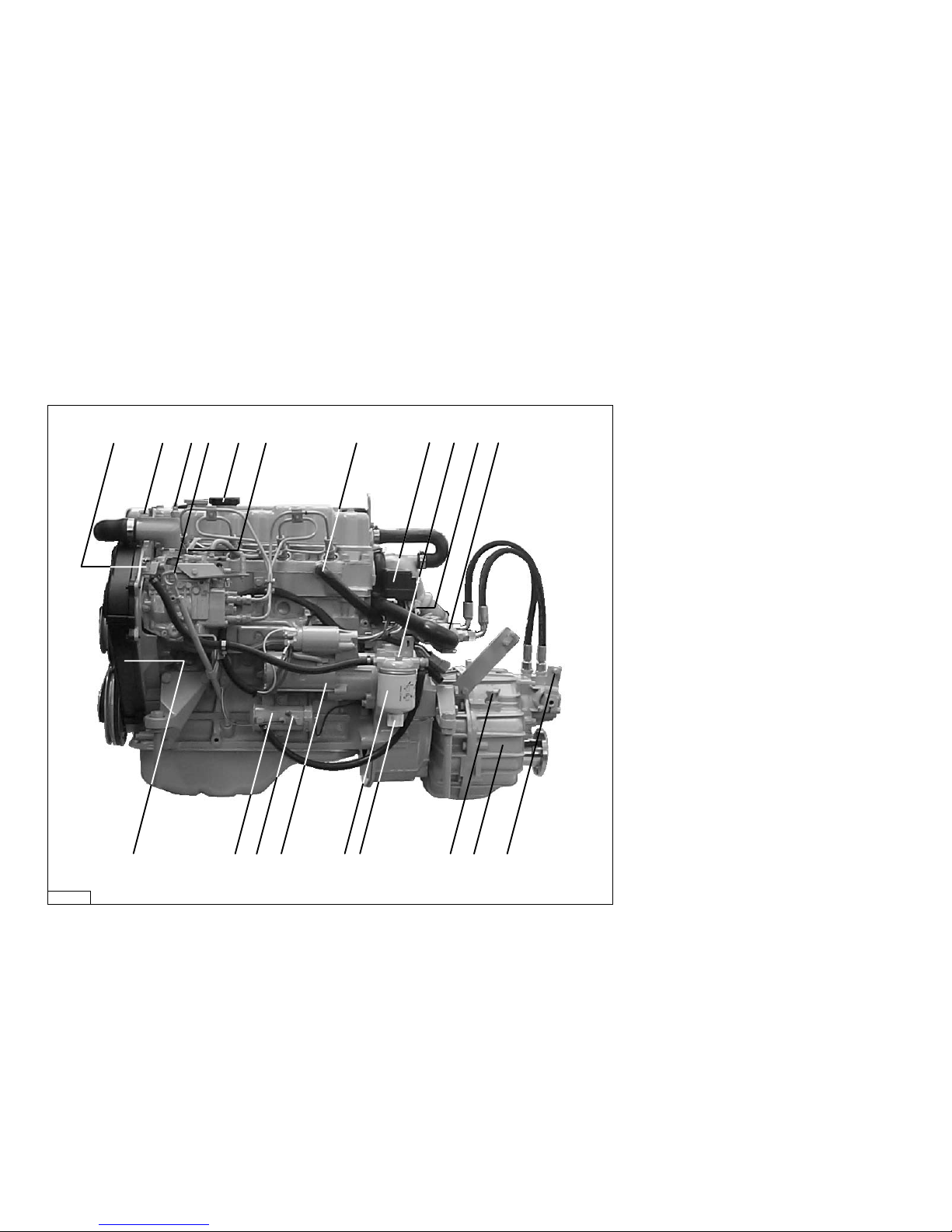
1 Airvent connection
2 Exhaust injection bend
VH4.65: ø 60 mm
VH4.80: ø 75 mm
3 Lifting eye
4, 5 Cooling system drain plug
6 Heat exchanger
7 Expansion tank
8 Filler cap for cooling system
9 Alternator
10 V-belt alternator/ coolant pump
11 V-belt raw water pump
12 Raw water inlet ø 25 mm
13 Raw water pump
14 Oil filter
15 Oil cooler
16 Raw water drain plug
17 Calorifier connection, engine ‘IN’
(ø 22 mm)
18 Connection for throttle push-pull
cable
19 Cooling system air bleed nipple
20 Temp. switch coolant
Engine description
Identification of engine parts
Starboard
1 2 3 4 5 6 7 8 9 10
11121314151617
VD01105
VH4.80
9
21 Oil dipstick
22 Oil filler cap
23 Fuel return pipe connection
ø 8 mm
24 Calorifier connection, engine ‘OUT’
(ø 17 mm)
25 Electrical system connection box
26 Water separator/fuel filter air bleed
nipple
27 Fuse
28 Gearbox lube oil cooler
29 Connection for gearbox push-pull
cable
30 Gearbox
31 Gearbox filler cap/ oil dipstick
32 Water separator/ fuel filter drain
plug
33 Water separator/ fuel filter
34 Starter motor
35 Fuel supply pipe connection
ø 8 mm
36 Fuel lift pump
37 Distribution cover
Identification of engine parts
Port-side
Engine description
19 20 21 22 23 24 26 27 28
293031323334353637
18 25
VD01106
VH4.80

10
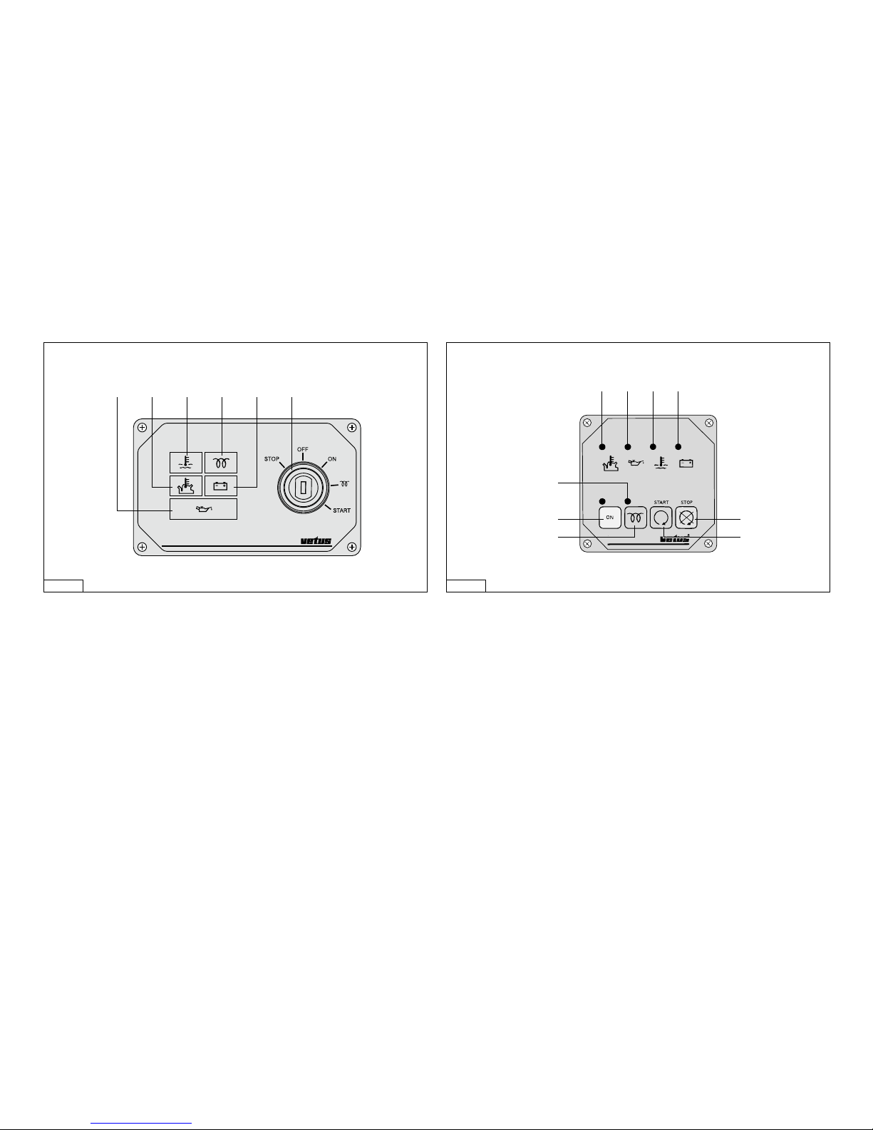
Basic panel (model 22)
Fly-bridge panel (excl. voltmeter, model 21)
Extended panel (model 34)
Engine description
Control panels
5
3
7
8
6
4
9
1 2
VD00103
5
3
7
8
6
4
9
1 210
11
VD00104
11
Sailingboat panel (model 10) Push button panel (model 00)
Control panels
Engine description
1 Tachometer/Operating hours counter
2 Voltmeter
3 Starter pre-heat switch/lock
4 Warning light high raw water temperature
5 Warning light low oil pressure
6 Warning light high coolant temperature
7 Warning light battery charging
8 Indicator light pre-heating
9 Warning light gearbox low oil pressure *
10 Temperature gauge, coolant
11 Oil pressure gauge
12 On push button switch
13 Pre-heating push button switch
14 Starter push button switch
15 Stop push button switch
*) This is an option, not fitted as standard.
5
3
7
8
6
4
VD00102 VD00101
4 5 6 7
8
12
13
15
14

12
General guidelines for use
Implementing the following recommendations will result in longer
life and better performance and more economical operation of
your engine.
• Carry out the maintenance described regularly, including the
‘Daily procedures before starting’.
• Use anti-freeze in the engine coolant all year long, this helps
prevent corrosion as well as protecting against frost damage.
For specifications see page 68.
• Never run the engine without a thermostat.
• Use a good quality lubricating oil. For specifications see page
66.
• Use a good quality diesel fuel that is free of water and other
pollutants.
• Always stop the engine immediately if one of the warning
lamps for oil pressure, high coolant temperature, high raw
water temperature or battery charging lights up.
Use
General guidelines
13
Commissioning the engine
Before starting the engine for the first time,
the following procedures must be carried
out:
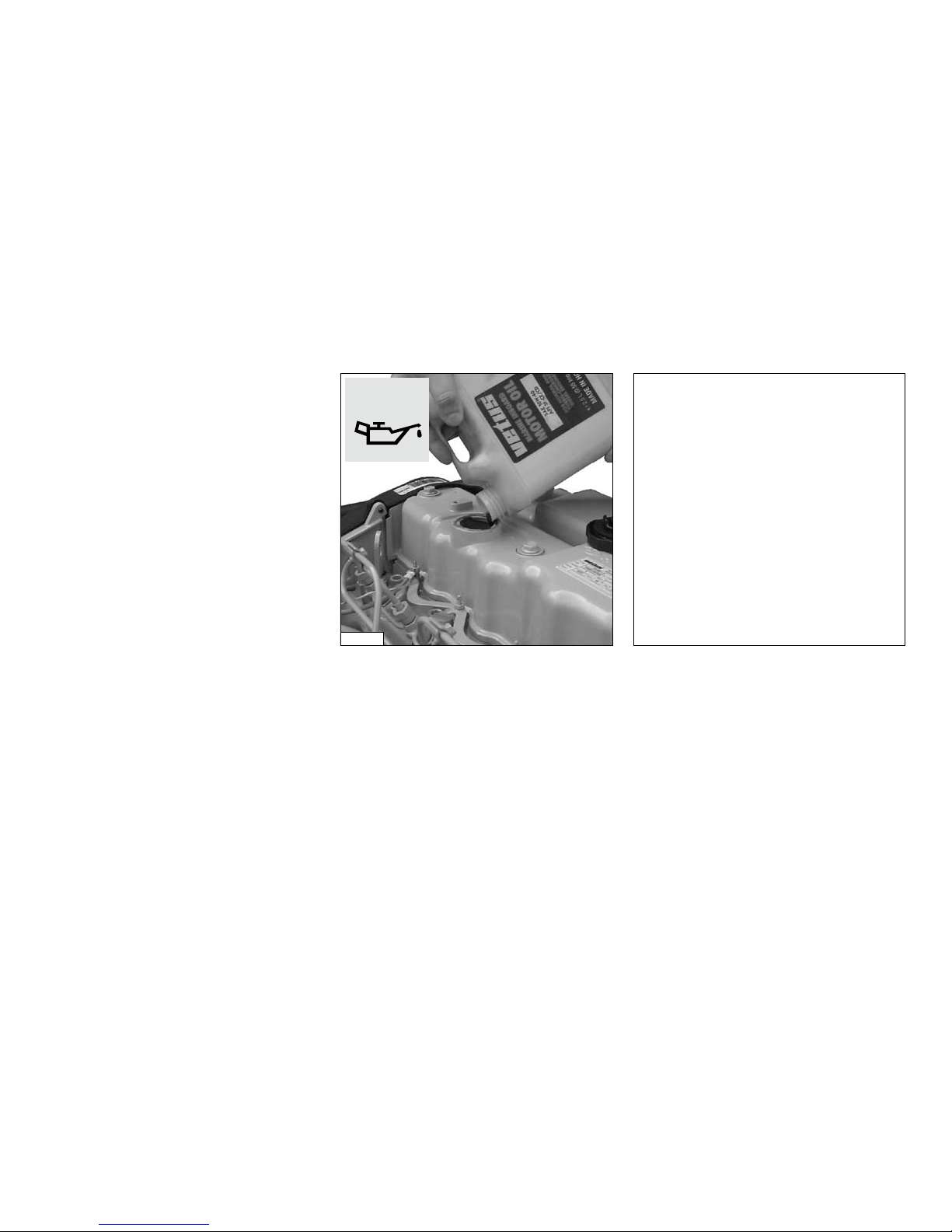
Filling with engine oil
As a rule engines are delivered empty of
oil.
Fill the engine with oil through the filler
neck on top of the valve cover, for quantity
and specification see page 66.
Check the oil level with the dipstick, see
page 25.
First commissioning
Use
Engine Oil
4.9 litres (1.1 UKgal) 15W40
API: CD, CE or CF4
CCMC: D4, D5
For example:
- Vetus Marine Inboard Diesel Motor
Oil
- Shell Super Diesel T
OIL
VD01082

Filling gearbox with oil
Fill the gearbox with oil.
Check the oil level with the dipstick, see
page 34.
ZF Hurth:
model HBW250 : 0,75 litres ATF*)
(ZF25M) (1.3 UKpt)
model HBW250A : 0,8 litres ATF*)
(ZF25MA) (1.4 UKpt)
model HSW250A : 1,8 litres ATF*)
(ZF25A) (3.2 UKpt)
model HSW250H : 2,5 litres ATF*)
(ZF25) (4.4 UKpt)
*) ATF: Automatic Transmission Fluid
type A, Suffix A.
Technodrive:
model TMC260 : 1,2 litres ATF*)
(2.1 UKpt)
model TM345H : 1,6 litres Engine oil
(2.8 UKpt) SAE 20W40-CD
model TM345A : 1,6 litres Engine oil
(2.8 UKpt) SAE 20W40-CD
*) ATF: Automatic Transmission Fluid
type A, Suffix A.
First commissioning
Use
14
OIL
VD01100
Vetus engines are normally equipped
with ZF-Hurth or Technodrive gearboxes.
In case your engine is equipped with
another brand of gearbox follow the
instructions given in the supplied owners manual.
15
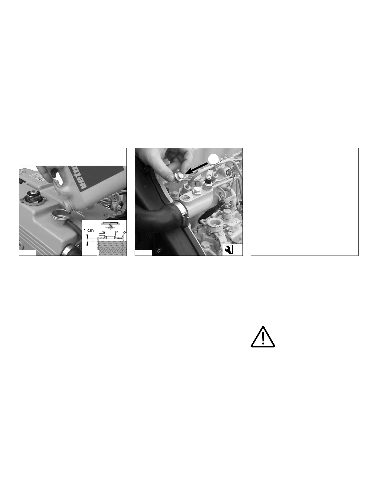
Filling the cooling system
Remove the cap of the filler neck on the
top of the heat exchanger housing.
Remove plug A, so that air can escape
from the cooling system.
Fill the cooling system. Replace plug A as
soon as coolant flows out.
Use a mixture of 40% antifreeze (ethyleneglycol based) and 60% tap water or use a
special coolant.
For specifications see page 68.
The level of the coolant must be approx.
1 cm (3/8”) below the lower edge of the
filler neck.
Bleeding will take place automatically during filling!
Replace the filler cap.
After the engine has run for the first time
and has reached operating temperature
and has cooled down again to ambient
temperature, check the coolant level in the
heat exchanger housing.
If necessary, add coolant.
Use
First commissioning
Water Heater
If a water heater is connected to the
engine and this heater is positioned
above the upper side of the engine
then bleeding of the heater will not
take place automatically! Fill the heater
separately to bleed the cooling system
completely.
Never fill the cooling system
with sea water or brackish
water.
A
13
VD01083 VD00144
(3/8”)
VD01084
Coolant
quantity :
7.1 litres (1.6 UKgal)
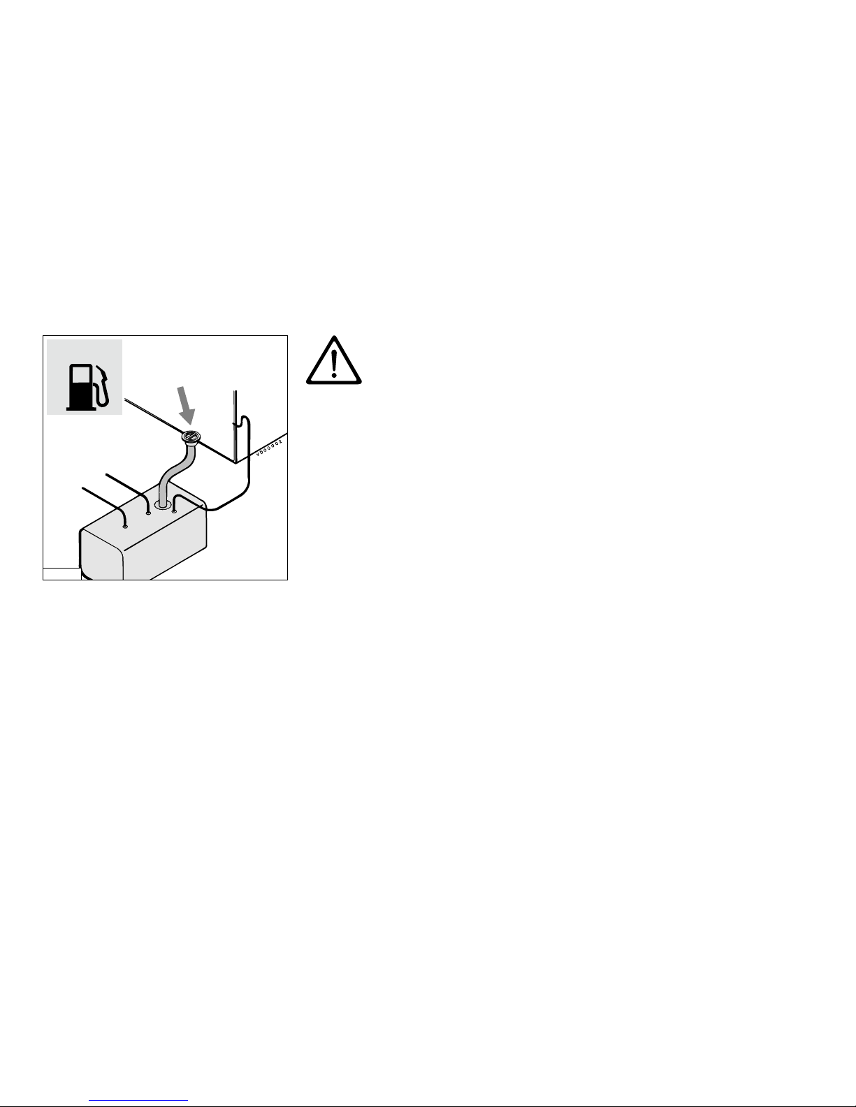
Fuel
Ensure that the fuel tank is filled with
diesel fuel.
Use only clean, water-free, commercial
approved diesel fuel.
For fuel grade see page 67.
Bleed the fuel system, see page 29.
Other preparations
• Check battery and cable connections.
• Start the engine, see page 17, and let it
run for about 10 minutes without load.
Check the engine and all connections
(fuel, cooling water and exhaust) for
leaks.
Running-in
In order to ensure a long life for your
engine, please observe the following for
the first 50 operating hours:
• Allow the engine to reach operating
temperature before applying a load.
• Avoid fast acceleration.
• Do not allow the engine to run faster
than 3/4 of maximum RPM.
First commissioning
Running-in
Use
16
FUEL
VD00002
Never fill the fuel tank while
the engine is running.
Do not spill fuel. Prevent
unnecessary pollution.

17
After repair work:
Check that all guards have been replaced
and that all tools have been removed from
the engine.
When starting with pre-heating, do not use
any other substance (e.g. injection with
‘Easy Start’). Doing so could result in an
accident.
Preparation starting
Before starting the engine, always check
that the control lever(s) is (are) in the neutral position.
Never start the engine with
the fuel injection pump
removed.
Disconnect battery.
Set the control lever to ‘half throttle’ without engaging the gearbox.
Use
Starting
Before starting, alWays check the following points:
• Engine oil level.
• Coolant level.
• Sea cock open.
• Main switch ‘oN’.
• Gearbox in ‘Neutral’ position.
neutral
gearbox
forward
half throttle,
gearbox not engaged
gearbox
reverse
reverse
throttle
forward
throttle
VD00111 VD00112
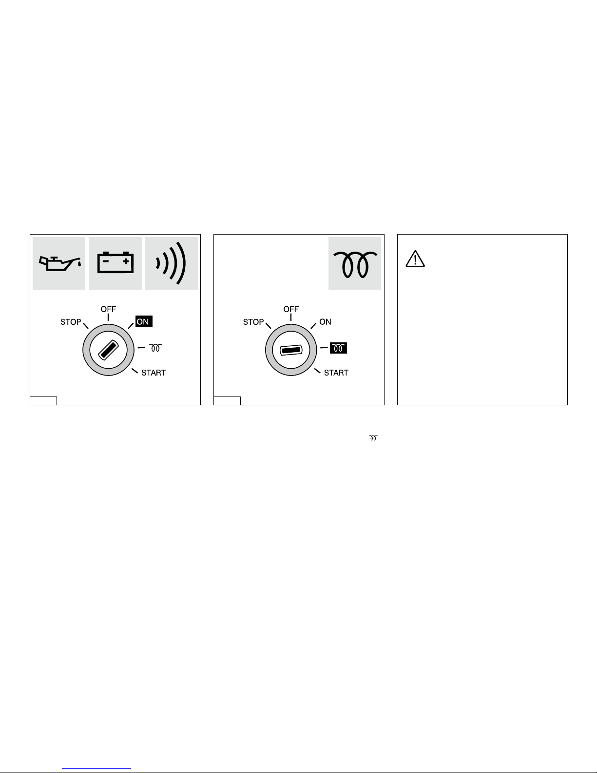
Turn the start key on the instrument panel
clock-wise; the warning lights for oil pressure and alternator will now light up and
the alarm buzzer will sound.
Pre-heating
Turn the key further clockwise to the ‘ ’
position; only the pre-heating indicator light will be lit now.
Hold the key in this position for about 2
seconds.
Starting
Use
18
VD00107 VD00108
WarNiNg
To prevent the glow plugs
from burning out, never exceed the
stated maximum pre-heating time.
Maximum pre-heating time is 3
seconds.
19
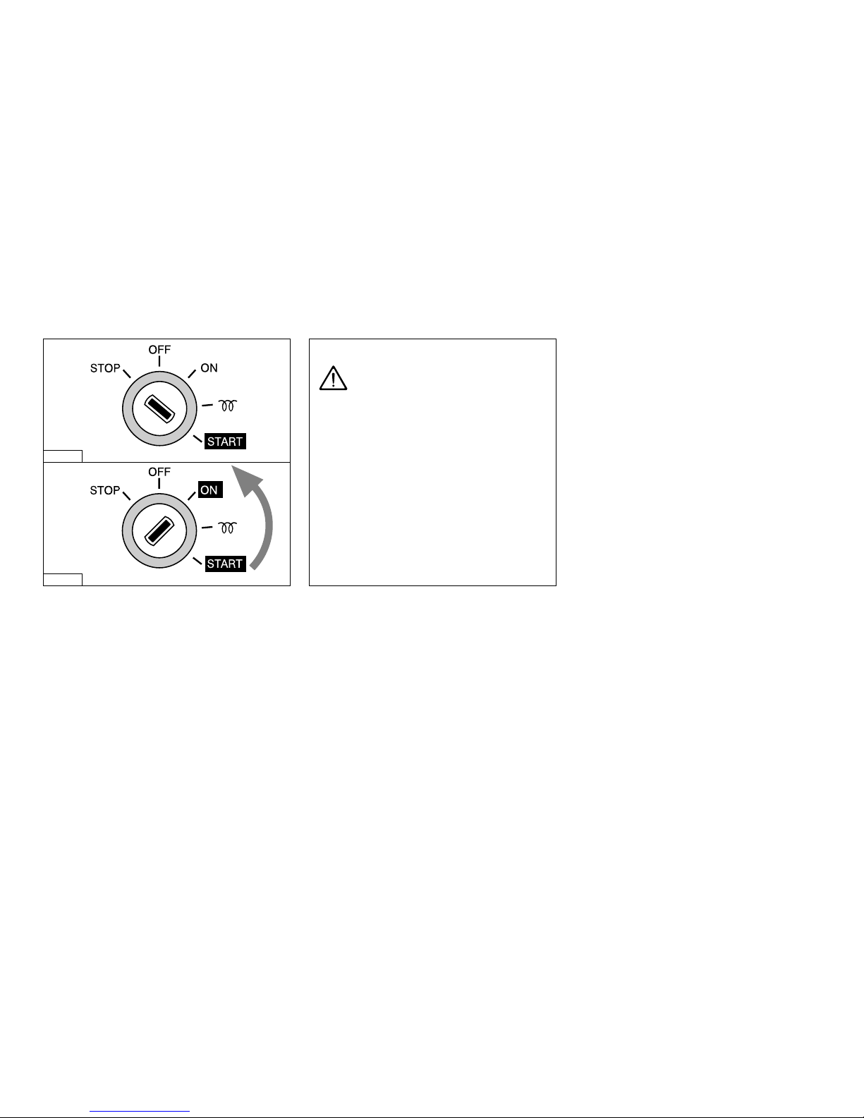
Starting
Now turn the key further to the ‘start’
position.
Release the key as soon as the engine
fires (the key will return to the ‘oN’ position) and throttle back.
Leave the key in this position while the
engine is running.
Check that the indicator lights for oil pressure and alternator are off. Cooling water
should now flow out of the exhaust; if this
is not the case, stop the engine immediately. Before submitting the engine to full
load it should be brought up to operating
temperature as quickly as possible by
running at 3/4 of maximum revs. Never
turn the main switch off while the engine
is running.
Use
Starting
WarNiNg
Release the key if the engine does
not fire within 10 seconds. Wait until
the starter motor has stopped running
completely before turning the key to
the ‘start’ position again. Never allow
the starter motor to run for more than
30 seconds consecutively.
VD00109
VD00110
The instrument panel is provided with the
following instruments (Depending of the
type of panel, see page 10 and 11).
WarNiNg
Never turn the key to the ‘start’ position
while the engine is running.
Doing so will damage the starter motor.
20
When the engine reaches operational temperature, exhaust gases should be colourless or light-blue. (In the winter, the low
temperatures will turn the exhaust emissions white.)
If black smoke is emitted from the exhaust,
this indicates that combustion is incomplete.
If white smoke is emitted, this indicates
combustion of oil forced up.
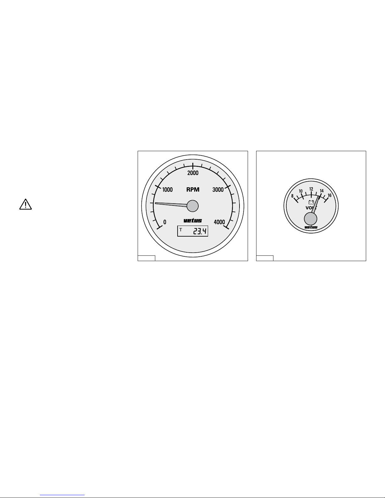
Tachometer
Indicating the number of revolutions per
minute of the engine.
Avoid idling for more than 10 minutes.
Also the number of running hours is indicated.
Idling speed,
VH4.65 : 850 rpm
VH4.80 : 850 rpm
Voltmeter
Indicating the battery voltage.
When the engine is running, the battery
voltage should be between 12 and 14
Volts.
With the engine stopped and the start key
in the first position, the voltmeter should
indicate 12 Volts.
Cruising
Use
VD00577 VD00578
21
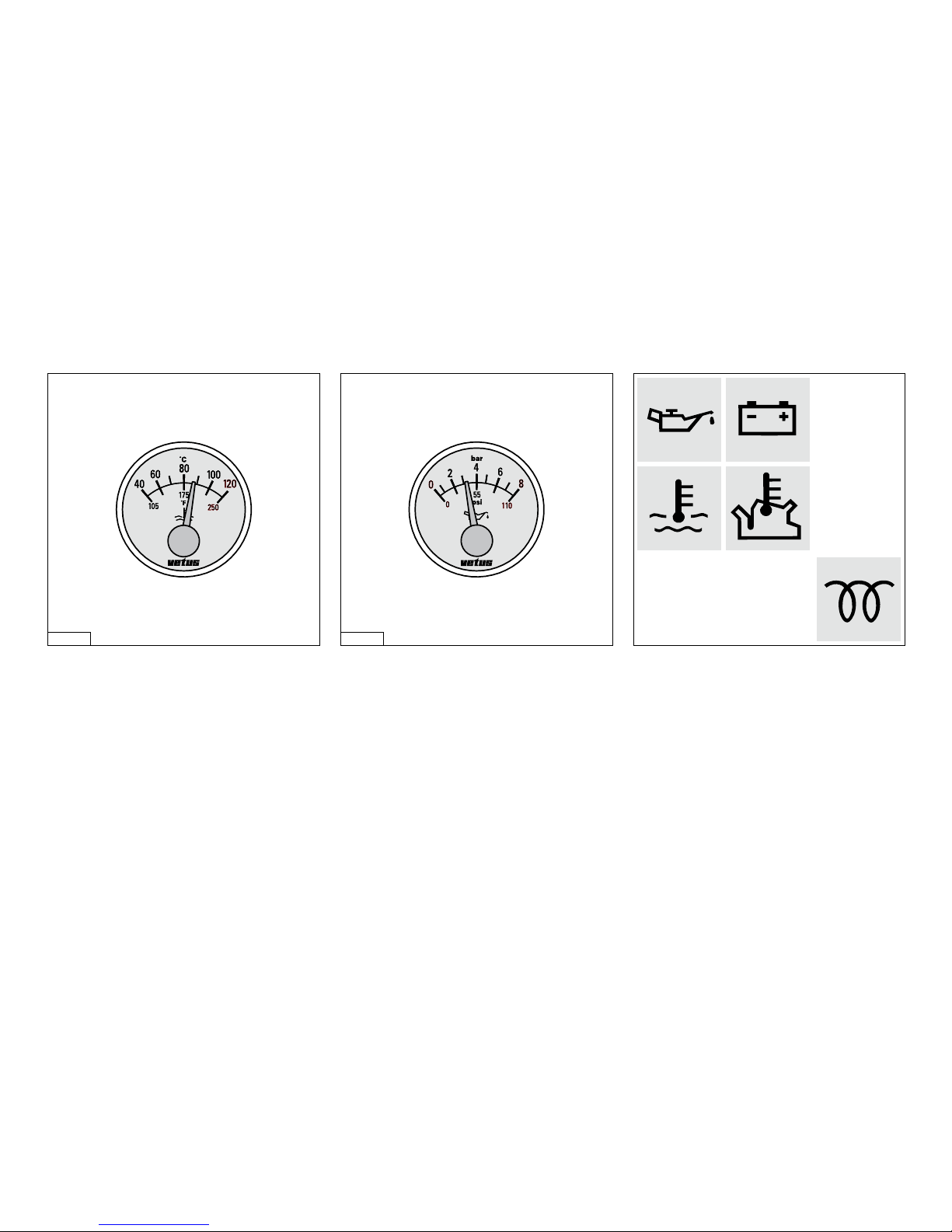
Temperature gauge
Indicating the temperature of the internal
cooling system.
The operating temperature is 76˚C - 85˚C.
In case the engine is overheated: turn off
the engine and establish the cause, see
fault finding table, page 59 .. 63.
Oil pressure gauge
With the engine at operating temperature,
the oil pressure is:
When idling: at least 0.8 bar (6 psi).
In case the oil pressure is too low: turn off
the engine and establish the cause, see
fault finding table, page 59 .. 63.
Warning lights
None of the five warning lights should light
up while the engine is running. Oil pressure, battery charging and temperature
indicator lights are all connected to an
alarm buzzer. If this alarm buzzer sounds
while running, stop tHe eNgiNe immedi-
ately!
Cruising
VD00663 VD00664
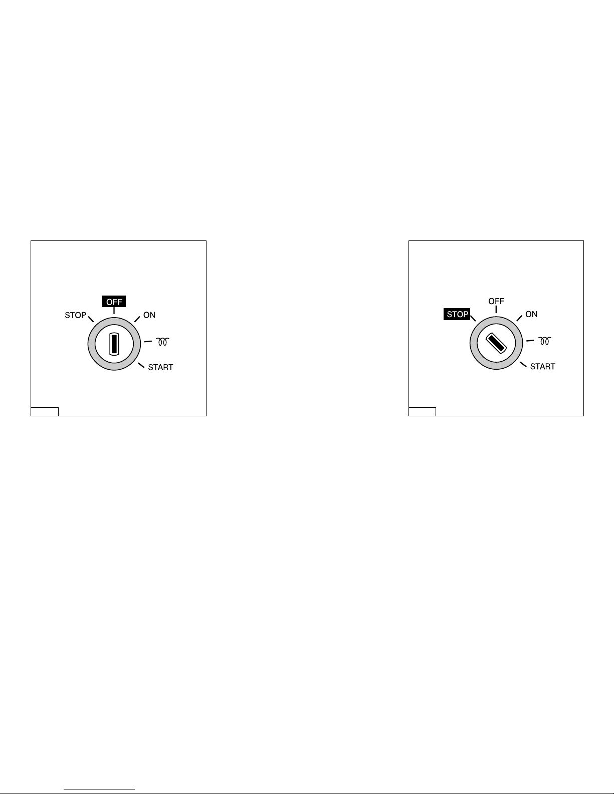
Stopping
Reduce engine speed to idle and shift the
gearbox to ‘Neutral’. Turn the key to the
left to the ‘off’ position.
If the engine is not to be used for some
time, it is recommended that the sea cock
is closed and the battery main switch
turned off.
Never stop the engine immediately after
it has been in operation for a long time.
Allow the engine to idle for a few minutes
before stopping.
N.B. The ‘stop’ position, left of the ‘off’
position on the control panel, has normally
no function for this engine.
When 2 control panels are connected to
one engine, the engine can always be
stopped by turning the key to the ‘stop’
position, no matter what the position is of
the key on the other panel.
Stopping
Use
22
VD00106 VD00105
 Loading...