


Operation manual
M2
M2.02
M2.06

ii

1
Operation manual
Please enter the serial numbers here.
These numbers should be quoted when inquiring about Customer Service, Repairs or Spare Parts (see page 6).
We reserve the right to make any changes without previous notice.
Copyright © 2012 Vetus N.V. Schiedam Holland
Serial numbers
Engine serial number Vetus:
Engine serial number Mitsubishi:
Gearbox serial number:
M2.02
M2.06
340802.01

2
Please read and observe the information given in this operation manual. This will enable
you to avoid accidents, preserve the manufacturer’s warranty and maintain the engine
in peak operating condition.
Make sure that the manual will remain intact
and damage is prevented. Keep the manual
away from humidity and heat.
Do not alter the content of the manual.
The manual is an integral part of the engine.
Hand over the manual tot the new owner if
boat or engine is being sold.
For the Guarantee Conditions, see the Vetus Diesel ‘Service and Warranty Manual’
(320199.06).
This engine has been built exclusively for the
application specied in the scope of supply and is to be used only for the intended
purpose. Any use exceeding that scope is
considered to be contrary to the intended
purpose. The manufacturer will not not assume responsibility for any damage resulting
therefrom. The risks involved are to be borne
by the user.
Use in accordance with the intended purpose also implies compliance with the conditions laid down by the manufacturer for
operation, maintenance and servicing. The
engine should only be operated, maintained
and serviced by persons which are familiar
with the former and the hazards involved.
The relevant accident prevention guidelines
and other generally accepted safety and
industrial hygiene regulations must be observed.
Unauthorized engine modications will invalidate any liability claims against the manufacturer for resultant damage.
Manipulations of the injection and regulating
system may also inuence the performance
of the engine, and its emissions. Adherence
to legislation on pollution cannot be guaranteed under such conditions.

3
Contents
1 Safety measures 4
Warning indications 4
Preventing re and explosion 5
Prevention of injury 6
When problems occur 8
2 Introduction 9
Data tag 10
Serial number 10
Cylinder numbering and direction
of rotation 11
Fuel pump seal 11
Identication of engine parts 12
Control panels 14
Control lever 15
3 First commissioning 16
4 Running-in 25
5 Use 26
General guidelines 26
Starting 28
Cruising 32
Stopping 34
6 Maintenance 36
Introduction 36
Maintenance schedule 38
Checking engine oil level 40
Checking and cleaning the raw
water strainer 41
Checking coolant level 42
Draining of water from the water
separator/fuel lter 44
Engine oil change 47
Battery, cables and connections 50
Gearbox oil level check 54
Fuel lter replacement 55
Bleeding, after fuel lter replacement 57
Changing the gearbox oil (Technodrive) 58
Changing the gearbox oil (ZFHurth) 59
Checking valve clearance 60
Checking the V-belt 62
Flexible engine mounts, hose connections and fasteners 63
Raw water pump inspection 64
Coolant replacement 66
Checking the starter motor and
alternator 70
Checking engine speed 71
Cleaning the heat exchanger 72
7 Winter storage procedure 76
8 Recommissioning after win-
ter storage 84
9 Troubleshooting 90
9 Troubleshooting 97
10 Technical data 100
Engine specications 100
Gearbox specications 103
Torque wrench settings 104
11 Operating media 105
Fuel 105
Lubricating oil 106
Coolant 109
12 Wiring diagram 110
13 Overall dimensions 112
14 Index 113

4
1 Safety measures
Danger
Indicates that great potential danger exists
that can lead to serious injury or death.
Warning
Indicates that a potential danger that can lead
to injury exists.
Caution
Indicates that the usage procedures, actions
etc. concerned can result in serious damage
to or destruction of the engine. Some CAUTION indications also advise that a potential
danger exists that can lead to serious injury or
death.
note
Emphasises important procedures, circumstances etc.
Symbols
Indicates that the relevant procedure
must be carried out.
Indicates that a particular action is for-
bidden.
Pass the safety precautions on to other people who will use the engine.
General rules and laws concerning safety
and accident prevention must always be observed.
Warning indications
The following warning indications are used in
this manual in the context of safety:
Warning indications

5
1 Safety measures
• Do not smoke if refuelling.
• Avoid spilling fuel on hot surfaces. Spilled
fuel must be cleaned up immediately.
• Do not use petrol or diesel to clean components but make use of good quality, noninammable, non-poisonous solvents that
are available from dealers.
• Always be alert to possible fuel or oil leakage!
If you discover a leak, take counter-measures immediately. If fuel or oil is spilled on
a hot engine, re can break out. This can
cause physical injury or damage to the
equipment.
• Do not ll the fuel tank while the engine is
running!
Only refuel with the engine stopped.
• Never put ammable materials in the vicinity of the engine!
• Keep the engine and engine compartment
clean!
Remove all inammable materials such as
fuel, oil and other litter before it builds up
in the vicinity of the engine.
• Connecting (emergency) extra starting battery
Proceed as follows when an extra starting
battery is used to jump start the engine:
- First connect the positive lead
- Lastly connect the earth cable (negative
pole) to the engine block
If this cable is connected in error to the
negative pole of the engine battery, a
spark can occur. The result of this could
be that explosive gas produced by the
battery explodes.
- Once the engine is started, rst remove the
earth cable.
Preventing re and explosion
Fire risk!

6
1 Safety measures
Prevention of injury
• The moving parts of the engine are dangerous. Never touch moving parts of the engine while it is running, to prevent cuts and
other injuries.
• Stop the engine before carrying out maintenance!
• Always stop the engine before topping up
or replacing fuel, oil or coolant.
• Before carrying out inspection or maintenance, the ignition key must be removed
and the main battery switch turned o.
• Satisfy yourself that everything is in order
before the engine is started again!
Make sure that no-one is working on or
close to the engine before you start it. Remove all foreign objects from around the
engine, such as litter, oil, tools and other
components that are not part of the engine.
• Install all protective covers!
To prevent injury, make sure that all protective covers and cover plates are replaced
over moving parts.
• Remove any tool used to turn the engine
over. If you leave this in position, serious
injury or damage to the equipment can result.
• NEVER open the cap of the expansion tank
when the engine is at working temperature.
• Only check the coolant level after the engine has been stopped and the ller cap
on the heat exchanger is cool enough to be
removed with bare hands.
• Never attempt to adjust the fan belt on a
running engine.

7
1 Safety measures
Prevention of injury
• Be careful with battery acid!
If battery acid comes in contact with the
eyes or skin, rinse the aected part immediately with copious amounts of water. If
battery acid comes in contact with the eyes,
rinse them out immediately with plenty of
water and consult a doctor.
• Be careful with antifreeze!
If you accidentally swallow antifreeze, make
yourself vomit and consult a doctor immediately. If antifreeze comes in contact with
your eyes, wash them out immediately with
plenty of water and consult a doctor.
• Make sure that you are wearing suitable
clothing before starting work!
For your own safety you will most likely
need special equipment – safety helmet,
eye protection, safety boots, safety goggles, heavy gloves, ear protectors etc. Use
them when necessary.
• Carry out maintenance procedures safely
by only using suitable tools.
• Exhaust gases
Do not start the engine if the exhaust system is not connected.

8
When the engine stops suddenly:
If the engine stops suddenly, do not start it
again immediately. Track down the cause and
carry out the necessary repairs before you
start the engine again. If you do not do this,
serious engine problems can develop.
If the oil pressure is too low:
Stop the engine immediately and check the
lubrication system. Running an engine with
low oil pressure can cause bearing and other
parts to seize.
lf the engine overheats:
If the engine should overheat, do not switch
it o immediately. If an overheated engine is
stopped suddenly, this can cause the coolant
temperature to rise rapidly and moving parts
to seize. First let the engine run in neutral to allow the hot parts of the engine to cool down,
stop the engine and allow it to cool, and then
gradually top up the coolant. Remember:
adding coolant to an overheated engine can
cause damage to the cylinder head.
If the fan belt is broken:
Immediately stop the engine. If an engine is
used with a broken fan belt, this can lead to
the engine overheating, which in turn can
cause coolant to spray out of the expansion
tank.
If the engine behaves strangely:
Stop the engine or reduce the speed as far as
possible.
Do not use the engine again until the cause of
the defect has been solved.
1 Safety measures
When problems occur

9
Vetus diesel engines are designed for pleasure craft. Consequently, a wide range of variants are oered to meet the requirements of
specic cases.
Your engine is appropriately equipped for
your vessel, which means that not necessarily
all components described in this manual are
mounted to your engine.
We have endeavoured to highlight any dierences so that you will able to locate the operating and maintenance instructions relevant
to your engine quickly and easily.
Please read this manual before starting your
engine and always observe the operating and
maintenance instructions.
We are available to help with any additional
inquiries.
Sincerely,
Vetus n.v.
2 Introduction
Dear customer,

10
2 Introduction
Data tag
Serial number
1 Engine data tag
The Vetus engine serial number and performance data are printed on the engine data
tag.
Model and engine serial number must be given when ordering spare parts.
2 Engine data tag location
The type plate is positioned as shown.
3 Engine serial number
The Mitsubishi engine serial number is
stamped on the fuel injection pump. (arrow)
VD01036
VD01044
VD01035
Lead seal
Maximum speed
adjustment screw
11
2 Introduction
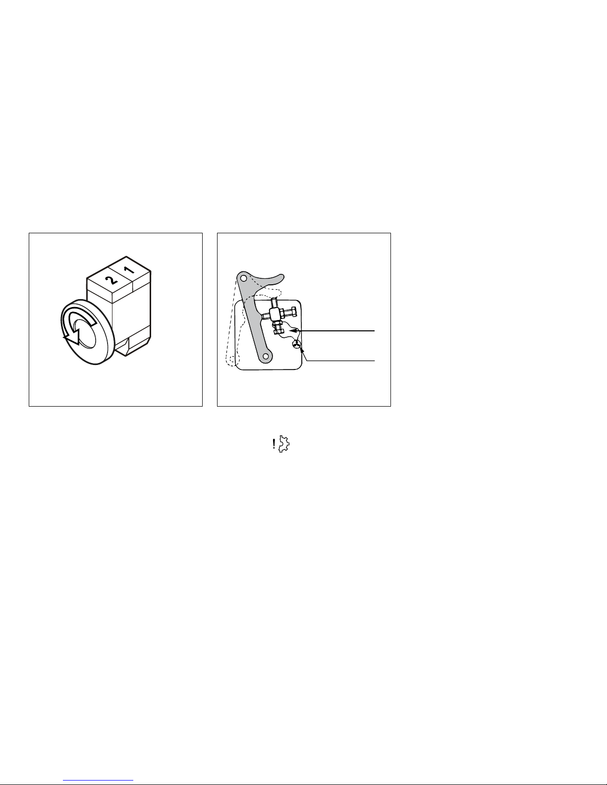
Cylinder numbering and direction of rotation
Fuel pump seal
4 Cylinder numbering and direction of
rotation
Cylinder numbering
Cylinders are numbered consecutively, beginning at the front end.
Direction of rotation
The direction of rotation is viewed towards
the ywheel counter clockwise.
5 Fuel pump seal
Caution
Breaking the seals on the regulator to alter
the settings of maximum rpm and maximum
injector volume may only be carried out by
authorised Vetus Service personnel.
Breaking the seals and altering the settings
can lead to:
- Accelerated wear of engine components.
- Increased fuel and oil consumption.
- Incorrectly adjusted injector volume and
poor engine performance.
- Breaking emission regulations.
VD00930
VD00922

1235 46789
1 171614 1513121110 18
12
2 Introduction
Identication of engine parts
Service side
1 Oil ller cap
2 Raw water inlet ø 20 mm
3 Raw water pump
4 Oil dipstick
5 Manual operation of fuel supply pump
6 Oil lter
7 Water separator/fuel lter drain plug
8 Water separator/Fuel lter
9 Connection for gearbox push-pull cable
10 Fuse
11 Electrical system connector box
12 Fuel return pipe connection ø 8 mm
13 Air inlet silencer
14 Water separator/fuel lter air bleed
nipple
15 Manual operation of electric stop
16 Fuel supply pipe connection ø 8 mm
17 Fuel lift pump
18 Connection for throttle push-pull cable
VD01253

19
20
212223
30 31, 2628 2925, 26, 2724
32
33
13
2 Introduction
Identication of engine parts
Starter side
19 Gearbox
20 Gearbox drain plug
21 Gearbox oil dipstick/ller cap
22 Starter motor
23 Alternator
24 V-belt
25 Connection for extra expansion tank
(Keel cooling model only)
26 Calorier connection
27 Cooling system air bleed nipple
28 Filler cap for cooling system
29 Expansion tank
30 Heat exchanger
31 Cooling system drain plug
32 Airvent connection
33 Exhaust injection bend ø 40 mm
VD01254

5
3
7
8
6
4
9
1 2
5
3
7
8
6
4
14
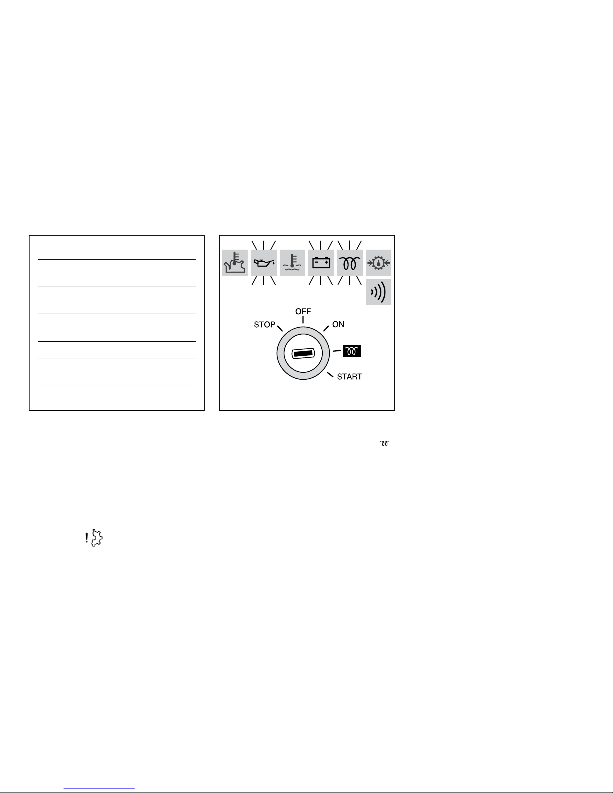
8 Indicator light pre-heating
9 Warning light gearbox low oil pressure
[1]
1 Tachometer/Operating hours counter
2 Voltmeter
3 Starter pre-heat switch/lock
4 Warning light high raw water temperature
5 Warning light low oil pressure
6 Warning light high coolant temperature
7 Warning light battery charging
2 Introduction
Control panels
Basic panel, model 22
Fly-bridge panel, excl. voltmeter, model 21
Sailingboat panel, model 10
VD00576
VD00575
[1]
This is an option, not tted as standard.

Single lever control
handle for two engines
Single lever control
handle for 1 engine
neutral
gearbox reverse gearbox forward
forward throttlereverse throttle
15
2 Introduction
Control lever
6 Operating lever
Operating lever for 1 or 2 engines. The control lever works as shown in the dia-
gram.
Starting from neutral put the engine in ahead
or astern by moving the lever 35° forwards or
backwards.
The throttle lever operates at an angle of 60°
forwards and 60° reverse.
VD00788

OIL OIL
16
3 First commissioning
1 Commissioning the engine
Before starting the engine for the rst time,
the following procedures must be carried out:
2 Filling with engine oil
As a rule engines are delivered empty of oil.
• Fill the engine with oil through the ller
neck on top of the valve cover.
For quantity and oil specication see page
102 and 106.
• Check the oil level with the dipstick, see
page 40.
A second oil lling cap is located at the distribution cover.
Engine Oil
2.4 litres 15 W40
(4.2 Imp. pt, 5.1 US pt)
API: CF4, CG4, CH4, CI4
ACEA: A3/B3, A3/B4, E7
For example:
- Vetus Marine Diesel Engine Oil 15W40
- Shell Rimula R4 L 15W40
VD01013
VD01002

27
17
OIL OIL
17
3 First commissioning
3 Filling gearbox with oil
• Fill the gearbox with oil.
• Check the oil level with the dipstick, see
page 42.
Technodrive:
type TMC40P : 0.2 litres, ATF
[1]
(0.35 Imp. pt, 0.42 US pt)
type TMC60A : 0.6 litres, ATF
[1]
(1.05 Imp. pt, 1.25 US pt)
ZF Hurth:
type ZF10M : 0,42 litres ATF
[1]
(0.73 Imp. pt, 0.89 US pt)
Vetus engines are normally equipped
with Technodrive or ZF-Hurth gearboxes.
In case your engine is equipped with
another brand of gearbox follow the instructions given in the supplied owners
manual.
[1]
ATF :Automatic Transmission Fluid;
Transmissie olie type A, Sux A.
[1]
ATF :Automatic Transmission Fluid;
Transmissie olie type A, Sux A.
VD01033
VD01034

1 cm
(
3
/8”)
COOLANT
17
COOLANT
18
3 First commissioning
4 Filling the cooling system,
interCooling
,
• Remove the cap of the ller neck on the top
of the heat exchanger housing.
• Remove the bolt from the upper side of the
thermostat cover, so that air can escape
from the cooling system.
• Fill the cooling system.
Use a mixture of 40% antifreeze (ethyleneglycol based) and 60% tap water or use a special coolant.
For specications see page 109.
The level of the coolant must be approx. 1 cm
(3/8”) below the lower edge of the ller neck.
Bleeding will take place automatically during
lling!
• Replace the ller cap.
• Reinstall the bolt in the thermostat cover..
Coolant quantity
: 2.2 litres
(3.9 Imp. pt, 4.6 US pt)
VD01005
VD01004
VD00158
note
If a water heater is connected to the engine,
see page 20 and 21.
Caution
Never ll the cooling system with sea water or
brackish water.

2
1
DO NOT OPEN
1.5 bar
2
1
DO NOT OPEN
1.5 bar
19
3 First commissioning
5 Filling the cooling system,
keel Cooling
• Remove the cap ‘
do not open
’ (1) of the
ller neck on the top of the heat exchanger
housing.
• Fill the cooling system.
• Reinstall the ller cap ‘
do not open’
.
• Remove the pressure cap (2) of the extra
expansion tank.
• Top up the extra expansion tank to the minimum level.
• Reinstall the pressure cap (2).
Use a mixture of 40% antifreeze (ethyleneglycol based) and 60% tap water or use a special coolant.
For specications see page 109.
note
If a water heater is connected to the engine,
see page 20 and 21.
VD00929
VD00925
Caution
Never ll the cooling system with sea water or
brackish water.
VD00932

2
1
DO NOT OPEN
1.5 bar
20
3 First commissioning
6 Filling coolant system, if a water heater
is connected (1)
The
highest
point of the water heater is situ-
ated at a
loWer
level than the expansion tank
for the ship’s engine.
The water heater will be filled and bled auto-
matically during lling of the cooling system.
• Remove the ‘
do not open
’ cap (1) and ll the
cooling system via the ller neck.
• Add coolant into the expansion tank (2) until minimal level has been reached.
Use a mixture of 40% antifreeze (ethyleneglycol based) and 60% tap water or use a special coolant.
For specications see page 109.
VD00895
VD00925
Caution
Never ll the cooling system with sea water or
brackish water.

2
3
1
DO NOT OPEN
1.5 bar
21
3 First commissioning
7 Filling coolant system, if a water heater
is connected (2)
The
highest
point of the water heater is situ-
ated at a
higher
level than the expansion tank
for the ship’s engine.
The water heater will
not
be filled and bled
automatically during lling of the cooling
system.
• Fill the cooling system via the expansion
tank (2).
• Open valve (3) during lling and bleeding
the system.
Use a mixture of 40% antifreeze (ethyleneglycol based) and 60% tap water or use a special coolant.
For specications see page 109.
VD00896
VD00925
note
• Remember to close valve (3) after lling the
system.
Caution
Never ll the cooling system with sea water or
brackish water.

Neutral
(No throttle, gearbox
not engaged)
FUEL
22
3 First commissioning
8 Fuel
• Ensure that the fuel tank is lled with diesel
fuel.
Use only clean, water-free, commercial approved diesel fuel.
For fuel grade see page 105.
• Bleed the fuel system, see page 45.
9 Other preparations
• Check that the battery is charged and check
the battery cable connections.
• Set the main switch to position ‘
on
’.
• Open the sea cock.
• Check that the gearbox control lever is set
to ‘
neutral
’.
VD
Warning
Never ll the fuel tank while the engine is
running. Do not spill fuel. Prevent unnecessary pollution.
VD00002
VD00789

OIL
23
3 First commissioning
10 Test run
• Start the engine.
How to start the engine and what to check
before, during and immediately after starting is described on page 28 and further.
• Allow the engine to test run for about 2
minutes at idling speed .
• Stop the engine
• Check the oil level. If necessary top up to
the indicated level.
• Start the engine.
• Allow the engine to test run for about 10
minutes at idling speed.
• Stop the engine.
• Check that the engine and all connections
(fuel, coolant and exhaust) for leaks.
VD01001
VD01046
Caution
Stop the engine immediately if it makes
any strange noises, vibrates excessively or
if black smoke comes out of the exhaust!

24
3 First commissioning
11 Bleeding
The cooling system must be bled as soon as
the engine has reached normal working temperature.
• Open the cap on the ller neck.
• Vary the revolutions between idling and
2000 rev/min.
• Add coolant if necessary.
• Replace the cap on the ller neck.
• Check the coolant temperature.
12 Sea trial
• Check the operation of the remote control.
• Carry out a sea trial
VD00663
VD01003
VD00791

25
4 Running-in
In order to ensure a long life for your engine, please observe the following for the
first 50 operating hours:
• Allow the engine to reach operating temperature before applying a load.
• Avoid fast acceleration.
• Do not allow the engine to run faster
than 3/4 of maximum RPM.
After the rst 50 operation hours carry out the
following maintenance:
• Drain water from fuel lter, see page 44.
• Engine oil change, see page 47.
• Replace oil lter, see page 48.
• Replace fuel lter, see page 55.
• Change gearbox oil (Technodrive), see
page 58.
• Change gearbox oil (ZF Hurth), see page 59.
• Check V-belt, see page 62.
• Check exible engine mounts, see page 63.
• Check engine for leaks, see page 63.
• Check tightness of all fasteners, bolts and
nuts, see page 63.

26
5 Use
General guidelines
General guidelines for use
Implementing the following recommendations will result in longer life and better performance and more economical operation of
your engine.
• Carry out the maintenance described regularly, including the ‘Daily procedures before
starting’.
• Use anti-freeze in the engine coolant all
year long, this helps prevent corrosion as
well as protecting against frost damage. For
specications see page 109.
• Never run the engine without a thermostat.
• Use a good quality lubricating oil. For speci-
cations see page 106.
• Use a good quality diesel fuel that is free of
water and other pollutants.
• Always stop the engine immediately if one
of the warning lamps for oil pressure, high
coolant temperature, high raw water temperature
[1]
or battery charging lights up.
• Always follow the safety advice, see page 4.
[1]
Only engines with intercooling.

27
5 Use
General guidelines
note
First commissioning
Follow the instructions given for ‘First commissioning’ on page 16 and further if the engine is being commissioned for the rst time.
After repair work:
Check that all guards have been replaced and
that all tools have been removed from the engine.
When starting with pre-heating, do not use
any other substance (e.g. injection with ‘Easy
Start’). Doing so could result in an accident.

half throttle,
gearbox not engaged
28
5 Use
Starting
Before starting, always check the following
points:
• Engine oil level.
• Coolant level.
• Sea cock open.
• Main switch ‘on’.
• Gearbox in ‘
neutral
’ position.
1 Control lever
Set the control lever to ‘half throttle’ without
engaging the gearbox.
2 Switching on
• Turn the start key on the instrument panel
clock-wise; the warning lights for oil pressure and alternator will now light up and
the alarm buzzer will sound.
Warning
Never start the engine with the fuel injection pump removed. Disconnect battery.
VD00923
VD00107
29
5 Use
Starting
3 Pre-heating
The ideal pre-heating time depends on ambient temperature; the lower the ambient
temperature, the longer the pre-heating time
required. See table.
• Turn the key further clockwise to the ‘
’
position.
While pre-heating takes place the preheating
indicator light will be on and the alarm buzzer
o.
• Hold the key in this position for about 6 seconds.
Ambient Tem-
perature
Pre-heating time
Above + 5°C
(41°F)
about 6 seconds
+5°C to -5°C
(+41°F to +23°F)
about 12 seconds
Below -5°C (23°F) about 18 seconds
Maximum pre-
heating time
1 minute
VD00108
Caution
To prevent the glow plugs from burning out,
never exceed the stated maximum pre-heating time.

30
5 Use
Starting
4 Starting
Now turn the key further to the ‘
start
’ posi-
tion.
Release the key as soon as the engine res
(the key will return to the ‘on’ position) and
throttle back.
Leave the key in this position while the engine
is running.
Caution
Release the key if the engine does not re
within 10 seconds.
Let the starter motor cool for 30 seconds before turning the key to the ‘
start
’ position
again.
VD00110
VD00109

31
5 Use
Starting
Check that the indicator lights for oil pressure
and alternator are o.
Cooling water should now ow out of the exhaust; if this is not the case, stop the engine
immediately
[1].
Let the engine run for 5 to 10 minutes in neutral. A good warm up is essential to ensure
maximum lifetime and good performance.
never turn the main switch o while the engine is running.
Caution
Never turn the key to the ‘
start
’ position
while the engine is running.
Doing so will damage the starter motor.
VD00629
[1]
Only engines with intercooling.

32
5 Use
Cruising
The instrument panel is provided with the following instruments (Depending of the type of
panel, see page 17).
5 Tachometer
Indicating the number of revolutions per
minute of the engine.
Also the number of running hours is indicated.
Idling speed : 850 rpm
Warning
Avoid idling for more than 10 minutes.
This can lead to carbon deposits in the combustion chambers and incomplete combustion of fuel.
VD00577
33
5 Use
Cruising
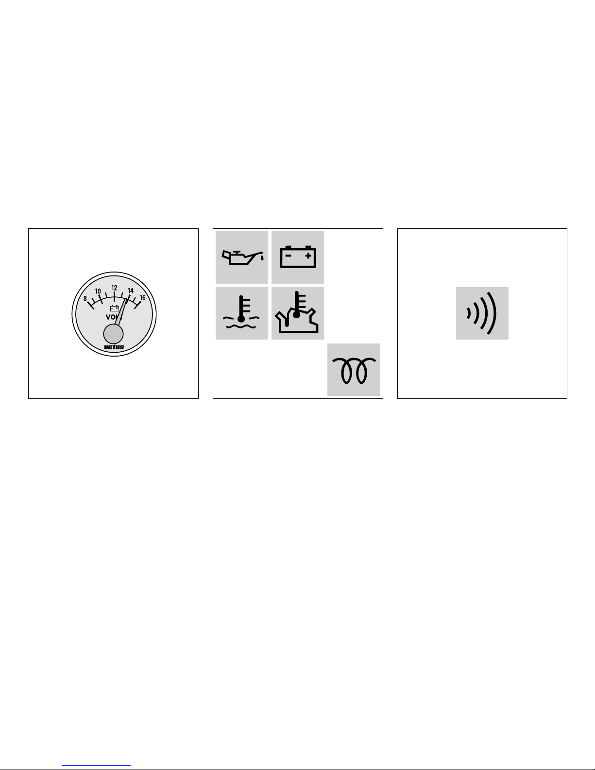
6 Voltmeter
Indicating the battery voltage.
When the engine is running, the battery voltage should be between 12 and 14 Volts.
With the engine stopped and the start key in
the rst position, the voltmeter should indicate 12 Volts.
7 Warning lights
None of the ve warning lights should light
up while the engine is running.
8 Alarm buzzer
Oil pressure, battery charging and temperature indicator lights are all connected to an
alarm buzzer. If this alarm buzzer sounds
while running, Stop the engine immediately!
VD00578

Neutral
34
5 Use
Stopping
9 Stopping
• Reduce engine speed to idle and shift the
gearbox to ‘Neutral’.
• Turn the key entirely to the left, through
the ‘
oFF
’ position.
• When the engine has stopped, turn the key
to the ‘
oFF
’ position.
VD00105
VD00790
VD00106
note
Never stop the engine immediately after it
has been in operation for a long time. Allow
the engine to idle for a few minutes before
stopping.
note
If the engine is not to be used for some time,
it is recommended that the sea cock is closed
and the battery main switch turned o.

35
5 Use
Stopping
10 Stopping on the engine itself
On the engine itself stopping is possible by
pressing the black button on the fuel injection pump.
If the fuel supply is not shut o by the electrically operated fuel solenoid stopping of the
engine can be done this way.
VD01037

36
6 Maintenance
Introduction
Introduction
The following guidelines should be observed
for daily and periodic maintenance. Perform
each function at the indicated time interval.
The intervals stated are for normal operational conditions. Service the unit more frequently under severe conditions.
Failure to carry out maintenance can result in
faults and permanent damage to the engine.
No claim can be made on the Guarantee if
maintenance has been neglected.

37
6 Maintenance
Introduction
Keep record of the following information
in the logbook and/or the ‘Service and Warranty Manual’:
- Total engine hours (reading engine hour
counter).
- Amounts of oil, fuel and coolant needed for
topping up.
- The dates and intervals at which the oil and
coolant are changed.
- Oil pressure and coolant temperature.
- Parts on which maintenance is conducted
and type of maintenance (adjustment,
repair or replacement), and the results of
each procedure.
- Changes in operating conditions, such as
‘Exhaust gas became black’, etc.

38
6 Maintenance
Maintenance schedule
Danger
Stop the engine before carrying out any maintenance work
Every 10 hours or daily, before starting page
Check engine oil level 40
Check water strainer 41
Check coolant level 42
After the rst 50 hours page.
Drain water from fuel lter 44
Engine oil change 47
Replace oil lter 48
Check gearbox oil level 54
Replace fuel lter 55
Check V-belt 62
Check exible engine mounts 63
Check engine for leaks 63
Check tightness of all fasteners, bolts and nuts 63
Every 100 hours, at least once every year page
Drain water from fuel lter 44
Engine oil change 47
Replace oil filter 48
Battery, cables and cable connections 50
Check gearbox oil level 54
Every 500 hours, at least once every year page
Replace fuel filter 55
Change gearbox oil (Technodrive) 58
Change gearbox oil and replace filter (ZF Hurth) 59
Check valve clearance 60
Check V-belt 62
Check flexible engine mounts 63
Check engine for leaks 63
Check tightness of all fasteners, bolts and nuts 63

39
[1]
Consult the service manual, work to be carried out by a Vetus Mit-
subishi dealer.
6 Maintenance
Maintenance schedule
Danger
Stop the engine before carrying out any maintenance work
Every 500 hours
page
Check glow plugs
[1]
Every 1000 hours, at least once every 2 years page.
Raw water pump inspection 64
Replace coolant 66
Every 1000 hours page.
Check starter motor 70
Check alternator 70
When required page
Bleeding fuel system 45
Check idle rpm 71
Cleaning heat exchanger 72

OIL OIL
40
6 Maintenance
Checking engine oil level
Daily, before starting.
1 Check oil level
• Turn the engine o.
The dipstick is located on the starboard side
of the engine.
2 Oil level
The oil level must be at or near the upper
mark on the dipstick
[1]
.
• If necessary top up with the same brand
and type of oil.
3 Topping up oil
The oil lling cap is on top of the the valve
cover,.
A second oil lling cap is located at the distrubution cover, see page 16.
VD00155
VD01001
VD01013
[1]
The dierence between the two oil level
marks is: 1.0 litres (1.8 Imp. pt, 2.1 US pt)

41
6 Maintenance
Checking and cleaning the raw water strainer
Daily, before starting.
4 Checking the raw water strainer
• Check daily whether there is any dirt in the
raw water strainer.
5 Cleaning the strainer
• Close the seacock before removing the lid
of the water strainer.
• Clean the raw water strainer as often as is
necessary, depending on the pollution of
the waterways, but at least once every 6
months. A clogged raw water strainer will
result in excessive temperatures or overheating of the engine coolant.
• Check the sealing between the lid and
housing after cleaning and re-assembling
the strainer. An improperly sealed lid will result in air sucked in by the sea water pump
which again will result in overheating of the
engine.
VD00802
VD00801
note
Only engines with intercooling!

1 cm
(3/8”)
COOLANT
COOLANT
42
6 Maintenance
Checking coolant level
Daily, before starting.
6 Checking coolant level
• Check the coolant level in the header tank.
This has to be checked when the engine is
cold.
• Remove the cap of the ller neck on the
heat exchanger.
7 Coolant level
The level of the coolant must be approx. 1 cm
(3/8”) below the lower edge of the ller neck.
8 Topping up coolant
• If necessary, top up.
The internal cooling system can be lled with
a mixture of anti-freeze (40 %) and tap water
(60 %) or with a special coolant. For specication, see page 109.
VD00158
VD01003
VD01004
Warning
Never open the cap on the header tank when
the engine is at operating temperature.
note
For a keel-cooled version, see page 19.
If a water heater is connected, see page 20
and 21
Caution
Never ll the cooling system with sea water or
brackish water.

43
6 Maintenance
Checking coolant level
Daily, before starting.
• When topping up coolant, remove the
bolt from the upper side of the thermostat cover, so that air can escape from
the cooling system.
VD01005
44
6 Maintenance
Draining of water from the water separator/fuel lter
Every 100 operating hours.
Danger
Do not smoke when draining o water and
sediment. Keep ame and sources of ignition
out of the area. Remove spilled fuel and litter
before you start the engine.
9 Empty fuel lter
• Open the drain plug at the lower side of the
lter.
• Drain the water and close the drain plug.
10 Empty water separator
Empty the separately installed water separator/fuel lter:
• Open the drain plug at the lower side of the
lter.
• Drain the water and close the drain plug.
Note : The water separator is not within the
scope of supply but installation is required!
VD00803
VD01006

45
6 Maintenance
Draining of water from the water separator/fuel lter
Every 100 operating hours.
11 Bleeding
After the water separator/fuel lter has been
drained, the air has to be bled from the fuel
system
The fuel system is self-bleeding; but manual
bleeding the system is recommended.
• Open the two bleeding nipples.
- One (1) bleeding nipple is located at the
lter.
- A second bleeding nipple is located at the
fuel injection pump.
• Prime the fuel system by pumping the fuel
pump.
• Close the bleeding nipples when all air has
escaped.
N.B. It is necessary to operate the lever over
the full stroke for proper operation.
141013
VD001008
VD01007
VD01009

46
6 Maintenance
Draining of water from the water separator/fuel lter
Every 100 operating hours.
12 Start the engine
• Operate the starter switch until the engine
res; release the starter switch if the engine
does not re within 20 seconds.
• Wait until the starter motor has stopped
before making a new attempt to start the
engine.
• Repeat the above if the engine cuts out after a short time.
VD00109

47
6 Maintenance
Engine oil change
Every 100 operating hours.
13 Engine oil change
Change the engine oil every 100 hours of
operation (together with engine oil lter replacement).
If the engine runs less than 100 hours during
the year the oil should be changed at least
once a year.
Run the engine for a few minutes before
changing the oil; warm oil can be pumped
out more easily.
Change the oil with a switched o engine at
operation temperature. (Lube oil temperature
approx. 80°C (176°F).)
Danger
Be aware of the risk of skin burning during
draining the hot oil! Used oil must be collected in a container for proper disposal according to laws and regulations.
Warning
Never use additives.
This could cause damage to the engine which
is not covered by the guarantee.

48
Warning
The engine oil must be disposed in
accordance with the applicable en-
vironmental regulations.
6 Maintenance
Engine oil change
Every 100 operating hours.
14 Draining the oil
• Remove the dipstick; insert the suction
hose of the supplied sump pump in the
dipstick tube.
• Push down the pump handle quickly and
pull it up slowly.
• Pump the sump empty.
• After draining remove the suction hose of
the sump pump out of the dipstick tube.
15 Removing the oil lter
• Unscrew the oil lter, with a commercially
available tool.
Catch any dripping oil.
VD01026
VD01010
Danger
Beware of burns from hot oil.

49
6 Maintenance
Engine oil change
Every 100 operating hours.
16 Oiling the oil seal
• Clean the contact surface of the gasket.
• Lubricate the oil seal of the new lter ele-
ment with clean engine oil.
17 Oil lter installation
• Install the lter in accordance with the instructions printed on the lter element
housing.
18 Relling with oil
• Rell the engine with new oil (for specication see page 106) through the ller opening in the valve cover.
• Operate the engine at idling speed for a
short period of time. Check for oil leaks
whilst the engine is running. Stop the engine. Allow 5 minutes for the oil to return
to the sump. Check the oil level with the
dipstick.
VD01011
VD00124
VD01013
amount of oil (oil filter inCl.)
: 2.9 litres
(5.1 Imp. pt, 6.1 US pt)
oil filter, art.Code
: STM0051

50
6 Maintenance
Battery, cables and connections
Every 100 operating hours.
Warning notes and safety regulations for
working with batteries
Wear eye protection.
Keep children away from acid and batteries.
Explosion hazard:
A highly-explosive oxyhydrogen gas
mixture occurs when charging batteries, therefore:
Fires, sparks, naked ames and smoking are prohibited:
• Avoid causing sparks when dealing
with cables and electrical equipment, and beware of electrostatic
discharges.
• Avoid short-circuits.
Pb
Corrosive hazard:
Battery acid is highly corrosive, therefore:
• Wear protective gloves and eye protection.
• Do not tilt battery, acid can escape
from the degassing openings or
vents.
First aid:
• Rinse o acid splashed in the eyes
immediately for several minutes
with fresh water. Then consult a
doctor immediately.
• Neutralize acid splash on skin or
clothes immediately with acid neutralizer (soda) or soap suds and
rinse with plenty of water.
• If acid is consumed, consult a doctor immediately.
Warning note:
• Do not place batteries in direct daylight without protection.
• Discharged batteries can freeze up,
therefore store in an area free from
frost.
Disposal:
Hand in old batteries at a collection
point.
Keep the batteries upright and do not
tip during transport and storage to
prevent acid leaking out.
Never dispose of old batteries as domestic waste.
Careful! Metal parts of the battery will
are always live so never lay objects or
tools on the battery.

51
6 Maintenance
Battery, cables and connections
Every 100 operating hours.
19 Battery, battery connections
Keep battery clean and dry.
• Remove battery cables (negative rst).
• Clean battery posts (+ and −) and clamps
and grease with acid-free and acid-resistant
grease.
Ensure that clamps make good contact after
reassembling.
• Hand tighten the bolts only.
VD00117

1
Vetus maintenance-free batteries
GREEN DOT
ALL DARK
CLEAR
52
6 Maintenance
Battery, cables and connections
Every 100 operating hours.
20 Checking specic gravity
Every Vetus Maintenance-free battery has a
hydrometer (1) built into the cover.
Visual inspection of the hydrometer will show
one of three conditions:
21 Hydrometer operation
Green dot visible:
State of charge 65 % or more.
Dark:
State of charge less than 65 %. Recharge immediately.
Clear or light yellow:
Electrolyte level low.
In case of low level, caused by overcharging
the battery for a long period of time with a
voltage too high, replace battery. Check alternator and/or voltage regulator.
VD00121, VD00122, VD00123
VD00118

Conventional batteries
Conventional batteries
53
6 Maintenance
Battery, cables and connections
Every 100 operating hours.
22 Checking electrolyte level
For conventional batteries it is required to
check the electrolyte level regularly. Remove
vent caps (taking care no spark or open ame
is nearby) and inspect the level. Fluid should
be 10 to 15 mm (
3
/8” to 5/8”) above top of all
plates. If necessary top up with distilled water.
Replace vent caps and charge the battery for
15 minutes at 15 - 25 Amps to mix electrolyte.
23 Checking specic gravity
Measure the electrolyte specic gravity of the
individual cells with a commercial hydrometer. The hydrometer reading (see table) indicates the state of charge. Hydrometer reading
of all cells should be at least 1.200 and show
less than 0.050 between high and low. If not,
recharge or replace battery.
Specic
gravity
State of
charge
1,.8 kg/l 100%
1.20 kg/l 50% recharge
1.12 kg/l 10%
recharge
immediately
During checking the temperature of the electrolyte should preferably be 20°C (68°F).
Measuring the specic gravity shortly after
water has been added results in an incorrect
measurement. First charge the battery to mix
the added water thoroughly.
VD00120
VD00119

54
25 Oil level check (ZF-Hurth)
6 Maintenance
Gearbox oil level check
Every 100 operating hours.
Vetus engines are normally equipped with
Technodrive or ZF-Hurth gearboxes. Consult
the supplied Owners Manual for more details
about care and maintenance. In case your
engine is equipped with another brand of
gearbox follow the instructions given in the
supplied owners manual for changing oil and
other care and maintenance.
24 Oil level check (Technodrive)
• Take the dipstick out of the gearbox housing by pulling or unscrewing.
• Check the oil level by lowering the dipstick
(cleaned) into the hole.
The oil level must between the two marks on
the dipstick
• If necessary top up by pouring oil into the
ller hole or the dipstick hole.
For oil type and specication see page 108.
17
VD01038
VD01032

55
6 Maintenance
Fuel lter replacement
Every 500 operating hours.
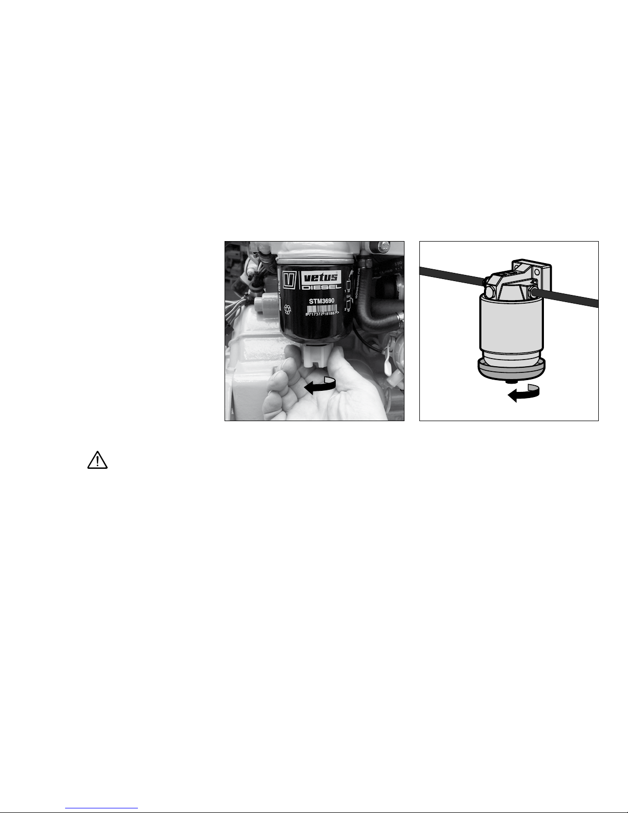
26 Fuel lter removal
The fuel lter is to be replaced as a unit.
• Close the fuel stopcock.
• Remove the fuel lter, use a lter wrench.
Catch any fuel.
Danger
Keep naked ames away when working on
the fuel system. Do not smoke!
VD01017

56
6 Maintenance
Fuel lter replacement
Every 500 operating hours.
27 Fuel lter installation
• Clean any debris from the lter carrier rim.
• Lubricate the rubber gasket sparingly with
clean engine oil.
• Fill the new lter with clean diesel fuel.
• Install the lter. When the rubber gasket
touches the housing, apply another tightening of a half to three quarters of a turn
by hand.
• Open fuel stopcock.
• Check for leaks.
VD00133
VD00154
fuel filter, art.Code
: STM3690

57
6 Maintenance
Bleeding, after fuel lter replacement
Every 500 operating hours.
28 Bleeding
• After replacing the fuel lter the air has to
be bled from the fuel system.
• For bleeding see page 45.
29 Start the engine
• Operate the starter switch until the engine
res; release the starter switch if the engine
does not re within 20 seconds.
Wait until the starter motor has stopped
before making a new attempt to start the
engine.
• Repeat the above if the engine cuts out after a short time.
• Check for leaks once more.
VD00109

OIL
58
6 Maintenance
Changing the gearbox oil (Technodrive)
Every 500 operating hours.
30 Draining the oil
• Remove the drain plug to drain the oil.
• Remove the llercap to vent the gearbox
and check if all oil has been drained
• Collect the oil in a dripping pan.
31 Filling with new oil
• Rell the gearbox to the correct level via the
lling hole.
• For quantity and oil specication see page
108.
In case your engine is equipped with another
brand of gearbox follow the instructions given in the supplied owners manual for changing oil and other care and maintenance.
14
VD01033
VD01255

59
6 Maintenance
Changing the gearbox oil (ZF-Hurth)
Every 500 operating hours.
32 Draining the oil
Drain the oil with the aid of a separate sump
pump.
• Remove the dipstick.
• Insert the suction hose of the sump pump
in the dipstick hole. Push down the pump
handle quickly and pull it up slowly.
• Remove the sump pump when all the old
oil has been pumped out.
Or, if sucient space below the gearbox is
available, oil can be drained by removing the
drain plug.
• Collect the oil in a dripping pan.
33 Filling with new oil
• Rell the gearbox to the correct level via the
dipstick opening.
For oil specication see page 108.
In case your engine is equipped with another
brand of gearbox follow the instructions given in the supplied owners manual for changing oil and other care and maintenance.
17
VD01042
VD01043
VD01034
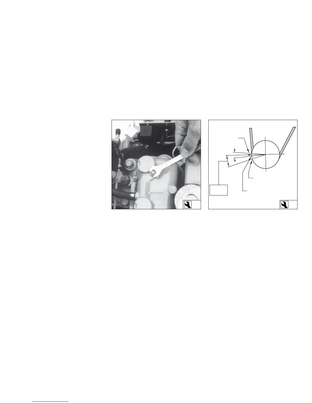
17°
Markering op
motorblok
Markering BDP
Markering
injectietijdstip
2°
2°
60
6 Maintenance
Checking valve clearance
Every 500 operating hours.
34 Checking / adjusting valve clearance
Checking the valve clearance must be done
with a cold engine, that is an engine which
did not run for at least 6 hours.
35 Remove rocker cover
• Remove the 2 nuts of the rocker cover.
• Complete the following steps:
36 Locating TDC
• Locate the Top Dead Center (TDC), at the
end of the compression stroke, for cylinder
1 by barring the engine slowly until the TDC
marks of the engine block and the crank
pulley match.
Note: There are two TDC’s e.g. compression
and suction. At the TDC at the end of the compression stroke the rocker arm does not move
when the crank pulley is rotated a little.
10 27
VD01040
VD01049

61
6 Maintenance
Checking valve clearance
Every 500 operating hours.
37 Adjusting valve clearance
Cylinders are numbered consecutively, beginning at the front end.
• Check valve clearance at cylinder 1 and adjust if necessary.
• Rotate the crankshaft 180° clockwise and
check valve clearance at cylinder 2.
10
VD01016
VD00922
ValVe ClearanCe: inlet
0.25 mm (0.010”)
exhaust
0.25 mm (0.010”)

62
6 Maintenance
Checking the V-belt
Every 500 operating hours.
38 Inspection V-belt
• Inspect the belt for wear and tear (fraying
and cracking). Belts which are in poor condition should be replaced.
39 Checking tension
• Check tension of the V-belt by applying
moderate nger and thumb pressure. If the
deection of the belt is more than 12 mm
(1/2”), using about 10 kg (20 lbs) thumb
pressure, it should be tensioned.
40 Tensioning V-belt
• Loosen the bolt of the adjustment bracket
and both the alternator mounting bolts.
Now push the alternator outwards until the
belt tension is correct.
• Now rst re-tighten the upper mounting
bolt of the alternator.
• Then re-tighten the bolt of the adjustment
bracket and the lower mounting bolt.
1412
VD00128
VD00034
VD00129
Danger
Check, tension and change belts only with the
engine o. Ret belt guard, if provided.
V-belt, art.Code:
STM7369

63
6 Maintenance
Flexible engine mounts, hose connections and fasteners
Every 500 operating hours.
41 Check exible engine mounts
• Check the bolts which secure the damper
element, the mounting bolts to engine bed
and the nuts at the adjustment spindle for
tightness.
• Inspect the rubber element of the engine
support for cracks. Also check the deection of the damper element, the deection
inuences the alignment of engine and
propshaft! Re-align engine in case of doubt.
• Inspect all hose connections of the coolingsystem. (Cracked hoses, loose hose clamps)
43 Check fasteners
• Check tightness of all fasteners, bolts and
nuts.
42 Inspection hose connections
VD01046
VD00928

64
6 Maintenance
Raw water pump inspection
Every 1000 operating hours.
44 Raw water pump inspection
The rubber impeller of the outboard water
pump is not proof against running dry. If the
water supply has been blocked, it may be necessary to replace the impeller. Always carry a
spare impeller on board.
45 Pump cover removal
Inspection where appropriate changing is as
follows:
• Close the sea cock.
• Remove the cover of the pump by unscrew-
ing the screws out of the housing.
46 Impeller removal
• Slide the impeller o of the shaft using a
waterpump plier.
• Mark the impeller to ensure correct re-installation if it is to be re-used. The impeller
must be installed in the same position as
removed.
10
VD01125
VD01126 / VD01031
note
Only engines with intercooling!

65
6 Maintenance
Raw water pump inspection
Every 1000 operating hours.
47 Impeller inspection
• Inspect the impeller for damage.
• Replace the impeller if necessary.
48 Re-install the impeller
• The impeller should be lubricated with
glycerin or a non-petroleum based lubricant such as a silicone spray before tting it
into the impeller housing.
• Fit the impeller to the pump shaft. (if an
existing impeller is re-used, install it in the
same position as removed).
49 Reinstall the pump cover
• Reinstall the cover with a new O-ring.
• Check the water lter and open the sea
cock.
VD00004
VD00127
VD00927
impeller + o-ring, art.Code
: STM7691
o-ring, art.Code
: STM7696

66
6 Maintenance
Coolant replacement
Every 1000 operating hours.
50 Coolant replacement
The coolant has to be replaced every 1000 operating hours or at least once every two years.
N.B. Replacing the coolant may also be necessary as part of the winter storage procedure;
in case that the coolant present in the cooling
system oers insucient protection for the
winter.
Danger
Be aware of the risk of skin burning during
draining the hot coolant! Used coolant must
be collected in a container for proper disposal
according to laws and regulations.
Warning
Cooling system protective
liquids must be disposed
of in accordance with environmental regulations.

67
6 Maintenance
Coolant replacement
Every 1000 operating hours.
51 Draining of coolant
• Remove the drain plugs from the engine
block (1) and heat exchanger (2).
• Remove the ller cap to vent the cooling
system and check that all the coolant has
been drained.
• After draining replace the drain plugs.
note
Keel cooler
How the cooling system in engines with
keel cooling should be drained depends
on the installation of the keel cooler.
Refer to the keel cooler manufacturer’s instructions for this.
Check using a coolant hydrometer whether the coolant is providing sucient protection against freezing if total draining o
is not possible.
14 13
1
2
VD01018
VD01025

68
6 Maintenance
Coolant replacement
Every 1000 operating hours.
52 Filling the cooling system
• Remove the cap of the ller neck on the top
of the heat exchanger housing.
• Remove the bolt from the upper side of the
thermostat cover, so that air can escape
from the cooling system.
• Fill the cooling system.
Use a mixture of 40% antifreeze (ethyleneglycol based) and 60% tap water or use a special coolant.
For specications see page 109.
Caution
Never ll the cooling system with sea water or
brackish water.
Water heater
If a water heater is connected to the engine and this heater is positioned above
the upper side of the engine than bleeding
of the heater will not take place automatically! Fill the heater separately to bleed the
cooling system completely.
Coolant quantitiy:
2.2 litres
(3.8 Imp. pt, 4.6 US pt)
17
VD01005
VD01004
note
For a keel-cooled version, see page 19.
If a water heater is connected, see page 20
and 21

1 cm
(3/8”)
COOLANT
69
6 Maintenance
Coolant replacement
Every 1000 operating hours.
The level of the coolant must be approx. 1 cm
(
3
/8”) below the lower edge of the ller neck.
Bleeding will take place automatically during
lling!
• After lling replace the ller cap and reinstall the plug.
• After the engine has run for the rst time
and has reached operating temperature
and has cooled down again to ambient
temperature, check the coolant level in the
heat exchanger housing.
• If necessary, add coolant.
Caution
Never ll the cooling system with sea water or
brackish water.
VD00158

70
6 Maintenance
Checking the starter motor and alternator
Every 1000 operating hours.
53 Checking the starter motor
• Check for visible defects.
• Check whether the Bendix engages with
the starter ring when the starter motor is
activated. If the Bendix does not engage
properly, contact your Vetus dealer.
54 Checking the alternator
• Check for visible defects.
• Remove the alternator belt. Turn the pulley
by hand to check whether the alternator
can be turned easily. If this is not the case,
contact your Vetus dealer.
VD01252
VD01251

Lead seal
Maximum speed
adjustment screw
Minimum speed
adjustment screw
71
6 Maintenance
Checking engine speed
At full load (with the boat cruising) the maximum engine speed should be about 3,000
resp. 3600 RPM (see technical data page 101).
If the engine does not reach this speed, it is
being overloaded!
If this is the case, check the ship’s propeller for
defects or irregularities, and also to see that it
is the correct pitch and diameter.
56 Adjusting engine idling speed
If the engine speed diers from that stated
above, it must be adjusted.
The engine idling speed can be reset using
the adjustment screw on the fuel pump.
55 Checking engine speed
The engine idling speed should be 850 rpm.
• Allow the engine to warm up normally (until the coolant temperature reaches at least
60°C (140°F).) before checking and/or adjusting the idling speed.
• Check the engine RPM using a rev. counter,
or use the rev. counter tted to the control
panel.
Warning
The maximum engine speed adjustment screw has been correctly set at
the factory and sealed. DO NOT attempt to remove this seal.
10
VD00134
VD00931

72
6 Maintenance
Cleaning the heat exchanger
note
Cleaning of the heat exchanger is not a
routine maintenance job.
Only clean the heat exchanger if this is
(badly) fouled.
Under normal conditions of use cleaning the
heat exchanger is not necessary!
The engine temperature will be higher than
normal if the heat exchanger is fouled.
Possible causes of fouling are:
- Small rubber particles from a damaged sea
water pump impeller.
- Growth of algae or seaweed.
note
Only engines with intercooling!

73
6 Maintenance
Cleaning the heat exchanger
57 Remove the drain plug
• Close the seacock and detach the water inlet hose from the sea water pump.
• Drain the coolant: To do this, remove the
drain plug from the heat exchanger housing.
• Remove the ller cap from the top of the
heat exchanger housing to allow air into
the system and check that all coolant has
drained o.
58 Removal of bolts out of the end covers
• Take out both central bolts from the end
covers and take the end covers with the Orings out of the housing.
note
Only engines with intercooling!
13
5
VD01003
VD01018
VD01019

74
6 Maintenance
Cleaning the heat exchanger
59 Remove heat exchanger
• Slide the heat exchanger out of the housing.
60 Cleaning the heat exchanger
• Clean the heat exchanger: Use a pipe cleaner to remove fouling in the pipes.
• Then rinse the heat exchanger pipes with
clean water.
• Ensure that both heat exchanger end
chambers are free from dirt.
note
Only engines with intercooling!
6
VD01021
VD01020
STM7217

75
6 Maintenance
Cleaning the heat exchanger
61 Replacing heat exchanger
• Replace the heat exchanger in the original
position in the heat exchanger housing.
• Use new O-rings (61 x 2.5 mm) which have
been greased.
• Ret the drain plug.
• Reconnect all hoses previously removed.
• Rell the cooling system, see page 68.
note
Only engines with intercooling!
o-ring, art.Code:
STM6113 (2 x)
62 Replacing the end covers
• Fit the end covers in the housing.
• Tighten up the bolts when both covers are
in the correct position.
STM6202
VD00157

76
7 Winter storage procedure
Make sure that the engine compartment is
well ventilated during the winter period.
Good ventilation prevents damp in the engine compartment, thus preventing corrosion
of the engine from occurring.
The engine should be inspected at the end of
the sailing season and any necessary repairs
carried out.
Consult a Vetus Dealer if help is required with
this.
Inspections and maintenance work to be carried out are:

77
7 Winter storage procedure
Inspections and maintenance work to be carried out: page
1 Clean the engine, remove any salt. Paint any rust spots and spray the whole engine with a protective
medium, for example CRC protective 6-66.
78
2 Drain o the water from the fuel system and ll the fuel tank. 78
3 Make sure that the engine fuel system is lled with a fuel mixture with protective properties. 79
4 Flush out the raw water circuit with fresh water and if necessary ll with antifreeze. Clean the heat
exchanger if necessary.
80
5 Make sure that the cooling system is lled with a suitable anti-freeze. 81
6 Change the oil lter and the engine oil. 82
7 Change the oil in the gearbox. 82
8 Disconnect the battery cables, charge the batteries if necessary and grease the battery terminals. 83

78
7 Winter storage procedure
1 Corrosion protection
The various parts of the engine (except the
engine block) have been treated with an
anti-corrosion protective medium. In order
to prevent corrosion, the engine should be
rinsed o to remove any salt residues. If there
is any corrosion, the paint should be touched
up. Engine parts that become hot must be
touched up with heat-resistant paint.
2 Fuel system
• Drain the water from the water separator/
fuel lter and the fuel tank.
Ensure that the tank is completely lled with
fuel.
• Install a new fuel lter. (page 55).
VD00803
VD00133

79
7 Winter storage procedure
3 Protective fuel mixture
• Connect the fuel supply pipe to a can lled
with protective diesel fuel, for example ‘Calibration Fluid’ (ISO 4113) or with a mixture
of 1 part of engine oil
[1]
to 9 parts of clean
fuel
[2]
.
• Use this mixture to run the engine at no
load for approx. 5 minutes.
• Stop the engine.
[2]
Only use CEN EN 590 Diesel fuel.
Preferably water-free fuel.
Collect some fuel from the return pipe,
while engine is running.
VD00136
tip!
Combine running the engine with the
protective fuel mixture with ushing
the raw water circuit with fresh water,
see ‘Winter storage procedure - Raw
water cooling system’.
Caution
Never run the engine under load with
this mixture of fuel and oil.
VD
[1]
Engine oil with protective properties.
E.g.:
- Vetus Marine Diesel Engine Oil 15W40
- Shell Rimula R4 L 15W40

80
7 Winter storage procedure
4 Raw water cooling system
• Close the sea cock.
• Remove the lid of the water strainer.
• If necessary, clean the raw water strainer.
• Connect the raw water intake to a fresh wa-
ter (tap water) supply or a tank containing
fresh water. Open the tap and allow the engine to idle for at least 5 minutes to remove
any salt and contamination from the raw
water cooling system.
Make sure that there is a sucient supply
of water to prevent the engine from overheating.
• Stop the engine and close the sea cock.
• The raw water system must be protected in
areas where the temperature drops to below zero during the winter.
Pour 1 litre (1/4 gallon) of anti-freeze (preferably a non-toxic biodegradable anti-freeze)
into the water strainer and run the engine
until the anti-freeze has disappeared into
the cooling system.
tip!
Combine ushing the raw water circuit
with fresh water with running the engine with the protective fuel mixture,
see ‘Winter storage procedure - Protective fuel mixture’
Heat exchanger
Only clean the heat exchanger if this is
absolutely necessary, see page 72.
Raw water pump
Check the impeller of the raw water
pump at least once every two years, see
page 64.
VD00125
VD00801
note
Only engines with intercooling!

81
7 Winter storage procedure
Anti-freeze can be toxic. Take care that no
anti-freeze is spilled into the waterway
• Check the seal between the lid and housing after cleaning and re-assembling the
strainer.
An improperly sealed lid will result in air
sucked in by the raw water pump which again
will result in overheating of the engine
5 Fresh water cooling system
To avoid corrosion during winter storage the
cooling system must be lled with an antifreeze/water mixture (or a coolant).
For specications see page 109.
N.B. Replacing the coolant is only necessary if
the coolant present in the cooling system offers insucient protection for the winter.
For coolant replacement see page 66.
VD01003
tip!
Protect the sea cock as follows:
With the motor stopped.
• Place the sea cock in a position that it
is just opening.
• Pour a small amount of non-toxic biodegradable anti-freeze into the raw
water strainer.
• Close the sea cock as soon as it is
lled with anti-freeze.

82
7 Winter storage procedure
6 Lubrication system
With the engine still at operating temperature: (If not, run the engine until warm, then
turn o.)
• Replace the oil lter and change the engine
oil; use oil with protective properties. See
page 47.
For quantity and oil specication see page
102 and 106.
7 Changing the gearbox oil
• Stop the engine and change the oil of the
gearbox. (page 58 and 59)
VD01026
VD01010
VD01034

83
7 Winter storage procedure
8 Electrical system
• Disconnect the battery cables. • Charge batteries during winter lay-up regularly if required!
• Follow the recommendations given on
pages 50 to 53 or consult the recommendations given by the battery supplier for inspection and maintenance of the batteries.
CT40063
VD00139

84
8 Recommissioning after winter storage
The engine must be inspected and any maintenance work carried out at the beginning of
the sailing season.
Consult a Vetus Dealer if help is required with
this.
Inspections and maintenance work to be carried out are:
Inspections and maintenance work to be carried out are: page
1 Drain the water from the fuel system. 85
2 Check the raw water system. 86
3 Check the coolant level in the internal cooling system. 87
4 Check the oil level. 87
5 Check the batteries and reconnect these. 88
6 Check the operation of the engine. 88
7 Check all hose connections for leaks. 89
8 Check the operation of the instruments and the engine controls. 89

85
8 Recommissioning after winter storage
1 Fuel system
• Drain the water from the water separator/
fuel lter. (page 44)
• Drain the water from the fuel tank. • Open the fuel valve.
VD00141
VD00803
VD00137

86
8 Recommissioning after winter storage
2 Raw water cooling system
• Check that the lid of the raw water strainer
is reinstalled.
• Check whether the lid of the raw water
pump and drain plugs are reinstalled. (pages 64, 67)
• Re-tighten possible loose hose clamps.
10
VD01125
VD00801
VD01045
note
Only engines with intercooling!

OIL
COOLANT
87
8 Recommissioning after winter storage
• Open the sea cock.
3 Fresh water cooling system
• Check the coolant level. (page 42)
4 Lubrication system
• Check the engine oil level. (page 40)
VD01003
VD00138
VD01001

88
8 Recommissioning after winter storage
5 Electrical system
• Make sure that the batteries are fully
charged. (page 50, 83)
• Connect the batteries.
6 Switching on
• Turn the start key on the instrument panel
clock-wise; the warning lights for oil pressure and alternator will now light up and
the alarm buzzer will sound.
VD00140
CT40063
VD00107

89
8 Recommissioning after winter storage
7 Check engine for leaks
• Start the engine.
• Check the fuel system, the cooling system
and the exhaust for leakage.
8 Checking instruments and remote con-
trols
• Check the operation of the instruments, the
remote control and the gearbox.
VD00581
VD01046

90
9 Troubleshooting
General
Engine faults are in most cases caused by improper operation or insucient maintenance.
In case of a fault, always check rst that the
operation and maintenance instructions have
been followed.
In the following tables information is given
about the possible causes of faults and suggested remedies. Please note that these tables can never be complete.
If you are unable to identify the cause of the
fault or to rectify it yourself, then contact the
nearest service representative.
Danger
Before starting, make sure that nobody is in
the immediate vincinity of the engine.
When carrying out repair, never start the engine with the fuel injection pump removed
removed.
Disconnect battery!

91
9 Troubleshooting
Fault nding table
Fault page
1 Engine will not crank 92
2 Engine cranks but will not start, no smoke from exhaust 92
3 Engine cranks but will not start, smoke from exhaust 93
4 Engine starts but runs unevenly (rough idling) or stalls 93
5 Engine does not reach maximum rpm under load 94
6 Engine overheats 95
7 Engine not ring on all cylinders 95
8 Engine has little or no oil pressure 96
9 Engine oil consumption excessive 96
10 Fuel consumption excessive 97
11 Black exhaust smoke (idling) 97
12 Blue exhaust smoke (idling) 97
13 Black exhaust smoke (at load) 98
14 White exhaust smoke (at full load) 98
15 Burnt oil trace in exhaust line . 99

92
1 Engine will not crank
Possible fault Remedy
Faulty or discharged battery (too
low voltage ) .
Check / recharge battery and
check engine alternator and/or
battery charger.
Fuse blown. Replace.
Loose or corroded connections
in starting circuit.
Clean and tighten connections.
Wrong engine electric mass connection.
Repair.
Starter relay is not engaged due
to a voltage too low; caused by
a very long intermediate cable
from engine to control panel.
Install an auxiliary starter relay
Faulty starter-switch or faulty
starter-relay.
Check / replace.
Faulty starter-motor or pinion
does not engage.
Check / replace starter-motor.
Seized components. Repair.
Control lever not in neutral. Put operating lever in neutral.
Water in the cylinder . Check / Repair.
2 Engine cranks but will not start, no smoke from exhaust
Possible fault Remedy
(Nearly) Empty fuel tank. Rell.
Fuel stop valve closed. Open.
Fuel pre-lter clogged . Clean /replace
Fuel lter clogged with water
and/or contamination.
Check or replace.
Vent line of fuel supply tank
clogged.
Check / clean.
Faulty injector/injection pump.. Check, replace if required.
Leaking fuel supply line or fuel
injection line.
Check / replace.
Air in fuel system. Check and bleed.
Exhaust restricted. Check.
9 Troubleshooting
Fault nding table

93
9 Troubleshooting
Fault nding table
3 Engine cranks but will not start, smoke from exhaust
Possible fault Remedy
Faulty injector/injection pump. Check, replace if required.
Air in fuel system. Check and bleed.
Wrong fuel quality or contaminated fuel.
Check fuel. Drain and ush fuel
tank. Replace with new fuel.
Incorrect injection timing. Check / adjust.
Setting of stop valve incorrect. Check / adjust.
Incorrect lube oil SAE class or
quality for ambient temperature.
Replace.
Faulty glow plugs. Check / replace.
Insucient intake air. Check.
Incorrect valve clearance. Adjust.
4 Engine starts but runs unevenly (rough idling) or stalls
Possible fault Remedy
(Nearly) Empty fuel tank. Rell.
Fuel supply line restricted. Check / clean.
Fuel lter clogged with water
and/or contamination.
Check or replace.
Vent line of fuel supply tank
clogged.
Check / clean.
Faulty injector/injection pump. Check, replace if required.
Leaking fuel supply line or fuel
injection line.
Check / replace.
Air in fuel system. Check and bleed.
Wrong fuel quality or contaminated fuel.
Check fuel. Drain and ush fuel
tank. Replace with new fuel.
Exhaust restricted. Check.
Incorrect valve clearance. Adjust.
Idle setting too low. Check/ adjust.

94
9 Troubleshooting
Fault nding table
5 Engine does not reach maximum rpm under load
Possible fault Remedy
Fuel pre lter clogged . Clean/replace.
Fuel lter clogged with water
and/or contamination.
Check or replace.
Faulty injector/injection pump. Check, replace if required.
Leaking fuel supply line or fuel
injection line.
Check / replace.
Air in fuel system. Check and bleed.
Wrong fuel quality or contaminated fuel.
Check fuel. Drain and ush fuel
tank. Replace with new fuel.
Incorrect injection timing. Check / adjust.
Setting of stop valve incorrect. Check / adjust.
Oil level too high. Lower level.
Lubricating oil incorrect SAE
spec or quality for ambient
temperature.
Replace.
Insucient intake air. Check.
Exhaust restricted. Check / clean.
Incorrect valve clearance. Adjust.
Transmission defect. Check
Engine overloaded. Check size of propeller. Clean the
propeller.
Boat load inadequate . -
5 Engine does not reach maximum rpm under load
Possible fault Remedy
Hull/propeller dirty . Clean

95
9 Troubleshooting
Fault nding table
6 Engine overheats
Possible fault Remedy
Faulty injector/injection pump. Check, replace if required.
Sea cock closed. Open.
Raw water strainer clogged. Check / clean.
Faulty raw water pump impeller. Check / replace.
Leak in raw water feed system. Check / replace.
Coolant level too low. Check / top up.
Faulty coolant pump. Check / replace.
Faulty thermostat. Check / replace.
Leak in coolant circuit . Check.
Heat exchanger dirty or clogged
as a result of rubber particles
from a worn impeller.
Check / clean.
Oil level too low. Increase level.
Oil level too high. Lower level.
Faulty oil lter. Replace.
Insucient intake air. Check / replace air intake lter.
Motor becomes apparently
overheated as a result of faulty
temperature switch, sensor or
meter.
Check / replace.
7 Engine not ring on all cylinders
Possible fault Remedy
Fuel supply line restricted. Check / clean.
Fuel lter clogged with water
and/or contamination.
Check or replace.
Faulty injector/injection pump. Check, replace if required.
Leaking fuel supply line or fuel
injection line.
Check / replace.
Air in fuel system. Check and bleed.
Faulty glow plugs. Check / replace.
Incorrect valve clearance. Adjust.

96
9 Troubleshooting
Fault nding table
8 Engine has little or no oil pressure
Possible fault Remedy
Oil level too low. Increase level.
Incorrect lube oil SAE class or
quality for ambient temperature.
Replace.
Blocked oil lter. Replace.
Faulty oil pump. Repair / replace.
Oil leaks . Check.
Excessive inclination of engine. Check / Adjust.
Oil pressure apparently too low
due to faulty oil pressure switch,
sensor or meter.
Check / replace.
9 Engine oil consumption excessive
Possible fault Remedy
Oil level too high. Lower level.
Incorrect lube oil SAE class or
quality for ambient temperature.
Replace.
Leak in lubricating oil system. Repair / replace.
Insucient intake air. Check.
Excessive wear of cylinder/piston.
Check compression; overhaul
engine.
Engine overloaded. Check size of propeller. Clean the
propeller.
Excessive inclination of engine. Check / Adjust.

97
9 Troubleshooting
Fault nding table
10 Fuel consumption excessive
Possible fault Remedy
Faulty injector/injector pump. Check, replace if necessary.
Incorrect fuel quality or dirty
fuel.
Check fuel. Drain and rinse fuel
tank. Replace with new fuel.
Fuel leaks . Check and repair.
Incorrect injection timing. Check / adjust.
Insucient air intake. Check.
Excessive wear of cylinder /
piston.
Check compression; refurbish
engine.
11 Black exhaust smoke (idling)
Possible fault Remedy
Injector fault Check /replace.
Oil level too high. Lower level.
Excessive inclination of engine. Check / Adjust.
12 Blue exhaust smoke (idling)
Possible fault Remedy
Oil level too high. Lower level.

98
9 Troubleshooting
Fault nding table
13 Black exhaust smoke (at load)
Possible fault Remedy
Faulty injector / injection pump. Check / replace if required.
Incorrect injection timing. Check / adjust.
Oil level incorrect. Check .
Insucient intake air, air lter
dirty.
Check/clean the lter .
Incorrect valve clearance. Adjust.
Excessive wear of cylinder /
piston.
Check compression; refurbish
engine.
Engine overloaded, max. rpm is
not reached.
Check sizes of propeller.
Engine overloaded, dirty propeller -boat hull, excessive load
on-board.
Check /clean.
14 White exhaust smoke (at full load)
Possible fault Remedy
Faulty injector/injection pump. Check, replace if required.
Air in fuel system. Check and bleed.
Wrong fuel quality or contaminated fuel.
Check fuel. Drain and ush fuel
tank. Replace with new fuel.
Water in fuel system. Check water separator.
Incorrect injection timing. Check / adjust.
Faulty glow plugs. Check / replace.
Incorrect valve clearance. Adjust.
Vapour in exhaust gases condenses as a result of very low
ambient temperature.
-
 Loading...