

Page 1
FOKKERSTRAAT 571 - 3125 BD SCHIEDAM - HOLLAND - TEL.: +31 10 4377700 - TELEX: 23470
TELEFAX: +31 10 4372673 - 4621286 - E-MAIL: [email protected] - INTERNET: http://www.vetus.com
Flexibele motoropstelling
Voor zowel de voorzijde als de achterzijde van de motor geldt dat
de indrukking van de trillingdempers links en rechts gelijk dient te
zijn. Tussen voor- en achterzijde is een verschil in indrukking toegestaan en veelal onvermijdelijk.
Een juiste instelling van de trillingdempers kan als volgt worden
gerealiseerd:
- Stel de motor ongeveer in lijn met de schroefas, met behulp van
de stelmoeren op de trillingdempers, de schroefas nog
NIET
verbinden met de flens van de keerkoppeling.
- Licht de motor aan de voorzijde juist zoveel op dat de beide
voorsteunen los komen van de moeren van de trillingdempers.
- Laat de motor zakken en verstel de moeren zodanig dat beide
motorsteunen gelijktijdig op de moeren komen te rusten.
- Herhaal dit voor de achterzijde van de motor.
Na het juist instellen van de trillingdempers kan het uitlijnen van de
motor worden uitgevoerd door voor of achter beide stelmoeren,
zowel links als rechts,
exact evenveel slagen te verdraaien.
In langsrichting moeten de trillingdempers spanningsvrij gemonteerd kunnen worden. Vervormde trillingdempers kunnen trillingen
en geluid aan het schip overdragen.
De sleufgaten in de trillingdempervoeten geven de mogelijkheid de
opstelling zijdelings te corrigeren.
Controleer de uitlijning nogmaals als de boot in het water ligt.
Voor een correcte flexibele opstelling van de scheepsmotor dient
aan de volgende eisen te worden voldaan:
- het rubber van de motorsteunen moet ten gevolge van de statische belasting* tenminste de aangegeven
minimale hoeveel-
heid worden ingedrukt.
- het rubber van de motorsteunen mag ten gevolge van de som
van de statische én dynamische belasting* niet meer dan de
aangegeven
maximale hoeveelheid worden ingedrukt.
Zie tabel en grafiek.
* Statische belasting: de belasting veroorzaakt door het eigen gewicht
van de motor.
Dynamische belasting: de belasting veroozaakt door het koppel van de
motor.
030103.04 05-05 Printed in the Netherlands
K25
K40
LMX140
LMX210
LMX340
LMX500
MITSTEUN
Copyright © 2005 Vetus den Ouden n.v. Schiedam Holland
HY
K
LMX
Mitsteun
030103.04
Flexibele motorsteunen
NEDERLANDS ENGLISH
030103.04
030103.04
Flexible engine mountings
Hoofdafmetingen
Principal dimensions
Hauptabmessungen
Dimensions principales
Dimensiones principales
Dimensioni principali
Flexible engine mounting assembly
It is important that an equal load is applied to the left and the right
flexible mounting at the front section of the engine; and the same
goes for the engine’s rear section: equal load to the left and the
right support. It is admissible - and often unavoidable - that a different load is applied to the front and rear flexible engine mountings.
A proper adjustment of the engine supports can be assured by the
following procedure:
- Provide for an approximate alignment of engine and shaft
assembly, by means of the nuts on the support spindle, but do
NOT connect the propeller shaft yet to the gearbox flange.
- Lift the front part of the engine slightly, up to the point that both
front engine feet become free of the lower nuts of the flexible
supports.
- Lower the engine, while adjusting the nuts in such a way that
both engine feet touch the nuts simultaneously.
- Repeat the foregoing with the rear section of the engine.
After the proper adjustment of the flexible engine supports, the precise alignment can be obtained by turning the nuts of the rear and
front supports, both left and right, by
exactly the same number of
turns.
It is imperative that the flexible engine mountings will be installed
free of pre-torsion alongships, as this would transmit vibrations and
noise to the boat.
The slot in the baseplate of the flexible supports allow for installation corrections sideways.
Verify the proper alignment anew, when the boat has been
launched.
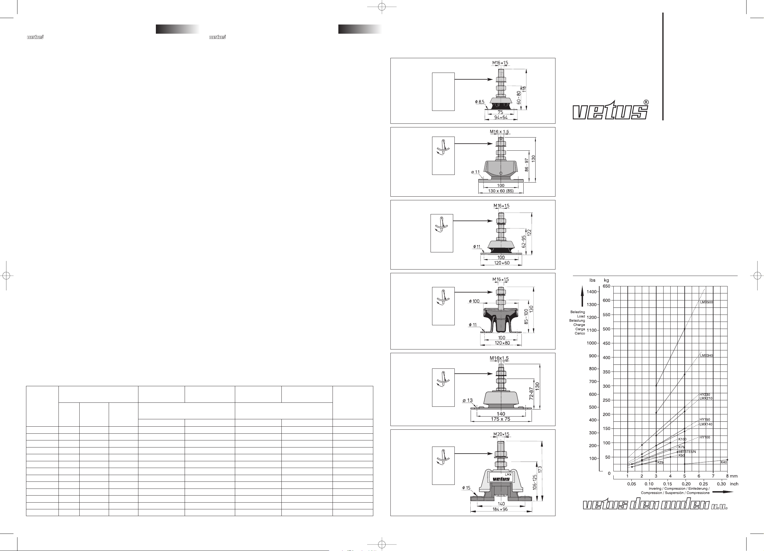
For a proper flexible mounting assembly of the ship engine, the following criteria must be satisfied:
- the rubber engine mountings should be at least pushed in a
minimum amount as a result of the static load *, and
- the rubber engine mountings should be pushed in no more than
the
maximum amount as a result of the sum of the static and
dynamic load *.
See table and diagram.
* Static load: the load caused by the weight of the engine itself.
Dynamic load: the load caused by the torque of the engine.
Flexibele motorsteunen
Flexible engine mountings
Flexible Motorlager
Supports-moteurs flexibles
Soportes motor flexibles
Supporti motore flessibili
Installatieinstructies
Installation instructions
Installationsanleitung
Instructions d’installation
Instrucciones de instalación
Istruzioni per l’installazione
NEDERLANDS
ENGLISH
DEUTSCH
FRANÇAIS
ESPAÑOL
ITALIANO
HY100
HY150
HY230
Type
Stijfheidsverhouding
Stiffness ratio
Min. belasting
Min. load
Min. invering
Min. compression
Max. belasting
Max. load
Max. invering
Max. compression
Hardheid
Hardness
verticaal
vertical
dwarsscheeps
athwartships
langsscheeps
fore and aft
statisch
static
statisch + dynamisch
static + dynamic
[kg] [mm] [kg] [mm] [˚ Shore]
K25 1 1,4 1,4 15 1,3 35 3 45
K40 1 1 2,4 25 5 40 8 50
K50 1 0,75 2,5 25 2 50 4 45
K75 1 0,75 2,5 38 2 75 4 55
K100 1 0,75 2,5 50 2 100 4 65
Mitsteun 1 1 1 25 1,3 67 4,5 45
HY100 1 1,2 3,5 40 2 100 5 40
HY150 1 1,2 3,5 60 2 150 5 50
HY230 1 1,2 3,5 92 2 230 5 60
LMX140 1 1 7 85 3 140 5 35
LMX210 1 1 7 125 3 210 5 45
LMX340 1 1 7 205 3 340 5 55
LMX500 1 1 7 300 3 500 5 65
K50
K75
K100
21 kgm
152 ft.lbs.
205 Nm
21 kgm
152 ft.lbs.
205 Nm
21 kgm
152 ft.lbs.
205 Nm
21 kgm
152 ft.lbs.
205 Nm
21 kgm
152 ft.lbs.
205 Nm
42 kgm
304 ft.lbs.
412 Nm
030103.04 r01 05-05 10-05-2005 09:00 Pagina 1
Page 2
Flexible Motoraufhangung
Die Belastung der Motorstützen vorne und hinten soll jeweils links
und rechts gleich sein. Es ist akzeptabel - und öfters unvermeidlich
- daß die Eindruckung vorne und hinten unterschiedlich ist.
Die genaue Einstellung der Motorstützen kann folgendermaßen
durchgeführt werden:
- Versorgen Sie ein ungefähres Ausrichten der Schraubenwelle
zum Motor, mit hilfe der Überwurfmuttern auf den Gewindebolzen, aber befestigen Sie die Schraubenwelle noch
nicht zum
Wendegetriebeflansch.
- Heben Sie demnächst die Vorderseite der Maschine so weit auf,
daß
die beiden vorderen Füße gerade von den Muttern der
flexiblen Stützen frei kommen.
- Senken Sie jetzt die Maschine wieder ab, unter gleichzeitigem
Verdrehen der Muttern, so daß
die beiden Motorfüße sich zur
gleichen Zeit auf die Muttern setzen werden.
- Wiederholen Sie dieses Verfahren an der Rückseite des Motors.
Nach dem richtigen Einstellen der Schwingungsdämpfer, kann das
feine Auswuchten der Maschine geschehen durch drehen der
Mutter vorne, hinten rechts und links mit dem
gleichen Anzahl von
Schlägen.
In der Längsrichtung sollen die flexiblen Motorstützen
spannungsfrei montiert werden. Verzerrte Motorlagerungen
können dem Schiffe Vibrationen und Lärm übertragen. Die Schlitzlöcher der Motorstützenfüße erlauben eine seitliche Korrektur.
Prüfen Sie die Auflüchtung nochmal genau wenn das Schiff im
Wasser schimmt.
Für eine ordnungsgemäße flexible Aufhängung des Schiffsmotors
müssen folgende Voraussetzungen erfüllt werden:
- Der Gummi der Motoraufhängungen muß infolge der statischen
Belastung*
mindestens um das angegebene Mindestmaß
eingedrückt werden
- Der Gummi der Motoraufhängungen darf infolge der Summe
der statischen und dynamischen Belastung* um nicht mehr als
das angegebene
Höchstmaß eingedrückt werden.
Siehe Tabelle und Graphik.
* Statische Belastung ist die Belastung, verursacht durch das
Eigengewicht des Motors.
Dynamische Belastung ist die Belastung, hervorgerufen durch das
Drehmoment der Maschine.
Installation flexible
La charge des supports flexibles à gauche et à droit doit être la
même, aussi bien en avant qu’en arrière. Il est admissible - est souvent inévitable - qu’il y aura une différence de charge à l’avant et à
l’arrière du moteur.
L’installation propre des supports flexibles pourra être assurée en
faisant ce qui suit:
-A l’aide des écrous sur les fuseaux des supports flexibles, ali-
gner si bien que possible la ligne d’arbre au moteur, n’effectuant
pas encore la connexion actuelle.
- Lever l’avant du moteur jusqu’à ce que les pieds du moteur sont
précisément dégagés des écrous des supports flexibles.
- Faire baisser le moteur, en même temps tournant les écrous de
telle façon que les pieds avant du moteur toucheront les écrous
simultanément.
-Répéter cette procédure à l’arrière du moteur.
Ayant ajusté proprement les supports flexibles, l’alignement du
moteur pourra être assuré par tourner les écrous avant et arrière,
ainsi qu’à gauche et à droit, avec
exactement le même nombre de
coups.
En direction longitudinale, les supports flexibles sont à installer
sans torsion. Des supports tordus pourront transmettre des vibrations et du bruit au bateau.
Les trous ovalisés sur les socles des supports flexibles permettent
une correction latérale.
Vérifier de nouveau l’alignement propre quand le bateau est lancé
dans l’eau.
Pour un montage correct et flexible du moteur de bateau, il faut respecter les consignes suivantes:
- En raison de la charge statique*, le caoutchouc des supports de
moteur doit être enfoncé au moins jusqu’à la quantité
minimum
indiquée.
- Etant donné que la charge statique* et la charge dynamique*
s’additionnent, le caoutchouc des supports de moyeur ne doit
pas êrte enfoncé au-delà de la quantité
maximum indiquée.
Voir tableau et graphique.
* Charge statique est la charge causée par les poids du moteur propre.
Charge dynamique est la charge engendrée par le couple du moteur.
Grupo de montaje flexible del motor
Tanto para la parte delantera como trasera del motor, la compresión de los soportes amortiguadores de motor ha de ser igual a la
izquierda y a la derecha. Se admite (y a menudo resulta inevitable)
una diferencia de compresión entre la parte delantera y la trasera.
Un correcto ajuste de los soportes amortiguadores de motor se
realiza como sigue:
- Asegurar un alineación aproximada del motor y el eje propulsor,
por medio de las tuercas de ajuste en los soportes amortiguadores,
SIN conectar todavía el eje propulsor a la brida del
engranaje de inversión de marcha.
- Levantar un poco el motor en la parte delantera, de modo que
ambos soportes delanteros se liberen de las tuercas de los
soportes amortiguadores.
- Bajar el motor ajustando las tuercas de forma que ambos soportes amortiguadores se apoyen
simultáneamente en las tuer-
cas.
- Repetir este procedimiento para la parte posterior del motor.
Realizado el correcto ajuste de los soportes amortiguadores, se
puede proceder a la alineación del motor, girando en la parte
delantera o trasera, ambas tuercas de ajuste, tanto a la izquierda
como derecha,
exactamente el mismo número de vueltas.
Es imprescindible instalar los soportes amortiguadores libres de
pretensión en sentido lateral de la embarcación, ya que soportes
amortiguadores deformados pudieran transmitir vibraciones y
ruido a la embarcación.
Las ranuras existentes en los pies de los soportes amortiguadores
permiten corregir el montaje en sentido lateral.
Controlar nuevamente la alineación cuando la embarcación está
en el agua.
Para una instalación flexible correcta del motor de la embarcación,
es imprescindible observar las siguientes normas:
- La goma de los soportes motor - a causa de la carga estática*ha de presionarse al menos la cantidad
mínima indicada.
- La goma de los soportes motor - a causa de
la suma de la
carga estática y dinámica* - no se puede presionar más allá de
la cantidad máxima indicada.
Véanse la tabla y el gráfico.
* Carga estática: la carga causada por el propio peso del motor.
Carga dinámica: la carga causada por el par motor.
Installazione flessibile del motore
La compressione degli ammortizzatori, sinistro e destro, deve
essere uguale nella parte anteriore e posteriore del motore. Tra la
parte anteriore e quella posteriore è consentita una certa differenza di compressione, che è pressoché inevitabile.
Una giusta regolazione degli ammortizzatori può essere ottenuta
come segue:
- Con l’ausilio dei dadi di regolazione posti sugli ammortizzatori,
mettere il motore in linea con l’albero dell’elica,
SENZA colle-
garlo alla flangia del cambio direzionale.
- Sollevare il motore anteriormente in modo che entrambi i sostegni anteriori escano dai dadi degli ammortizzatori.
- Calare il motore e regolare i dadi in modo che entrambi i sostegni tocchino
contemporaneamente i dadi.
- Ripetere la procedura per la parte posteriore del motore.
Dopo avere regolato gli ammortizzatori, il motore può essere allineato avvitando o svitando di un
uguale numero di giri entrambi i
dadi, destro e sinistro, anteriori o posteriori.
In senso longitudinale gli ammortizzatori devono poter essere
montati senza sopportare alcun carico. Ammortizzatori deformati
possono trasmettere vibrazioni e rumori all’imbarcazione.
Le guide nei piedi degli ammortizzatori permettono di correggere
lateralmente la regolazione degli ammortizzatori stessi.
Controllare nuovamente l’allineamento quando l’imbarcazione è in
acqua.
Per una corretta installazione flessibile del motore marino, è necessario soddisfare i seguenti requisiti:
- A seguito del carico statico*, la gomma dei sostegni del motore
deve subire almeno la compressione
minima indicata.
- A seguito della somma del carico statico e dinamico*, la
gomma dei sostegni del motore non deve subire una compressione superiore a quella
massima indicata.
Vedi tabella e grafico.
* Carico statico: il carico dovuto al peso proprio del motore.
Carico dinamico: il carico dovuto all’accoppiamento del motore.
Flexible Motorlager Supports-moteurs flexibles Soportes motor flexibles Supporti motore flessibili
030103.04 030103.04 030103.04 030103.04
DEUTSCH FRANÇAIS ESPAÑOL ITALIANO
Typ
Type
Steifheitsverhältnis
Ratio de raideur
Min. Belastung
Charge minimale
Min. Einfederung
Compr. minimale
Max. Belastung
Charge maximale
Max. Einfederung
Compr. maximale
Harte
Dureté
vertikal
verticale
querschiffs
latérale
längsschiffs
longitudinal
Statisch
Statique
Statisch + dynamisch
Statique + dynamique
[kg] [mm] [kg] [mm] [˚ Shore]
K25 1 1,4 1,4 15 1,3 35 3 45
K40 1 1 2,4 25 5 40 8 50
K50 1 0,75 2,5 25 2 50 4 45
K75 1 0,75 2,5 38 2 75 4 55
K100 1 0,75 2,5 50 2 100 4 65
Mitsteun 1 1 1 25 1,3 67 4,5 45
HY100 1 1,2 3,5 40 2 100 5 40
HY150 1 1,2 3,5 60 2 150 5 50
HY230 1 1,2 3,5 92 2 230 5 60
LMX140 1 1 7 85 3 140 5 35
LMX210 1 1 7 125 3 210 5 45
LMX340 1 1 7 205 3 340 5 55
LMX500 1 1 7 300 3 500 5 65
Tipo
Relación de rigidez
Rapporto di durezza
Carga mín.
Carico minimo
Suspensión mín.
Compr. minima
Carga max.
Carico massimo
Suspensión max.
Compr. massimo
Dureza
Durezza
vertical
verticale
transversal
transversal-
mente
a la largo
all’imbarcazio-
ne
Estática
Statico
Estática + dinámica
Statico + dinamico
[kg] [mm] [kg] [mm] [˚ Shore]
K25 1 1,4 1,4 15 1,3 35 3 45
K40 1 1 2,4 25 5 40 8 50
K50 1 0,75 2,5 25 2 50 4 45
K75 1 0,75 2,5 38 2 75 4 55
K100 1 0,75 2,5 50 2 100 4 65
Mitsteun 1 1 1 25 1,3 67 4,5 45
HY100 1 1,2 3,5 40 2 100 5 40
HY150 1 1,2 3,5 60 2 150 5 50
HY230 1 1,2 3,5 92 2 230 5 60
LMX140 1 1 7 85 3 140 5 35
LMX210 1 1 7 125 3 210 5 45
LMX340 1 1 7 205 3 340 5 55
LMX500 1 1 7 300 3 500 5 65
030103.04 r01 05-05 10-05-2005 09:00 Pagina 2
 Loading...