

VETUS HTP42R Hydraulic Pump with Check Valve, Hydraulic Pump without Check Valve HTP20, Hydraulic Pump with Check Valve HTP20R, Hydraulic Pump with Check Valve HTP30R, Hydraulic Pumps without Check Valve HTP30 Manual
...
Stuurpompen
Steering pumps
Steuerpumpen
Pompe de commande
Bomba de dirección
Pompa di governo
Copyright © 2003, 2004 Vetus den Ouden n.v. Schiedam Holland
Installatieinstructies
Installation instructions
Installationsanweisungen
Instructions d’installation
Instrucciones de
instalación
Istruzioni per
l’installazione
HTP20
HTP30
HTP42
HTP20R
HTP30R
HTP42R
2 2.0114
Stuurpompen HTP20(R), HTP30(R), HTP42(R
Inleiding
Deze handleiding behoort bij de Vetus stuurpompen type HTP20(R), HTP30(R) en
HTP42(R).
Deze handleiding bevat aanvullingen op de handleiding die bij de cilinder wordt toegevoegd.(2.0105 I.H30-175, of 2.0113 I.OB300)
Opmerking:
De Vetus EHP type ‘R’ zijn reeds voorzien van een ingebouwde terugslagklep.
Montage
Stuurpomp
De vuldop en de aansluiting voor de vereffeningsleiding* dienen zich altijd aan de bovenzijde, op het hoogste punt, te bevinden.
*) Indien er meerdere stuurpompen in de installatie zijn opgenomen, dienen alle oliere-
servoirs met elkaar verbonden te worden door middel van een vereffeningsleiding.
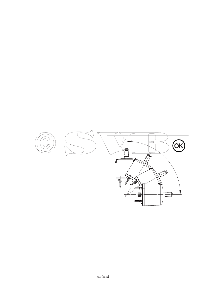
De pomp mag in elke stand, tussen horizontaal en verticaal, worden opgesteld.
Monteer de meegeleverde draadeinden met behulp van Loctite
®
in de stuurpomp.
De stuurpomp is standaard voorzien van een vuldop zonder beluchtingsgat. Indien noodzakelijk kan deze vervangen worden door de meegeleverde vuldop met beluchtingsgat.
Controleer bij een dubbele bediening of in de onderste stuurpomp een vuldop zonder gat
gemonteerd is.
90˚

2.0114 3
Stuurpompen HTP20(R), HTP30(R), HTP42(R
Olie expansietank
Indien een olie expansietank is geïnstalleerd, laat dan in alle stuurpompen de vuldop zonder beluchtingsgat zitten.
Aansluitingen
A, B Aansluiting cilinder
C Aansluiting vereffeningsleiding
Technische gegevens
Stuurpomp : HTP20(R) HTP30(R) HTP42(R)
Type : Axiaal plunjer pomp
Aantal plunjers : 5 5 7
Opbrengst : 19,7 cm
3
/omw. 30,0 cm3/omw. 42,0 cm3/omw.
Werkdruk : max. 40 bar (40 kg/cm2, 3923 kPa), bij ø 8 mm leidingdiameter
max. 56 bar (56 kg/cm2, 5492 kPa), bij ø 10 mm leidingdiameter
Aansluitingen : G 1/4 inwendige schroefdraad
Vuldop : G 3/8 inwendige schroefdraad
Gewicht,
zonder opgebouwde
terugslagklep : 3,3 kg 3,3 kg 3,3 kg
met opgebouwde
terugslagklep : 4,1 kg 4,1 kg 4,1 kg
Maximale
stuurdiameter : 38 cm 38 cm 53 cm
Overdrukventiel, alleen bij pompen met opgebouwde terugslagklep
Instelling : 60 bar (60 kg/cm
2
, 6000 kPa),
bij ø 8 mm leidingdiameter
70 bar (70 kg/cm
2
, 7000 kPa), bij ø 10 mm leidingdiameter
HTP HTPR
A
B
C
C
C
C
BA
NEDERLANDS

4 2.0114
Steering pumps HTP20(R), HTP30(R), HTP42(R)
Introduction
This manual relates to Vetus steering pumps, types HTP20(R), HTP30(R) and HTP42(R).
This manual is a supplement to the manual supplied with the cylinder. (2.0105 I.H30-175,
or 2.0113 I.OB300)
Note:
The Vetus EHP type ‘R’ is already equipped with a built-in check valve.
Fitting
Steering pump
The filler cap and balance tube* must always be on top of the unit, at the highest point.
*) When more than one pump is fitted, all oil reservoirs must be connected by balance
tubes.
The pump may be installed in any position
between horizontal and vertical.
Fit the threaded rod supplied into the steering pump using Loctite
®
.
The steering pump is supplied with a filler cap without air holes as standard. If necessary,
this can be replaced by the filler capwith air holes also supplied.
With double operation, check that the lowest steering pump is fitted with a filler cap with-
out a hole.
90˚

2.0114 5
Steering pumps HTP20(R), HTP30(R), HTP42(R)
Oil Expansion Tank
If an oil expansion tank is fitted, fit filler caps without air holes in all steering pumps.
Connections
A, B Cylinder
connections
C Balance tube
connection
Technical Data
Steering pump : HTP20(R) HTP30(R) HTP42(R)
Type : Axial plunger pump
Number of plungers : 5 5 7
Capacity : 19,7 cm
3
/rev. 30,0 cm3/rev. 42,0 cm3/rev.
(1.2 cu.inch/rev.) (1.8 cu.inch/rev.) (2.6 cu.inch/rev.)
Operating pressure : max. 40 bar (570 psi, 3923 kPa), at ø 8 mm tube diameter
max. 56 bar (797 psi, 5492 kPa), at ø 10 mm tube diameter
Connections : G 1/4 female thread
Filler cap : G 3/8 female thread
Weight,
without built-in
non-return valve : 3.3 kg (7.3 lbs) 3.3 kg (7.3 lbs) 3.3 kg (7.3 lbs)
with built-in
non-return valve : 4.1 kg (9.0 lbs) 4.1 kg (9.0 lbs) 4.1 kg (9.0 lbs)
Maximum wheel
diameter : 38 cm (1.5”) 38 cm (1.5”) 53 cm (2”)
Pressure relief valve, only by pumps with buit-in non-return valve
Setting : 60 bar (870 psi, 6000 kPa),
at ø 8 mm tube diameter
70 bar (1015 psi, 7000 kPa), at ø 10 mm tube diameter
HTP HTPR
A
B
C
C
C
C
BA
ENGLISH

6 2.0114
Steuerpumpen HTP20(R), HTP30(R), HTP42(R)
Einleitung
Diese Gebrauchsanleitung ist für die Vetus Steuerpumpen vom Typ HTP20(R), HTP30(R)
und HTP42(R) bestimmt.
Diese Gebrauchsanleitung enthält Ergänzungen zu der dem Zylinder beigefügten
Gebrauchsanleitung.
(2.0105 I.H30-175, oder 2.0113 I.OB300)
Bitte beachten:
Die Vetus EHP Typ ‘R’ ist bereits mit einem eingebauten Rückschlagventil ausgestattet.
Montage
Steuerpumpe
Der Einfüllstutzen und der Anschluß der Ausgleichsleitung* müssen immer oben, an der
höchsten Stelle, liegen.
*) Enthält die Anlage mehrere Pumpen, müssen alle Hydraulikölbehälter mit Hilfe einer
Ausgleichsleitung untereinander verbunden sein.
Die Pumpe darf in allen Positionen zwischen
horizontal und vertikal aufgestellt werden.
Die mitgelieferten Kabelenden mit Loctite
®
in der Steuerpumpe montieren.
Die Steuerpumpe ist standardmäßig mit einem Verschlussdeckel ohne Belüftungsloch
ausgestattet. Falls notwendig, kann dieser Verschlussdeckel durch einen mitgelieferten
Verschlussdeckel mit Belüftungsloch ausgetauscht werden.
Kontrollieren Sie bei einer doppelten Bedienung bitte, ob in die unterste Steuerpumpe ein
Verschlussdeckel ohne Loch eingesetzt worden ist.
90˚

2.0114 7
Steuerpumpen HTP20(R), HTP30(R), HTP42(R)
Ölausgleichsbehälter
Wenn ein Ölausgleichsbehälter installiert wurde, dann in allen Steuerpumpen den
Verschlussdeckel ohne Belüftungsloch sitzen lassen.
Anschlüsse
A,B Anschlüsse Zylinder
C Anschlüsse
Ausgleichsleitung
Technische Daten
Steuerpumpe : HTP20(R) HTP30(R) HTP42(R)
Typ : Axiale Kolbenpume
Plungerzahl : 5 5 7
Leistung : 19,7 cm
3
/Umdreh. 30,0 cm3/Umdreh. 42,0 cm3/Umdreh.
Betriebsdruck : max. 40 bar (40 kg/cm2, 3923 kPa), bei ø 8 mm Leitungsdurchmesser
max. 56 bar (56 kg/cm2, 5492 kPa), bei ø 10 mm Leitungsdurchmesser
Anschlüsse : G 1/4 Innengewinde
Einfüllstutzen : G 3/8 Innengewinde
Gewicht,
ohne Rückschlagventilaufsatz : 3,3 kg 3,3 kg 3,3 kg
mit Rückschlagventilaufsatz : 4,1 kg 4,1 kg 4,1 kg
Maximaler Steuerraddurchmesser : 38 cm 38 cm 53 cm
Überdruckventil, nur bei pumpen mit Rückschlagventilaufsatz
Einstellung : 60 bar (60 kg/cm
2
, 6000 kPa),
bei ø 8 mm Leitungsdurchmesser
70 bar (70 kg/cm
2
, 7000 kPa), bei ø 10 mm Leitungsdurchmesser
HTP HTPR
A
B
C
C
C
C
BA
DEUTSCH

8 2.0114
Pompe de commande HTP20(R), HTP30(R), HTP42(R)
Introduction
Ce manuel se rapporte aux pompes de commande Vetus de types HTP20(R), HTP30(R) et
HTP42(R).
Ce manuel contient des suppléments au manuel joint au cylindre.
(2.0105 I.H30-175, ou 2.0113 I.OB300)
N.B.
La EHP type ‘R’ est déjà équipée d’une soupape de retenue (double) incorporée.
Montage
Pompe de commande
Le bouchon de remplissage et le raccordement pour la ligne de compensation* devront
toujours se trouver au point le plus haut sur la partie supérieure.
*) Si plusieurs pompes de commande sont intégrées dans l’installation, tous les réservoirs
d’huile devront être reliés entre eux au moyen d’une ligne de compensation.
La pompe peut être placée dans toutes les
positions entre l’horizontale et la verticale.
Monter les embouts filetés fournis dans la pompe de commande à l’aide de Loctite
®
.
La pompe de commande est équipée en standard d’un bouchon de remplissage sans trou
d’aération. Celui-ci peut, si nécessaire, être remplacé par un bouchon avec un trou d’aération.
Dans le cas d’une double commande, contrôler si la pompe inférieure est dotée d’un bouchon sans orifice.
90˚

2.0114 9
Pompe de commande HTP20(R), HTP30(R), HTP42(R)
Vase d’expansion de l’huile
Si un vase d’expansion d’huile est installé, on doit laisser sur toutes les pompes le bouchon de remplissage sans trou d’aération.
Raccordements
A, B Raccordement
cylindre
C Raccordement ligne
de compensation
Specifications techniques
Pompe de commande: HTP20(R) HTP30(R) HTP42(R)
Type : Pompe axiale à pistons
Nombre de pistons : 5 5 7
Rendement : 19,7 cm
3
/tour 30,0 cm3/tour 42,0 cm3/tour
Pression de marche : max. 40 bar (40 kg/cm2, 3923 kPa) pour tuyau de 8 mm
max. 56 bar (56 kg/cm2, 5492 kPa) pour tuyau de 10 mm
Raccords : G 1/4 filetage interne
Bouchon de remplissage: G 3/8 filetage interne
Poids,
sans soupape
de retenue : 3,3 kg 3,3 kg 3,3 kg
avec soupape
de retenue : 4,1 kg 4,1 kg 4,1 kg
Diamètre maximum de
la roue de gouvernail : 38 cm 38 cm 53 cm
Détendeur, uniquement sur les pompes avec soupape de retenue
Réglage : 60 bar (60 kg/cm
2
, 6000 kPa),
pour tuyau de 8 mm
70 bar (70 kg/cm
2
, 7000 kPa), pour tuyau de 10 mm
HTP HTPR
A
B
C
C
C
C
BA
FRANÇAIS

10 2.0114
Bomba de dirección HTP20(R), HTP30(R), HTP42(R)
Introducción
Este manual corresponde a las bombas de la dirección asistida de Vetus pertenecientes
a los tipos HTP20(R), HTP30(R) y HTP42(R).
El manual contiene adiciones hechas al manual que se ha suministrado para el cilindro.
(2.0105 I.H30-175, 2.0113 I.OB300)
Nota:
La EHP del tipo ‘R’ ya está provista de una válvula anti-retorno incorporada.
Montaje
Bomba de dirección
El tapón de llenado y la conexión para el tubo de compensación* deberán encontrarse
siempre en el punto más alto en la parte superior.
*) Si están integradas en la instalación varias bombas, todos los depósitos de aceite se
deben conectar entre ellos por medio de un tubo de compensación.
La bomba se puede instalar en cualquier
posición entre horizontal y vertical.
Monte las varillas roscadas usando el Loctite
®
en la bomba de la dirección asistida.
La bomba de la dirección asistida está provista de manera estándar, de un tapón de llenado sin orificio ventilador. En caso de necesidad, se puede reemplazar por el tapón de
llenado con orificio ventilador que se ha suministrado.
En caso de una activación doble hay que controlar si en la bomba de navegación inferior
se ha montado un tapón de llenado sin orificio.
90˚

2.0114 11
Bomba de dirección HTP20(R), HTP30(R), HTP42(R)
Depósito de expansión de aceite
En caso de que se cuente con un depósito de expansión de aceite, deje puesta en todas
las bombas de la dirección asistida el tapón de llenado sin orificio ventilador.
Conexiones
A, B Conexion cilindro
C Conexion tubo de
compensación
Especificaciones técnicas
Bomba de dirección : HTP20(R) HTP30(R) HTP42(R)
Tipo : Bomba axial de pistones
Número de pistons : 5 5 7
Rendimiento : 19,7 cm
3
/vuelta 30,0 cm3/vuelta 42,0 cm3/vuelta
Presión de funcionamiento : max. 40 bar (40 kg/cm2, 3923 kPa) con un diámetro de tubo de ø 8 mm
max. 56 bar (56 kg/cm2, 5492 kPa) con un diámetro de tubo de ø 10 mm
Juntas : G 1/4 rosca interna
Tapon de llenado : G 3/8 rosca interna
Peso,
sin válvula anti-retorno
supermontada : 3,3 kg 3,3 kg 3,3 kg
con válvula anti-retorno
supermontada : 4,1 kg 4,1 kg 4,1 kg
Diámetro máximo del
volante de mando : 38 cm 38 cm 53 cm
Válvula de sobrepresión, sólo en bombas con válvula
anti-retorno supermontada
Ajuste : 60 bar (60 kg/cm
2
, 6000 kPa)
con un diámetro de tubo de ø 8 mm
70 bar (70 kg/cm2, 7000 kPa) con un diámetro de tubo de ø 10 mm
HTP HTPR
A
B
C
C
C
C
BA
ESPAÑOL

12 2.0114
Pompa di governo HTP20(R), HTP30(R), HTP42(R)
Introduzione
Le presenti istruzioni si riferiscono alle pompe di governo Vetus tipo HTP20(R), HTP30(R)
ed HTP42(R)
Queste istruzioni contengono un’integrazione delle istruzioni fornite con il cilindro.
(2.0105 I.H30-175, 2.0113 I.OB300)
N.B.
La EHP di tipo ‘R’ è già dotata di una valvola di non ritorno incorporata.
Montaggio
Pompa di governo
Il tappo del serbatoio e l’apertura per il collegamento con la tubolatura d’equilibratura*
devono trovarsi sempre alla parte superiore, sul punto più alto.
*) Ove vengano montate più di una pompa di governo, tutti i serbatoi dell’olio devono
essere uniti tra di loro a mezzo di una tubolatura d’equilibratura.
La pompa può essere installata in qualunque
posizione compresa tra quella verticale e
quella orizzontale.
Avvitare i perni filettati in dotazione nella pompa di governo bloccandoli con della Loctite
®
.
La pompa di governo è dotata di serie di un tappo di riempimento privo di foro di sfiato.
Se necessario, è possibile sostituire il tappo con il tappo di riempimento in dotazione provvisto di foro di sfiato.
Per i sistemi di comando doppi, controllare che sulla pompa di comando inferiore sia
montato un tappo di riempimento senza foro.
90˚

2.0114 13
Pompa di governo HTP20(R), HTP30(R), HTP42(R)
Serbatoio di espansione dell’olio
In caso di installazione di un serbatoio di espansione dell’olio, lasciare montati i tappi di
riempimento senza foro di sfiato su tutte le pompe di governo.
Raccordi
A, B Raccordi cilindro
C Raccordi tubolatura
d’equilibratura
Dati tecnici
Pompa di governo : HTP20(R) HTP30(R) HTP42(R)
Tipo : Pompa a stantuffo assiale
Numero stantuffi : 5 5 7
Resa : 19,7 cm
3
/giri 30,0 cm3/giri 42,0 cm3/giri
Pressioni d’esercizio : max. 40 bar (40 kg/cm2, 3923 kPa) con diametro delle condutture ø 8 mm
max. 56 bar (56 kg/cm2, 5492 kPa) con diametro delle condutture ø 10 mm
Innesti : G 1/4 filettatura interna
Tappo serbatoio : G 3/8 filettatura interna
Peso,
senza valvola di
ritegno incorporata : 3,3 kg 3,3 kg 3,3 kg
con valvola di
ritegno incorporata : 4,1 kg 4,1 kg 4,1 kg
Diametro massimo della
ruota di governo : 38 cm 38 cm 53 cm
Valvola limitatrice di pressione, soltanto per le pompe con valvola
di ritegno incorporata
Regolazione : 60 bar (60 kg/cm
2
, 6000 kPa)
con diametro delle condutture ø 8 mm
70 bar (70 kg/cm2, 7000 kPa) con diametro delle condutture ø 10 mm
HTP HTPR
A
B
C
C
C
C
BA
ITALIANO

14 2.0114
Steering pumps HTP20(R), HTP30(R), HTP42(R)
Hoofdafmetingen Hauptabmessungen Dimensiones principales
Principal dimensions Dimensions principales Dimensioni principali
ø 7 (4x)
HTP
ø 86
p.c.d. 95
96
R11
ø 7 (4x)
HTPR
ø 86
p.c.d. 95
Boormal
Drill pattern
Bohrschablone
Gabarit
Plantilla de perforación
Sagoma di trapana natura
Boormal
Drill pattern
Bohrschablone
Gabarit
Plantilla de perforación
Sagoma di trapana natura

2.0114 15
Steering pumps HTP20(R), HTP30(R), HTP42(R)
22
107
181
52
HTP
ø 3/4"
1:12
M6
ø 115
ø 3/4"
1:12
M6
107
52
ø 115
HTPR
69
228
67
67
67
67
HTP20, HTP30, HTP42
HTP20R, HTP30R, HTP42R
Hoofdafmetingen Hauptabmessungen Dimensiones principales
Principal dimensions Dimensions principales Dimensioni principali

Printed in the Netherlands
2.0114 I.HTPR 10-03 Rev. 02-04
FOKKERSTRAAT 571 - 3125 BD SCHIEDAM - HOLLAND - TEL.: +31 10 4377700 - TELEX: 23470
TELEFAX: +31 10 4372673 - 4621286 - E-MAIL: sales@vetus.nl - INTERNET: http://www.vetus.nl
 Loading...