

Page 1
NEDERLANDS
4
Installatie instructies
Flexibele
schroefaskoppeling
Installation instructions
Flexible propeller
shaft coupling
Installationsvorschriften
Flexible Schraubenwellenkupplung
ENGLISH
DEUTSCH
FRANÇAIS
ESPAÑOL
ITALIANO
7
10
13
16
19
Instructions d’installation
Acouplement exible d’arbre
porte-hélice
Instrucciones de instalación
Acoplamiento exible del árbol
porta-hélice
Istruzioni per l’installazione
Giunto di accoppiamento essibile
dell’albero dell’elica
Flexible propeller shaft coupling
COMBIFLEX
Copyright © 2022 Vetus b.v. Schiedam Holland
030210.01
Page 2

2 030210.01
Propeller shaft coupling ‘Combiex’
Page 3

Inhoud Content
1 Opstelling . . . . . . . . . . . . . . . . . . . . . . . . 4
2 Stuwkracht
. . . . . . . . . . . . . . . . . . . . . . . 4
3 Afwijkende (grotere)
schroefasdiameter
4 Uitlijnfout
. . . . . . . . . . . . . . . . . . . . . . . . . 5
5 Montage algemeen
6 Technische gegevens
7 Hoofdafmetingen
8 Verloopenzen
. . . . . . . . . . . . . . . . 4
. . . . . . . . . . . . . . . 5
. . . . . . . . . . . . . . 6
. . . . . . . . . . . . . . . . 22
. . . . . . . . . . . . . . . . . . . 22
1 Mounting
2 Propeller-thrust
3 Over-size (larger) propeller shaft
diameter
4 Misalignment
5 General assembly
6 Technical data
7
Principal dimensions
8 Adapter anges
Inhalt Sommaire
1 Aufstellung
2 Schubkraft
. . . . . . . . . . . . . . . . . . . . . . 10
. . . . . . . . . . . . . . . . . . . . . . . 10
3 Abweichender (grösserer)
durchmesser der schraubenwelle
4 Versatz
5 Montage allgemein
6 Technische Daten
7 Hauptabmessungen
8 Zwischenanschen
. . . . . . . . . . . . . . . . . . . . . . . . . . 11
. . . . . . . . . . . . . . 11
. . . . . . . . . . . . . . . . 12
. . . . . . . . . . . . . 22
. . . . . . . . . . . . . . . 22
. 10
1 Montage
2 Force de propulsion
3 Autre diametre (plus grand) de
l’arbre porte-helice
4 Desalignement
5 Assemblage generalites
6 Specications techniques
7 Dimensions principales
8 Brides d’adaptation
. . . . . . . . . . . . . . . . . . . . . . . . . 7
. . . . . . . . . . . . . . . . . . . 7
. . . . . . . . . . . . . . . . . . . . . . . . . . 7
. . . . . . . . . . . . . . . . . . . . . 8
. . . . . . . . . . . . . . . . . 8
. . . . . . . . . . . . . . . . . . . . . 9
. . . . . . . . . . . . . . 22
. . . . . . . . . . . . . . . . . . 22
. . . . . . . . . . . . . . . . . . . . . . . . . 13
. . . . . . . . . . . . . . 13
. . . . . . . . . . . . . . . 13
. . . . . . . . . . . . . . . . . . . 14
. . . . . . . . . . 14
. . . . . . . . 15
. . . . . . . . . . . 22
. . . . . . . . . . . . . . 22
Índice Indice
1 Montaje
2 Fuerza de propulsión
3 Otro diámetro (mayor) del árbol
porta-hélice
4 Mal alineamiento
5 Montaje en general
6 Especications techniques
7 Dimensiones principales
8 Bridas de adaptación
. . . . . . . . . . . . . . . . . . . . . . . . . 16
. . . . . . . . . . . . . 16
. . . . . . . . . . . . . . . . . . . . . . 16
. . . . . . . . . . . . . . . . 17
. . . . . . . . . . . . . . 17
. . . . . . . 18
. . . . . . . . . 22
. . . . . . . . . . . . . 22
Propeller shaft coupling ‘Combiex’
1 Montaggio
2 Forza di propulsione
3 Diametro diverso (più grande)
dell’albero dell’elica
4 Errore di allineamento
5 Montaggio, generalità
6 Dati tecnici
7 Dimensioni principali
8 Flange di adattamento
. . . . . . . . . . . . . . . . . . . . . . . .19
. . . . . . . . . . . . . .19
. . . . . . . . . . . . . . .19
. . . . . . . . . . . . .20
. . . . . . . . . . . . .20
. . . . . . . . . . . . . . . . . . . . . . . .21
. . . . . . . . . . . . 22
. . . . . . . . . . . 22
030210.01 3
Page 4
NEDERLANDS
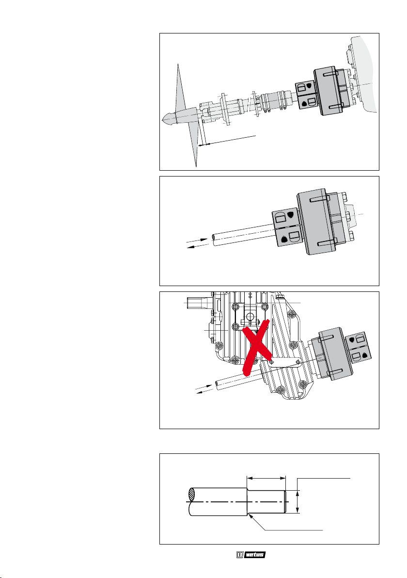
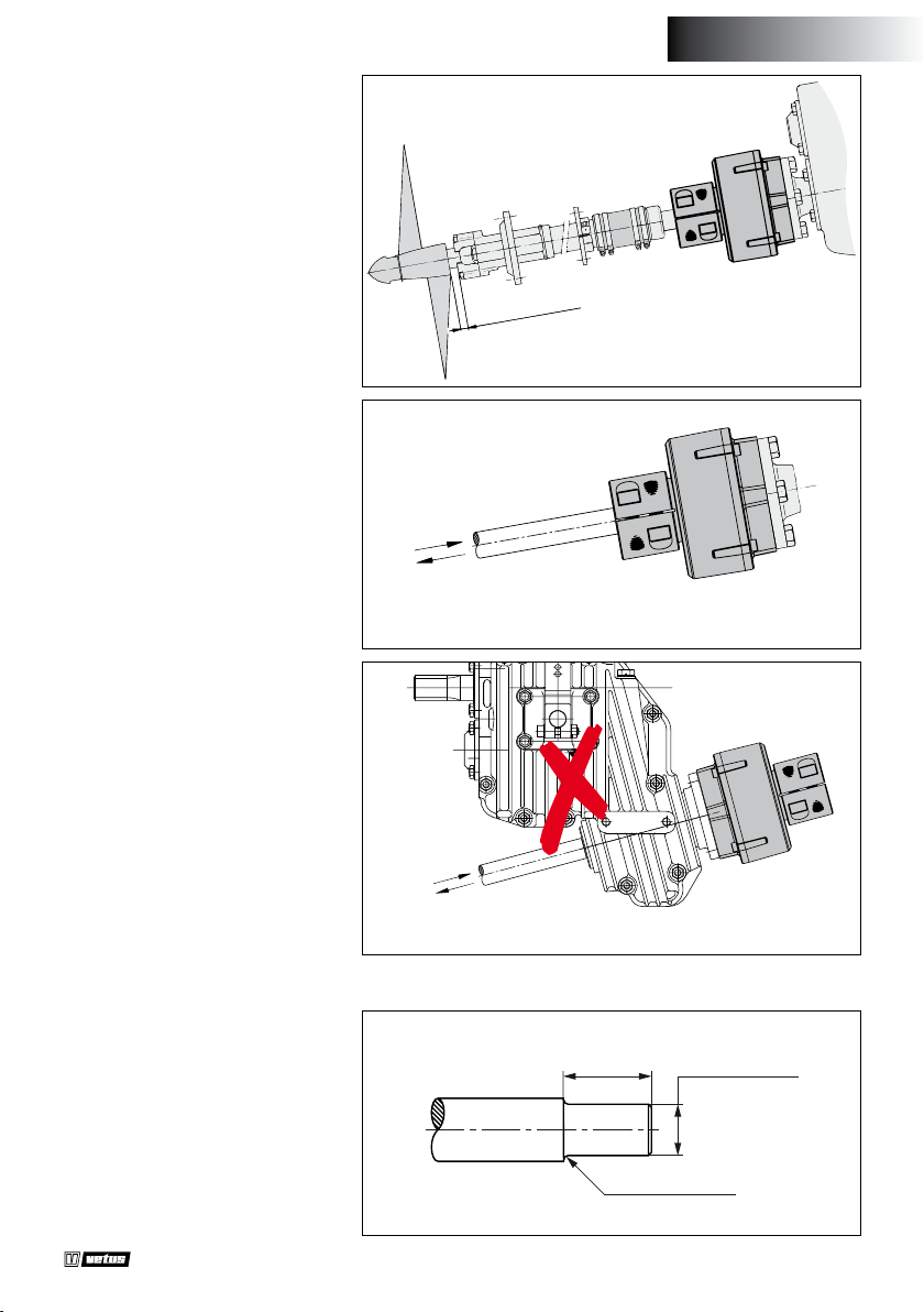
1 Opstelling
In verband met de axiale beweging van de schroefas moet er tussen het buitenlager en de naaf van
de scheepsschroef een minimale
vrije ruimte zijn.
2 Stuwkracht
N.B. Bij vooruit varen moet het
rubberdeel worden ingedrukt.
MIN. 10 mm
Duwend vooruit
Trekkend achteruit
Toepassing van de Combiex in
combinatie met een V-drive keerkoppeling is niet toegestaan!
Duwend vooruit
Trekkend achteruit
3 Afwijkende (grotere) schroefasdiameter
Verklein de schroefasdiameter
over de lengte van de klembus (afmeting ‘A’) naar afmeting ‘d’ van de
koppeling, zie ‘Hoofdafmetingen’.
Radius ‘r’ minimaal 2 mm.
4 030210.01
A
R = 2 mm
Propeller shaft coupling ‘Combiex’
ø ... h9
Page 5
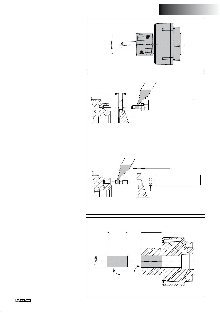
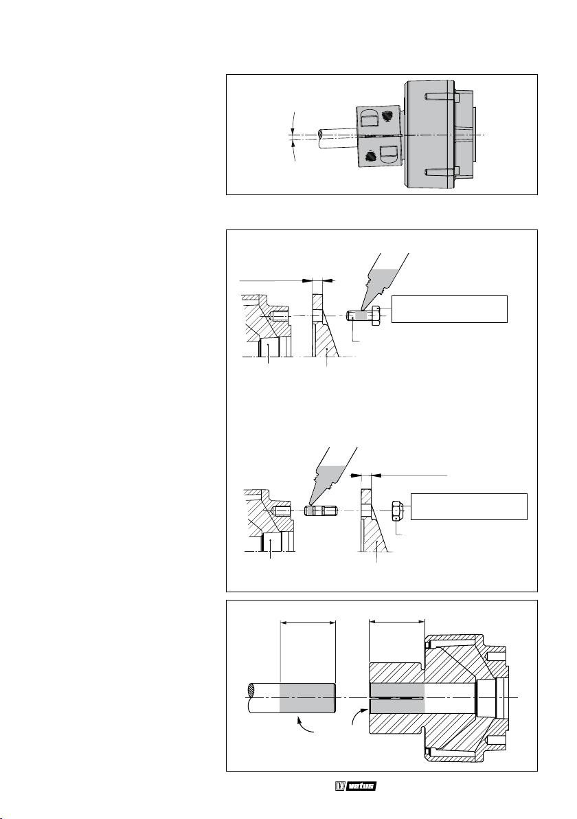
4 Uitlijnfout
De maximaal toelaatbare uitlijnfout van de schroefas is 2°.
2° MAX.
NEDERLANDS
5 Montage algemeen
Om een betrouwbaar functionerende koppeling te verkrijgen
dienen alle bouten en moeren
met de opgegeven momenten te
worden aangetrokken. Gebruik
hiervoor een momentsleutel; het
‘op gevoel’ aantrekken leidt niet
tot bevredigende resultaten.
De schroefas dient over de lengte
(L) in de naaf te zijn gestoken en as
en de naaf dienen vrij van vet en
vuil (*) te zijn.
MIN. 10 mm
MAX. 13 mm
COMBIFLEX
Koppeling
COMBIFLEX
Koppeling
LOCTITE 222 Screwlock
M10 x 25
Flens
LOCTITE 270 Studlock
Flens
L
Aanhaalmoment:
50 Nm (5 kg.m)
MAX. 10 mm
Aanhaalmoment:
50 Nm (5 kg.m)
M10 SELF-LOCKING
L
Propeller shaft coupling ‘Combiex’
* *
030210.01 5
Page 6
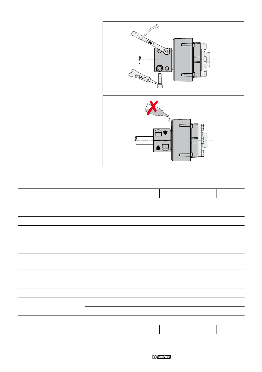
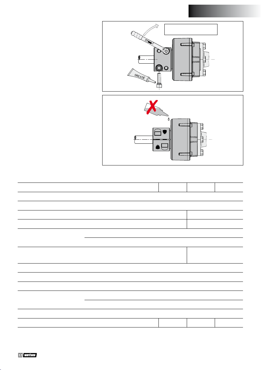
Trek de bouten aan met het opgegeven aanhaalmoment.
Aanhaalmoment:
100 Nm (10 kg.m)
Zorg er voor dat de rubberdelen
niet worden aangetast door op-
Oplosmiddelen
losmiddelen.
6 Technische gegevens
Type COMFL : 1225 1230 1325 1330
Max. koppel volgens DIN6270B : 250 Nm (25,5 kgf.m)
Max. koppel volgens DIN6270A : 212 Nm (21,6 kgf.m)
Max. vermogen volgens DIN6270B * : 5,2 kW/100 omw/min 2,4 kW/100 omw/min
Max. vermogen volgens DIN6270A * : 3,6 kW/100 omw/min 1,7 kW/100 omw/min
-4
2
Massatraagheidsmoment J : 230 10
2
GD
Dyn. torsiestijfheid :
: 0,01 kgf.m
870 Nm/rad
(6,59 °/100 Nm)
Axiale trekstijfheid : 1,7 kN/mm (173 kgf/mm)
Axiale drukstijfheid : 2,8 kN/mm (285 kgf/mm)
Max. hoekverplaatsing : 2°
Max. toerental bij
2° : 1500 omw/min
0° : 4500 omw/min
Max. stuwkracht : 10 kN (1019 kgf)
Gewicht : 3,5 kg 3,2 kg 3,5 kg 3,2 kg
kg.m
2
600 Nm/rad
(9,55 °/100 Nm)
* Max. vermogen: P
6 030210.01
max
= M
. 2 . π . n(M
max
is het max. koppel en n het toerental)
max
Propeller shaft coupling ‘Combiex’
Page 7
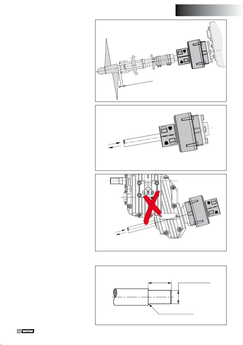
1 Mounting
In connection with the axial
movement of the propeller shaft
a minimum free space between
outer bearing and propeller hub
is required.
2 Propeller-thrust
N.B. When sailing in forward direction the rubber part must be compressed.
Using the Combiex in combination with a V-drive type gearbox is
not allowed!
MIN. 10 mm (
Push forward
Pull Reverse
ENGLISH
”)
3
/
8
Push forward
Pull Reverse
3 Over-size (larger) propeller shaft diameter
Reduce the propeller shaft diameter for the taper length (dimension ‘A’) to the given dimension
‘d’ of the coupling, see Overall dimensions. Radius ‘r’ minimal 2 mm
(1/16”).
Propeller shaft coupling ‘Combiex’
A
R = 2 (1/16”)
... h9 DIA
030210.01 7
Page 8
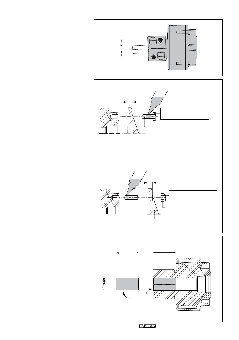
4 Misalignment
The maximum allowable misalignment of the propeller shaft is 2˚.
2° MAX.
5 General assembly
To achieve a reliably operating
coupling all the bolts and nuts
must be tightened with the torques given. Use a torque wrench;
tightening it ‘in the blind’ will not
lead to satisfying results.
The propeller shaft must be inserted into the hub for a sucient
length (L) and the shaft and hub
must be free of grease and dirt (*).
MIN. 10 mm (
MAX. 13 mm (
COMBIFLEX
Coupling
COMBIFLEX
Coupling
3
LOCTITE 270 Studlock
LOCTITE 222 Screwlock
/8”)
1
/2”)
Flange
L
M10 x 25
Flange
Tightening torque:
50 Nm (5 kg.m, 36 lbf.ft)
3
MAX. 10 mm (
M10 SELF-LOCKING
L
/8”)
Tightening torque:
50 Nm (5 kg.m, 36 lbf.ft)
8 030210.01
* *
Propeller shaft coupling ‘Combiex’
Page 9
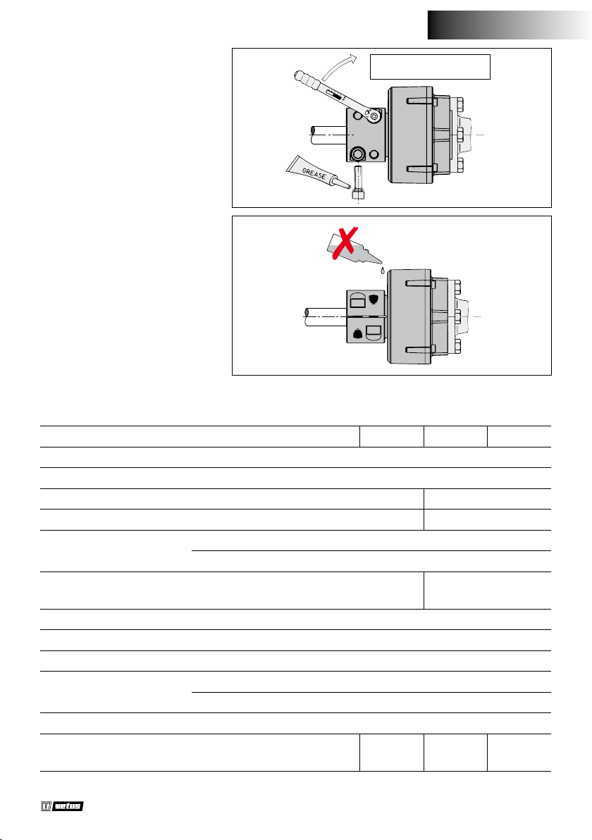
ENGLISH
Tighten the bolts with the specied torque.
Tightening torque:
100 Nm (10 kg.m, 72 lbf.ft)
Take care that the rubber parts are
not aected by solvents.
Solvents
6 Technical data
Type COMFL : 1225 1230 1325 1330
Max. torque to DIN6270B : 250 Nm (184 ft.lb)
Max. torque to DIN6270A : 212 Nm (156 ft.lb)
Max. power to DIN6270B * : 5,2 kW/100 rpm 2,4 kW/100 rpm
Max. power to DIN6270A * : 3,6 kW/100 rpm 1,7 kW/100 rpm
-4
2
Mass moment of inertia J : 230 10
2
GD
Dyn. torsion stiness :
: 0.01 kgf.m
870 Nm/rad
(8.93 °/100 ft.lb)
Axial pull stiness : 1.7 kN/mm (0.0103 inch/100 lbf)
Axial push stiness : 2.8 kN/mm (0.0063 inch/100 lbf)
Maximum angular displacement : 2°
Max. rpm at 2° : 1500 rpm
0° : 4500 rpm
Max. thrust force : 10 kN (2248 lbf)
Weight, approx. : 3.5 kg
(7.7 lbs)
3.2 kg
(7.1 lbs)
kg.m
2
600 Nm/rad
(12.95 °/100 ft.lb)
3.5 kg
(7.7 lbs)
3.2 kg
(7.1 lbs)
* Max. Power: P
Propeller shaft coupling ‘Combiex’
max
= M
. 2 . π . n(M
max
is the max. torque and n the RPM)
max
030210.01 9
Page 10
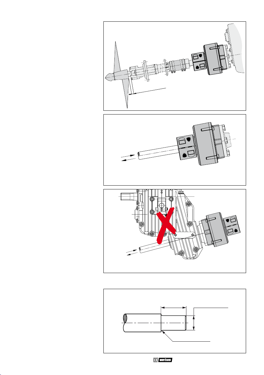
DEUTSCH
1 Aufstellung
Aufgrund der Achsialbewegung
der Schraubenwelle muß zwischen dem außeren Wellenlager
und der Nabe der Schisschraube
ein minimaler freier Raum sein.
2 Schubkraft
Achtung: Beim Vorwärtsfahren
soll das Gummiteil zusammengedrückt werden.
MIN. 10 mm
Druck - vorwärts
Zug - rückwärts
Der Einsatz der Combiex in Kombination mit einem Vdrive-Wendegetriebe ist nicht gestattet!
Druck - vorwärts
Zug - rückwärts
3 Abweichender (grösserer) durchmesser der schraubenwelle
Den Durchmesser der Schraubenwelle über die Länge der
Klemmbuchse (Maß ‘A’) auf Maß
‘d’ der Kupplung verkleinern, siehe
Hauptmaße. Radius ‘r’ sollte mindestens 2 mm betragen.
10 030210.01
A
R = 2 mm
Propeller shaft coupling ‘Combiex’
ø ... h9
Page 11
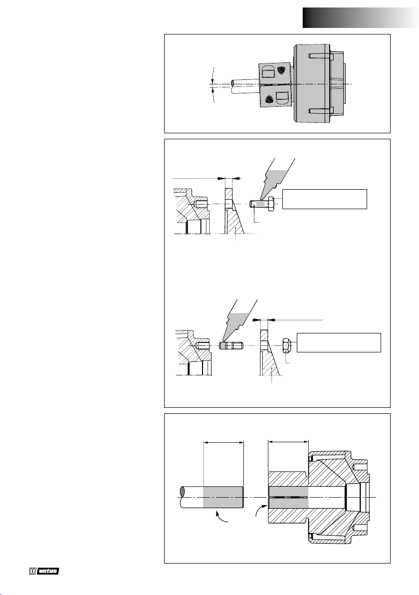
4 Versatz
Der max. zulässiger Versatz der
Schraubenwelle beträgt 2˚.
2° MAX.
DEUTSCH
5 Montage allgemein
Damit eine zuverlässig funktionierende Kupplung erreicht wird,
sollten alle Bolzen und Muttern
nach den angegebenen Drehmomenten angezogen werden.
Verwenden Sie dazu einen Drehmomentschlüssel; das ‘Anziehen
nach Gefühl’ führt nicht zu befriedigenden Ergebnissen.
Die Schraubenwelle muß über
genügenden Länge (L) in der
Klemmnabe und Schraubenwelle
müssen Schmutz- und fettfrei sein
(*).
MIN. 10 mm
MAX. 13 mm
COMBIFLEX
Kupplung
COMBIFLEX
Kupplung
LOCTITE 222 Screwlock
M10 x 25
Flansch
LOCTITE 270 Studlock
Flansch
L
Anzugsmoment:
50 Nm (5 kg.m)
MAX. 10 mm
Anzugsmoment:
50 Nm (5 kg.m)
M10 SELF-LOCKING
L
Propeller shaft coupling ‘Combiex’
* *
030210.01 11
Page 12
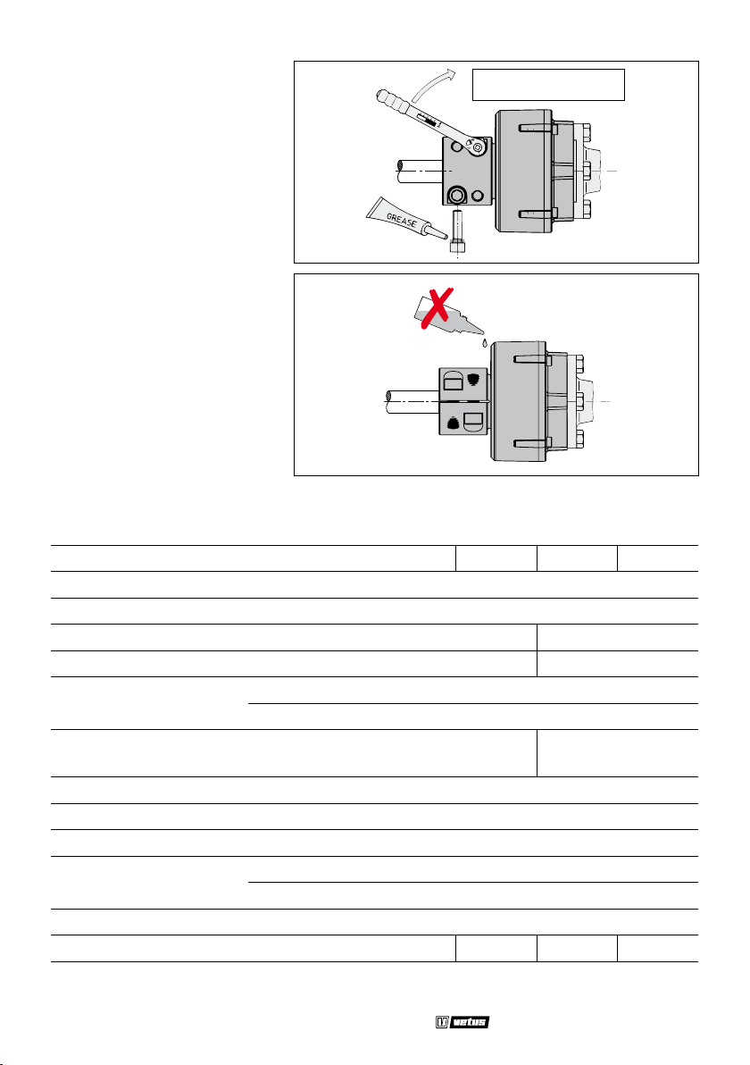
Ziehen Sie die Bolzen an mit der
angegebenen Anzugsmoment
Anzugsmoment:
100 Nm (10 kg.m)
Sorgen Sie dafür, daß die Gummiteile nicht von Lösungsmitteln
Lösungsmitteln
angegrien werden.
6 Technische Daten
Typ COMFL : 1225 1230 1325 1330
Max. Drehmoment gemäß DIN6270B : 250 Nm (25,5 kgf.m)
Max. Drehmoment gemäß DIN6270A : 212 Nm (21,6 kgf.m)
Max. Leistung gemäß DIN6270B * : 5,2 kW/100 U/min 2,4 kW/100 U/min
Max. Leistung gemäß DIN6270A * : 3,6 kW/100 U/min 1,7 kW/100 U/min
-4
2
Massenträgheitsmoment J : 230 10
GD2 : 0,01 kgf.m
Dyn. Drehsteigkeit :
870 Nm/rad
(6,59 °/100 N.m)
Axiale steigkeit zug : 1,7 kN/mm (173 kgf/mm)
Axiale steigkeit druck : 2,8 kN/mm (285 kgf/mm)
Max. Winkelverschiebung : 2°
Max. Drehzahl bei 2° : 1500 U/min
0° : 4500 U/min
Max. Triebkraft : 10 kN (1019 kgf)
Gewicht, ca. : 3,5 kg 3,2 kg 3,5 kg 3,2 kg
kg.m
2
600 Nm/rad
(9,55 °/100 N.m
* Max. Leistung: P
12 030210.01
max
= M
. 2 . π . n(M
max
ist das max. Drehmoment und n die Drehzahl)
max
Propeller shaft coupling ‘Combiex’
Page 13
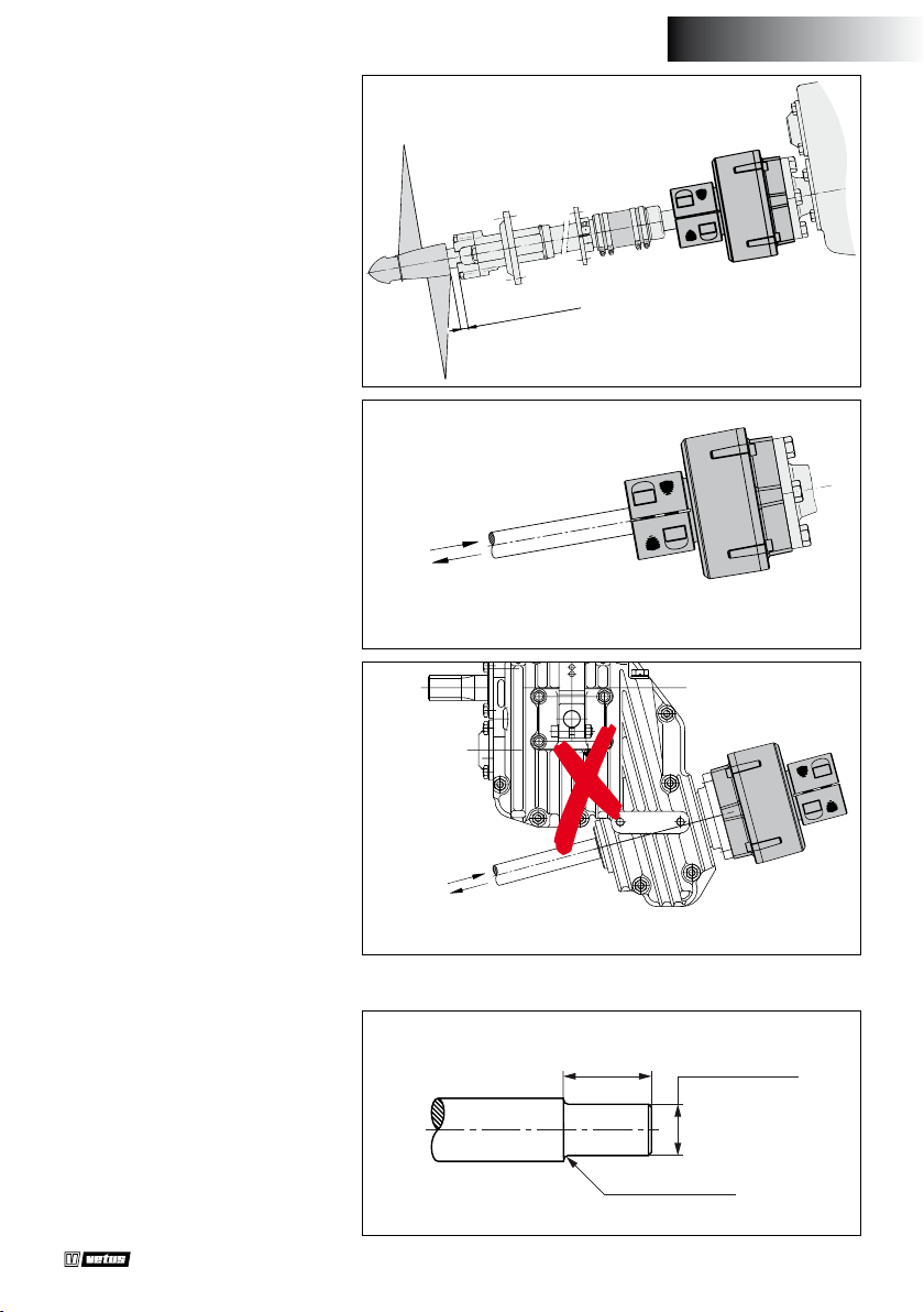
1 Montage
Etant donné le mouvement axial
de l’arbre porte-hélice, il est nécessaire de laisser un espace libre
minimum entre le support extérieur et le moyeu de l’hélice.
2 Force de propulsion
N.B. Lors de la marche avant, la
partie caoutchouc doit être comprimée.
Il est interdit d’utiliser le Combiex
en combinaison avec un inverseur
à entraînement en V !
MIN. 10 mm
Pousser - en avant
Tirer - en arrière
FRANÇAIS
Pousser - en avant
Tirer - en arrière
3 Autre diametre (plus grand) de l’arbre porte-helice
Réduire, sur la longueur de la
bague de serrage (dimension ‘A’),
le diamètre de l’arbre porte-hélice à la dimension ‘d’ du couplage.
Voir les dimensions principales.
Rayon ‘r’ minimum 2 mm.
Propeller shaft coupling ‘Combiex’
A
R = 2 mm
ø ... h9
030210.01 13
Page 14
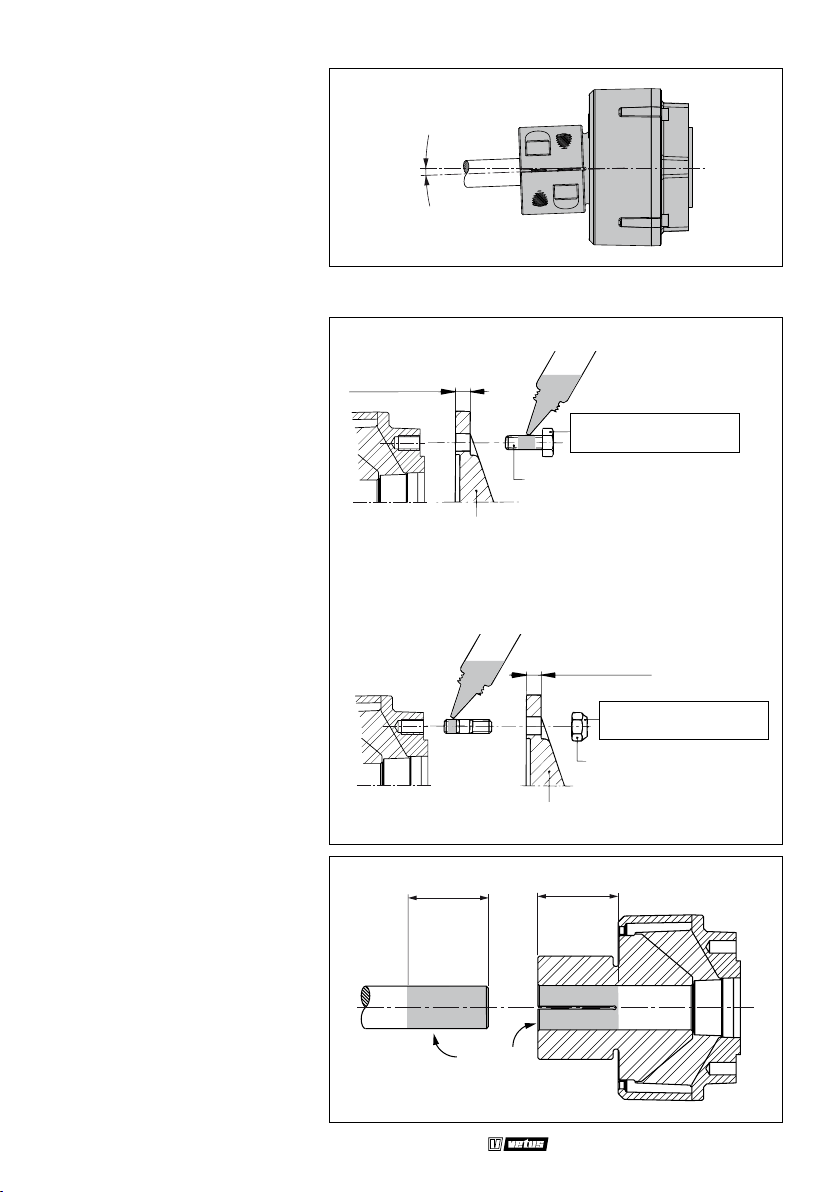
4 Desalignement
Le désalignement maximum autorisé de l’arbre porte-hélice est de
2˚.
5 Assemblage generalites
2° MAX.
Pour obtenir un accouplement
au fonctionnement able, il est
nécessaire de serrer tous les boulons et écrous selon les moments
indiqués. Utiliser pour cela une
clef dynamométrique; un serrage
approximatif ne donne pas de
résultats satisfaisants.
L’arbre de l’hélice doit être mis
dans le moyeu de longeur (L) sufsante. Veiller à ce que l’arbre et le
moyeu soient exempts de graisse
et de saleté (*).
MIN. 10 mm
MAX. 13 mm
COMBIFLEX
Accouplement
COMBIFLEX
Accouplement
LOCTITE 222 Screwlock
M10 x 25
Bride
LOCTITE 270 Studlock
Bride
L
Couple de serrage:
50 Nm (5 kg.m)
MAX. 10 mm
Couple de serrage:
50 Nm (5 kg.m)
M10 SELF-LOCKING
L
14 030210.01
* *
Propeller shaft coupling ‘Combiex’
Page 15
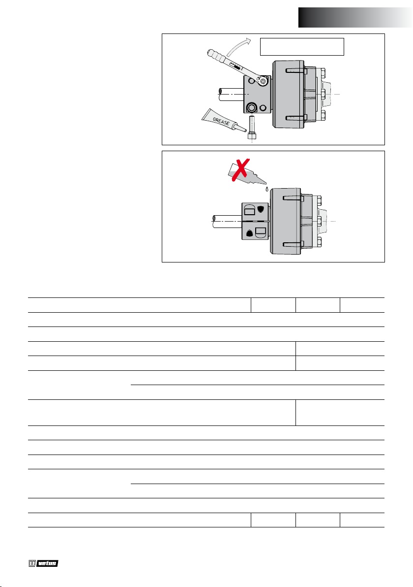
FRANÇAIS
Attirer les boulons à l’aide de la
torsion.
Veiller à ce que les parties caoutchouc ne soient pas attaquées par
des solvants.
Couple de serrage:
100 Nm (10 kg.m)
Solvants
6 Specications techniques
Type COMFL : 1225 1230 1325 1330
Couple max. selon DIN6270B : 250 Nm (25,5 kgf.m)
Couple max. selon DIN6270A : 212 Nm (21,6 kgf.m)
Puissance max. selon DIN6270B * : 5,2 kW/100 t.p.m. 2,4 kW/100 t.p.m.
Puissance max. selon DIN6270A * : 3,6 kW/100 t.p.m. 1,7 kW/100 t.p.m.
-4
2
Momente d’inertie J : 230 10
GD2 : 0,01 kgf.m
Rigidite dyn. a la torsion :
Rigidite axiale a la traction : 1,7 kN/mm (173 kgf/mm)
Rigidite axiale a la compression : 2,8 kN/mm (285 kgf/mm)
Le deplacement angulaire max. : 2°
Nombre de tours max. á 2° : 1500 t.p.m.
0° : 4500 t.p.m.
Poussée max. : 10 kN (1019 kgf )
Poids, environ : 3,5 kg 3,2 kg 3,5 kg 3,2 kg
870 Nm/rad
(6,59 °/100 N.m)
kg.m
2
600 Nm/rad
(9,55 °/100 N.m)
* Puissance max. Pmax = Mmax . 2 . π . n(Mmax est le couple max. et n le nombre de tours)
Propeller shaft coupling ‘Combiex’
030210.01 15
Page 16
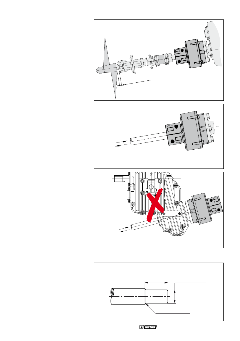
ESPAÑOL
1 Montaje
Dado el movimiento axial del árbol porta-hélice, es necesario dejar un espacio libre mínimo entre
el soporte exterior y el cubo de
hélice.
2 Fuerza de propulsión
Nota: ¡Navegando hacia delante
la parte de caucho se debe comprimir!
MIN. 10 mm
Empujando - delante
Tirando - atrás
¡No se permite aplicar el Combiex en combinación con la caja de
velocidades del tipo de transmisión en V!
Empujando - delante
Tirando - atrás
3 Otro diámetro (mayor) del árbol porta-hélice
Redúzcase el diámetro del árbol
porta-hélice a lo largo del cono
(dimensión ‘A’) hacia dimensión ‘d’
del acoplamiento, véanse las Dimensiones Principales. El radio ‘r’
será de 2 mm como mínimo.
16 030210.01
A
R = 2 mm
Propeller shaft coupling ‘Combiex’
ø ... h9
Page 17
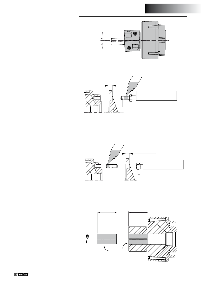
4 Mal alineamiento
Se admite un mal alineamiento
máximo de 2˚ del árbol portahélice.
2° MAX.
ESPAÑOL
5 Montaje en general
Para obtener una acoplamiento
de funcionamiento able se apretarán todos los tornillos y tuercas
según los pares indicados. Utilizar para ello una llave de torsión;
apretar ‘a tientas’ no dará resultados satisfactorios.
El árbol porta-hélice se insertará
con un largo (L) suciente en el
cubo y el árbol y cubo estarán limpios de grasa y suciedad (*).
MIN. 10 mm
MAX. 13 mm
COMBIFLEX
Acoplamiento
COMBIFLEX
Acoplamiento
LOCTITE 222 Screwlock
M10 x 25
Brida
LOCTITE 270 Studlock
Brida
L
Par de apriete:
50 Nm (5 kg.m)
MAX. 10 mm
Par de apriete:
50 Nm (5 kg.m)
M10 SELF-LOCKING
L
Propeller shaft coupling ‘Combiex’
* *
030210.01 17
Page 18
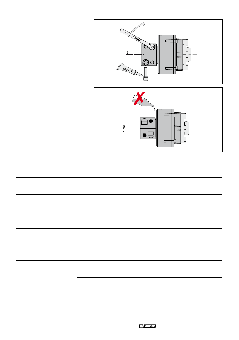
Apretar los tornillos observando el
par indicado.
Par de apriete:
100 Nm (10 kg.m)
Asegurar que las partes de caucho
no sean afectadas por disolventes.
Disolventes
6 Especications techniques
Tipo COMFL : 1225 1230 1325 1330
Par máximo según DIN6270B : 250 Nm (25,5 kgf.m)
Par máximo según DIN6270A : 212 Nm (21,6 kgf.m)
Potencia máximo según DIN6270B * : 5,2 kW/100 v/min 2,4 kW/100 v/min
Potencia máximo según DIN6270A * : 3,6 kW/100 v/min 1,7 kW/100 v/min
-4
2
Momento de inercia J : 230 10
GD2 : 0,01 kgf.m
Rigidez dyn. de torsión :
870 Nm/rad
(6,59 °/100 N.m)
Rigidez axial de tracción : 1,7 kN/mm (173 kgf/mm)
Rigidez axial de compresión : 2,8 kN/mm (285 kgf/mm)
Desplazamiento angular máx. : 2°
Número de revoluciones
máx. con
2° : 1500 v/min
0° : 4500 v/min
Fuerza de propulsión máx. : 10 kN (1019 kgf )
Peso, aprox. : 3,5 kg 3,2 kg 3,5 kg 3,2 kg
kg.m
2
600 Nm/rad
(9,55 °/100 N.m)
* Potencia máxima: P
ciones)
18 030210.01
max
= M
. 2 . π. n(siendo ‘M
max
’ el par máximo y ‘n’ el número de revolu-
max
Propeller shaft coupling ‘Combiex’
Page 19
1 Montaggio
Tenendo conto del movimento
assiale dell’albero dell’elica, è necessario lasciare uno spazio libero
minimo fra la sospensione esterna
e il mozzo dell’elica.
2 Forza di propulsione
N.B. Durante la marcia in avanti la
parte in gomma deve essere premuta!
L’uso del Combiex in combinazione con una trasmissione tipo
V-drive non è permesso!
MIN. 10 mm
Spinta - avanti
Trazione - indietro
ITALIANO
Spinta - avanti
Trazione - indietro
3 Diametro diverso (più grande) dell’albero dell’elica
Ridurre il diametro dell’albero
dell’elica sulla lunghezza del fermo (dimensione ‘A’) no a raggiungere la dimensione ‘d’ dell’accoppiamento, vedi Dimensioni
Principali. Raggio ‘r’ minimo 2 mm.
Propeller shaft coupling ‘Combiex’
A
R = 2 mm
ø ... h9
030210.01 19
Page 20
4 Errore di allineamento
L’errore di allineamento massimo
consentito dell’albero dell’elica è
di 2˚.
5 Montaggio, generalità
2° MAX.
Per ottenere un giunto di accoppiamento che funzioni in modo
adabile, tutti i bulloni e tutti i
dadi devono essere avvitati con
il momento indicato. A questo
scopo utilizzare una chiave dinamometrica; avvitando in modo
approssimativo non si ottengono
risultati soddisfacenti.
L’albero dell’elica deve essere inserito nel mozzo per una lunghezza
suciente (L) e sia l’albero che il
mozzo devono essere privi di grasso e di sporco (*).
MIN. 10 mm
MAX. 13 mm
COMBIFLEX
Giunto di
accopiamento
COMBIFLEX
Giunto di accopiamento
Flangia
LOCTITE 270 Studlock
L
LOCTITE 222 Screwlock
Coppia di serraggio:
50 Nm (5 kg.m)
M10 x 25
MAX. 10 mm
Coppia di serraggio:
50 Nm (5 kg.m)
M10 SELF-LOCKING
Flangia
L
20 030210.01
* *
Propeller shaft coupling ‘Combiex’
Page 21
ITALIANO
Stringere i bulloni con il momento
indicato.
Coppia di serraggio:
100 Nm (10 kg.m)
Assicurarsi che le parti in gomma
non vengano corrose dai solventi.
Solventi
6 Dati tecnici
Tipo COMFL : 1225 1230 1325 1330
Momento max. secondo DIN6270B : 250 Nm (25,5 kgf.m)
Momento max. secondo DIN6270A : 212 Nm (21,6 kgf.m)
Potenza max. secondo DIN6270B * : 5,2 kW/100 giri/min 2,4 kW/100 giri/min
Potenza max. secondo DIN6270A * : 3,6 kW/100 giri/min 1,7 kW/100 giri/min
-4
2
Momento d’inerzia J : 230 10
GD2 : 0,01 kgf.m
Rigidità torsionale din. :
870 Nm/rad
(6,59 °/100 N.m)
Rigidità assiale alla trazione : 1,7 kN/mm (173 kgf/mm)
Rigidità assiale alla compressione : 2,8 kN/mm (285 kgf/mm)
Spostamento angolare massimo : 2°
Numero max. di giri a 2° : 1500 giri/min
0° : 4500 giri/min
Propulsione max. : 10 kN (1019 kgf )
Peso, circa : 3,5 kg 3,2 kg 3,5 kg 3,2 kg
kg.m
2
600 Nm/rad
(9,55 °/100 N.m)
* Potenze massima: P
di giri)
Propeller shaft coupling ‘Combiex’
max
= M
. 2 . π . n(dove M
max
indica la coppia massima ed ‘n’ il numero
max
030210.01 21
Page 22
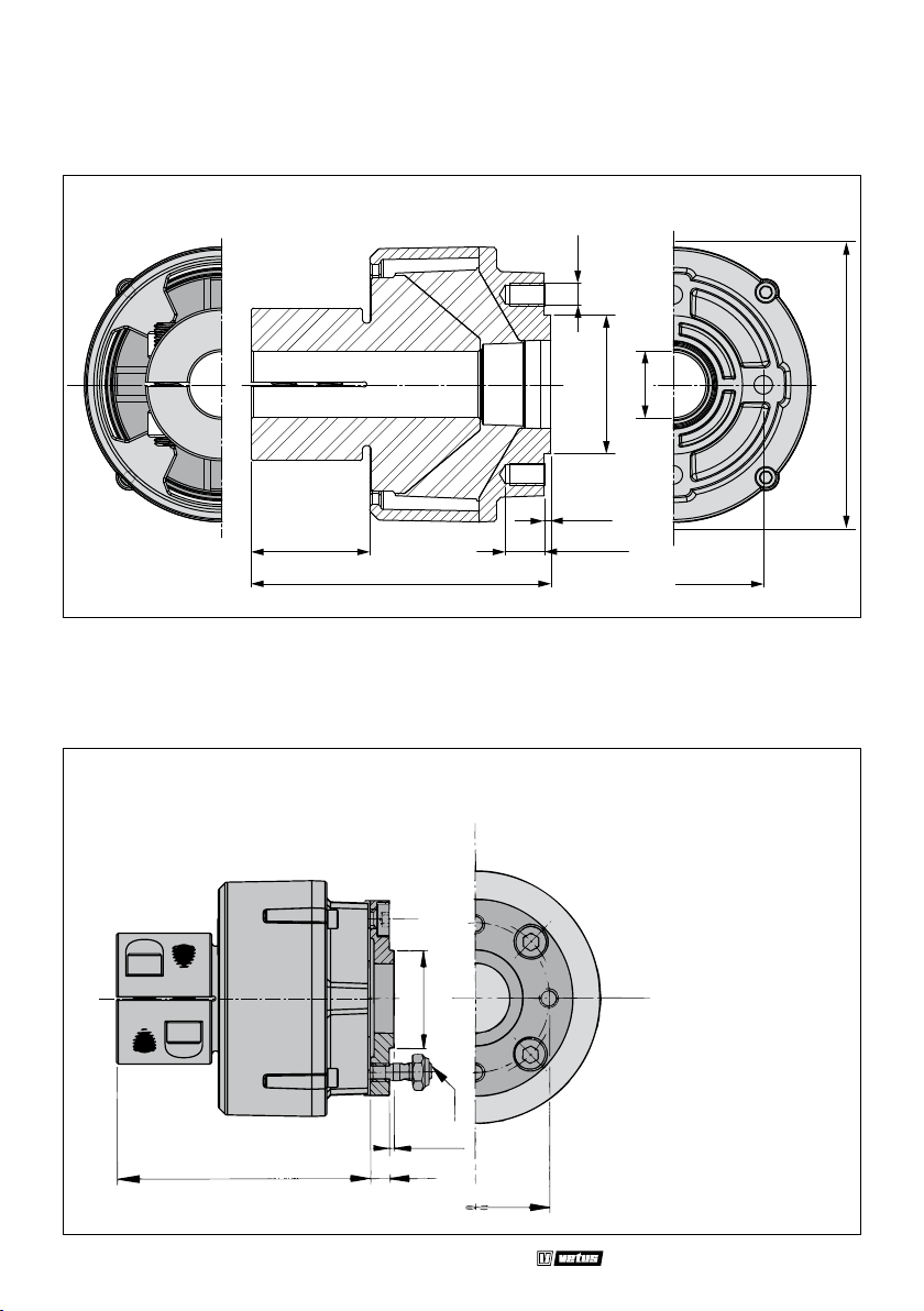
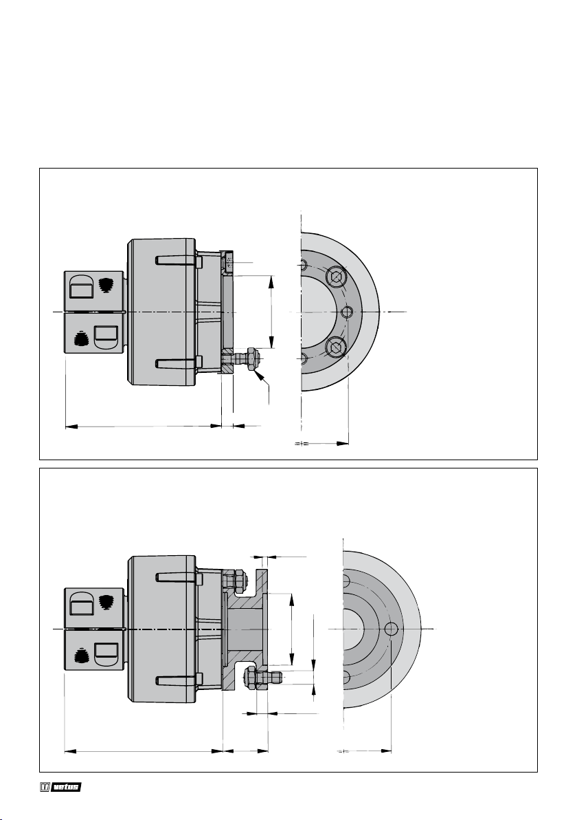
7 Hoofdafmetingen
Hauptabmessungen
Dimensiones principales
Principal dimensions
54 (1
Dimensions principales
1
/8”)
137
(5 3/8”)
M10
” DIA.)
/
ø 63.5
1
2
(
3 (1/8”)
11
18 (
Dimensioni principali
d
2
/16”)
ø 82.5
(
3 1/4” PCD)
8 Verloopenzen Zwischenanschen Bridas de adaptación
Adapter anges Brides d’adaptation Flange di adattamento
” DIA.)
16
/
3
5
ø 132 (
FLANGE1
22 030210.01
134 (5
1
/4”)
”)
32
/
31
50 (1
2 (5/64”)
11,5 (29/64”)
M10
78 (3
5
/64”)
- KANZAKI KC30
KC45
KC100
- YANMAR KM2C
KM2P
KM3A
KM3P
Propeller shaft coupling ‘Combiex’
Page 23
FLANGE2
134 (5 1/4”)
- VOLVO MS10A MS10L
MS15A MS15L
MS25A MS25L
”)
64
/
23
60 (2
M10
11,5 (29/64”)
80 (3
5
/32”)
FLANGE2A
Propeller shaft coupling ‘Combiex’
134 (5
1
/4”)
4 (5/32”)
38 (1 1/2”)
”)
”)
64
/
16
/
23
7
60 (2
ø 11 (
10 (13/32”)
- VOLVO MS
MSB
MS2
5
/32”)
80 (3
030210.01 23
Page 24

Fokkerstraat 571 - 3125 BD Schiedam - The Netherlands
Tel.: +31 (0)88 4884700
[email protected] - www.vetus.com
Printed in the Netherlands
030210.01 2022-07
 Loading...