

Vetus BOW25 Series, BOW60 Series, BOW45 Series, BOW55 Series, BOW75 Series Installation Recommendations [en, fr]
...Page 1

NEDERLANDS 4
ENGLISH 12
DEUTSCH 20
FRANÇAIS 28
ESPAÑOL 36
ITALIANO 44
Installatieaanbevelingen
voor boegschroeven
Einbauhinweise
für Bugschrauben
Recommandations
pour l’installation d’hélices d’étrave
Recomendaciones
de instalación para hélices de proa
Suggerimenti per l’installazione
delle eliche di prua
A
BOW25 . . .
BOW35 . . .
BOW45 . . .
Installation recommendations
for bow thrusters
BOW55 . . .
BOW60 . . .
BOW75 . . .
Copyright © 2017 Vetus b.v. Schiedam Holland
BOW95 . . .
BOW125 . . .
BOW160 . . .
BOW220 . . .
BOW285 . . .
BOW230 . . .
BOW310 . . .
BOW410 . . .
BOW550 . . .
020571.04
Page 2

Inhoud Content Inhalt
1 Opstelling van de tunnelbuis. . . . 4
2 Opstelling boegschroef in tun-
nelbuis . . . . . . . . . . . . . . . . . . 5
3 Overgang van tunnelbuis naar
scheepsromp . . . . . . . . . . . . . . 6
4 Spijlen in de tunnelbuis-openin-
gen. . . . . . . . . . . . . . . . . . . . . 7
5 Aanbrengen van de tunnelbuis . . 8
6 Aanbrengen van de gaten in de
tunnelbuis . . . . . . . . . . . . . . . . 9
7 Bescherming van de boeg-
schroef tegen corrosie . . . . . . . . 9
8 De stroomverzorging . . . . . . . . 10
8.1 De keuze van de accu . . . . . . . . 10
8.2 Hoofdstroomkabels (accukabels) . 10
8.3 Hoofdschakelaar . . . . . . . . . . . 10
8.4 Zekering. . . . . . . . . . . . . . . . . 11
8.5 Serie-parallelschakelaar . . . . . . . 11
9 Boegschroefbedieningen . . . . . 11
9.1 Tijdvertraging bij omkeren van
de draairichting . . . . . . . . . . . . 11
1 Positioning of thrust tunnel. . . . 12
2 Positioning of the bow thruster
in the thrust-tunnel . . . . . . . . . 13
3 Connection of thrust tunnel to
ship’s hull . . . . . . . . . . . . . . . . 14
4 Grid bars in the tunnel openings 15
5 Installation of the thrust tunnel . 16
6 Drilling the holes in the thrust-
tunnel . . . . . . . . . . . . . . . . . . 17
7 Protection of the bow thruster
against corrosion. . . . . . . . . . . 17
8 The power supply . . . . . . . . . . 18
8.1 Choice of battery . . . . . . . . . . . 18
8.2 Main power cables (battery
cables) . . . . . . . . . . . . . . . . . . 18
8.3 Main Switch . . . . . . . . . . . . . . 18
8.4 Fuse . . . . . . . . . . . . . . . . . . . 19
8.5 Series-parallel switch. . . . . . . . . 19
9 Bow thruster operation . . . . . . 19
9.1 Delay when reversing the turn
direction . . . . . . . . . . . . . . . . 19
1 Aufstellung vom tunnelrohr . . . 20
2 Aufstellung der Bugschraube
ins Tunnelrohr. . . . . . . . . . . . . 21
3 Übergang vom tunnelrohr zum
schisrumpf . . . . . . . . . . . . . . 22
4 Gitterstäbe in den Tunnelrohröf-
fnungen. . . . . . . . . . . . . . . . . 23
5 Anbringen vom Tunnelrohr . . . . 24
6 Anbringen der Löcher ins Tun-
nelrohr . . . . . . . . . . . . . . . . . 25
7 Korrosionsschutz der bug-
schraube . . . . . . . . . . . . . . . . 25
8 Stromversorgung . . . . . . . . . . 26
8.1 Wahl des Akku. . . . . . . . . . . . . 26
8.2 Hauptstromkabel (Akkukabel). . . 26
8.3 Hauptschalter . . . . . . . . . . . . . 26
8.4 Sicherung. . . . . . . . . . . . . . . . 27
8.5 Serien-/Parallelschalter . . . . . . . 27
9 Bugschrauben-Bedienungsele-
mente . . . . . . . . . . . . . . . . . . 27
9.1 Zeitverzögerung bei Umkehr der
Drehrichtung . . . . . . . . . . . . . 27
Sommaire Índice Indice
1 Position de la tuyere . . . . . . . . 28
2 Position de l’hélice d’étrave
dans la tuyere . . . . . . . . . . . . . 29
3 Adaption de la tuyère à l’étrave . 30
4 Barres dans les ouvertures de la
tuyère . . . . . . . . . . . . . . . . . . 31
5 Installation de la tuyère . . . . . . 32
6 Percer les trous dans la tuyère . . 33
7 Protection de l’helice d’etrave
contre la corrosion. . . . . . . . . . 33
8 L’alimentation électrique . . . . . 34
8.1 Le choix de la batterie . . . . . . . . 34
8.2 Câbles du courant principal
(câbles de la batterie) . . . . . . . . 34
8.3 Interrupteur principal . . . . . . . . 34
8.4 Fusible. . . . . . . . . . . . . . . . . . 35
8.5 Coupleur série - parallèle . . . . . . 35
9 Fonctionnement de l’hélice
d’étrave . . . . . . . . . . . . . . . . . 35
9.1 Temporisation lors de change-
ment de sens de rotation . . . . . . 35
1 Situar el conducto de propul-
sión . . . . . . . . . . . . . . . . . . . 36
2 Situar la hélice de proa en el
conducto de propulsión . . . . . . 37
3 Acoplamiento del conducto de
propulsión al casco . . . . . . . . . 38
4 Barras en los oricios del con-
ducto de propulsión . . . . . . . . 39
5 Instalación del conducto de
propulsión . . . . . . . . . . . . . . . 40
6 Perforación de los oricios en el
conducto de propulsión . . . . . . 41
7 Protección de la hélice de proa
contra la corrosión. . . . . . . . . . 41
8 El suministro de corriente . . . . . 42
8.1 La elección de batería . . . . . . . . 42
8.2 Cables de corriente principal
(cables de batería) . . . . . . . . . . 42
8.3 Interruptor principal . . . . . . . . . 42
8.4 Fusible. . . . . . . . . . . . . . . . . . 43
8.5 8.5 Interruptor paralelo en serie. . 43
9 Controles de la hélice de proa . . 43
9.1 Retardo en inversión de dirección
de giro. . . . . . . . . . . . . . . . . . 43
1 Collocazione del tunnel . . . . . . 44
2 Collocazione dell’elica di prua
nel tunnel . . . . . . . . . . . . . . . 45
3 Montaggio del tunnel allo scafo. 46
4 Sbarre nelle aperture del tunnel. 47
5 Installazione del tunnel . . . . . . 48
6 Come praticare i fori nel tunnel . 49
7 Protezione dell’elica di prua
contro la corrosione. . . . . . . . . 49
8 L’alimentazione. . . . . . . . . . . . 50
8.1 La scelta della batteria. . . . . . . . 50
8.2 Cavi (della batteria). . . . . . . . . . 50
8.3 Interruttore principale. . . . . . . . 50
8.4 Fusibile . . . . . . . . . . . . . . . . . 51
8.5 Interruttore serie-parallelo . . . . . 51
9 Comandi per elica di prua . . . . . 51
9.1 Ritardo dopo l’inversione della
rotazione . . . . . . . . . . . . . . . . 51
vetus® Installation recommendations for thrusters
020571.03 3
Page 3
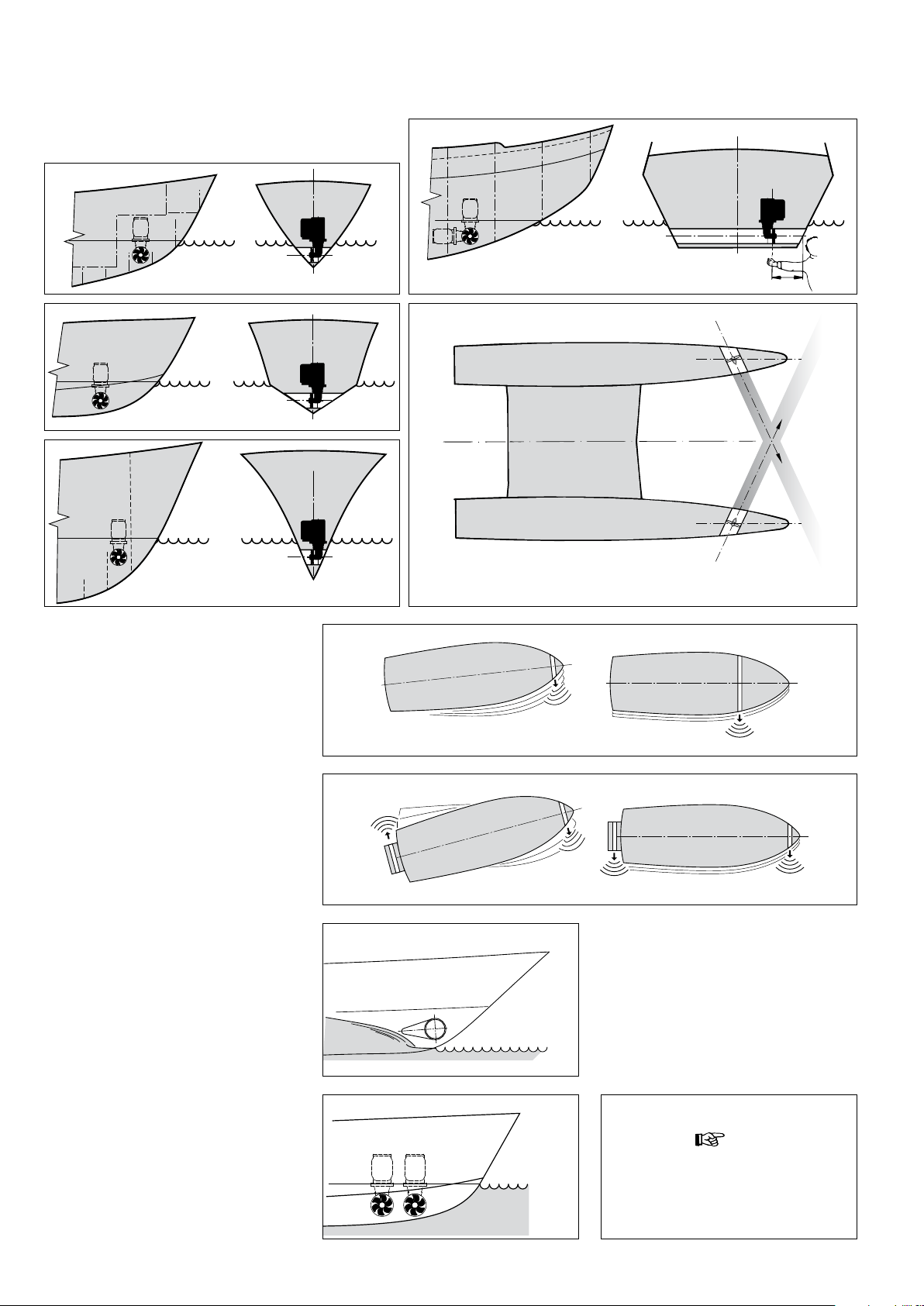
1 Positioning of thrust tunnel
Several installation examples.
To achieve the optimum performance, position the thrust tunnel as far forward as possible.
If, in addition to controlling the movement
of the bow, the stern of the vessel is required
to move sideways, then a second thruster
may be installed at the stern.
In case of a planning vessel the tunnel
should, if possible, be so situated that when
the vessel is planing it is above the water
level thus causing no resistance.
Set-up: 2 bow thrusters in a catamaran
Installation of two bow thrusters in tandem
(for larger boats). In this case, depending on
weather conditions, one or both bow thrusters may be used.
12 020571.03
Tip:
We do not advise tting 2 bow thrusters
into one tunnel; this does not result in
doubling the thrust!
vetus® Installation recommendations for thrusters
Page 4

ENGLISH
When choosing the location for the thrust
tunnel, take the following into account for
optimum performance:
- The distance A shown in the drawing
must be at least 0.5 x D (where D is the
tunnel diameter).
- The length of the tunnel (distance B)
should be between 2 x D and 4 x D.
Thruster
‘BOW . . . . .’
25 . . . 110 (4
45 . . . 125 (4
35 . . . 55 . . . 150 (5
60 . . . 75 . . . 95 . . . 185 (7
125 . . . 160 . . . 250 (9
220 . . . 230 . . . 285 . . . 310 . . . 300 (11
410 . . . 550 . . . 400 (15
A
D
A
A
A = min. 0.5 x D
D
[mm]
(inches)
5
/16”) 55 (2 1/4”) 220 … 440 (9 … 18”)
15
/16”) 65 (2 9/16”) 250 … 500 (10 … 20”)
7
/8”) 75 (3”) 300 … 600 (12 … 24”)
5
/16”) 100 (4”) 370 … 740 (15 … 30”)
13
/16”) 125 (5”) 500 … 1000 (20 … 40”)
13
/16”) 150 (6”) 600 … 1200 (24 … 48”)
3
/4”) 200 (8”) 800 … 1600 (32 … 64”)
A
[mm]
(inches)
[mm]
(inches)
D
=
=
B
B = min. 2 x D
B
2 Positioning of the bow thruster in the thrust-tunnel
When determining the exact position of the
bow thruster in the thrust tunnel, it should
be taken into account that the tailpiece may
NOT protrude from the tunnel end.
The propeller should preferably be situated
on the centreline of the vessel, but it must
always be accessible from the outside.
The electric motor can be installed in various
positions.
If the motor is installed horizontally, a support is absolutely necessary.
The electric motor must be positioned in
such a way that it is always well clear from
the maximum bilge water level.
vetus® Installation recommendations for thrusters
180º
Max. bilge
water level
020571.03 13
Page 5
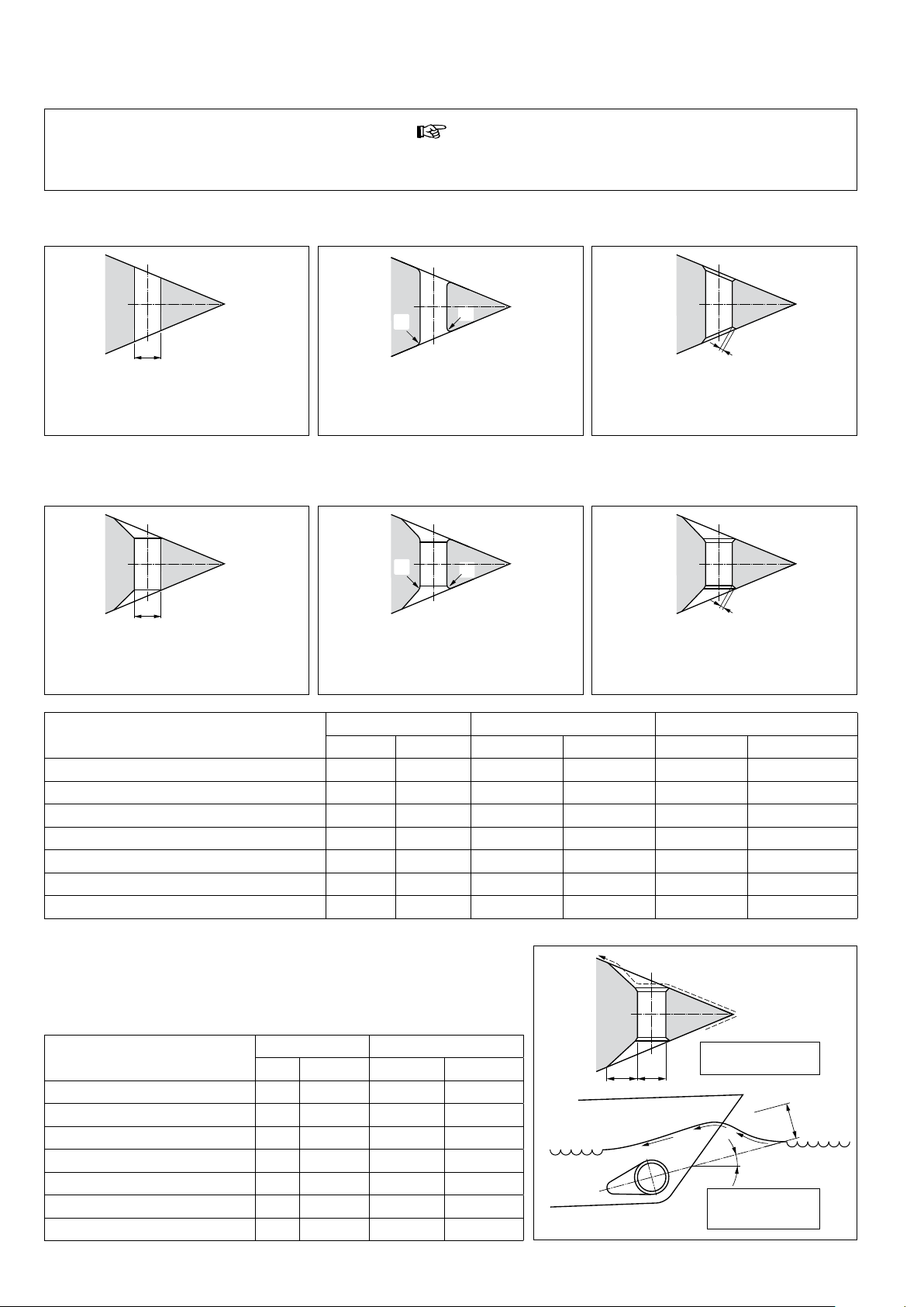
3 Connection of thrust tunnel to ship’s hull
Tip:
The manner, in which the thrust tunnel is connected to the ship’s hull, is of great inuence to the actual performance of the bow thruster
and to the drag that the hull produces when under way.
Direct connection of the tunnel to the hull, without a fairing, produces reasonable results.
R
R
D
The connection to the hull can be abrupt.
Connection of the thrust tunnel to the ship’s hull with a fairing results in lower hullresistance during normal sailing.
It is better to make the connection rounded with radius ‘R’ of about 0.1 x D.
R
R
D
The connection with a fairing can be
abrupt.
Thruster
‘BOW . . . . .’
25 . . . 110 (4
45 . . . 125 (4
35 . . . 55 . . . 150 (5
60 . . . 75 . . . 95 . . . 185 (7
125 . . . 160 . . . 250 (9
220 . . . 230 . . . 285 . . . 310 . . . 300 (11
410 . . . 550 . . . 400 (15
It is better to make the connection with a
fairing rounded with radius ‘R’ of about 0.1
x D.
D R C
[mm] (inches) [mm] (inches) [mm] (inches)
5
/16”) 11 (7/16”) 11 … 17 (7/16 … 11/16”)
15
/16”) 13 (1/2”) 13 … 19 (1/2 … 3/4”)
7
/8”) 15 (5/8”) 15 … 22 (5/8 … 7/8”)
5
/16”) 20 (3/4”) 20 … 30 (3/4 … 1 3/16”)
13
/16”) 25 (1”) 25 … 38 (1 … 1 1/2”)
13
/16”) 30 1 3/16”) 30 … 45 (1 3/16 … 1 3/4”)
3
/4”) 40 1 1/2”) 40 … 60 (1 1/2 … 2 3/8”)
C
It is even better to use sloping sides ‘C’ with
dimensions 0.1 to 0.15 x D.
C
The best connection is with a fairing using
sloping side ‘C’ with dimensions 0.1 to 0.15
x D.
Length ‘L’ of the fairing should be between 1 x D and 3 x D.
This fairing should be embodied in the ship’s hull in such a way that
the centreline of the fairing will correspond with the anticipated
shape of the bow-wave.
Thruster
‘BOW . . . . .’
25 . . . 110 (4
45 . . . 125 (4
35 . . . 55 . . . 150 (5
60 . . . 75 . . . 95 . . . 185 (7
125 . . . 160 . . . 250 (9
220 . . . 230 . . . 285 . . . 310 . . . 300 (11
410 . . . 550 . . . 400 (15
D L
[mm] (inches) [mm] (inches)
5
/16”) 110 ... 330 (4 1/2 ... 13”)
15
/16”) 125 ... 375 (5 ... 15”)
7
/8”) 150 ... 450 (6 ... 18”)
5
/16”) 200 ... 600 (8 ... 24”)
13
/16”) 250 ... 750 (10 ... 30”)
13
/16”) 300 ... 900 (12 ... 36”)
3
/4”) 400 ... 1200 (16 ... 48”)
14 020571.03
DL
L = 1 x D ... 3 x D
=
α
α : min. 0º
max. 15º
vetus® Installation recommendations for thrusters
Page 6

If the connection of the thrust tunnel and the ship’s hull is to be
made with a sloped side, it should be executed in accordance with
the drawing.
ENGLISH
Make the sloped side (C) with a length of 0.1 to 0.15 x D and make
sure that the angle between the tunnel and the sloped side will be
identical to the angle between the sloped side and the ship’s hull.
Thruster
‘BOW . . . . .’
25 . . . 110 (4
45 . . . 125 (4
35 . . . 55 . . . 150 (5
60 . . . 75 . . . 95 . . . 185 (7
125 . . . 160 . . . 250 (9
220 . . . 230 . . . 285 . . . 310 . . . 300 (11
410 . . . 550 . . . 400 (15
D C
[mm] (inches) [mm] (inches)
5
/16”) 11 … 17 (7/16 … 11/16”)
15
/16”) 13 … 19 (1/2 … 3/4”)
7
/8”) 15 … 22 (5/8 … 7/8”)
5
/16”) 20 … 30 (3/4 … 1 3/16”)
13
/16”) 25 … 38 (1 … 1 1/2”)
13
/16”) 30 … 45 (1 3/16 … 1 3/4”)
3
/4”) 40 … 60 (1 1/2 … 2 3/8”)
4 Grid bars in the tunnel openings
Although the thrust force will be adversely aected, grid bars may be placed into the tunnel
openings, for protection of the thruster.
In order to limit the negative eect of this on the thrust and on hull resistance during normal
operation as much as possible, the following must be taken into account:
β
γ
C
γ
Sharp
C = 0.1 x D ... 0.15 x D
C
β
β = β
γ = γ
Do not t more bars per opening than is indicated in the drawing.
The bars must have a rectangular cross-section.
Do not t round bars.
The bars must overlap a certain amount.
The bars must be installed so that they stand
perpendicular to the expected wave form.
2 x 3 x 4 x
110 mm
125 mm
ca. 0.7 x 0.7 mm
1
(
/32” x 1/32”)
min. 20 mm (
max. 40 mm (1
3 mm (1/8”)
150 mm
185 mm
3
/4”)
1
/2”)
Overlapping
=
250 mm
300 mm
400 mm
ø ...
vetus® Installation recommendations for thrusters
90º
α
α : min. 0º
max. 15º
020571.03 15
Page 7
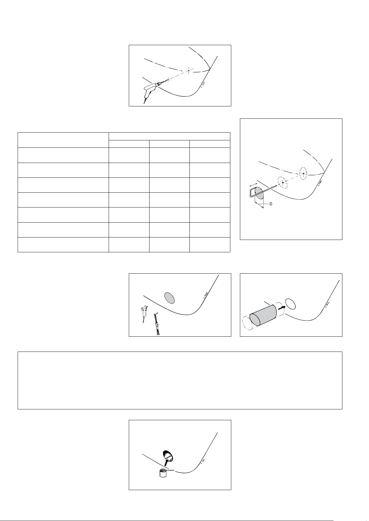
5 Installation of the thrust tunnel
Drill 2 holes into the ship’s hull, where the
centreline of the thrust tunnel will be, in accordance with the diameter of the marking
tool.
Pass the marking tool (home-made) through both pre-drilled holes and set out the outside
diameter of the thrust-tunnel to the hull.
Thruster
‘BOW . . . . .’
25 . . .
45 . . .
35 . . . 55 . . .
60 . . . 75 . . . 95 . . .
125 . . . 160 . . .
220 . . . 230 . . . 285 . . . 310 . . .
410 . . . 550 . . .
Steel GRP Aluminium
121
49
/64”)
(4
134
9
/32”)
(5
159
17
/64”)
(6
194
41
/64”)
(7
267
33
/64”)
(10
320
19
/32”)
(12
420
17
/32”)
(16
D [mm] (inches)
120
(4 13/32”)
136
(5 23/64”)
161
(6 11/32”)
196
(7 23/32”)
265
(10 7/16”)
320
(12 19/32”)
424
(16 11/16”)
120
(4 13/32”)
—
160
(6 19/64”)
196
(7 23/32”)
264
(10 25/64”)
320
(12 19/32”)
—
Dependent on the vessel’s construction material, cut out the holes by means of a jigsaw
or an oxy-acetylene cutter.
Install the thrust-tunnel.
Polyester thrust tunnel:
Resin: The resin used for the polyester thrust tunnel is Isophtalic
polyester resin (Norpol Pl 2857).
Pre-treatment: The outside of the tunnel must be roughened. Remove all of the top surface down to the glass-bre. Use a grinding
disc for this.
A polyester thrust tunnel should be nished
as follows:
• Roughen the hardened resin/glass-bre.
Apply a top coat of resin.
Important: Treat the end of the tunnel, after it has been sawn to
length, treat the end of the tube with resin. This will prevent water
seeping in.
Laminating: Apply a coat of resin as the rst coat. Lay on a glassbre mat and impregnate with resin. Repeat this procedure until
you have built up a sucient number of layers.
• Treat the side of the tunnel which comes
into contact with water with ‘epoxy paint’
or 2-component polyurethane paint.
• Then apply anti-fouling treatment if required.
16 020571.03
vetus® Installation recommendations for thrusters
Page 8
020536.05 iii
FOKKERSTRAAT 571 - 3125 BD SCHIEDAM - HOLLAND - TEL.: +31 10 4377700
E-MAIL: [email protected] - INTERNET: http://www.vetus.com
vetus
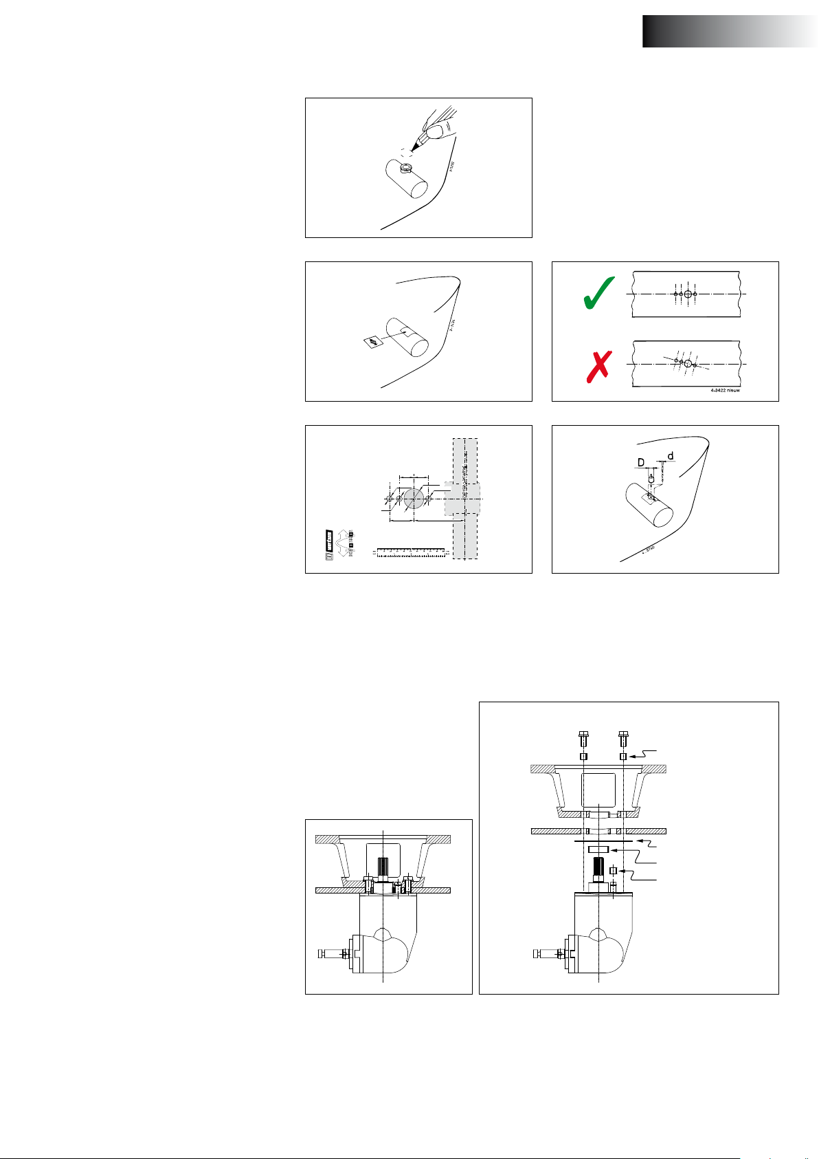
6 Drilling the holes in the thrust-tunnel
Mark the installation position of the bow
thruster by means of the intermediate
ange.
Use the drill pattern supplied, to determine
the correct position of the holes to be drilled.
Important: The pattern of the holes must be
positioned precisely on the centerline of the
tunnel.
ENGLISH
Consult the template for the dimensions of
the holes to be drilled.
Drill the holes through the thrust tunnel and
take care that the holes are free of burrs.
BOW7512D
BOW7524D
75 kgf
ø 185 mm
Schaal 1:1
Scala 1:1
Scale 1:1
Skala 1:1
Skala 1:1
Escala 1:1
22 (7/8”) 22 (7/8”)
3
/8”)
ø 9 (
29
/64”) 77 (3
ø 30 (1
Målestokk 1:1
3
/16”)
ø 9 (
1
/32”)
Suhde 1:1
3
/8”)
Echelle 1:1
Maßstab 1:1
ø 9
3
(
/8”)
37 (1
7 Protection of the bow thruster against corrosion
To prevent corrosion problems, do not use copper based anti-fouling. Cathodic
protection is a ‘must’ for the protection of all metal parts under water.
In order to protect the bow thruster tailpiece against corrosion, the tailpiece is
supplied with a zinc anode.
2014-01
Printed in the Netherlands
b.v.
TELEFAX: +31 10 4372673 - 4621286 -
Insulation bush
Corrosion of a steel or aluminium thrust
tunnel can be reduced by ensuring that the
tail piece is completely insulated from the
thrust-tunnel.
NOTE: The gaskets supplied are already electrically insulated. However the bolts and the
shaft need to be tted with insulation material, for example nylon bushes.
vetus® Installation recommendations for thrusters
Gasket
Insulation bush
Insulation bush
020571.03 17
Page 9

8 The power supply
8.1 Choice of battery
The total battery capacity must be sucient for the size of the bow
thruster; see the table. We recommend Vetus maintenance free marine batteries; these can be supplied in the following sizes: 55 Ah,
70Ah, 90 Ah, 108 Ah, 120 Ah, 143 Ah, 165 Ah, 200 Ah and 225 Ah.
We also recommend that each bow thruster is powered by its own
separate battery or batteries. This allows the battery bank to be
placed as close as possible to the bow thruster; the main power cables can then be short thus preventing voltage losses caused by long
cables.
noTe
Be sure to only use ‘sealed’ batteries if the batteries are located in the same compartment as the bow thruster.
The Vetus ‘SMF’ and ‘AGM’ maintenance-free batteries are ideally
suited to this application.
Batteries that are not ‘sealed’ may produce small amounts of explosive gas during the charging cycle.
Sparks generated by the carbon brushes of the bow thruster
motor may ignite this explosive gas.
Always use batteries whose type and capacity are compatible for
their use.
8.3 Main Switch
A main switch must be included on the ‘positive cable’.
A Vetus battery switch is a very suitable choice. Consult the following
table for the correct type of battery switch.
Art. code Vetus Battery Main Switch
BOW . . . .
25
35 — — —
45 — — —
55
60 — —
75 — —
95
160 —
220 — — —
285 48 Volt : BATSW600 — —
Standard Thruster
12 Volt 24 Volt 12 Volt 24 Volt
— — —
BATSW250
BATSW250
BATSW600
BATSW600
‘Extended Runtime’
Thruster
— —
—
BATSW600125 —
—
cauTion
In extreme cases, for example when a battery with a capacity of
ve times or more than suggested is used, there is the danger
of causing permanent damage to one or more of the following
shaft connections:
- The connection between motor shaft and the tail piece input
shaft.
- The connection between the tail piece output shaft and the
propeller.
8.2 Main power cables (battery cables)
The minimum diameter must be sucient for the bow thruster in use
and the voltage drop must not be more than 10% of the voltage supplied, consult the table in your bow thruster installation and operating manual.
noTe
The maximum duration of engagement and the thrust, as
specied by the technical details in your bow thruster installation and operating manual, are based on the recommended
storage battery capacities and storage battery connection
cables.
BATSW250 BATSW600
The BATSW250 is also available with two poles, (Vetus art. code
BATSW250T).
Main switch with remote control
Instead of a storage battery main switch, a remotely controlled main
switch annex emergency stop can be installed.
This remotely controlled main switch is available for 12 or 24 Volt direct voltages.
Vetus art. code: BPMAIN12 respectively BPMAIN24.
NOTE:
When using a series-parallel switch, the main switch must be suitable
for the voltage onboard.
Use a 12 Volt main switch if a 24 Volt bow thruster has been connected in combination with a series-parallel switch to a 12 Volt onboard network.
If appreciably larger batteries in combination with very short
connection cables with appreciably larger diameter than
recommended are used then the thrust will increase. In such
cases the maximum operating time must be reduced in order
to prevent damage to the motor.
18 020571.03
vetus® Installation recommendations for thrusters
Page 10
ENGLISH
8.4 Fuse
In addition to the main switch, a fuse must be included in the ‘positive cable’.
The fuse prevents the bow thruster from overloading, as well as protecting the onboard network from short circuiting.
Consult the table in your bow thruster installation and operating
manual for the correct fuse.
We can also provide a fuse holder for all types of fuses. Vetus art.
code: ZEHC100.
8.5 Series-parallel switch
Bow and stern thrusters that are only available for 24 Volts*) can be
connected to a 12 Volt onboard network with the help of a seriesparallel switch.
By installing a series-parallel switch:
- the 2 (12 Volt) storage batteries will be engaged in series during
use, so that the 24 Volt bow thruster receives the necessary 24
Volts of power.
- the 2 (12 Volt) storage batteries will be engaged in parallel during
recharging, and can be coupled to the 12 Volt charging system.
Vetus can provide a series-parallel switch that is ready to be connected to the Vetus 24 Volt bow thruster. Vetus art. code: BPSPE.
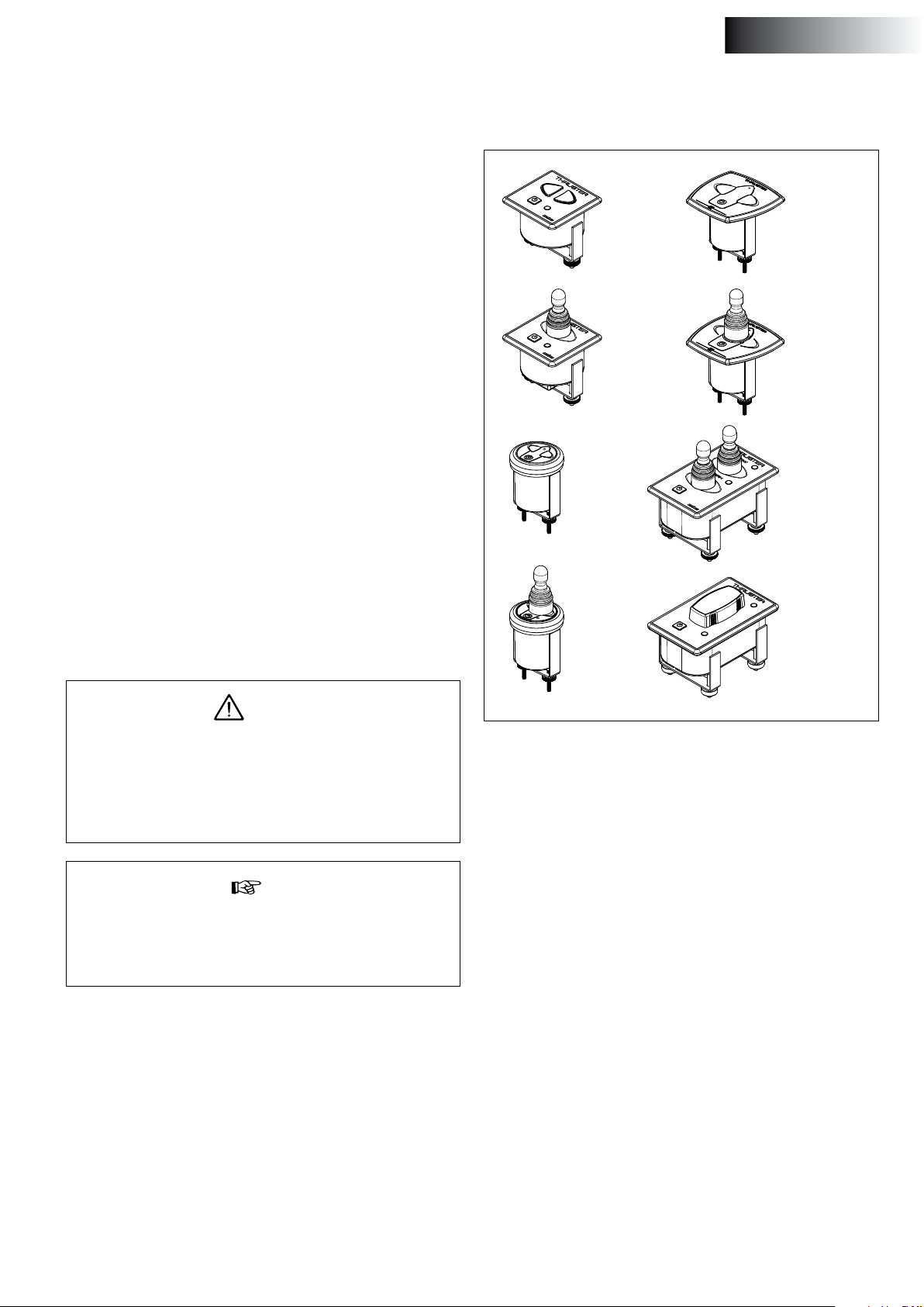
9 Bow thruster operation
Consult the Vetus catalogue for the various operating panels that are
available.
- BPSE2
- BPSSE
- BPJE2
- BPJSE
- BPSR
- BPAS
- BPAJ
- BPJDE2
- BPJDSE
If the battery that has been installed for the bow thruster will also be
powering other (12 Volt) systems, the following must be taken into
account:
Both batteries will be providing power to 12 Volt systems via the
charging current cables and charging current contacts of the seriesparallel switch.
Warning
A continuous stream of at most 100A may be carried through
the charging current contacts of the series-parallel switch, and
at most an intermittent current of 150A at 20% duration of engagement.
Never use these storage batteries as starting batteries and never
connect an anchor capstan to them.
Tip
If an isolating switch is included in the charging current cable,
the storage battery sets can be isolated, should they not be
charged for a long period of time, in order to prevent excessive
discharging.
- BPJR
- EZDOCK2
- EZDOCKS
9.1 Delay when reversing the turn direction
If a delay is desired where one of the following operating devices is
installed, a delay switch can be installed.
Operating device:
- BPJSTA, separate turn switch (Joystick),
- BPSM, operating panel for side mounting,
- FSxx, foot switch button
Delay: Vetus art. code: BPTD
The way in which the bow thruster is to be operated will remain unchanged after a series-parallel switch has been installed!
*) the Vetus bow thruster BOW28548 can be connected to a 24 Volt
onboard network with the help of the series-parallel switch supplied.
vetus® Installation recommendations for thrusters
020571.03 19
Page 11

vetus b.v.
Printed in the Netherlands
020571.04 2017-12
FOKKERSTRAAT 571 - 3125 BD SCHIEDAM - HOLLAND
TEL.: +31 0(0)88 4884700 - [email protected] - www.vetus.com
 Loading...