

Vetus BC12151, BC12252, BC12352, BC24122, BC24253 Operation Manual And Installation Instructions
...
Bedieningshandleiding en
installatie instructies
5
Operation manual and installation
instructions
Bedienungshandbuch und
I nstallationsvorschriften
Manuel d’utilisation et instructions
d’installation
Manual de uso e instrucciones de
instalación
Manuale d’uso e istruzioni per
l’installazione
9
13
17
21
25
Acculader
Battery charger
Batterieladegerät
Chargeur de batterie
Cargador de baterías
Caricabatterie
BC12151
BC12252
BC12352
BC24122
BC12503
BC12803
Copyright © 2017 Vetus b.v. Schiedam Holland
BC24253
BC24403
090141.01

Inhoud
Contents
Inhalt
1 Inleiding . . . . . . . . . . . . . . . . 5
1.1 Veiligheid . . . . . . . . . . . . . . . . 5
1.2 Algemeen . . . . . . . . . . . . . . . .5
2 Gebruikersinformatie. . . . . . . . 5
2.1 Doel van deze gebruiksaanwijzing 5
3 Voor uw eigen veiligheid . . . . . 5
3.1 Algemeen . . . . . . . . . . . . . . . .5
3.2 Toepassing . . . . . . . . . . . . . . . 5
4 Kenmerken . . . . . . . . . . . . . . 6
4.1 Toelichting op de laadkarakte-
ristiek . . . . . . . . . . . . . . . . 6
5 Installatie. . . . . . . . . . . . . . . . 6
5.1 Opstellen 6
5.2 Accu-aansluitingen. . . . . . . . . . 6
5.3 Scheidingsdiode . . . . . . . . . . . 7
5.4 Instellen laadspanning . . . . . . . 7
5.5 Temperatuursensor (BCTS) . . . . . 7
5.6 Afstandsbedieningspaneel (BCRP) 7
5.7 Aansluiten netspanning. . . . . . . 7
6 Bediening . . . . . . . . . . . . . . . 7
7 Storingen. . . . . . . . . . . . . . . . 7
1 Introduction. . . . . . . . . . . . . . 9
1.1 Safety . . . . . . . . . . . . . . . . 9
1.2 General . . . . . . . . . . . . . . . . 9
2 Users information . . . . . . . . . . 9
2.1 Aim of this manual . . . . . . . . . . 9
3 For your own safety . . . . . . . . . 9
3.1 General . . . . . . . . . . . . . . . . 9
3.2 Use . . . . . . . . . . . . . . . . 9
4 Features . . . . . . . . . . . . . . . 10
4.1 Explanation to the charging
characteristic. . . . . . . . . . . . . 10
5 Installation. . . . . . . . . . . . . . 10
5.1 Installing . . . . . . . . . . . . . . . 10
5.2 Battery connections . . . . . . . . 10
5.3 Diode splitter . . . . . . . . . . . . 11
5.4 Selecting charging voltage. . . . 11
5.5 Temperature sensor (BCTS). . . . 11
5.6 Remote control panel (BCRP) . . 11
5.7 Connection to mains voltage . . 11
6 Operation . . . . . . . . . . . . . . 11
7 Trouble shooting. . . . . . . . . . 11
1 Einleitung . . . . . . . . . . . . . . 13
1.1 Sicherheit 13
1.2 Allgemeines . . . . . . . . . . . . . 13
2 Benutzerinformationen . . . . . 13
2.1 Zweck dieser Bedienungsanleitung 13
3 Zu Ihrer eigenen Sicherheit . . . 13
3.1 Allgemeines . . . . . . . . . . . . . 13
3.2 Anwendung . . . . . . . . . . . . . 13
4 Merkmale . . . . . . . . . . . . . . 14
4.1 Erklärung Ladekennwerte . . . . 14
5 Installation. . . . . . . . . . . . . . 14
5.1 Aufstellen 14
5.2 Batterieanschlüsse . . . . . . . . . 14
5.3 Trenndiode. . . . . . . . . . . . . . 15
5.4 Einstellen der Ladespannung . . 15
5.5 Temperatursensor (BCTS) . . . . . 15
5.6 Fernbedienungspaneel (BCRP) . 15
5.7 Anschluss Netzspannung. . . . . 15
6 Bedienung . . . . . . . . . . . . . . 15
7 Störungen . . . . . . . . . . . . . . 15
8 De ventilatorsnelheid. . . . . . . . 8
9 Technische gegevens . . . . . . . . 8
10 Draadkeuzetabel. . . . . . . . . . 29
11 Acculaderkeuze. . . . . . . . . . . 29
12 Aansluittekeningen . . . . . . . . 30
13 Elektrische schema’s . . . . . . . 32
14 Instellingen en informatie. . . . 36
14.1 Accu laadcurve . . . . . . . . . . . 36
14.2 Laadstatusindicatie. . . . . . . . . 38
14.3 S1 (DIP Switch) instellingen . . . 38
14.4 Aanbevolen instellingen . . . . . 38
14.5 Standaard instellingen. . . . . . . 40
14.6 Storingsindicatie . . . . . . . . . . 40
14.7 CN2 Alarmen en ventilator . . . . 42
14.8 Slaap Mode. . . . . . . . . . . . . . 42
14.9 Pen bezetting CN3, Temperatuur sensor & Afstandsbediening 42
14.10 Pen bezetting ESB aansluiting . . 43
14.11 Pen bezetting CN4,
Afstandsbediening . . . . . . . . . 43
14.12 Temperatuursensor (BCTS) . . . . 44
14.13 Afstandsbedieningspaneel (BCRP) 44
14.14 Reddings-acculaadcurve . . . . . 44
14.15 Temperatuurcompensatie . . . . 45
8 Fan speed . . . . . . . . . . . . . . 12
9 Technical data. . . . . . . . . . . . 12
10 Wire size selection table. . . . . . 29
11 Battery charger selection . . . . . 29
12 Connection drawings . . . . . . . 30
13 Electrical circuit diagrams . . . . 32
14 Settings and information . . . . . 36
14.1 Battery Charging Curve . . . . . . 36
14.2 Charging status indication . . . . 38
14.3 S1 (DIP Swich) Settings . . . . . . 38
14.4 Recommended settings. . . . . . 38
14.5 Default settings . . . . . . . . . . . 40
14.6 Fault indication . . . . . . . . . . . 40
14.7 CN2 Alarms ans Fan control . . . 42
14.8 Sleep Mode. . . . . . . . . . . . . . 42
14.9 Pin assigment of CN3, Temperatuur sensor & Remote control . 42
14.10 Pin assigment ESB connector . . 43
14.11 Pin assigment of CN4, Remote
control . . . . . . . . . . . . . . . 43
14.12 Temperature sensor . . . . . . . . 44
14.13 Remote control panel . . . . . . . 44
14.14 Rescue Battery Curve . . . . . . . 44
14.15 Temperature compensation . . . 45
8 Lüftergeschwindigkeit . . . . . . 16
9 Technische Eigenschaften . . . . 16
10 Drahtwahltafel . . . . . . . . . . . 29
11 Auswahl des Batterieladegeräts. 29
12 Anschlusszeichnungen . . . . . . 30
13 Elektrische schema’s . . . . . . . 32
14 Einstellungen und Informationen 36
14.1 Akkuladekennlinie . . . . . . . . . 36
14.2 Ladestatusanzeige . . . . . . . . . 38
14.3 S1 (DIP-Schalter)-Einstellungen . 38
14.4 Empfohlene Einstellungen . . . . 38
14.5 Standardeinstellungen . . . . . . 40
14.6 Störungsanzeige . . . . . . . . . . 40
14.7 CN2 Alarme und Lüfter . . . . . . 42
14.8 Schlafmodus . . . . . . . . . . . . . 42
14.9 Pinbelegung CN3, Temperatursensor und Fernbedienung. . 42
14.10 Pinbelegung ESB-Anschluss . . . 43
14.11 Pinbelegung CN4, Fernbedienung 43
14.12 Temperatursensor . . . . . . . . . 44
14.13 Fernbedienungspaneel . . . . . . 44
14.14 Akkuladekennlinie Rettungs-
funktion . . . . . . . . . . . . . . . 44
14.15 Temperaturausgleich . . . . . . . 45
15 Hoofdafmetingen . . . . . . . . . 46
2 090141.01
15 Principal dimensions . . . . . . . . 46
vetus® Battery chargers BC12151, BC12252, BC12352, BC12503, BC12803, BC24122, BC24253, BC24403
15 Hauptabmessungen . . . . . . . . 46

Table des matières
Contenido
Sommario
1 Introduction. . . . . . . . . . . . . 17
1.1 Sécurité . . . . . . . . . . . . . . . 17
1.2 Généralités . . . . . . . . . . . . . . 17
2 Informations pour l’utilisateur . 17
2.1 Objectif de ce mode d’emploi . . 17
3 Pour votre propre sécurité . . . 17
3.1 Généralités . . . . . . . . . . . . . . 17
3.2 Application . . . . . . . . . . . . . . 17
4 Caractéristiques . . . . . . . . . . 18
4.1 Explications concernant la
caractéristique de charge. . . . . 18
5 Installation. . . . . . . . . . . . . . 18
5.1 Réglage . . . . . . . . . . . . . . . 18
5.2 Branchements des batteries . . . 18
5.3 Diode de séparation . . . . . . . . 19
5.4 Réglage de la tension de charge 19
5.5 Capteur de température (BCTS) . 19
5.6 Panneau de commande à
distance (BCRP) . . . . . . . . . . . 19
5.7 Raccordement au courant . . . . 19
6 Fonctionnement . . . . . . . . . . 19
7 Pannes . . . . . . . . . . . . . . . . 19
8 Vitesse du ventilateur. . . . . . . 20
9 Spécications techniques . . . . 20
10 Tableau de selection de ls. . . . 29
11 Choix du chargeur de batterie. . 29
12 Schémas de raccordement . . . . 31
13 Schémas électriques . . . . . . . . 33
14 Réglages et informations . . . . . 37
14.1 Courbe de charge de la batterie. 36
14.2 Indication de l’état de charge . . 38
14.3 Réglages (DIP Switch) S1 . . . . . 38
14.4 Réglages recommandés. . . . . . 38
14.5 Réglages standard . . . . . . . . . 40
14.6 Indication de panne . . . . . . . . 40
14.7 CN2 Alarmes et ventilateur. . . . 42
14.8 Mode Veille . . . . . . . . . . . . . . 42
14.9 Aectation de borne CN3,
Capteur de température &
Télécommande . . . . . . . . . . . 42
14.10 Aectation de borne con-
nexion ESB . . . . . . . . . . . . . . 43
14.11 Aectation de borne CN4,
Télécommande . . . . . . . . . . . 43
14.12 Capteur de température . . . . . 44
14.13 Panneau de télécommande . . . 44
14.14 Courbe de charge sauvetage
de batterie . . . . . . . . . . . . . . 44
14.15 Compensation de température . 45
15 Dimensions principales . . . . . . 46
1 Introducción. . . . . . . . . . . . . 21
1.1 Seguridad . . . . . . . . . . . . . . . 21
1.2 Generalidades . . . . . . . . . . . . 21
2 Información al usuario . . . . . . 21
2.1 Propósito de este manual. . . . . 21
3 Por su propia seguridad . . . . . 21
3.1 En General . . . . . . . . . . . . . . 21
3.2 Uso . . . . . . . . . . . . . . . 21
4 Características . . . . . . . . . . . 22
4.1 Explicación del patrón de carga. 22
5 Instalación . . . . . . . . . . . . . . 22
5.1 Instalando . . . . . . . . . . . . . . . 22
5.2 Conexiones de la batería . . . . . 22
5.3 Diodo de separación . . . . . . . 23
5.4 Ajustar la tensión de carga . . . . 23
5.5 Sensor de Temperatura (BCTS). . 23
5.6 Panel de control remoto (BCRP) . 23
5.7 Conexión al voltaje de la red
eléctrica . . . . . . . . . . . . . . . 23
6 Manejo . . . . . . . . . . . . . . . . 23
7 Averías . . . . . . . . . . . . . . . . 23
8 La velocidad del ventilador . . . 24
9 Especicaciones técnicas . . . . 24
10 Tabla de selección de hilos . . . . 29
11 Elección de cargador de baterías 29
12 Esquemas de conexiones . . . . . 31
13 Diagramas de los circuitos
eléctricos . . . . . . . . . . . . . . . 33
14 Ajustes e información . . . . . . . 37
14.1 Curva de carga de la batería . . . 36
14.2 Indicación del estado de carga . 38
14.3 Ajustes del S1 (conmutador DIP) 38
14.4 Ajustes recomendados . . . . . . 38
14.5 Ajustes estándar . . . . . . . . . . 40
14.6 Indicación de avería . . . . . . . . 40
14.7 CN2 Alarmas y ventilador . . . . . 42
14.8 Modo de hibernación . . . . . . . 42
14.9 Esquema de pines CN3, sensor de temperatura y control
remoto . . . . . . . . . . . . . . . 42
14.10 Esquema de pines conexión ESB 43
14.11 Esquema de pines CN4, con-
trol remoto . . . . . . . . . . . . . . 43
14.12 Sensor de Temperatura . . . . . . 44
14.13 Panel de control remoto . . . . . 44
14.14 Curva de carga salva batería . . . 44
14.15 Compensación de temperatura . 45
15 Dimensiones principales . . . . . 46
1 Introduzione . . . . . . . . . . . . 25
1.1 Sicurezza . . . . . . . . . . . . . . . 25
1.2 Generale . . . . . . . . . . . . . . . 25
2 Informazioni. . . . . . . . . . . . . 25
2.1 Scopo di questo manuale. . . . . 25
3 Sicurezza personale . . . . . . . . 25
3.1 Generale . . . . . . . . . . . . . . . 25
3.2 Utilizzo . . . . . . . . . . . . . . . 25
4 Caratteristiche . . . . . . . . . . . 26
4.1 Informazioni relative alle
caratteristiche di carica . . . . . . 26
5 Installazione. . . . . . . . . . . . . 26
5.1 Collocazione . . . . . . . . . . . . . 26
5.2 Collegamenti delle batterie . . . 26
5.3 Diodo di separazione . . . . . . . 27
5.4 Impostazione della tensione
di carica . . . . . . . . . . . . . . . 27
5.5 Sensore temperatura (BCTS) . . . 27
5.6 Pannello di controllo remoto
(BCRP) . . . . . . . . . . . . . . . 27
5.7 Collegamento alla rete di
fornitura d’energia elettrica . . . 27
6 Uso . . . . . . . . . . . . . . . . . . . 27
7 Guasti . . . . . . . . . . . . . . . . . 27
8 Velocità del ventilatore. . . . . . 28
9 Dati tecnici. . . . . . . . . . . . . . 28
10 Tabella di selezione dei cavi . . . 29
11 Scelta del caricabatterie. . . . . . 29
12 Graci dei collegamenti . . . . . . 31
13 Diagrammi dei circuiti elettrici . 33
14 Impostazioni ed informazioni . . 37
14.1 Curva di carica della batteria. . . 36
14.2 Indicazione dello stato di carica. 38
14.3 Impostazioni S1 (DIP Switch). . . 38
14.4 Impostazioni consigliate . . . . . 38
14.5 Impostazioni standard. . . . . . . 40
14.6 Indicazione di malfunzionamento 40
14.7 CN2 Allarmi e ventilatore . . . . . 42
14.8 Modalità Sleep. . . . . . . . . . . . 42
14.9 Pin CN3, Sensore di tempera-
tura e Telecomando . . . . . . . . 42
14.10 Pin ESB Connettore. . . . . . . . . 43
14.11 Pin CN4, Telecomando. . . . . . . 43
14.12 Sensore temperatura . . . . . . . 44
14.13 Pannello di comando a distanza 44
14.14 Curva di carico di sicurezza. . . . 44
14.15 Compensazione della tempe-
ratura . . . . . . . . . . . . . . . 45
15 Dimensioni principali . . . . . . . 46
vetus® Battery chargers BC12151, BC12252, BC12352, BC12503, BC12803, BC24122, BC24253, BC24403
090141.01 3

Dit produkt voldoet aan de vereisten van EG-richtlijnen 2004/108/EC
(EMC).
This product conforms to the EEC Directive requirements 2004/108/
EC (EMC)
Dieses Produkt erfüllt die Anforderungen der folgenden EU-Richtlinien 2004/108/EC (EMC)
Ce produit répond aux normes de la directive CE 2004/108/EC (EMC)
Este producto cumple las normas de la directiva CE 2004/108/EC
(EMC)
Questo prodotto è conforme alle direttive comunitarie 2004/108/EC
(EMC)
EN 55014-1:2006 +A2:2011, EN 55022:2010 class B, EN 61204-3:2000,
EN 61000-6-3:2007+A1:2011, EN 61000-3-2:2006+A2:2009 class A,
EN61000-3-3:2008 (Emission)
EN 55017-2:1997+A2:2008, EN 55024:2010, EN 61204-3:2000,
EN 1000-6-1:2007, ENV 50204:1995 (Immunity)
4 090141.01
vetus® Battery chargers BC12151, BC12252, BC12352, BC12503, BC12803, BC24122, BC24253, BC24403

NEDERLANDS
1 Inleiding
1.1 Veiligheid
Waarschuwingsaanduidingen
In deze handleiding worden in verband met veiligheid de volgende
waarschuwingsaanduidingen gebruikt:
Gevaar
Geeft aan dat er een groot potentieel gevaar aanwezig is dat ernstig
letsel of de dood tot gevolg kan hebben.
WaarschuWinG
Is een opmerking die u erop wijst dat de acculader beschadigd zou
kunnen worden.
Let op
Legt de nadruk op belangrijke procedures, omstandigheden, enzovoort.
tip
Is een opmerking die het werken met de acculader vergemakkelijkt
als u deze tip in acht neemt!
Symbolen
2 Gebruikersinformatie
2.1 Doel van deze gebruiksaanwijzing
Deze gebruiksaanwijzing geeft belangrijke informatie nodig voor het
veilig en correct gebruiken van de acculader. Neem daarom de aanwijzingen in acht om gevaar voor de gebruiker te voorkomen!
Lees de gebruiksaanwijzing aandachtig door en neem alle hierin vermelde informatie in acht om de betrouwbaarheid van de installatie
te verhogen en de levensduur van de acculader te verlengen.
Laat deze gebruiksaanwijzing door iedereen lezen welke met het gebruik van de acculader belast is.
Voordat de acculader voor de eerste keer ingeschakeld wordt, moeten alle hoofdstukken van deze gebruiksaanwijzing aandachtig gelezen worden.
3 Voor uw eigen veiligheid
3.1 Algemeen
Gevaar
In de acculader treden levensgevaarlijke spanningen op!
Het laadapparaat mag alleen door een elektricien geopend en gerepareerd worden.
Alvorens de acculader te openen moeten altijd de aansluitingen met
de netspanning en met de accu losgenomen worden.
Geeft aan dat de betreende handeling moet worden uitge-
voerd.
Geeft aan dat een bepaalde handeling verboden is.
Geef de veiligheidsaanwijzingen door aan andere personen die de
acculader bedienen.
Algemene regels en wetten met betrekking tot veiligheid en ter voorkoming van ongelukken dienen altijd in acht te worden genomen.
1.2 Algemeen
De VETUS volautomatische acculader is zeer geschikt voor het snel
en eciënt laden van vele soorten lood/zuuraccu’s (zowel open als
gesloten vloeistofgevulde accu’s, gelgevulde accu’s, semi-tractie accu’s of AGM accu’s geladen worden).
Raadpleeg de technische gegevens voor de maximale laadstroom.
Doordat de laadstroom volautomatisch wordt geregeld volgens een
optimale laadkarakteristiek kan de lader altijd aangesloten blijven;
ook tijdens de winterberging.
De acculader is voorzien van meerdere uitgangen om gelijktijdig 2 of
3 accu’s gescheiden te kunnen laden (type BC12151 heeft 1 uitgang!)
De acculader is geschikt voor een netspanning van zowel 115 als 230
Volt wisselspanning.
Let op
Worden tijdens het gebruik van de acculader veiligheidsvoorschriften niet in acht genomen, dan vervalt elke vorm van garantie en aansprakelijkheid van de fabrikant/leverancier.
3.2 Toepassing
De acculader is uitsluitend bestemd voor het laden van lood/zuuraccu’s.
Er kunnen, afhankelijk van de instelling open of gesloten vloeistofgevulde accu’s, gelgevulde accu’s, semi-tractie accu’s of AGM accu’s
geladen worden.
Neem a.u.b. de voorschriften van de fabrikant van de accu in acht!
Voor alle andere accu’s en niet oplaadbare accu’s is de acculader
niet geschikt!
De acculader mag alleen in technisch perfecte toestand worden gebruikt. Als voor de veiligheid van gebruiker en schip relevante storingen optreden, moet de acculader direct buiten werking worden
gezet.
Wijzigingen aan het apparaat zijn om veiligheidsredenen verboden.
Reparaties (bv. vervangen van de gelijkstroom zekering) mogen alleen door ter zake kundige personen worden uitgevoerd.
Veiligheidsaarding moet in acht worden genomen!
Zorg er voor dat de eigenaar van het schip over deze handleiding kan beschikken.
vetus® Battery chargers BC12151, BC12252, BC12352, BC12503, BC12803, BC24122, BC24253, BC24403
090141.01 5

4 Kenmerken
5 Installatie
- Geschikt voor alle gangbare wisselspanningen en voorzien van
cos phi correctie.
- Geschikt voor loodzuur, gel en AGM accu’s.
- Ondersteuning afstandsbediening BCRP als optionele accessoire.
- Spanning / temperatuur compensatie met optionele temperatuursensor.
- 2 fasen ventilatorsnelheid (slaapstand).
- Uitgangsvermogen OK signaal.
- Uitgang alarmsignaal.
- Hoog rendement en hoge betrouwbaarheid.
- Geïntegreerde accu-redding functie.
- Voorzien van Extra Start Accu (ESB) uitgang functie
- Bescherming tegen kortsluiting / te hoge spanning / te hoge temperatuur / netspanningsdip (Brown-out).
- Weerstaat 2G triltest.
De VETUS acculader heeft een laadkarakteristiek zoals die is afgebeeld in 14.1 pag. 36.
4.1 Toelichting op de laadkarakteristiek
1 Bulk Fase (CC, Constant Current)
Aan het begin van het laadproces wordt de lege accu opgeladen met
een constante stroom (maximum laadstroom) totdat de accuspanning de ingestelde laadspanning (Zie 14.3 S1-Instellingen) heeft bereikt.
2 Absorptie Fase(CV, Constant Voltage)
De tijdsduur van het absorptie laden is afhankelijk is van de toestand
van de accu.
De lader wacht 2 minuten alvorens naar de absorptie fase te gaan,
daarna wordt met constante spanning geladen tot de accu volledig
is opgeladen.
Zodra de batterij volledig is opgeladen of de laadstroom, gedurende
15 minuten, lager is dan 6,25% van de nominale laadstroom wordt de
absorptie fase beëindigd.
5.1 Opstellen
Kies een droge plaats op geruime afstand van een warmtebron.
Hoge temperaturen kunnen het vermogen van het apparaat negatief beïnvloeden.
Dek daarom de ventilatieopeningen nooit af en houdt rondom de
acculader een vrije ruimte van tenminste 10 cm.
Plaats de acculader niet te ver van de accu om het spanningsverlies
over de (12 Volt resp. 24 Volt) aansluitdraden zoveel mogelijk te beperken. Beter is het dus om de 230 Volt leiding indien nodig lang te
maken.
WaarschuWinG
Plaats de acculader ook niet pal boven de accu; zwavelhoudende accudampen kunnen schade aan de elektronische onderdelen veroorzaken.
Het apparaat voldoet aan de beschermingsgraad IP 20.
Monteer de acculader in verticale positie met de aansluitingen naar
onder tegen een wand, zie ook ’15 Hoofdafmetingen’.
Let op
Boor geen extra bevestigingsgaten in de metalen behuizing!
De aanwezigheid van kleine metaaldeeltjes in de acculader kan
onherstelbare schade veroorzaken.
5.2 Accu-aansluitingen
WaarschuWinG
Neem eerst de netaansluiting los alvorens de accu’s aan te sluiten of
los te nemen.
Let op
De accuspanning moet overeenstemmen met de gegevens vermeld
op de acculader!
Raadpleeg de ’13 Elektrische schema’s’ hoe de acculader op de accu’s
aan te sluiten.
Pas kabels van voldoende dikte toe en gebruik kabelschoenen, zie
‘10 Draadkeuzetabel’ voor de juiste draaddoorsnede.
3 Float Fase
Na de absorptie fase, schakelt de acculader over naar de oat fase,
waarbij de accu 100% lading behoudt zonder te worden overladen
of te worden beschadigd. Daarom kan de lader continu verbonden
blijven met de accu.
4 Re-conditionering Fase
Elke 12 dagen, schakelt de acculader, gedurende 85 minuten, terug
naar Bulk Fase om de accu nieuw leven in te blazen. Dit voorkomt
vermoeidheidsverschijnselen zoals sulfatering.
6 090141.01
vetus® Battery chargers BC12151, BC12252, BC12352, BC12503, BC12803, BC24122, BC24253, BC24403
tip
Om aan de CE richtlijnen te voldoen verdient het aanbeveling om
korte afgeschermde of getwiste accukabels te gebruiken.
WaarschuWinG
Grote stromen door te dunne draden of overgangsweerstanden veroorzaakt door slechte verbindingen kunnen er toe leiden dat draden
of (stekker)verbindingen zeer heet worden en brand kunnen veroorzaken.
Let op
Let bij het aansluiten van de lader op de accu op de juiste polariteit!

NEDERLANDS
Sluit altijd eerst de plus (+) kabel(s) aan en als laatste de min (- )
kabel.
5.3 Scheidingsdiode
De acculader is voorzien van een scheidingsdiode zodat meerdere accu’s gescheiden kunnen worden geladen (behalve model BC12151).
Voor het gescheiden laden van de accu’s door de dynamo moet een
aparte scheidingsdiode worden geïnstalleerd. Pas de Vetus spanningsverliesvrije scheidingsdiode toe of zorg er voor dat de laadspanning van de dynamo gecompenseerd wordt.
5.4 Instellen laadspanning
Stel de laadspanning van de acculader in voor het type lood/zuur
accu dat moet worden geladen. Zie tabel 14.4 op pagina 38.
5.5 Temperatuursensor (BCTS)
Indien in tropische gebieden, of door andere omstandigheden de
accu’s zeer warm worden, verdient het aanbeveling om voor deze
(hoge) accutemperatuur de laadkarakteristiek aan te passen. Dit kan
door middel van de als optie door VETUS te leveren temperatuursensor.
Raadpleeg ‘14.12 Temperatuursensor’ voor het aansluiten van de optionele temperatuursensor.
De 6 polige RJ aansluiting (TEMP/CN3) is bestemd voor het aansluiten van de temperatuursensor.
Plaats de temperatuursensor op de accu welke de hoogste temperatuur zal bereiken.
5.6 Afstandsbedieningspaneel (BCRP)
Raadpleeg ‘14.13 Afstandsbedieningpaneel’ voor het aansluiten van
een optioneel afstandsbedieningspaneel.
De 6 polige RJ aansluiting (CN4) is bestemd voor het aansluiten van
het afstandsbedieningspaneel.
5.7 Aansluiten netspanning
De acculader is geschikt voor een netspanning van zowel 115 als 230
Volt wisselspanning.
Om aan de CE richtlijnen te voldoen verdient het aanbeveling de acculader te aarden.
WaarschuWinG
Het aarden van 230 Volt electrische apparaten aan boord van een
schip dat niet via een walaansluiting verbonden is met een tegen
aardlek beveiligd walstopcontact is alleen zinvol als er op het schip
een aardlekbeveiliging of gestel-isolatiebeveiligings-installatie aanwezig is (zwevend net).
Raadpleeg hiervoor uw installateur.
Tevens zijn hier de locale voorschriften van belang die per land verschillen en ook de toepassing kan daarbij van belang zijn (voor beroepsvaart en in het bijzonder passagierschepen gelden vaak speciale regels).
VETUS kan geen verantwoordelijkheid aanvaarden voor het toepassen van de acculader in strijd met de plaatselijke voorschriften.
6 Bediening
Na het aansluiten van de accu wordt het laden automatisch gestart
en zal de ‘STATUS’ LED gaan branden om dit aan te geven.
7 Storingen
Storing / LED indicatie Mogelijke oorzaak Oplossing
Rood, knippert langzaam.
Rood, knippert snel.
Rood, continu aan
Rood, knippert dubbel. Ventilator storing. Controleer de ventilator op vervuiling of schade.
Rood, knippert langzaam,
elke 2 sec.
Accuspanning te laag of accu
overladen.
Defecte accu. Vervang de accu.
Accu of acculader heeft te
hoge temperatuur.
Kortsluiting of verkeerd om
aangesloten (+ en - verwisseld.
Storing bij de Extra Tweede
Accu.
Controleer de accu.
Schakel de acculader uit en weer aan.
Verbeter de ventilatie van de accu of de acculader.
Zorg eer voor dat geen van de ventilatieopeningen bedekt zijn.
Indien mogelijk zorg voor een lagere omgevingstemperatuur.
Sluit de acculader met de juiste polariteit aan.
Verhelp de kortsluiting.
Controleer of de zekering defect is en vervang indien noodzakelijk.
Controleer de extra accuaansluiting op kortsluiting.
vetus® Battery chargers BC12151, BC12252, BC12352, BC12503, BC12803, BC24122, BC24253, BC24403
090141.01 7

8 De ventilatorsnelheid
De snelheid van de ventilator wordt bepaald door de belasting en de
temperatuur van het koellichaam.
1 Ventilatorsnelheid 100%:
- Bij een belasting ≥ 75%
- Bij een belasting ≥ 50% en een temperatuur van het koellichaam
≥50 ºC
- Indien het koellichaam een temperatuur heeft van ≥75 ºC
2 Ventilatorsnelheid 50%:
- Bij een temperatuur van het koellichaam ≥67,5ºC
3 Ventilatorsnelheid 0%:
- Bij een belasting <75%
- Bij een koellichaam temperatuur van <35 ºC
9 Technische gegevens
Type: BC12151 BC12252 BC12352 BC12503 BC12803 BC24122 BC24253 BC24403
Voedingsspanning 90 - 264 V AC
Frequentiebereik 47 - 63 Hz
Cos phi (typisch) > 0,92 bij volle belasting
Rendement (typisch) bij 230 V AC 87 % 87 % 87 % 87 % 87 % 90% 90% 90%
Opgenomen vermogen, maximaal 250 W 400 W 550 W 800 W 1300 W 400 W 800 W 1250 W
Accuspanning, nominaal 12 V 24 V
Laadspanning Boost
Laadspanning Float
Laadstroom, nominaal 15 A 25 A 35 A 50 A 80 A 12 A 25 A 40 A
Aantal geïsoleerde uitgangen 1 2 2 3 3 2 3 3
Laadkarakteristiek: IUoU, Begrensde laadstroom, laadspanning (equalize), onderhoudsspanning (oat)
ESB uitgang 1 1 1 -- -- -- -- -ESB uitgang spanning / stroom 13,8 V / 2 A -- -- -- -- -Beveiligingen,
Te hoge accuspanning
Te hoge temperatuur Acculader heeft een temperatuur hoger dan 100 °C ± 5 °C, gemeten aan het koelproel
Extra functies,
Alarmsignaal Maak en breek contact van relais (zie 14.7 CN2 Alarmen en ventilator)
Temperatuur compensatie -10 mV / 0,5 °C met temperatuursensor
Slaap mode Door middel van afstandsbediening en S1-4 DIP switch (zie 14.3)
Omgevingstemperatuur tijdens gebruik: - 10 °C tot +50 °C, tijdens opslag: - 20 °C tot +70 °C
Relatieve vochtigheid 20 tot 90 % condensvrij
Temperatuurcoëcient ± 0,03 % ( 0 -50 °C)
Vibratie 10 - 500 Hz, 2G 10 min. / 1 periode van 60 min elk langs de X, Y en Z as
Beschermingsgraad IP20
Afmetingen [mm]: 205 x 84 x 259
Gewicht [kg] 1,6 1,7 1,9 3,1 4,0 1,6 2,9 3,9
beveiliging door uitschakelen uitgang (herstel na uit- en weer inschakelen netspanning)
(In te stellen met S1 DIP switch)
(In te stellen met S1 DIP switch)
Automatisch herstel als de temperatuur van het koelproel gedaald is tot 50 ±5 °C
14,4 V / 14,7 V
(In te stellen met S1 DIP switch)
13,8 V / 13,5 V
(In te stellen met S1 DIP switch)
> 17,5 V ± 1 % > 35 V ± 1 %
52 ±5 °C (Optionele temperatuur sensor)
-20 mV / 0,5 °C met temperatuursen-
205 x 84 x
279
237 x 90 x
288
237 x 90 x
328
205 x 84 x
259
28,8 V / 29,4 V
27,6 V / 27,0 V
sor
237 x 90 x
288
237 x 90 x
328
8 090141.01
vetus® Battery chargers BC12151, BC12252, BC12352, BC12503, BC12803, BC24122, BC24253, BC24403

ENGLISH
1 Introduction
1.1 Safety
Warning indications
The following warning indications are used in this manual in the context of safety:
DanGer
Indicates that great potential danger exists that can lead to serious
injury or death.
WarninG
Is a comment that indicates that the battery charger could be damaged.
note
Emphasises important procedures, circumstances etc.
tip
Is a comment that simplies working with the battery charger if you
observe this tip!
2 Users information
2.1 Aim of this manual
This user’s manual provides important information, necessary for
safe and correct use of the battery charger. Therefore observe the
instructions to prevent danger to the user!
Read the manual through carefully and observe all information stated herein to increase the reliability of the installation and to extend
the life span of the battery charger.
Let everyone who is going to use the battery charger read through
this manual.
Before the battery charger is switched on for the rst time, all chapters of this manual must have been read through carefully.
3 For your own safety
3.1 General
DanGer
Highly dangerous currents can arise in the battery charger!
The charger may only be opened and repaired by an electrician.
Before opening the battery charger, always disconnect it from the
mains voltage and the battery.
Symbols
Indicates that the relevant procedure must be carried out.
Indicates that a particular action is forbidden.
Pass the safety precautions on to other people who will use the battery charger.
General rules and laws concerning safety and accident prevention
must always be observed.
1.2 General
The VETUS fully automatic battery charger is extremely suitable for
fast and ecient charging of many kinds of lead/acid batteries (both
open and sealed uid lled batteries, gel lled batteries, deep cycle
batteries and AGM batteries).
Refer to the technical details for the maximum charging current. Because the charging current is fully automatically regulated according
to an optimum charging type, the charger can always stay connected; even during winter storage.
The battery charger has multiple outputs, to charge 2 or 3 separate
batteries at the same time (type BC12151 has 1 outputs!).
The battery charger is made for mains voltages of both 115 and 230
volts AC current.
note
If the safety precautions are not observed during use of the battery
charger, then all forms of guarantee and liability of the manufacturer/supplier will lapse.
3.2 Use
The battery charger is exclusively designed for charging lead/acid
batteries. Depending on the setting, open or sealed uid lled batteries, gel lled batteries, deep cycle batteries or AGM batteries can
be charged.
Please observe the following instructions from the manufacturer.
The battery charger is not suitable for all other batteries and nonchargeable batteries!
The battery charger may only be used in technically perfect condition. If malfunctions occur that can aect the safety of user and ship,
the battery charger must immediately be turned o.
For safety reasons, amendments to the apparatus are prohibited.
Repairs (e.g. replacing the direct current fuse) may only be carried
out by persons skilled in such.
Safety earthing must be observed.
Make sure that the user of the vessel is supplied with the owner’s manual.
vetus® Battery chargers BC12151, BC12252, BC12352, BC12503, BC12803, BC24122, BC24253, BC24403
090141.01 9

4 Features
5 Installation
- Universal AC input with active Power Factor Correction.
- Compatible with Lead Acid, Gel and AGM batteries.
- Support remote controller BCRP as optional accessory.
- Voltage / temperature compensation with optional temperature
sensor.
- 2 stage fan speed control (Sleep mode).
- Output power OK signal.
- Output alarm signal.
- High eciency and high reliability.
- Built-in battery rescue function.
- Built-in Extra Starter Battery (ESB) output function.
- Protection Short Circuit / Over Voltage / Over Temperature /
Brown-out Protection.
- Withstand 2G vibration test.
The VETUS battery charger has a charging characteristic as shown in
par. 14.1 at page 36.
4.1 Explanation to the charging characteristic
1 Bulk Stage (Constant Current)
At the beginning of the charging process, the at battery is charged
at constant current (maximum charge current) until the battery voltage reaches the set charging voltage (See 14.3 S1-DIP switch settings).
2 Absorption Stage (Constant Voltage)
The absorption charging duration will depend on the battery status.
Before moving to absorption stage, charger will wait for two minutes
then charging at constant voltage until the battery is fully charged.
Once the battery is fully charged or the charging current is below
6.25% of the rated charging current for 15 minutes, then the absorp-
tion stage ends.
3 Float Stage
After absorption stage, the battery charger switches to oat stage,
maintains the battery at 100% charge without overcharging or damaging the battery. This means the charger can be left connected to
the battery continuously.
4 Recondition stage
Every 12 days, the battery charger switches back to Bulk stage for
85 minutes in order to revive the battery. This prevents any fatigue
symptoms such as sulphation.
5.1 Installing
Choose a dry place at considerable distance from a heat source.
High temperatures can negatively aect the capacity of the apparatus.
Therefore never cover the ventilation openings and keep a space of
at least 10 cm free around the battery charger.
Do not place the battery charger too far from the battery in order to
restrict the loss of voltage on the (12 volt resp. 24 volt) connection
wires as much as possible. If necessary, it is better to lengthen the
230 volt lead.
WarninG
Do not place the battery charger directly above the battery; sulphurous battery fumes could cause damage to the electronic parts.
The apparatus meets the protection level IP 20.
Ax the battery charger to a wall in vertical position with the connections downwards, see also ‘15 Principal dimensions’.
note
Do not drill any extra fastening holes in the metal casing!
The presence of small metal particles in the battery charger can
cause irreparable damage.
5.2 Battery connections
WarninG
First disconnect the mains voltage before connecting or disconnecting the batteries.
note
The battery current must correspond with the details on the battery
charger!
Refer to the ‘13 Electrical circuit diagrams’ to see how the battery
charger must be connected to the batteries.
Use cables of sucient thickness and use cable sockets, see ‘10 Wire
size selection table’ for the correct cross-section.
tip
It is advisable to use short shielded or twisted battery cables to comply with CE guidelines.
WarninG
Large currents owing through wires that are too thin, or transfer resistances caused by bad connections can lead to wires or (plug) connections becoming extremely hot and causing re.
10 090141.01
note
When connecting the charger to the battery observe the correct polarity!
vetus® Battery chargers BC12151, BC12252, BC12352, BC12503, BC12803, BC24122, BC24253, BC24403

ENGLISH
Always connect the plus (+) cable(s) rst and the minus (-) cable
last.
5.3 Diode splitter
The battery charger is provided with a diode splitter so that several
batteries can be charged separately from one another (except model
BC12151).
For separate charging of the batteries with the dynamo a separate
battery splitter can be installed. Use the Vetus voltage loss proof
battery splitter or ensure that the charging voltage of the dynamo
is compensated.
5.4 Selecting charging voltage
Set the charging voltage of the battery charger for the type of lead /
acid battery to be charged. See Table 14.4 at page 38.
5.5 Temperature sensor (BCTS)
If in tropical climates or due to other conditions the batteries become
very hot, it is advisable to adjust the charging type for these (high)
battery temperatures. This is possible with the temperature sensor,
optionally available from VETUS.
Refer to ‘14.12 Temperature sensor’ for connecting an optional temperature sensor.
The 6 way RJ connector (TEMP/CN3) is provided for connecting the
temperature sensor.
Place the temperature sensor on the battery which will reach the
highest temperature.
5.6 Remote control panel (BCRP)
Refer to ‘14.13 Remote control panel’ for connecting an optional remote control panel.
The 6 way RJ connector (CN4) is provided for connecting the remote
panel.
5.7 Connection to mains voltage
The battery charger is made for mains voltages of both 115 and 230
volts AC current.
It is advisable to earth the battery charger to comply with the CE
guidelines.
WarninG
Earthing 230 Volt electrical apparatus on board of a ship that is not
connected via a quayside connection with a quay socket protected
against earth leakage is only worthwhile, if an earth leakage protection or chassis insulation protection is present (oating mains).
Consult your installer for this.
Additionally the local regulations that can dier per country are of
importance and also their application can be important (often special rules apply for professional shipping and in particular passenger
ships).
VETUS can not accept responsibility for use of the battery charger
contrary to the local regulations.
6 Operation
After connecting the battery, charging starts automatically and the
‘STATUS’ LED shall light up to indicate this.
7 Trouble shooting
LED display Cause Remedy
Red, slowly ashing
Red, rapidly ashing Overheating
Red, permanently lit
Red, double ash Fan fault Check the fan for dirt or damage.
Red, slow, every 2 sec.
Battery under voltage or battery overload
Defective battery Replace the battery
Short circuit or reversed polarity
Fault at the starter battery
connection
Check the battery.
Switch the battery charger o and on again.
Improve the ventilation of the battery charger or battery.
Make sure that no ventilation openings are covered.
If necessary, reduce the ambient temperature.
Connect the battery charger with the correct polarity.
Rectify the short circuit.
Check if the fuse has blown and replace it if necessary.
Check the starter battery connection for a short circuit.
vetus® Battery chargers BC12151, BC12252, BC12352, BC12503, BC12803, BC24122, BC24253, BC24403
090141.01 11

8 Fan speed
The fan speed is determined by load and heat sink temperature.
1 Fan speed duty 100%:
- At a load of ≥ 75%
- At a load of ≥ 50% and aheat sink temperature of ≥ 50 ºC
- At a heat sink temperature ≥ 75 ºC
2. Fan speed duty 50%:
- At a heat sink temperature of ≥ 67.5 ºC
3. Fan speed duty 0%:
- At a load of < 75%
- At a heat sink temperature < 35 ºC
9 Technical data
Type: BC12151 BC12252 BC12352 BC12503 BC12803 BC24122 BC24253 BC24403
Supply voltage 90 - 264 V AC
Frequency Range 47 - 63 Hz
Power Factor (Typ.) > 0,92 at full load
Eciency (Typ.) at 230Vac 87 % 87 % 87 % 87 % 87 % 90% 90% 90%
Power consumption, max. 250 W 400 W 550 W 800 W 1300 W 400 W 800 W 1250 W
Battery voltage, nominal 12 V 24 V
Charging voltage Boost
Charging voltage Float
14.4 V / 14.7 V
(Select by S1 DIP switch)
13.8 V / 13.5 V
(Select by S1 DIP switch)
Charging current, nominal 15 A 25 A 35 A 50 A 80 A 12 A 25 A 40 A
Number of isolated outputs 1 2 2 3 3 2 3 3
Charging characteristic 3-stage charging capability IUOU
ESB output 1 1 1 -- -- -- -- -ESB output voltage/current 13.8 V / 2 A -- -- -- -- -Protections,
Battery Over voltage
protection type: shut down output (recovery after resetting AC power ON)
> 17.5 V ± 1 % > 35 V ± 1 %
Over Temperature Charger Over Temperature 100 ± 5 °C (212 ± 9 °F) detected by heat sink
52 ± 5 °C (126 ± 9 °F) (Optional temperature sensor)
Auto recovery after heat sink temperature goes down to 50 ± 5 °C (122 ± 9 °F)
Extra functions,
Alarm Signal NC. / NO. Relay contact output (Please reference 14.7 CN2 Alarms signal & Fan control)
Temperature Compensation -10 mV / 0.5 °C (-11.1 mV / °F) with temperature sensor
-20 mV / 0.5 °C (-22.2 mV / °F) with
Sleep Mode By Remote Controller and S1-4 DIP switch (Please refer to section 14.3)
Ambient temperature during use: - 10 °C to +50 °C (14 °F to 122 °F), during storage: - 20 °C to +70 °C (-4 °F to 158 °F)
Relative humidity 20 to 90 % non-condensing
Temp. Coecient ± 0.03 % ( 0 -50 °C) (32 °F to 122 °F)
Vibration 10 - 500 Hz, 2G 10 min. / 1cycle period for 60 min. each along X, Y, Z axes.
Protection level IP20
Dimensions
Weight
16
205 x 84 x
279
8 1/16 x
35/16 x 11
[mm] 205 x 84 x 259
1
[inch] 8
/16 x 3 5/16 x 10 3/
[kg] 1.6 1.7 1.9 3.1 4.0 1.6 2.9 3.9
[lbs] 3.5 3.7 4.2 6.8 8.8 3.5 6.4 8.6
237 x 90 x
288
9 5/16 x
9
/16 x
3
5
11
/
16
237 x 90 x
328
9 5/16 x
9
/16 x
3
15
12
/
16
205 x 84 x
8 1/16 x
3
10
28.8 V / 29.4 V
(Select by S1 DIP switch)
27.6 V / 27.0 V
(Select by S1 DIP switch)
temperature sensor
237 x 90 x
259
288
9 5/16 x
5
/16 x
3
/
16
3
11
9
/16 x
5
/
16
237 x 90 x
328
9 5/16 x
9
/16 x
3
15
12
/
16
12 090141.01
vetus® Battery chargers BC12151, BC12252, BC12352, BC12503, BC12803, BC24122, BC24253, BC24403

DEUTSCH
1 Einleitung
1.1 Sicherheit
Gefahrenhinweise
In diesem Handbuch werden zu Sicherheitsfragen folgende Gefahrenhinweise verwendet:
Gefahr
Weist darauf hin, dass ein hohes Potenzial an Gefahren vorhanden
ist, die schwere Verletzungen oder den Tod zur Folge haben können.
WarnunG
Ist eine Bemerkung, die auf eine mögliche Beschädigung des Batterieladers verweist.
achtunG
Zusätzlicher Hinweis auf wichtige Schritte, Umstände usw.
tipp
Ist eine Bemerkung, die die Arbeit mit dem Batterielader vereinfacht,
wenn Sie diesen Tipp beachten!
Symbole
Weist darauf hin, dass die betreende Handlung durchge-
führt werden muss.
Weist darauf hin, dass eine bestimmte Handlung verboten ist.
Geben Sie die Sicherheitshinweise auch an andere Personen weiter,
die das Batterieladegerät bedienen.
Allgemein geltende Gesetze und Richtlinien zu Sicherheitsfragen
und zur Vermeidung von Unfällen sind stets zu beachten.
1.2 Allgemeines
Der VETUS vollautomatische Batterielader ist hervorragend geeignet
zum schnellen und ezienten Laden vieler Arten von Blei-/Säurebatterien (sowohl oene als auch geschlossene Nassbatterien, Gelbatterien, Semitraktionsbatterien oder AGM-Batterien).
Sehen Sie für den maximalen Ladestrom bei den technischen Daten
nach. Da der Ladestrom vollautomatisch gemäß einer optimalen Ladecharakteristik geregelt wird, kann der Lader stets angeschlossen
bleiben, auch während der Winterbergung.
Das Batterieladegerät ist mit mehreren Ausgängen ausgestattet, sodass gleichzeitig 2 oder 3 Batterien getrennt voneinander geladen
werden können (Typ BC12151 hat nur 1 Ausgang!)
Der Batterielader eignet sich für eine Netzspannung von sowohl 115
als auch 230 Volt Wechselspannung.
2 Benutzerinformationen
2.1 Zweck dieser Bedienungsanleitung
Diese Bedienungsanweisung erteilt wichtige Informationen, die für
die sichere und korrekte Nutzung des Batterieladers vonnöten sind.
Beachten Sie also die Anweisungen, um Gefahren für den Benutzer
auszuschließen!
Lesen Sie die Bedienungsanweisung aufmerksam durch und beachten Sie alle hierin enthaltenen Informationen, um die Zuverlässigkeit
der Anlage zu erhöhen und die Lebensdauer des Batterieladers zu
verlängern.
Lassen Sie diese Bedienungsanweisung von allen Personen durchlesen, die mit der Bedienung des Batterieladers beauftragt sind.
Bevor der Batterielader erstmalig eingeschaltet wird, müssen alle
Kapitel dieser Bedienungsanweisung aufmerksam gelesen worden
sein.
3 Zu Ihrer eigenen Sicherheit
3.1 Allgemeines
Gefahr
In dem Batterielader treten lebensgefährliche Spannungen auf!
Das Ladegerät darf nur von einem Elektriker geönet und repariert
werden.
Vor dem Önen des Batterieladers müssen stets alle Anschlüsse mit
der Netzspannung und mit der Batterie getrennt werden.
achtunG
Werden bei der Verwendung des Batterieladers die Sicherheitsvorschriften nicht beachtet, so verfällt jegliche Form von Garantie und
Haftung durch den Hersteller/Lieferanten.
3.2 Anwendung
Der Batterielader ist ausschließlich für das Laden von Blei-/Säurebatterien bestimmt.
Es können abhängig von der Einstellung oene als auch geschlossene Nassbatterien, Gelbatterien, Semitraktions batterien oder AGMBatterien geladen werden.
Beachten Sie bitte die Vorschriften des Batterieherstellers!
Für alle anderen Batterien und nicht wiederauadbaren Batterien
ist der Batterielader nicht geeignet!
Der Batterielader darf nur in technisch einwandfreiem Zustand verwendet werden. Wenn für die Sicherheit von Benutzer und Schi
relevante Störungen auftreten, muss der Batterielader unverzüglich
außer Betrieb gesetzt werden.
Änderungen an dem Gerät sind aus Sicherheitsgründen verboten.
Reparaturen (z. B. Austausch der Gleichstromsicherung) dürfen nur
von Fachleuten ausgeführt werden.
Sicherheitserdung muss beachtet werden!
Sorgen Sie dafür, daß dem Schiseigner die Gebrauchsanleitung bereitgestellt wird.
vetus® Battery chargers BC12151, BC12252, BC12352, BC12503, BC12803, BC24122, BC24253, BC24403
090141.01 13

4 Merkmale
5 Installation
- Geeignet für alle gängigen Wechselspannungen und mit Cos PhiKompensation.
- Geeignet für Blei-, Gel- und AGM-Akkumulatoren.
- Unterstützung für das Fernbedienungspanel BCRP als optionale
Zusatzausstattung.
- Spannungs-/ Temperaturkompensation mit optionalem Temperatursensor.
- 2-stuge Lüftergeschwindigkeit (Schlafstand).
- Ausgangsleistung OK-Signal.
- Ausgang Alarmsignal.
- Hoher Wirkungsgrad und hohe Zuverlässigkeit.
- Integrierte Akku-Rettungsfunktion.
- Mit Zusatz-Startakku-Ausgangsfunktion (ESB)
- Schutz vor Kurzschluss/ Überspannung/ zu hoher Temperatur/
Netzspannungsabsenkungen (Brown-Out).
- Besteht 2G-Vibrationstest.
Die Ladekennwerte für das VETUS-Batterieladegerät sind dargestellt
in Abbildung 14.1 auf Seite 36.
4.1 Erklärung Ladekennwerte
1 Hauptladephase (CC, Konstantstrom)
Zu Beginn des Ladevorgangs wird die leere Batterie mit einem Konstantstrom aufgeladen (maximaler Ladestrom), bis die Akkuspannung
die eingestellte Ladespannung (siehe 14.3 S1-Einstellungen) erreicht
hat.
2 Nachladung (CV, Konstantspannung)
Die Ladedauer der Nachladung ist abhängig vom Zustand der Batterie.
Das Ladegerät wartet 2 Minuten, bevor die Nachladung beginnt.
Dann wird mit konstanter Spannung geladen, bis die Batterie vollständig aufgeladen ist.
Sobald die Batterie vollständig aufgeladen ist oder der Ladestrom 15
Minuten lang niedriger war als 6,25 % des Nennladestroms, wird die
Nachladung beendet.
3 Erhaltungsladung
Nach der Nachladung schaltet das Ladegerät auf Erhaltungsladung
um, wobei die Batterie im 100 % Ladezustand gehalten wird, ohne
überladen oder beschädigt zu werden. Darum kann das Ladegerät
kontinuierlich an der Batterie angeschlossen bleiben.
4 Ausgleichsphase
Alle 12 Tage schaltet das Ladegerät 85 Minuten lang zurück in die
Hauptladephase, um die Batterie neu zu laden. Dadurch werden Ermüdungserscheinungen wie z. B. eine Sulfatierung verhindert.
5.1 Aufstellen
Wählen Sie einen trockenen Platz mit großem Abstand von Wärmequellen.
Hohe Temperaturen können die Leistung des Geräts beeinträchtigen.
Decken Sie daher die Lüftungsönungen nie ab und halten Sie rings
um den Batterielader einen Freiraum von mindestens 10cm.
Stellen Sie den Batterielader nicht zu weit von der Batterie entfernt
auf, um Spannungs verlust über die (12 Volt bzw. 24 Volt) Anschlussleitungen so weit wie möglich zu beschränken. Besser ist also, die
230-Volt-Leitung nötigenfalls zu verlängern.
WarnunG
Stellen Sie den Batterielader auch nicht direkt auf die Batterie:
Schwefelhaltige Batteriedämpfe können Schäden an den elektronischen Teilen verursachen.
Das Gerät genügt dem Schutzgrad IP 20.
Montieren Sie den Batterielader in vertikaler Lage mit den Anschlüssen nach unten gegen eine Wand, siehe auch “15 Hauptabmessungen“.
achtunG
Bohren Sie keine zusätzlichen Befestigungslöcher in das Metallgehäuse!
Das Vorhandensein kleiner Metallteilchen im Batterie lader kann
irreparable Schäden verursachen.
5.2 Batterieanschlüsse
WarnunG
Trennen Sie das Gerät vom Netzanschluss, bevor Sie die Batterien anschließen oder ausbauen.
achtunG
Die Batteriespannung muss mit den auf dem Batterielader angegebenen Daten übereinstimmen!
Sehen Sie in “13 Verdrahtungsschemata” nach, wie der Batterielader
an die Batterien anzuschließen ist.
Verwenden Sie Leitungen mit hinreichender Dicke und Kabelschuhe,
siehe “10 Drahtwahltabelle“ für die korrekten Leiterquerschnitte.
tipp
Um den CE-Richtlinien zu genügen, ist es ratsam, kurze abgeschirmte
oder gedrillte Batteriekabel zu verwenden.
WarnunG
Große Ströme durch zu dünne Drähte und durch schlechte Verbindungen verursachte Übergangs widerstände können dazu führen,
dass Drähte oder (Stecker-) Verbindungen sehr heiß werden und
Feuer verursachen können.
14 090141.01
vetus® Battery chargers BC12151, BC12252, BC12352, BC12503, BC12803, BC24122, BC24253, BC24403

DEUTSCH
achtunG
Achten Sie beim Anschluss des Laders an die Batterie auf die korrekte
Polarität!
Schließen Sie immer zuerst die Plus- (+) Kabel an und als letztes
das Minus- (-) Kabel.
5.3 Trenndiode
Der Batterielader verfügt über eine Trenndiode, so dass mehrere Batterien unabhängig voneinander aufgeladen werden können (außer
Modell BC12151).
Für ein getrenntes Laden der Batterien mit dem Dynamo muss eine
separate Trenndiode installiert werden. Es empehlt sich die Benutzung einer spannungsverlustfreien Vetus Trenndiode. Eine andere
Möglichkeit ist, die Ladespannung des Dynamos zu kompensieren.
5.4 Einstellen der Ladespannung
Stellen Sie die Ladespannung des Batterieladegeräts auf den Typ
Blei-/Säure-Batterie ein, der geladen werden soll. Siehe Tabelle 14.4
auf Seite 38.
5.5 Temperatursensor (BCTS)
Wenn in tropischen Gebieten oder durch andere Bedingungen die
Batterien sehr warm werden, ist es empfehlenswert, für diese (hohe)
Batterietemperatur die Ladecharakteristik anzupassen. Dies ist mit
dem optional von VETUS lieferbaren Temperatursensor möglich.
Schauen Sie in “14.12 Temperatursensor” nach für das Anschließen
eines optionalen Temperatursensors.
Der sechspolige RJ-Anschluss (TEMP/CN3) ist für den Anschluss des
Temperatursensors bestimmt.
Setzen Sie den Temperatursensor auf die Batterie, welche die höchste Temperatur erreichen wird.
5.6 Fernbedienungspaneel (BCRP)
Schauen Sie in “14.13 Fernbedienungspaneel” nach für das Anschließen eines optionalen Fernbedienungspaneels.
Der sechspolige RJ-Anschluss (CN4) ist für den Anschluss des Fernbedienungspaneels bestimmt.
5.7 Anschluss Netzspannung
Der Batterielader eignet sich für eine Netzspannung von sowohl 115
als auch 230 Volt Wechselspannung.
Um den CE-Richtlinien zu genügen, ist es ratsam, den Batterielader
zu erden.
WarnunG
Das Erden von elektrischen Geräten mit 230 Volt an Bord eines Schiffes, das nicht über einen Landanschluss mit einer gegen Erdschluss
gesicherten Landsteckdose verbunden ist, ist nur dann sinnvoll,
wenn auf dem Schi eine Erdschlussüberwachung oder Rahmenisolierung vorhanden ist (ãschwimmendes Netz“). Befragen Sie hierzu
Ihren Installateur.
Zugleich sind hier die lokalen Vorschriften wichtig, die von Land zu
Land dierieren können, und auch die Anwendung kann dabei wichtig sein (für Frachtschifahrt und insbesondere für Passagierschie
gelten oft besondere Vorschriften).
VETUS übernimmt keine Verantwortung für eine Verwendung des
Batterieladers, die im Konikt mit örtlichen Vorschriften steht.
6 Bedienung
Nach dem Anschließen der Batterie wird das Laden automatisch gestartet und leuchtet die STATUS-LED als Anzeige.
7 Störungen
Störung/ LED-Anzeigen Mögliche Ursache Behebung
Rot, blinkt langsam.
Rot, blinkt schnell.
Rot, leuchtet kontinuierlich
Rot, blinkt 2 x. Lüfterstörung. Lüfter auf Verunreinigung oder Beschädigung überprüfen.
Rot, blinkt langsam, alle 2
Sek.
Batteriespannung zu niedrig
oder Batterie überladen.
Defekte Batterie. Batterie austauschen.
Batterie oder Ladegerät haben
zu hohe Temperatur.
Kurzschluss oder falsch angeschlossen (+ und – verwechselt).
Störung am zusätzlichen Zweitakku.
Batterie überprüfen.
Das Ladegerät aus- und wieder einschalten.
Die Belüftung der Batterie oder des Ladegerätes verbessern.
Sicherstellen, dass keine Belüftungsönungen abgedeckt sind.
Wenn möglich, für eine niedrigere Umgebungstemperatur sorgen.
Das Ladegerät mit der richtigen Polarität anschließen.
Kurzschluss beheben. Überprüfen, ob die Sicherung defekt ist und diese
ggf. austauschen.
Den Anschluss für den Zusatzakku auf Kurzschluss überprüfen.
vetus® Battery chargers BC12151, BC12252, BC12352, BC12503, BC12803, BC24122, BC24253, BC24403
090141.01 15

8 Lüftergeschwindigkeit
Die Geschwindigkeit des Lüfters wird von der Belastung und der
Temperatur des Kühlkörpers bestimmt.
1 Lüftergeschwindigkeit 100 %:
- Bei einer Last ≥ 75 %
- Bei einer Last ≥ 50 % und einer Temperatur des Kühlkörpers ≥ 50
°C
- Wenn der Kühlkörper eine Temperatur von ≥ 75 °C hat
2 Lüftergeschwindigkeit 50 %:
- Bei einer Temperatur des Kühlkörpers von ≥ 67,5 °C
3 Lüftergeschwindigkeit 0 %:
- Bei einer Last < 75 %
- Bei einer Temperatur des Kühlkörpers von < 35 °C
9 Technische Eigenschaften
Typ: BC12151 BC12252 BC12352 BC12503 BC12803 BC24122 BC24253 BC24403
Netzspannung 90 - 264 V AC
Frequenzbereich 47 - 63 Hz
Cos Phi (typisch) > 0,92 bei voller Last
Wirkungsgrad (typisch) bei 230 V
AC
Aufgenommene Leistung maximal 250 W 400 W 550 W 800 W 1300 W 400 W 800 W 1250 W
Nenn-Akkuspannung 12 V 24 V
Ladespannung Boost
Ladespannung Erhaltungsladung
Nennladestrom 15 A 25 A 35 A 50 A 80 A 12 A 25 A 40 A
Anzahl der isolierten Ausgänge 1 2 2 3 3 2 3 3
Ladekennlinie: IUoU, begrenzter Ladestrom, Ladespannung (Ausgleichen), Erhaltungsspannung (Erhaltungsladung)
ESB-Ausgang 1 1 1 -- -- -- -- -ESB-Ausgang Spannung/ Strom 13,8 V / 2 A -- -- -- -- -Sicherungen,
Zu hohe Akkuspannung
zu hohe Temperatur Akku hat eine Temperatur von mehr als 100 °C ± 5 °C, gemessen am Kühlprol
Zusatzfunktionen,
Alarmsignal Kontakt des Relais verbinden und unterbrechen (siehe 14.7 CN2 Alarme und Lüfter)
Temperaturausgleich -10 mV/ 0,5 °C mit Temperatursensor -20 mV/ 0,5 °C mit Temperatursensor
Schlafmodus Mit Fernbedienung und S1-4 DIP-Schalter (siehe 14.3)
Umgebungstemperatur während des Betriebs: - 10 °C bis +50 °C, bei Lagerung: - 20 °C bis +70 °C
Relative Luftfeuchte 20 bis 90 % kondensfrei
Temperaturkoezient ± 0,03 % ( 0 -50 °C)
Schwingung 10 - 500 Hz, 2G 10 Min. / 1 Periode von 60 Min. jeweils entlang der X-, Y- und Z-Achse
Schutzklasse IP20
Abmessungen [mm]: 205 x 84 x 259
Gewicht [kg] 1,6 1,7 1,9 3,1 4,0 1,6 2,9 3,9
87 % 87 % 87 % 87 % 87 % 90% 90% 90%
14,4 V/ 14,7 V
(einstellbar mit S1 DIP-Schalter)
13,8 V/ 13,5 V
(einstellbar mit S1 DIP-Schalter)
> 17,5 V ± 1 % > 35 V ± 1 %
Sicherung durch Ausschalten des Ausgangs (Wiederherstellung nach Aus- und wieder Einschalten
der Netzspannung)
52 ±5 °C (optionaler Temperatursensor)
Automatische Wiederherstellung, wenn die Temperatur des Kühlprols auf 50 ± 5 °C abgesunken ist
205 x 84 x
279
237 x 90 x
288
237 x 90 x
328
(einstellbar mit S1 DIP-Schalter)
(einstellbar mit S1 DIP-Schalter)
205 x 84 x
259
28,8 V/ 29,4 V
27,6 V/ 27,0 V
237 x 90 x
288
237 x 90 x
328
16 090141.01
vetus® Battery chargers BC12151, BC12252, BC12352, BC12503, BC12803, BC24122, BC24253, BC24403

FRANÇAIS
1 Introduction
1.1 Sécurité
Messages d’avertissement
Ce mode d’emploi utilise des messages d’avertissement relatifs à la
sécurité se présentant comme suit :
DanGer
Indique qu’il existe un danger potentiel important pouvant occasionner des blessures graves ou même la mort.
avertissement
Est une remarque qui vous indique que le chargeur de batteries
pourrait être endommagé.
attention
Met l’accent sur les procédures, situations importantes etc.
conseiL
Est une remarque qui facilite le travail avec le chargeur de batteries si
vous tenez compte de ce conseil !
Symboles
2 Informations pour l’utilisateur
2.1 Objectif de ce mode d’emploi
Ce mode d’emploi fournit d’importantes informations pour utiliser le
chargeur de batteries de manière correcte et en toute sécurité. Tenez
donc compte de ces indications pour éviter tout danger pour l’utilisateur!
Lisez attentivement le mode d’emploi et tenez compte de toutes les
informations qu’il contient pour augmenter la abilité de l’installation et pour prolonger la durée de vie du chargeur de batteries.
Faites lire ce mode d’emploi par toutes les personnes qui sont chargées de l’utilisation du chargeur de batteries.
Avant de mettre le chargeur de batteries sous tension pour la première fois, tous les chapitres de ce mode d’emploi doivent être lus
avec attention.
3 Pour votre propre sécurité
3.1 Généralités
DanGer
Des tensions mortelles présentant un danger mortel parcourent le
chargeur de batteries!
L’appareil de charge ne peut être ouvert et réparé que par un électricien.
Avant d’ouvrir le chargeur de batteries, les raccordements doivent
toujours être détachés de la tension d’alimentation et de la batterie.
Indique que l’opération en question doit être eectuée.
Indique qu’une opération spécique est interdite.
Transmettez les consignes de sécurité à d’autres personnes qui manipulent le chargeur de batterie.
La réglementation et la législation générales en matière de sécurité
et de prévention d’accidents doivent toujours être respectées.
1.2 Généralités
Le chargeur de batteries VETUS complètement automatique est tout
à fait adapté à un chargement rapide et ecace de nombreuses
sortes de batteries plomb/acide (tant pour les batteries remplies de
liquide ouvertes ou étanches que pour les batteries remplies de gel,
de semi-traction et de AGM).
Consultez les données techniques pour le courant de charge maximal. Étant donné que le courant de charge est réglé de manière tout
à fait automatique selon une caractéristique de charge optimale, le
chargeur peut toujours rester raccordé, même durant l’hivernage.
Le chargeur de batterie est doté de plusieurs sorties pour pouvoir
charger simultanément 2 ou 3 batteries séparément (le type BC12151
possède 1 sortie !)
Le chargeur de batteries convient à une tension d’alimentation tant
de 115 que de 230volts de tension alternative.
attention
Si les prescriptions de sécurité ne sont pas prises en compte durant
l’utilisation du chargeur de batteries, vous ne pourrez plus invoquer
toute forme de garantie et la responsabilité du fabricant/fournisseur.
3.2 Application
Le chargeur de batteries est exclusivement destiné au chargement
de batteries plomb/acide.
Selon le réglage, il est possible de charger des batteries remplies de
liquide ouvertes ou étanches ainsi que des batteries remplies de gel,
de semi-traction ou de AGM.
Veuillez tenir compte des prescriptions du fabricant de la batterie!
Le chargeur de batteries ne convient pas à toutes les autres batteries et aux batteries non rechargeables!
Le chargeur de batteries ne peut être utilisé qu’en parfaite condition
technique. Si des pannes susceptibles de mettre la sécurité de l’utilisateur et du bateau en danger surviennent, le chargeur de batteries
doit être mis directement hors service.
Il est interdit, pour des raisons de sécurité, d’opérer des modications
à l’appareil.
Les réparations (p.ex. le remplacement du fusible de courant continu)
ne peuvent être réalisées que par des personnes spécialisées en la
matière.
La mise à la terre de sécurité doit être prise en compte!
Veillez à ce que le propriétaire du bateau puisse disposer du mode d’emploi.
vetus® Battery chargers BC12151, BC12252, BC12352, BC12503, BC12803, BC24122, BC24253, BC24403
090141.01 17

4 Caractéristiques
5 Installation
- Convient pour toutes les tensions alternatives habituelles et
est pourvu d’une correction cos phi.
- Convient pour les batteries au plomb-acide, au gel et AGM.
- Télécommande BCRP en option.
- Compensation tension / température avec capteur de température en option.
- Vitesse de ventilateur 2 phases (mode « veille »).
- Puissance de sortie signal OK.
- Signal d’alarme Sortie
- Rendement élevé et haute abilité.
- Fonction intégrée sauvetage de batterie.
- Équipé d’une fonction sortie Batterie de démarrage supplémentaire (ESB)
- Protection contre court-circuit / tension trop élevée / température trop élevée / chute de tension de réseau (Brown-out).
- Résiste au test de vibration 2G.
Le chargeur de batterie VETUS a une caractéristique de charge
telle que représentée au point 14.1 p. 36.
4.1 Explications concernant la caractéristique
de charge
1 Phase Bulk (CC, Courant constant)
Au début du processus de charge, la batterie vide est chargée
avec un courant constant (courant de charge maximum) jusqu’à
ce que la tension de batterie ait atteint la tension de charge
xée (voir 14.3 Réglages S1).
2 Phase d’absorption (CV, Constant Voltage ou tension
constante)
La durée de la phase d’absorption dépend de l’état de la batterie.
Le chargeur attend 2 minutes avant de passer à la phase d’absorption, puis charge avec une tension constante jusqu’à ce que
la batterie soit complètement pleine.
La phase d’absorption se termine dès que la batterie est complètement chargée ou que le courant de charge est inférieur,
pendant 15 minutes, à 6,25 % du courant de charge nominal.
3 Phase Float
Après la phase d’absorption, le chargeur de batterie passe à la
phase Float dans laquelle la batterie conserve sa charge à 100 %
sans être en surcharge ni endommagée. Le chargeur peut donc
rester relié en permanence avec la batterie.
4 Phase de reconditionnement
Tous les 12 jours, le chargeur de batterie revient à la phase Bulk
pendant 85 minutes pour insuer une nouvelle vie à la batterie.
Ceci prévient les signes de fatigue comme le sulfatage.
5.1 Réglage
Choisissez un endroit sec à bonne distance de toute source de chaleur.
Les températures élevées peuvent inuencer négativement la puissance
de l’appareil.
Ne couvrez donc jamais les ouvertures de ventilation et prévoyez un espace libre d’au moins 10 cm autour du chargeur de batteries.
Ne placez pas le chargeur de batteries trop loin de la batterie pour limiter
autant que possible la perte de tension sur les câbles de raccordement (12
volts ou 24 volts). Il vaut donc mieux de rallonger le câble de 230volts si
nécessaire.
avertissement
Ne placez pas non plus le chargeur de batteries juste au-dessus de la batterie; les vapeurs de batterie soufrées peuvent endommager les parties
électroniques.
L’appareil satisfait au niveau de protection IP 20.
Montez le chargeur de batteries en position verticale avec les raccordements vers le bas contre le mur, voir aussi la section ’15 Principales dimensions’.
attention
Ne percez aucun trou de xation complémentaire dans le boîtier métallique!
La présence de petites particules métalliques dans le chargeur de batteries peut causer des dégâts irréparables.
5.2 Branchements des batteries
avertissement
Débranchez d’abord le raccordement à l’alimentation avant de brancher
ou débrancher les batteries.
attention
La tension des batteries doit correspondre aux données mentionnées sur
le chargeur de batteries!
Consultez la section ’13 Schémas électriques’ pour savoir comment raccorder le chargeur de batteries aux batteries.
Utilisez des câbles d’une épaisseur susante ainsi que des cosses de
câbles, voir la section ‘10 Tableau de choix de câble’ pour connaître le bon
diamètre de câble.
conseiL
Pour satisfaire aux directives de la CE, il convient d’utiliser des câbles de
batterie courts blindés ou torsadés.
avertissement
A cause de tensions trop importantes causées par des ls trop ns ou à cause
de résistances de contact dues à de mauvais raccordements, les ls ou les
contacts (de prise) peuvent devenir très chauds et entraîner des incendies.
18 090141.01
vetus® Battery chargers BC12151, BC12252, BC12352, BC12503, BC12803, BC24122, BC24253, BC24403

FRANÇAIS
attention
Veillez à utiliser la bonne polarité lors du raccordement du chargeur
à la batterie!
Raccordez toujours d’abord le(s) câble(s) positif(s) (+) et en dernier
le câble négatif (-).
5.3 Diode de séparation
Le chargeur de batteries est muni d’une diode de séparation de sorte
que plusieurs batteries diérentes puissent être chargées (sauf pour
le modèle BC12151).
Une diode de séparation doit être installé(e) pour permettre à l’alternateur de charger séparément les batteries. Utilisez la diode de séparation (sans pertes de tension) Vetus ou veillez à ce que la tension de
charge de l’alternateur soit compensée.
5.4 Réglage de la tension de charge
Réglez la tension de charge du chargeur de batterie pour le type de
batterie plomb/acide qui doit être chargée. Voir le tableau 14.4 en
page 38.
5.5 Capteur de température (BCTS)
Si, dans les régions tropicales ou dans d’autres circonstances où les
batteries peuvent devenir très chaudes, il est recommandé d’adapter
les caractéristiques de charge pour cette température (élevée) de la
batterie. Cette adaptation peut être réalisée à l’aide du capteur de
température fourni en option par VETUS.
Consultez la section ‘14.12 Capteur de température’ pour le raccordement du capteur de température facultatif.
Le raccordement RJ à 6 pôles (TEMP/CN3) est destiné au raccordement du capteur de température.
Placez le capteur de température sur la batterie qui atteindra la plus
haute température.
5.6 Panneau de commande à distance (BCRP)
Consultez la section ‘14.13 Panneau de commande à distance’ pour
le raccordement d’un panneau de commande à distance facultatif.
Le raccordement RJ à 6 pôles (CN4) est destiné au raccordement du
panneau de commande à distance.
5.7 Raccordement au courant
Le chargeur de batteries convient à une tension d’alimentation tant
de 115 que de 230volts de tension alternative.
Pour satisfaire aux directives de la CE, il est recommandé de mettre à
la terre le chargeur de batteries.
avertissement
La mise à la terre d’appareils électriques de 230 volts à bord d’un bateau qui n’est pas raccordé via un branchement à la rive avec une
prise de courant à la rive protégée contre les fuites à la terre n’est
sensée que si le bateau est muni d’une protection contre les fuites à
la terre ou d’une installation de protection/isolation du bâti (réseau
aérien).
Consultez votre installateur à ce sujet.
Les prescriptions locales qui varient selon les pays sont également
importantes et l’application peut aussi y jouer un rôle (pour une navigation professionnelle et en particulier les bateaux de passagers, des
règles spéciales sont souvent d’application).
VETUS rejette toute responsabilité pour une utilisation du chargeur
de batteries qui va à l’encontre des prescriptions locales.
6 Fonctionnement
Après le raccordement de la batterie, le processus de charge commence
automatiquement et le témoin LED « STATUS » (STATUT) s’allume.
7 Pannes
Panne / Témoin LED Cause possible Solution
Rouge, clignote lentement.
Rouge, clignote rapidement.
Rouge, allumé en permanence
Rouge, double clignotement.
Rouge, clignote lentement, toutes les 2 s.
vetus® Battery chargers BC12151, BC12252, BC12352, BC12503, BC12803, BC24122, BC24253, BC24403
Tension de batterie trop faible
ou batterie en surcharge.
Batterie défectueuse. Remplacez la batterie.
Température trop élevée de la
batterie ou du chargeur.
Court-circuit ou mauvais raccordement (+ et - inversé).
Panne de ventilateur. Contrôlez le degré de saleté ou d'endommagement du ventilateur.
Panne dans la 2e batterie supplémentaire.
Contrôlez la batterie.
Débranchez puis branchez à nouveau le chargeur de batterie.
Améliorez la ventilation de la batterie ou du chargeur.
Veillez à ce qu'aucun orice de ventilation ne soit obstrué.
Veillez si possible à faire baisser la température ambiante.
Raccordez le chargeur avec la polarité adéquate.
Supprimez le court-circuit.
Contrôlez le bon état du fusible et remplacez-le le cas échéant.
Contrôlez l'absence de court-circuit dans le raccordement de la batterie supplémentaire.
090141.01 19

8 Vitesse du ventilateur
La vitesse du ventilateur dépend de la charge et de la température du
dissipateur thermique.
1 Vitesse du ventilateur 100 % :
- À une charge ≥ 75 %
- À une charge ≥ 50 % et une température du dissipateur thermique ≥ 50 ºC
- Si le dissipateur thermique a une température ≥ 75 ºC
2 Vitesse du ventilateur 50 % :
- À une température du dissipateur thermique ≥ 67,5 ºC
3 Vitesse du ventilateur 0 % :
- À une charge <75 %
- À une température du dissipateur thermique <35 ºC
9 Spécications techniques
Type : BC12151 BC12252 BC12352 BC12503 BC12803 BC24122 BC24253 BC24403
Tension d’alimentation 90 - 264 V CA
Plage de fréquences 47 - 63 Hz
Cos phi (typique) > 0,92 à charge pleine
Rendement (typique) à 230 V CA 87 % 87 % 87 % 87 % 87 % 90% 90% 90%
Puissance absorbée, maximale 250 W 400 W 550 W 800 W 1300 W 400 W 800 W 1250 W
Tension de batterie, nominale 12 V 24 V
Tension de charge Boost
Tension de charge Float
Courant de charge, nominal 15 A 25 A 35 A 50 A 80 A 12 A 25 A 40 A
Nombre de sorties isolées 1 2 2 3 3 2 3 3
Caractéristique de charge : IUoU, Courant de charge limité, tension de charge (equalize), tension d’entretien (oat)
Sortie ESB 1 1 1 -- -- -- -- -Sortie ESB tension / courant 13,8 V / 2 A -- -- -- -- -Protections
Tension de batterie trop élevée
Température trop élevée
Fonctions supplémentaires
Signal d'alarme Réalise et coupe le contact de relais (voir 14.7 CN2 Alarmes et ventilateur)
Compensation de température -10 mV / 0,5 °C avec capteur de température
Mode Veille À l'aide de la télécommande et du DIP switch S1-4 (voir 14.3)
Température ambiante pendant l'utilisation : - 10 °C à +50 °C, pendant le stockage : - 20 °C à +70 °C
Humidité relative 20 à 90 % sans condensation
Coecient de température ± 0,03 % ( 0 -50 °C)
Vibrations 10 - 500 Hz, 2G 10 min. / 1 période de 60 min sur chacun des axes X, Y et Z
Degré de protection IP20
Dimensions (en mm) : 205 x 84 x 259
Poids [kg] 1,6 1,7 1,9 3,1 4,0 1,6 2,9 3,9
protection par désactivation de la sortie (rétablissement après déconnexion puis reconnexion de la
Le chargeur de batterie a une température supérieure à 100 °C ± 5 °C, mesurée sur le dissipateur
Rétablissement automatique si la température du dissipateur thermique descend au-dessous de 50 ±5 °C
14,4 V / 14,7 V
(à régler avec DIP switch S1)
13,8 V / 13,5 V
(à régler avec DIP switch S1)
> 17,5 V ± 1 % > 35 V ± 1 %
tension de réseau)
thermique
52 ±5 °C (Capteur de température en option)
-20 mV / 0,5 °C avec capteur de
205 x 84 x
279
237 x 90 x
288
237 x 90 x
328
205 x 84 x
28,8 V / 29,4 V
(à régler avec DIP switch S1)
27,6 V / 27,0 V
(à régler avec DIP switch S1)
température
259
237 x 90 x
288
237 x 90 x
328
20 090141.01
vetus® Battery chargers BC12151, BC12252, BC12352, BC12503, BC12803, BC24122, BC24253, BC24403

ESPAÑOL
1 Introducción
1.1 Seguridad
Indicaciones de advertencias
En este manual se emplean las siguientes indicaciones de advertencias relacionadas con la seguridad:
peLiGro
Indica que existe un gran peligro potencial que puede causar lesiones graves o incluso la muerte.
aDvertencia
Es un comentario que indica que el cargador de baterías podría ser
dañado.
¡atención!
Hace hincapié en importantes procedimientos, circunstancias, etc.
¡consejo!
Es un comentario que simplica el trabajo con el cargador de baterías
si sigue este ¡consejo!
Símbolos
Indica que debe realizarse la correspondiente acción.
2 Información al usuario
2.1 Propósito de este manual
Este manual de usuario proporciona información importante, necesaria para el uso seguro y correcto del cargador de baterías. Por
lo tanto, ¡preste atención a las instrucciones para prevenir daños al
usuario! Lea el manual de principio a n cuidadosamente y anote
toda la información contenida para aumentar la abilidad de la instalación y alargar la vida útil del cargador de baterías.
Permita a todos aquellos que van a usar el cargador de baterías leer
en su totalidad este manual.
Antes de que el cargador de baterías sea encendido por primera vez,
todos los capítulos de este manual deben haber sido leídos cuidadosamente en su totalidad.
3 Por su propia seguridad
3.1 En General
peLiGro
¡En el cargador de baterías pueden originarse corrientes altamente
peligrosas!
El cargador solo puede ser abierto o reparado por un electricista.
Antes de abrir el cargador de baterías, desconéctelo siempre de la
red eléctrica y de la batería.
¡atención!
Si durante el uso del cargador de baterías no se respetan las precauciones de seguridad, entonces todo tipo de garantía u obligación por
parte del fabricante/proveedor vencerá.
Indica que está prohibido realizar una determinada acción.
Entregue las normas de seguridad a cualquier persona que utilice el
cargador.
Las normas generales y leyes relativas a la seguridad y prevención de
accidentes deberán observarse en todo momento.
1.2 Generalidades
El cargador automático VETUS es idóneo para la carga rápida y eciente de un gran número de marcas de baterías de plomo/ácido (se
pueden cargar tanto baterías abiertas como cerradas rellenas de líquido, baterías rellenas de gel, baterías de semi-tracción o baterías
AGM).
Consultar los detalles técnicos para la máxima corriente de carga.
Porque la corriente de carga es completa y está automáticamente
regulada de acuerdo con un tipo de carga óptimo, el cargador puede
permanecer siempre conectado; incluso durante la carga invernal.
El cargador dispone de varias salidas para poder cargar simultáneamente 2 o 3 baterías por separado (¡el modelo BC12151 tiene una
sola salida!)
El cargador de baterías está fabricado para voltajes de la red eléctrica
de 115 y 230 voltios de corriente alterna.
3.2 Uso
El cargador de baterías está exclusivamente diseñado para la carga
de baterías de plomo/ácido.
Dependiendo del ajuste, se pueden cargar baterías abiertas o cerradas rellenas de líquido, baterías rellenas de gel, baterías de semitracción o baterías AGM.
Por favor siga las siguientes instrucciones del fabricante.
¡El cargador de baterías no es adecuado para todo tipo de baterías,
ni baterías no-recargables!
El cargador de baterías solo puede ser usado en perfectas condiciones técnicas. Si surgen anomalías que puedan afectar al usuario y a
la transmisión de carga, el cargador de baterías debe ser apagado
inmediatamente.
Por razones de seguridad están prohibidas las alteraciones al aparato.
Las reparaciones (ej. cambio del fusible de corriente directa) solo
pueden llevarse a cabo por personas cualicadas en tales tareas.
¡Las conexiones seguras a tierra deben ser respetadas!
Asegurarse de que el propietario de la embarcación puede disponer de las instrucciones para el usuario.
vetus® Battery chargers BC12151, BC12252, BC12352, BC12503, BC12803, BC24122, BC24253, BC24403
090141.01 21

4 Características
5 Instalación
- Apto para todas las tensiones alternas habituales y provisto de corrección de factor de potencia.
- Apto para baterías de plomo, gel y AGM.
- Soporte para panel de control remoto BCRP como accesorio opcional.
- Compensación de tensión/temperatura con sensor de temperatura opcional.
- Velocidad del ventilador con dos fases (modo de hibernación).
- Señal OK potencia de salida.
- Señal de alarma de salida.
- Gran rendimiento y alta abilidad.
- Función salva baterías integrada.
- Dotado con función de salida de batería de inicio extra (ESB).
- Protección frente a cortocircuitos/tensión excesiva/temperatura
excesiva/caídas de tensión (brownout).
- Resiste el test de vibraciones 2G.
El cargador de baterías VETUS tiene un patrón de carga que se explica en el punto 14.1 en la página 36.
5.1 Instalando
Elija un lugar seco a una distancia considerable de fuentes de calor.
Las altas temperaturas pueden afectar negativamente a la capacidad
del aparato.
Por lo tanto no cubra nunca las aperturas de ventilación, y mantenga un espacio libre de al menos 10 cm. alrededor del cargador de
baterías.
No coloque el cargador de baterías demasiado lejos de la batería,
para restringir las caídas de voltaje (12 Vol. resp. 24 volt) en los cables
de conexión tanto como sea posible. Si fuera necesario, es mejor alargar los conectores de 230 Vlt.
aDvertencia
No coloque el cargador de baterías directamente sobre la batería; las
emisiones sulfurosas de gases podrían dañar los componentes electrónicos.
El aparato cumple el nivel de protección IP 20.
Use la plantilla de perforación para determinar la posición de los agujeros de amarre y para jar el cargador de baterías a una pared en posición vertical con los conectores en la parte de abajo, mire también
“15 Dimensiones principales”.
4.1 Explicación del patrón de carga
1 Etapa de carga bruta (CC, corriente continua)
Al principio del proceso de carga, la batería vacía se carga con una
corriente continua (corriente de carga máxima) hasta que la tensión
de la batería haya alcanzado la tensión de carga ajustada (véase 14.3
S1: Ajustes).
2 Etapa de absorción (VC, tensión continua)
El tiempo que dure la etapa de absorción dependerá del estado de
la batería.
El cargador espera dos minutos antes de pasar a la fase de absorción.
Después carga con tensión constante hasta que la batería esté completamente cargada.
En cuanto la batería esté totalmente cargada, o la tensión de carga
sea inferior al 6,25% de la tensión de carga nominal durante 15 minutos, naliza la etapa de absorción.
3 Etapa de otación
Tras la etapa de absorción, el cargador de baterías pasa a la etapa de
otación, en la que se mantiene la batería cargada al 100% sin sobrecargarla o dañarla. Por esta razón, el cargador puede seguir continuamente conectado a la batería.
4 Etapa de ecualización
Cada 12 días, el cargador de baterías vuelve a la etapa de carga bruta
durante 85 minutos para revivir la batería. Esto evita fenómenos de
fatiga como la sulfatación.
¡atención!
¡No taladre ningún otro agujero de amarre en la carcasa metálica!
La presencia de pequeñas partículas metálicas en el cargador de
baterías puede causar da–os irreparables.
5.2 Conexiones de la batería
aDvertencia
Antes de conectar o desconectar las baterías, desconéctelo primero
de la red eléctrica.
¡atención!
¡La corriente de la batería debe coincidir con los datos en el cargador
de baterías!
Vaya a “13 Diagramas de circuitos eléctricos” para ver cómo conectar
el cargador de baterías a las baterías.
Use cable de suciente grosor y utilice los enchufes de los cables, vea
“10 Tabla de selección de cable”, para el diámetro de cable adecuado.
¡consejo!
Es aconsejable usar cable protegido contra cortos o cables retorcidos
de batería para cumplir las directivas de la CE.
aDvertencia
Grandes corrientes discurriendo a través de cables que son demasiado nos, o con resistencias de transferencia debido a malas conexiones, que pueden hacer que los cables o (enchufes) conexiones se
pongan extremadamente calientes y se origine un fuego.
22 090141.01
vetus® Battery chargers BC12151, BC12252, BC12352, BC12503, BC12803, BC24122, BC24253, BC24403

ESPAÑOL
¡atención!
¡Al conectar el cargador de baterías respete la polaridad correcta!
Conecte siempre el cable positivo (+) primero y al nal el cable negativo (-).
5.3 Diodo de separación
El cargador de baterías es suministrado con un diodo de separación,
de forma que se pueden cargar varias baterías de manera independiente (excepto el modelo BC12151).
Para cargar separadamente las baterías por el dinamo, es preciso
instalar un diodo de separación por separado. Aplique el diodo de
separación libre de pérdidas de tensión de Vetus, o asegure que se
compensará la tensión de carga del dinamo.
5.4 Ajustar la tensión de carga
Ponga la tensión de carga del cargador de baterías adecuada para
el modelo de batería de plomo-ácido que haya que cargar. Véase la
tabla 14.4 en la página 38.
5.5 Sensor de Temperatura (BCTS)
Si, debido a su uso en climas tropicales o en otras condiciones, las
baterías se calientan, es aconsejable ajustar el tipo de carga de las
baterías para estas (altas) temperaturas. Esto es posible con el sensor
de temperatura, disponible opcionalmente en VETUS.
Consulte “14.12 Sensor de Temperatura” para conectar un sensor de
temperatura opcional.
La conexión RJ de 6 polos (TEMP/CN3) sirve para conectar el sensor
de temperatura.
Coloque el sensor de temperatura en la batería que alcanzará la
máxima temperatura.
5.6 Panel de control remoto (BCRP)
Consulte “14.13 Panel de control remoto” para conectar un panel de
control remoto opcional.
La conexión RJ de 6 polos (CN4) sirve para conectar el tablero de control remoto.
5.7 Conexión al voltaje de la red eléctrica
El cargador de baterías está fabricado para voltajes de la red eléctrica
de 115 y 230 voltios de corriente alterna.
Es recomendable conectar el cargador de baterías a tierra para cumplir con las directivas de la CE.
aDvertencia
La puesta a tierra de aparatos de 230 Volt a bordo de un barco que
no está conectado a través de una conexión al muelle, con un zócalo
del muelle protegido contra defectos de aislamiento de tierra, sólo se
puede realizar si existe una protección contra defectos de aislamiento de tierra y aislamiento del chasis (red eléctrica otante).
Consulte esto a su instalador.
Además, las regulaciones locales que pueden diferir por países son
de importancia, y también su aplicación puede ser importante (a menudo ciertas reglas especiales se aplican para el envío profesional y
en embarcaciones particulares de pasajeros).
VETUS no puede aceptar ninguna responsabilidad por el uso del cargador de baterías en contra de las regulaciones locales.
6 Manejo
Al conectar la batería se inicia automáticamente la carga y se enciende el led “STATUS” para indicarlo.
7 Averías
Indicador led de avería Posible causa Solución
Rojo, parpadea despacio.
Rojo, parpadea deprisa.
Rojo, sin parpadear
Rojo, parpadeo doble. Fallo del ventilador. Compruebe si el ventilador está sucio o dañado.
Rojo, parpadeo lento, cada
2 segundos.
Tensión de batería insuciente o batería sobrecargada.
Batería defectuosa. Sustituya la batería.
La batería o el cargador están
demasiado calientes.
Cortocircuito o conexión errónea (polos invertidos).
Fallo de la segunda batería
extra.
Revise la batería.
Apague el cargador y vuélvalo a encender.
Mejore la ventilación de la batería o del cargador.
Compruebe que no esté tapado ninguno de los oricios de ventilación.
Si es posible, baje la temperatura ambiente.
Conecte el cargador con la polaridad correcta.
Arregle el cortocircuito.
Compruebe si el fusible está mal y sustitúyalo si es necesario.
Compruebe si la conexión de la batería extra tiene algún cortocircuito.
vetus® Battery chargers BC12151, BC12252, BC12352, BC12503, BC12803, BC24122, BC24253, BC24403
090141.01 23

8 La velocidad del ventilador
La velocidad del ventilador está determinada por la carga y la temperatura del disipador.
1 Velocidad del disipador 100%:
- Con una carga de ≥ 75%
- Con una carga de ≥ 50% y una temperatura del disipador de ≥
50 ºC
- Si el disipador está a una temperatura de ≥ 75 ºC
2 Velocidad del disipador 50%:
- Con una temperatura del disipador ≥ 67,5 ºC
3 Velocidad del disipador 0%:
- Con una carga ≥ 75%
- Si el disipador está a una temperatura de <35 ºC
9 Especicaciones técnicas
Modelo: BC12151 BC12252 BC12352 BC12503 BC12803 BC24122 BC24253 BC24403
Tensión de alimentación 90 - 264 V CA
Rango de frecuencia 47 - 63 Hz
Factor de potencia (típico) > 0,92 con carga completa
Rendimiento (típico) a 230 V CA 87 % 87 % 87 % 87 % 87 % 90% 90% 90%
Potencia absorbida, máximo 250 W 400 W 550 W 800 W 1300 W 400 W 800 W 1250 W
Tensión batería, nominal 12 V 24 V
259
28,8 V / 29,4 V
S1)
27,6 V / 27,0 V
S1)
peratura
237 x 90 x
288
237 x 90 x
328
Tensión de carga de refuerzo
Tensión de carga otación
Corriente de carga, nominal 15 A 25 A 35 A 50 A 80 A 12 A 25 A 40 A
Número de salidas aisladas 1 2 2 3 3 2 3 3
Patrón de carga:
Salida ESB 1 1 1 -- -- -- -- -Salida ESB tensión/corriente 13,8 V / 2 A -- -- -- -- -Protecciones:
Tensión de batería excesiva
Temperatura excesiva El cargador está a una temperatura de más de 100 °C ± 5 °C, medida en el disipador
Funciones adicionales:
Señal de alarma Pone y quita el contacto del relé (véase 14.7 CN2 Alarmas y ventilador)
Compensación de temperatura -10 mV / 0,5 °C con sensor de temperatura
Modo de hibernación Por medio del control remoto y el conmutador DIP S1-4 (véase 14.3)
Temperatura ambiente Durante su uso: de - 10 °C a +50 °C; almacenado: de - 20 °C a +70 °C
Humedad relativa del aire del 20% al 90% sin condensación
Coeciente de temperatura ± 0,03 % ( 0 -50 °C)
Vibración 10-500 Hz, 2G 10 min / 1 periodo de 60 min a lo largo de cada eje X, Y y Z
Clase de protección IP20
Dimensiones [mm]: 205 x 84 x 259
Peso [kg] 1,6 1,7 1,9 3,1 4,0 1,6 2,9 3,9
IUoU, 3 etapas, corriente de carga limitada, tensión de carga (ecualización), tensión de mantenimien-
Protección desconectando la salida (restablecimiento quitando y volviendo a poner la tensión de red)
Restablecimiento automático cuando la temperatura del disipador haya bajado hasta 50 ± 5 °C
(se regula con el conmutador DIP S1)
(se regula con el conmutador DIP S1)
14,4 V / 14,7 V
13,8 V / 13,5 V
to (otación)
> 17,5 V ± 1 % > 35 V ± 1 %
52 ± 5 °C (sensor de temperatura opcional)
205 x 84 x
279
237 x 90 x
288
237 x 90 x
328
(se regula con el conmutador DIP
(se regula con el conmutador DIP
-20 mV / 0,5 °C con sensor de tem-
205 x 84 x
24 090141.01
vetus® Battery chargers BC12151, BC12252, BC12352, BC12503, BC12803, BC24122, BC24253, BC24403
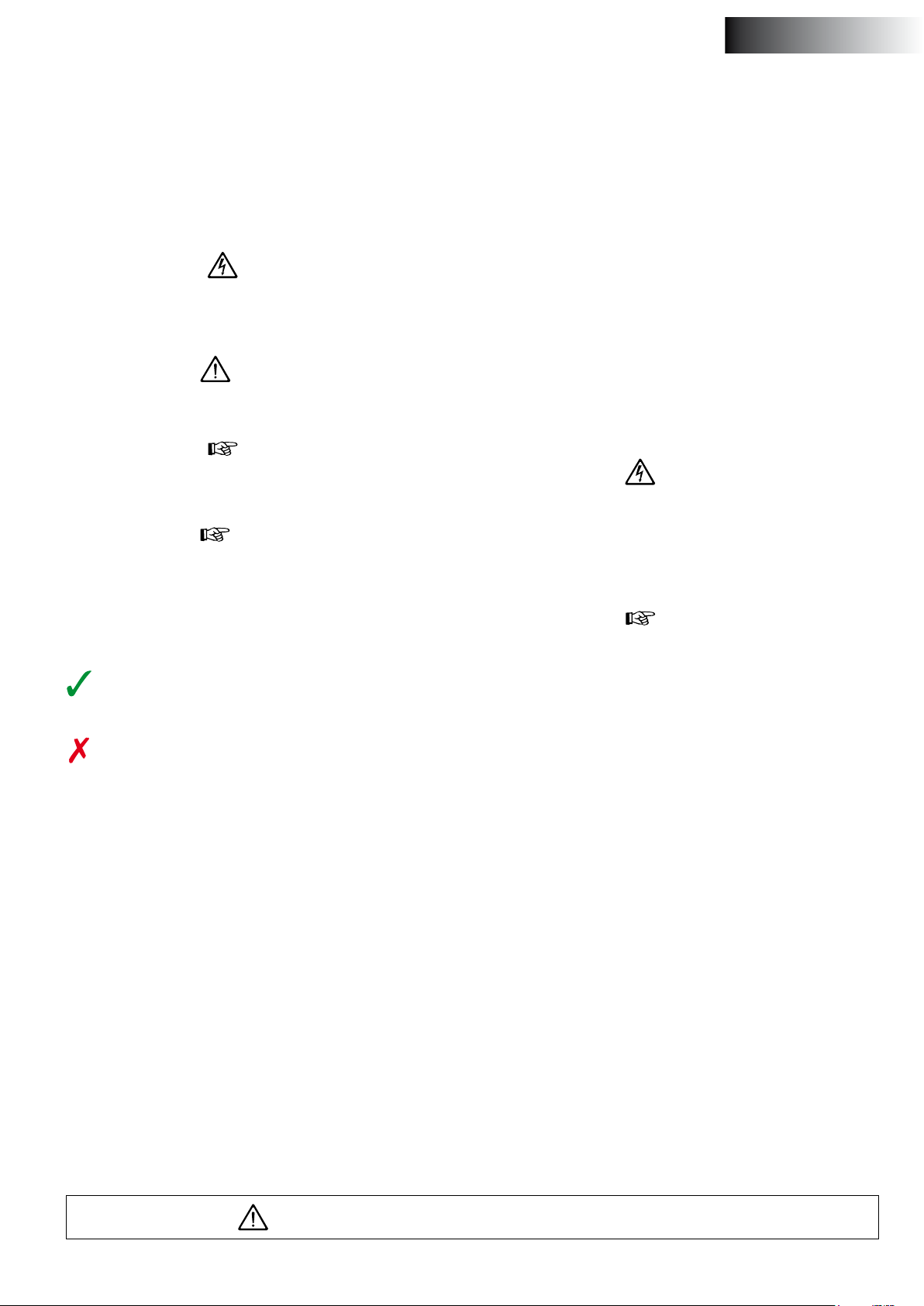
ITALIANO
1 Introduzione
1.1 Sicurezza
Indicazioni di avvertimento
Nel presente manuale sono state impiegate le seguenti indicazioni di
avvertimento ai ni della sicurezza:
pericoLo
Indica un potenziale pericolo che può essere causa di gravi infortuni
o di morte.
avvertimento
È un commento che indica la possibilità di danneggiamento del caricabatterie.
attenzione
Evidenzia procedure importanti, situazioni particolari, ecc.
suGGerimento
È un commento che, se osservato, semplica le operazioni di funzionamento del caricabatterie!
2 Informazioni
2.1 Scopo di questo manuale
Questo manuale fornisce informazioni importanti, necessarie per l’utilizzo sicuro e corretto del caricabatterie. È necessario, quindi, osservare le istruzioni per prevenire pericoli per l’utente!
Leggere con attenzione ed in modo completo il manuale, ed osservare tutte le informazioni ivi riportate per aumentare l’adabilità
dell’installazione e per allungare la durata del caricabatterie.
Chiunque utilizzerà il caricabatterie deve leggere questo manuale.
Prima di accendere il caricabatterie per la prima volta, devono essere
stati letti tutti i capitoli di questo manuale con attenzione ed in modo
completo.
3 Sicurezza personale
3.1 Generale
pericoLo
Il caricabatterie può emettere tensioni pericolosamente alte!
Il caricabatterie può essere aperto e riparato esclusivamente da un
elettricista.
Prima di aprire il caricabatterie scollegare sempre la rete di fornitura
d’energia elettrica e le batterie.
Simboli
Indica che deve essere eettuata una determinata operazio-
ne.
Indica che è vietato eettuare una determinata operazione.
Comunicate le indicazioni relative alla sicurezza a tutte le persone
che utilizzano il caricabatterie.
Osservate sempre tutte le norme e disposizioni di legge relative alla
sicurezza ed alla prevenzione degli infortuni.
1.2 Generale
Il caricabatterie totalmente automatico VETUS è decisamente adatto
per il caricamento rapido ed eciente di molti tipi di batterie acidopiombo (per caricare batterie a uido sia aperte, sia ermetiche, batterie al gel, batterie a semitrazione o batterie AGM).
Fare riferimento ai dettagli tecnici per le informazioni riguardanti la
tensione massima di carica. Poiché la tensione di carica è regolata in
modo totalmente automatico, in base ad un tipo di carica ottimale,
il caricatore può restare sempre collegato, anche durante i periodi
d’immagazzinamento.
Il caricabatterie è dotato di più uscite per poter caricare contemporaneamente 2 o 3 batterie diverse (il tipo BC12151 ha 1 uscita!)
Il caricabatterie è progettato per reti di fornitura d’energia elettrica
CA 115V e 230V.
attenzione
Se non sono osservate le precauzioni di sicurezza durante l’utilizzo
del caricabatterie, tutte le forme di garanzia e di responsabilità del
produttore/fornitore sono annullate.
3.2 Utilizzo
Il caricabatterie è progettato esclusivamente per caricare batterie
acido-piombo.
A seconda delle impostazioni possono essere caricate batterie a liquido sia aperte, sia ermetiche, batterie al gel, batterie a semitrazione
o batterie AGM.
Osservare le seguenti istruzioni del produttore.
Il caricabatterie non è adatto per tutti gli altri tipi di batteria e per
le batterie non ricaricabili!
Il caricabatterie può essere utilizzato esclusivamente in condizioni
tecniche perfette. Nel caso in cui si verichino disfunzioni che possono minare la sicurezza dell’utente e della nave, il caricabatterie deve
essere spento immediatamente.
Per ragioni di sicurezza è proibito eseguire qualsiasi tipo di rettica
all’apparecchiatura.
Le riparazioni (e.g. sostituzione del fusibile dell’alimentazione diretta) possono essere eseguite esclusivamente da personale specializzato nel campo.
La messa a terra di sicurezza deve essere osservata.
Assicurarsi che il proprietario dell’imbarcazione disponga del manuale.
vetus® Battery chargers BC12151, BC12252, BC12352, BC12503, BC12803, BC24122, BC24253, BC24403
090141.01 25

4 Caratteristiche
5 Installazione
- Indicato per tutte le fonti di corrente alternata comunemente usate e dotato di correzione cos phi.
- Indicato per batterie piombo/acido, batterie a gel e AGM.
- Supporto telecomando BCRP come accessorio opzionale.
- Compensazione tensione / temperatura mediante sensore di temperatura opzionale.
- Velocità ventilatore a 2 fasi (modalità sleep).
- Capacità uscita segnale OK
- Uscita segnale allarme.
- Elevato rendimento ed alta adabilità
- Funzione salvabatteria incorporata
- Dotato di uscita per funzione Starter (ESB)
- Protezione contro cortocircuito / sovratensione / sovratemperatura / caduta tensione di rete (Brown-out).
- Resistente alla prova di vibrazione a 2g.
Il caricabatterie VETUS presenta le caratteristiche di carica riportate
nella gura 14.1 a pag. 36.
4.1 Informazioni relative alle caratteristiche di
carica
1 Fase Bulk (CC, Corrente Continua)
All’inizio del processo di carica, la batteria scarica viene caricata a corrente continua (corrente di carica massima) no al raggiungimento
della tensione di carica impostata (Vedi gura 14.3 S1-Impostazioni).
2 Fase di Assorbimento (CV, Voltaggio Costante)
La durata della carica per assorbimento dipende dallo stato della batteria.
Il caricabatterie attende 2 minuti prima di passare alla fase di assorbimento, dopodiché procede alla carica a tensione costante no alla
carica completa della batteria.
La fase di assorbimento si conclude quando la batteria è completamente carica, o se la corrente di carica rimane inferiore al 6,25% della
corrente di carica nominale per 15 minuti.
3 Fase Float
Dopo la fase di assorbimento, il caricabatterie passa alla fase Float,
nella quale mantiene la batteria al 100% di carica, senza sovraccaricarla e senza danneggiarla. Per questo il caricabatterie può restare
costantemente collegato con la batteria.
4 Fase di Ricondizionamento
Ogni 12 giorni il caricabatterie torna automaticamente alla Fase Bulk
per 85 minuti, per dare nuova carica alla batteria. Ciò previene sintomi da stress, come la solfatazione.
5.1 Collocazione
Scegliere un luogo asciutto ad una distanza considerevole da qualsisia sorgente di calore.
Le alte temperature inuenzano in modo negativo la capacità
dell’apparecchiatura.
Per questo motivo non si devono coprire mai le aperture atte alla
ventilazione, ed è necessario mantenere uno spazio libero di almeno
10 cm attorno al caricabatterie.
Non collocare il caricabatterie troppo lontano dalla batteria per ridurre il più possibile la perdita di voltaggio nei cavi di collegamento
(rispettivamente 12V e 24V). Se necessario è meglio allungare la linea
a 230V.
avvertimento
Non collocare il caricabatterie direttamente sulla batteria; i fumi sulfurei della batteria possono provocare danni alle parti elettroniche.
L’apparecchiatura è conforme al livello di protezione IP 20.
Fissare il caricabatterie alla parete in posizione verticale con i collegamenti posti verso il basso; fare riferimento al capitolo “ 15 Dimensioni
principali”.
attenzione
Non trapanare fori di ssaggio aggiuntivi nella copertura di metallo!
La presenza di particelle metalliche nel caricabatterie può provocare danni irreparabili.
5.2 Collegamenti delle batterie
avvertimento
Scollegare innanzi tutto la rete di fornitura d’energia elettrica prima
di collegare o scollegare le batterie.
attenzione
Il voltaggio della batteria deve corrispondere ai dettagli del caricabatterie!
Fare riferimento al capitolo “13 Diagrammi dei circuiti elettrici” per
vedere come il caricabatterie deve essere collegato alle batterie.
Utilizzare cavi di spessore suciente ed utilizzare fondelli di cavo;
fare riferimento al capitolo “10 Tavola di selezione dei cavi” per la selezione del diametro corretto.
suGGerimento
Si consiglia di utilizzare cavi con protezione dai cortocircuiti o cavi
batteria intrecciati per essere conformi con le direttive CE.
avvertimento
Il grande usso di corrente in cavi troppo sottili, oppure il trasferimento di resistenza causato da collegamenti non corretti, può provocare il surriscaldamento di cavi o collegamenti (spine) causando
incendi.
26 090141.01
vetus® Battery chargers BC12151, BC12252, BC12352, BC12503, BC12803, BC24122, BC24253, BC24403

attenzione
Osservare la corretta polarità quando si collega il caricabatterie alla
batteria!
Collegare per prima cosa i cavi positivi (+) ed inne i cavi negativi
(-).
5.3 Diodo di separazione
ITALIANO
5.6 Pannello di controllo remoto (BCRP)
Fare riferimento al capitolo “14.13 Pannello di controllo remoto” per
collegare un pannello di controllo remoto optional.
L’allacciamento 6 polare RJ (CN4) è dedicato al pannello di controllo
remoto.
Il caricabatterie è fornito di un diodo di separazione così che si possono caricare diverse batterie, separate le une dalle altre (tranne il
modello BC12151).
Per permettere la ricarica separata delle batterie da parte della dinamo è necessario installare un diodo di separazione. Installare il diodo
di separazione Vetus a tensione stabilizzata o, in alternativa, compensare la tensione di carica della dinamo.
5.4 Impostazione della tensione di carica
Impostate la tensione di carica del caricabatterie per il tipo di batteria
piombo/acido da caricare. Vedi tabella 14.4 a pagina 38.
5.5 Sensore temperatura (BCTS)
Se, in climi tropicali o a causa di altre condizioni, la batteria diventa
molto calda, si consiglia di regolare il tipo di carica per queste temperature (alte) delle batterie. Ciò è reso possibile dal sensore di temperatura, disponibile come accessorio optional presso la VETUS.
Fare riferimento al capitolo “14.12 Sensore temperatura” per collegare un sensore di temperatura optional.
L’allacciamento 6 polare RJ (TEMP/CN3) è dedicato al sensore di temperatura.
Collocare il sensore di temperatura sulla batteria che raggiungerà la
temperatura più alta.
5.7 Collegamento alla rete di fornitura d’energia
elettrica
Il caricabatterie è progettato per reti di fornitura d’energia elettrica
CA 115V e 230V.
Si consiglia di eseguire il collegamento di messa a terra per il caricabatterie per essere conformi alle direttive CE.
avvertimento
È utile eseguire il collegamento di messa a terra per l’apparecchiatura elettrica a 230 Volt a bordo di una nave che non sia collegata
alla banchina ad una presa con protezione per la dispersione a terra,
e che sia dotata di protezione per le dispersioni di tensione oppure
d’isolamento di protezione (rete d’alimentazione mobile).
Consultare, al riguardo, il proprio installatore.
Inoltre i regolamenti locali e le loro applicazioni, che possono dierire tra i vari paesi, possono essere importanti (spesso sono applicate
regole speciali per navi da trasporto ed in particolare alle navi passeggeri).
La VETUS non può assumersi la responsabilità per l’utilizzo del caricabatterie in modo contrario alle disposizioni locali.
6 Uso
Dopo il collegamento della batteria, la carica inizia automaticamente
ed il LED “STATUS” si accende per indicare lo stato di carica.
7 Guasti
Guasto / Indicazione LED Possibile causa Soluzione
Rosso, lampeggia lentamente.
Rosso, lampeggia velocemente.
Rosso, a luce ssa.
Rosso, doppio lampeggio. Guasto al ventilatore. Controllate che il ventilatore non sia sporco o danneggiato.
Rosso, lampeggia lenta-
mente ogni 2 sec.
Tensione della batteria troppo
bassa o batteria sovraccarica.
Batteria difettosa. Sostituite la batteria.
La batteria o il caricabatterie
hanno una temperatura eccessiva.
Cortocircuito o collegamento
invertito (inversione polo + e
-).
Guasto alla Batteria Secondaria Extra.
Controllate la batteria.
Spegnete e riaccendete il caricabatterie.
Migliorate la ventilazione della batteria o del caricabatterie.
Assicuratevi che nessuna delle aperture di ventilazione sia ostruita.
Se possibile, abbassate la temperatura ambientale.
Collegate la batteria secondo la polarità corretta.
Risolvete il cortocircuito.
Vericate che il fusibile non sia bruciato e, se necessario, sostituitelo.
Controllate che l'allacciamento per la batteria extra non sia in cortocircuito.
vetus® Battery chargers BC12151, BC12252, BC12352, BC12503, BC12803, BC24122, BC24253, BC24403
090141.01 27

8 Velocità del ventilatore
La velocità del ventilatore dipende dal carico e dalla temperatura del
corpo refrigerante.
1 Velocità ventilatore 100%:
- Con un carico ≥ 75%
- Con un carico ≥ 50% ed una temperatura del corpo refrigerante
≥ 50 ºC
- Con una temperatura del corpo refrigerante ≥ 75 ºC
2 Velocità ventilatore 50%:
- Con una temperatura del corpo refrigerante ≥ 67,5ºC
3 Velocità ventilatore 0%:
- Con un carico < 75%
- Con una temperatura del corpo refrigerante <35 ºC
9 Dati tecnici
Tipo BC12151 BC12252 BC12352 BC12503 BC12803 BC24122 BC24253 BC24403
Tensione di alimentazione 90 - 264 V AC
Range di frequenza 47 - 63 Hz
Cos phi (nominale) > 0,92 a pieno carico
Rendimento (nominale) a 230 V AC 87 % 87 % 87 % 87 % 87 % 90% 90% 90%
Potenza massima assorbita: 250 W 400 W 550 W 800 W 1300 W 400 W 800 W 1250 W
Tensione nominale della batteria: 12 V 24 V
Tensione di carica Boost
Tensione di carica Float
Corrente nominale di carica 15 A 25 A 35 A 50 A 80 A 12 A 25 A 40 A
Numero di uscite isolate 1 2 2 3 3 2 3 3
Caratteristica di carica: IUoU, Corrente di carica limitata, tensione di carica (equalizzata), tensione di manutenzione (oat)
Uscita ESB 1 1 1 -- -- -- -- -Tensione / corrente uscita ESB 13,8 V / 2 A -- -- -- -- -Sistemi di protezione,
Tensione troppo elevata
Temperatura troppo elevata
Funzioni aggiuntive
Segnale di allarme Collegare e scollegare i relè (vedi 14.7 CN2 Allarmi e ventilatore)
Compensazione della temperatura -10 mV / 0,5 °C con sensore di temperatura
Modalità Sleep Mediante telecomando ed interruttore S1-4 DIP (vedi 14.3)
Temperatura ambiente Durante l’uso: da - 10 °C a +50 °C, a riposo: da - 20 °C a +70 °C
Umidità relativa da 20 a 90 % senza condensa
Coeciente di temperatura ± 0,03 % ( 0 -50 °C)
Vibrazione 10 - 500 Hz, 2G 10 min. / 1 periodo da 60 min lungo ciascun asse X, Y e Z
Grado di protezione IP20
Dimensioni [mm]: 205 x 84 x 259
Peso [kg] 1,6 1,7 1,9 3,1 4,0 1,6 2,9 3,9
sistema di protezione mediante disattivazione uscita (ripristino dopo scollegamento e nuovo col-
Il caricabatterie ha una temperatura superiore a 100 °C ± 5 °C, misurata a livello del prolo di refriger-
(Impostabile con interruttore S1 DIP)
(Impostabile con interruttore S1 DIP)
Ripristino automatico quando la temperatura del prolo di refrigerazione scende a 50 ±5 °C
14,4 V / 14,7 V
(Impostabile con interruttore S1 DIP)
13,8 V / 13,5 V
(Impostabile con interruttore S1 DIP)
> 17,5 V ± 1 % > 35 V ± 1 %
legamento alla tensione di rete).
azione.
52 ±5 °C (Sensore di temperatura opzionale)
-20 mV / 0,5 °C con sensore di tem-
205 x 84 x
279
237 x 90 x
288
237 x 90 x
328
205 x 84 x
259
28,8 V / 29,4 V
27,6 V / 27,0 V
peratura
237 x 90 x
288
237 x 90 x
328
28 090141.01
vetus® Battery chargers BC12151, BC12252, BC12352, BC12503, BC12803, BC24122, BC24253, BC24403

10 Draadkeuzetabel
Drahtwahltafel
Tabla de selección de hilos
Wire size selection table
Acculader
Battery charger
Batterieladegerät
Chargeur de batterie
Cargador de batería
Caricabatterie
BC12151
BC12252
BC12352
BC12503
BC12803
BC24122
BC24253
BC24403
Total length of positive and negative cables
Gesamtlänge des Plus- und Minuskabels
Longeur totale des câbles pos. et neg.
Largo total de los cables positivo y negativo
Lunghezza totale cavo positivi e negativi
0 - 11 m 2.5 mm
0 - 13 m 6 mm
0 - 14 m 10 mm
Tableau de selection de ls
Totale lengte plus- en minkabel
0 - 7 m 4 mm
0 - 20 ft AWG 12
0 - 6 m 6 mm
0 - 19 ft AWG 10
0 - 8 m 10 mm
0 - 21 ft AWG 8
0 - 5 m 10 mm
0 - 24 ft AWG 6
0 - 5 m 16 mm
0 - 24 ft AWG 4
0 - 50 ft AWG 12
0 - 38 ft AWG 10
0 - 38 ft AWG 6
Tabella di selezione dei cavi
Draaddoorsnede
Wire size
Leiterquerschnitt
Diamètre du l
Diámetro de hilo
Diametro del lo
2
2
2
2
2
2
2
2
11 Acculaderkeuze
Battery charger selection
Acculader
Battery charger
Batterieladegerät
Chargeur de batterie
Cargador de batería
Caricabatterie
BC12151 50 - 80 Ah
BC12252 80 - 125 Ah
BC12352 125 - 175 Ah
BC12503 175 - 250 Ah
BC12803 250 - 400 Ah
BC24122 50 - 80 Ah
Auswahl des Batterieladegeräts
Choix du chargeur de batterie
Geschikt voor een accucapaciteit in Ah, bij een laadtijd van 6 tot 24 uur
Suitable for a battery capacity in Ah, at a charging time of 6 to 24 hours
Geeignet für eine Batteriekapazität in Ah bei einer Ladezeit von 6 bis 24 Stunden
Convient pour une capacité de batterie en Ah, avec un temps de charge de 6 à 24 heures
Adecuado para la capacidad de la batería en Ah, a un tiempo de carga de 6 a 24 horas
Idoneo per la capacità di una batteria in Ah, ad una durata di carica da 6 a 24 ore
Elección de cargador de baterías
Scelta del caricabatterie
BC24253 80 - 125 Ah
BC24403 125 - 200 Ah
vetus® Battery chargers BC12151, BC12252, BC12352, BC12503, BC12803, BC24122, BC24253, BC24403
090141.01 29

12 Aansluittekeningen Connection drawings Anschlusszeichnungen
21
BC12151
3
4 5 6
7
8 9 10
21
BC12252
BC12352
BC24122
30 090141.01
3
vetus® Battery chargers BC12151, BC12252, BC12352, BC12503, BC12803, BC24122, BC24253, BC24403
4 5 6
7
8 9 10

Schémas de raccordement Esquemas de conexiones Graci dei collegamenti
BC12503
BC12803
1
3
4 5 6
2
BC24253
BC24403
1 Aan/uitschakelaar On/O switch Ein-Ausschalter
2 Status LED Status LED Status LED
3 Keuzeschakelaar S1, zie 14.3 Selector switch S1, see 14.3 Wählschalter S1, Siehe 14.3
4 CN2, zie 14.7 CN2, see 14.7 CN2, Siehe 14.7
5 TEMP/CN3, zie 14.9 en 14.12 TEMP/CN3, see 14.9 and 14.12 TEMP/CN3, Siehe 14.9 und 14.12
6 CN4, zie 14.11 en 14.13 CN4, see 14.11 and 14.13 CN4, Siehe 14.11 und 14.13
7 Accuaansluitingen + Battery connections + Batterieanschlüsse +
8 Accuaansluiting - Battery connection - Batterieanschluss 9 Aanluiting startaccu Starter battery connection Starterbatterie-Anschluss
10 Aansluitingen netspanning (IEC) Connections mains voltage (IEC) Anschlüsse Netzspannung (IEC)
1 Commutateur marche/arrêt Interruptor encendido/apagado Interruttore On/O
2 Status LED Status LED Status LED
3 Commutateur de choix S1, voir 14.3 Conmutador selector S1, ver 14.3 Selettore S1, vedere 14.3
4 CN2, voir 14.7 CN2, ver 14.7 CN2, vedere 14.7
5 TEMP/CN3, voir 14.9 et 14.12 TEMP/CN3, ver 14.9 y 14.12 TEMP/CN3, vedere 14.9 e 14.12
6 CN4, voir 14.11 et 14.13 CN4, ver 14.11 y 14.13 CN4, vedere 14.11 e 14.13
7 Raccordements de batterie + Conexiones de la batería + Collegamenti della batterie +
8 Raccordement de batterie - Conexion de la batería - Collegamento della batterie 9 Raccordement de la batterie de démarrage Conexión de la batería de arranque Collegamento della batteria di avviamento
Tension d’alimentation de raccordement
10
(IEC)
7
Conexión al voltaje de la red eléctrica (IEC)
8 10
Collegamenti della rete di fornitura
d’energia elettrica (IEC)
vetus® Battery chargers BC12151, BC12252, BC12352, BC12503, BC12803, BC24122, BC24253, BC24403
090141.01 31

1
1
1
13 Elektrische schema’s Electrical circuit diagrams Verdrahtungsschemata
13.1 BC12151
2
B+
6
MODEL
BC12153 15 A max. 20 A 2 A max.
13.2 BC24152
BC12151
5
3
I1 I4
4
1
2
B+
8
BC12151
7
1
6
I1 I4
4
5 A
5
3b
I1
5 5
3 3b
FUSE (4)
4
4
5 A
I4
2
B+
BC24152
6
I1 I2
4
5
3
MODEL
4
5
3
I1 I2
2
B+
8
BC24152
7
6
4
5
5
3
BC24152 15 A max. 15 A max. 20 A
I1 I2
4
3
FUSE (4)
2
BC24152
B+
6
I1 I2
4
5
3
MODEL
I1 + I2
FUSE (4)
BC24152 15 A max. 20 A
1 Acculader Battery charger Batterielader 1 Chargeur de batteries Cargador de baterías Caricabatterie
2 Dynamo Dynamo Dynamo 2 Dynamo Dinamo Dinamo
3 Accu Battery Batterie 3 Batterie Batería Batteria
4 Zekering Fuse Sicherung 4 Fusible Fusible Fusibile
5 Boordnet 12 Volt resp. 24 Volt Board mains 12 Volt resp. 24 Volt Bordnetz 12 Volt bzw. 24 Volt 5 Réseau de bord 12 volts ou 24 volts
6 Startmotor Starting motor Startmotor 6 Moteur de démarrage Arranque del motor Motore d’avvio
7 Scheidingsdiode Separation diode Trenndiode 7 Diode de séparation Diodo de separación Diodo di separazione
8 Originele draad, te verwijderen! Original wire, to be removed! Originalkabel, zu entfernen! 8 Fil d’origine, à enlever! Hilo original, ja ser retirado! Cavo originale, da rimuovere!
32 090141.01
vetus® Battery chargers BC12151, BC12252, BC12352, BC12503, BC12803, BC24122, BC24253, BC24403

Schémas électriques Diagramas de los circuitos
Diagrammi dei circuiti
13.3 BC12252, BC12352
2
B+
6
5
3
MODEL
BC12252 25 A max. 25 A max. 40 A 2 A max.
BC12352 35 A max. 35 A max. 50 A 2 A max.
BC12252
BC12352
4
5 5
I1 I2
I4
4
3 3b
I1 I2
eléctricos
1
2
B+
8
7
BC12252
BC12352
elettrici
1
6
I1 I2
4
5 A
4
5
3
4
5 5
3 3b
FUSE (4)
I4
4
5 A
I4
2
6
B+
MODEL
5
BC12252
BC12352
4
3
I1 I2
I4
5
3b
1
4
5 A
I1 + I2
2
BC12252
BC12352
B+
8
7
6
I1 I2
4
5 5
3 3b
FUSE (4)
BC12252 25 A max. 40 A 2 A max.
BC12352 35 A max. 50 A 2 A max.
1
I4
4
5 A
I4
Suministro eléctrico de a bordo 12 Volt resp.
24 Volt
vetus® Battery chargers BC12151, BC12252, BC12352, BC12503, BC12803, BC24122, BC24253, BC24403
Schede rete di fornitura d’energia elettrica rispettivamente 12 Volt e 24Volt
090141.01 33

13.4 BC12503, BC12803, BC24253, BC24403
2
B+
BC12503
BC12803
BC24253
BC24403
1
2
B+
8
6
I1 I2 I3
6
BC12503
BC12803
7
I1 I2 I3
4 4 4
4 4 4
5
3
MODEL
5 5
3 3
I1 I2 I3
5
3
5 5
3 3
BC12503 40 A max. 40 A max. 40 A max. 50 A
BC12803 40 A max. 40 A max. 40 A max. 50 A
BC24253 25 A max. 25 A max. 25 A max. 40 A
BC24403 40 A max. 40 A max. 40 A max. 50 A
BC24253
BC24403
1
FUSE (4)
2
B+
BC12503
BC12803
7
6
I1 I2 I3
BC24253
BC24403
1
2
B+
8
6
BC12503
BC12803
7
I1 I2 I3
4 4
4 4
5
3
MODEL
5
3
I1 + I2
FUSE (4)
5
3
I3
5
3
BC12503 50 A max. 60 A 40 A max. 50 A
BC12803 80 A max. 100 A 40 A max. 50 A
BC24253 25 A max. 40 A 25 A max. 40 A
BC24403 40 A max. 50 A 40 A max. 50 A
BC24253
BC24403
FUSE (4)
1
1 Acculader Battery charger Batterielader 1 Chargeur de batteries Cargador de baterías Caricabatterie
2 Dynamo Dynamo Dynamo 2 Dynamo Dinamo Dinamo
3 Accu Battery Batterie 3 Batterie Batería Batteria
4 Zekering Fuse Sicherung 4 Fusible Fusible Fusibile
5 Boordnet 12 Volt resp. 24 Volt Board mains 12 Volt resp. 24 Volt Bordnetz 12 Volt bzw. 24 Volt 5 Réseau de bord 12 volts ou 24 volts
6 Startmotor Starting motor Startmotor 6 Moteur de démarrage Arranque del motor Motore d’avvio
7 Scheidingsdiode Separation diode Trenndiode 7 Diode de séparation Diodo de separación Diodo di separazione
8 Originele draad, te verwijderen! Original wire, to be removed! Originalkabel, zu entfernen! 8 Fil d’origine, à enlever! Hilo original, ja ser retirado! Cavo originale, da rimuovere!
34 090141.01
vetus® Battery chargers BC12151, BC12252, BC12352, BC12503, BC12803, BC24122, BC24253, BC24403

2
B+
BC12503
BC12803
BC24253
BC24403
1
6
I1 I2 I3
4
5
3
MODEL
I1 + I2 + I3
FUSE (4)
BC12503 50 A max. 60 A
BC12803 80 A max. 100 A
BC24253 25 A max. 40 A
BC24403 40 A max. 50 A
Suministro eléctrico de a bordo 12 Volt resp.
24 Volt
vetus® Battery chargers BC12151, BC12252, BC12352, BC12503, BC12803, BC24122, BC24253, BC24403
Schede rete di fornitura d’energia elettrica rispettivamente 12 Volt e 24Volt
090141.01 35

14 Instellingen en informatie
Settings and information Einstellungen und Informationen
14.1 Accu laadcurve Battery Charging Curve Akkuladekennlinie
BULK (CC) ABSORPTION (CV) F L OAT RECONDITION F LOAT BULK (CC)
14.4 / 28.8 V
13.8 / 27.6 V
12.8 / 25.6 V
6.25% I nom.
Laad-fase
Laadspecicatie
Charging stage
Charging spec
Ladephase
Ladespezikati-
onen
Spanning Voltage
Stroom Current
Spannung Tension
Strom Courant
Voltaje Voltaggio
Corriente Corrente
BULK (CC) ABSORPTIE (CV) FLOAT RECONDITIONEREN FLOAT BULK (CC)
2 min - 8 uur 0,25 uur - 24 uur 2 weken 85 min 2 weken 2 min - 8 uur
Verminderd de laadtijd
door het opladen met
maximale stroom (con-
stante stroom modus)
Opladen bij nominale
stroom
Zorgt ervoor dat de accu
volledig is opgeladen zonder
dat deze overladen wordt
(Constante spanning modus)
14,4 V / 28,8 V totdat de stroom
is gedaald tot 6,25% van de
nominale stroom
In stand houden
van de 100%
laadtoestand van
de accu.
Blijft op 13,8 V /
27,6 V
Reconditioneren van
de accu
14,4 V / 28,8 V met een
nominale stroom
In stand houden
van de 100%
laadtoestand van
de accu.
Blijft op 13,8 V /
27,6 V
Zodra de accuspan-
ning lager is dan 12,8
V / 25,6 V zal na 30
seconden, zal de lader
terugkeren van de
FLOAT naar de BULK
fase
BULK (CC) ABSORPTION (CV) FL OAT RECONDITION F LOAT BULK (CC)
2 min - 8 hours 0.25 hours - 24 hours 2 weeks 85 min 2 weeks 2 min - 8 hours
Reduce charging time
by charging at maxi-
mum current (Constant
current mode)
Charging at rated
current
HAUPTLADUNG (CC) NACHLADUNG (CV)
2 Min. - 8 Stunden 0,25 Stunden - 24 Stunden 2 Wochen 85 Min. 2 Wochen 2 Min. - 8 Stunden
Verringert die Ladezeit
durch das Auaden mit
maximalem Strom (Kon-
stantstrommodus)
Auaden bei Nennstrom
Make sure the battery is fully
charged without overcharging
(Constant voltage mode)
14.4 V / 28.8 V until the current
drops to 6.25% of rated current
Lädt den Akku vollständig
auf, ohne diesen zu überladen
(Konstantspannungsmodus)
14,4 V/ 28,8 V bis der Strom
auf 6,25 % des Nennstroms
abgesunken ist
Maintain the
battery at 100%
charge condition
Stay at 13.8 V /
27.6 V
ERHALTUNGS-
LADUNG
Erhält den 100
% aufgeladenen
Zustand des
Akkus.
Bleibt auf 13,8 V/
27,6 V
Reconditioning the
battery
14.4 V / 28.8 V with
rated current
AUSGLEICHSLA-
DUNG
Ausgleichsladen der
Batterie
14,4 V/ 28,8 V mit
einem Nennstrom
Maintain the
battery at 100%
charge condition
Stay at 13.8 V /
27.6 V
ERHALTUNGS-
LADUNG
Erhält den 100 %
aufgeladenen Zu-
stand des Akkus.
Bleibt auf 13,8 V/
27,6 V
Once battery voltage
is below 12.8 V / 25.6
V after 30 seconds, the
charger will turn from
FLOAT to BULK
HAUPTLADUNG
(CC)
Sobald die Akkuspan-
nung niedriger als
12,8 V/ 25,6 V wird,
schaltet das Ladegerät
nach 30 Sekunden
von ERHALTUNGSLADUNG auf HAUPTLA-
DUNG zurück.
36 090141.01
vetus® Battery chargers BC12151, BC12252, BC12352, BC12503, BC12803, BC24122, BC24253, BC24403

Réglages et informations
Ajustes e información Impostazioni ed informazioni
Courbe de charge de la batterie Curva de carga de la batería Curva di carica della batteria
BULK (CC) ABSORPTION (CV) F L OAT RECONDITION F LOAT BULK (CC)
14.4 / 28.8 V
13.8 / 27.6 V
12.8 / 25.6 V
6.25% I nom.
Phase de charge
Spécications de
charge
Etapa de carga
Especicaciones
de carga
Fase di carica
Speciche di
carica
Spanning Voltage
Stroom Current
BULK (CC) ABSORPTION (CV) FL OAT
2 min - 8 heures 0,25 heure - 24 heures 2 semaines 85 min 2 semaines 2 min - 8 heures
Réduit le temps de char-
ge en chargeant avec un
courant maximal (mode
courant constant)
Charge à courant
nominal
Veille à ce que la batterie soit
complètement chargée sans
être en surcharge (mode de
tension constante)
14,4 V / 28,8 V jusqu'à ce que le
courant soit descendu à 6,25 %
du courant nominal
Spannung Tension
Strom Courant
RECONDITIONNE-
Maintien de l'état
de charge à 100
% de la batterie.
Se maintient à
13,8 V / 27,6 V
Reconditionnement de
la batterie
14,4 V / 28,8 V avec un
courant nominal
MENT
Voltaje Voltaggio
Corriente Corrente
FLOAT BULK (CC)
Maintien de l'état
de charge à 100 %
de la batterie.
Se maintient à
13,8 V / 27,6 V
Dès que la tension
de batterie descend
en dessous de 12,8 V
/ 25,6 V, le chargeur
secondes de la phase
FLOAT à la phase BULK
passera après 30
BRUTA (CC) ABSORCIÓN (VC) FLOTACIÓN ECUALIZACIÓN FLOTACIÓN BRUTA (CC)
2 min - 8 horas 0,25 horas - 24 horas 2 semanas 85 min 2 semanas 2 min - 8 horas
Reduce el tiempo de
carga cargando con cor-
riente máxima (modo
de corriente continua).
Carga con corriente
nominal
Hace que la batería se cargue
por completo sin sobrecargar-
se (modo de tensión continua).
14,4 V / 28,8 V hasta que la
corriente haya bajado al 6,25%
de la corriente nominal
BULK (CC) ASSORBIMENTO (CV) F LOAT
2 min - 8 ore 0,25 ore - 24 ore 2 settimane 85 min 2 settimane 2 min - 8 ore
Riduce il tempo di carica
mediante la carica con
corrente massima (moda-
lità corrente continua)
Carica con corrente
nominale
Fa si che la batteria venga ca-
ricata completamente senza
sovraccaricarla (Modalità
tensione costante)
14,4 V / 28,8 V no al calare
della corrente no al 6,25%
della corrente nominale
Mantenimiento
del estado de
carga al 100% de
la batería.
Se mantiene a
13,8 V / 27,6 V
Mantenimento
della carica della
batteria al 100%.
Rimane a 13,8 V /
27,6 V
Ecualización de la
batería
14,4 V / 28,8 V con cor-
riente nominal
RICONDIZIONA-
MENTO
Ricondizionamento
della batteria
14,4 V / 28,8 V con cor-
rente nominale
Mantenimiento
del estado de
carga al 100% de
la batería.
Se mantiene a
13,8 V / 27,6 V
En cuanto la tensión de
la batería baje de 12,8
V / 25,6 V, pasados 30
segundos el cargador
volverá a pasar de la
etapa de FLOTACIÓN a
la de CARGA BRUTA.
FLOAT BULK (CC)
Mantenimento
della carica della
batteria al 100%.
Rimane a 13,8 V /
27,6 V
Non appena la
tensione della batteria
scende al di sotto dei
12,8 V / 25,6 V, dopo 30
secondi, il caricabatterie passa dalla fase
FLOAT alla fase BULK.
vetus® Battery chargers BC12151, BC12252, BC12352, BC12503, BC12803, BC24122, BC24253, BC24403
090141.01 37

14.2 Laadstatusindicatie Charging status indication Ladestatusanzeige
Status LED
Kleur en patroon
status LED
Oranje ,snel Bulk-1 Orange, fast Bulk-1 Orange, schnell blinkend Hauptladung-1 Orange, rapide Bulk-1 Naranja, rápido Bruta-1 Arancione, rapido Bulk-1
Oranje, langzaam Bulk-2 Orange, slow Bulk-2 Orange, langsam blinkend Hauptladung-2 Orange, lent Bulk-2 Naranja, lento Bruta-2 Arancione, lento Bulk-2
Orange, continue Absorptie-1 Orange, solid Absorption-1
Groen, continue Absorptie-2 Green, solid Absorption-2
Groen, its Float Green, ash Float Grün, blinkend Erhaltungsladung Vert, clignotant Float Verde, relampagueo Flotación Verde, lampeggiante Float
Laadstatus
Colour and pat-
tern status LED
Charging
status
Farbe und Leuchtverhal-
ten der Status-LED
Orange, kontinuierlich
leuchtend
Grün, kontinuierlich
leuchtend
Ladestatus
Nachladung-1 Orange, continu Absorption-1 Naranja, continuo Absorción-1 Arancione, sso Assorbimento-1
Nachladung-2 Vert, continu Absorption-2 Verde, continuo Absorción-2 Verde, continuo Assorbimento-2
14.3 S1 (DIP Switch) instellingen S1 (DIP Swich) Settings S1 (DIP-Schalter)-Einstellungen
1 2 3 4
CC/CV Float CC/CV Float
ON X OFF X 14.4 V --- 28.8 V ---
OFF X OFF X 14.7V --- 29.4V ---
X ON OFF X --- 13.5V --- 27.0V
X OFF OFF X --- 13.8V --- 27.6V
12V 24V
Functie Function Funktion Fonction Función Funzione
Overschakelen constante
stroom naar constante
spanning
‘Float’ spanning
OFF OFF ON X 13.2V 26.4V
OFF ON ON X 13.8V 27.6V
ON OFF ON X 14.4V 28.8V
ON ON ON X --- --- --- --- Afstandsbediening
X X X ON --- --- --- ---
X X X OFF --- --- --- ---
Power Mode
(Uitgangsspanning bij
stroombegrenzing)
Slaapmode
X : Niet van toepassing
--- : Volgens standaard
instelling
14.4 Aanbevolen instellingen Recommended settings Empfohlene Einstellungen
12 v 24 v
CC/CV Float CC/CV Float
14.4 V 13.5 V 28.8 V 27.0 V
Vloeistofgevulde accu’s, zowel
Accu type Battery type Batterietyp Type de batterie Tipo de batería Tipo di batterie
Fluid lled batteries, both open
open- als gesloten accu’s.
and sealed batteries.
14.7 V 13.8 V 29.4 V 27.6 V Gel gevulde accu’s. Gel lled batteries. Gelbatterien. Les batteries remplies de gel. Baterías de gel. Batterie a base gel.
14.7 V 13.8 V 29.4 V 27.6 V Semi-tractie accu’s Deep cycle batteries. Semitraktionsbatterien Les batteries de semi-traction Baterías de semi tracción. Batterie a semitrazione.
14.4 V 13.5 V 28.8 V 27.0 V AGM accu’s AGM Batteries AGM Batterien. Les batteries de AGM Baterías de AGM Batterie a AGM.
38 090141.01
vetus® Battery chargers BC12151, BC12252, BC12352, BC12503, BC12803, BC24122, BC24253, BC24403

Indication de l’état de charge Indicación del estado de carga Indicazione dello stato di carica
Couleur et fonc-
tionnement LED
État de charge
Color y patrón de
iluminación del led
Estado de carga
Colore e schema di
stato dei LED
Stato di carica
Réglages (DIP Switch) S1 Ajustes del S1 (conmutador DIP) Impostazioni S1 (DIP Switch)
CC turn to CV voltage
Umschalten von Konstant-
strom auf Konstantspan-
nung
Passage d'un courant
constant à une tension
constante
Pasar de corriente continua
a tensión continua
Commutazione da cor-
rente continua a tensione
continua.
Float voltage Erhaltungsspannung Tension « Float » Tensión de "otación" Tensione "Float’
Power Mode
(Current limit output volt-
age)
Remote Fernbedienung Télécommande Control remoto Telecomando
Sleep mode Ruhemodus Mode Repos Modo de descanso Modalità di riposo
X : Not applicable
--- : By default setting
Betriebsmodus
(Ausgangsspannung bei
Strombegrenzung)
X : nicht zutreend
--- : Gemäß Standardeinstellung
Mode Power
(Tension de sortie lors
d'une limitation de cou-
rant)
X : Non applicable
--- : Selon le réglage
standard
Modo de energía
(Tensión de salida con
limitación de corriente)
X : No aplicable
--- : Según ajuste estándar
Modalità Power
(Tensione in uscita con
limitazione di corrente)
X : Non applicabile
--- : Secondo impostazioni standard
Réglages recommandés Ajustes recomendados Impostazioni consigliate
Nassbatterien, sowohl oene als
auch gasdichte Batterien.
vetus® Battery chargers BC12151, BC12252, BC12352, BC12503, BC12803, BC24122, BC24253, BC24403
Les batteries remplies de li-
quide, tant des batteries ouvertes
qu’étanches au gaz.
Baterías de líquido, tanto baterías
abiertas como estancas, baterías de ar-
ranque y baterías de semi tracción.
Batterie riempite di uido:
aperte e ermetiche.
090141.01 39

14.5 Standaard instellingen Default settings Standardeinstellungen
12 v 24 v
14.4 V 28.8 V CC turn to CV voltage
13.8 V 27.V Float voltage ‘Float’ spanning Erhaltungsspannung Tension « Float » Tensión de "otación" Tensione "Float’
O (O) O (O) Power Mode Power Mode Betriebsmodus Mode Power Modo de energía Modalità Power
O (O) O (O) Remote Afstandsbediening Fernbedienung Télécommande Control remoto Telecomando
Full speed (MAX.) Full speed (MAX.) Fan Ventilator Lüfter Ventilateur Ventilador Ventilatore
Function Functie Funktion Fonction Función Funzione
Overschakelen constante stroom
naar constante spanning
14.6 Storingsindicatie Fault indication Störungsanzeige
Status LED
Kleur en patroon status
LED
Rood, conti-
nue
Rood, snel
Beschrijving storing
Uitgangstroom is gereduceerd tot minder
dan 1 A
Onstabiele netspanning (walspanning)
Uitgangszekering
defect
Accu te hoge temperatuur
Accu te lage temperatuur
Lader te heet (Koelproel)
Colour and
pattern status
LED
Red, solid
Red, fast
Failure description
Output current is reduced to <1A
AC I/P unstable
Output FUSE blown
Battery over heated
*)
Battery under heat *)
Charger over heat
(Heat Sink)
Farbe und
Schema
Status-LED
Rot, kontinuierlich
leuchtend
Rot, schnell
blinkend
Beschreibung
Störung
Ausgangsstrom ist
reduziert auf unter
1 A
Instabile Netzspannung (Landspannung)
Ausgangssicherung
defekt
Akku zu hohe Temperatur
Akku zu niedrige
Temperatur
Ladegerät zu heiß
(Kühlprol)
Accuspanning te
hoog
Rood, lang-
zaam
Rood dubbele
lichtits
Rood lang-
zaam elke 2
sec.
*) Deze indicatie is alleen beschik-
baar als een temperatuurzender is
aangesloten.
Accuspanning te laag
of uitgangspanning
te laag in CC mode
(Bulk mode)
Ventilator afwijkend
gedrag
ESB geen uitgangsspanning / uitgang
kortgesloten
Red, slow
Red light ash
twice
Red slow
every 2 sec.
*) This indication is available only
when a temperature sensor is connected.
Battery over voltage
Battery under voltage or output under
voltage in C.C. mode.
Fan abnormality
ESB no output / output short
Rot, langsam
blinkend
Rot, blinkt 2 x
kurz
Rot, blinkt
langsam alle
2Sek.
*) Diese Anzeige ist nur verfügbar,
wenn ein Temperatursensor angeschlossen ist.
Akkuspannung zu
hoch
Akkuspannung zu
niedrig oder Ausgangsspannung zu
niedrig im CC-Modus
(Hauptladungsmodus)
Lüfter nicht normal
ESB keine Ausgangsspannung/
Ausgang Kurzschluss
40 090141.01
vetus® Battery chargers BC12151, BC12252, BC12352, BC12503, BC12803, BC24122, BC24253, BC24403

Réglages standard Ajustes estándar Impostazioni standard
Umschalten von Konstantstrom
auf Konstantspannung
Passage d'un courant constant à
une tension constante
Pasar de corriente continua a
tensión continua
Commutazione da corrente conti-
nua a tensione continua.
Indication de panne Indicación de avería Indicazione di malfunzionamento
Couleur et fonctionnement LED
Rouge, continu
Description de la panne
Le courant de sortie est
réduit à moins d'1 A
Tension de réseau instable (tension de quai)
Color y patrón
de iluminación
del led
Rojo, continuo
Descripción del fallo
La corriente de salida se
ha reducido a menos de
1 A.
Tensión de red inestable
(tensión de tierra)
Colore e schema
di stato dei LED
Rosso, sso
Descrizione del guasto
La corrente in uscita è
inferiore a 1 A
Tensione di rete instabile
(tensione di banchina)
Fusible de sortie défectueux
Température trop élevée
de la batterie
Température trop basse
Rouge, rapide
Rouge, lent
Rouge double
clignotement
Rouge, lent,
toutes les 2 s.
*) Cette indication est uniquement dispo-
nible si un capteur de température est
raccordé.
de la batterie
Chargeur trop chaud
(dissipateur thermique)
Tension de batterie trop
élevée
Tension de batterie trop
basse ou tension de sortie trop basse en mode
CC (mode Bulk)
Comportement inhabituel du ventilateur
Pas de tension de sortie
/court-circuit sur sortie
ESB
Fusible de salida estropeado
Temperatura excesiva en
batería
Temperatura insuciente
Rojo, rápido
Rojo, lento
Rojo parpadeo
doble
Rojo, lento cada 2
segundos.
*) Este indicador solo está disponible si hay un
emisor de temperatura conectado.
en batería
Cargador demasiado
caliente (disipador)
Tensión de batería excesiva
Tensión de batería insuciente o tensión de salida
insuciente en modo CC
(modo bruto)
Mal comportamiento
ventilador
ESB sin tensión de salida/
salida cortocircuitada
Fusibile dell'uscita difettoso
Temperatura batteria
troppo elevata
Temperatura batteria
Rosso, rapido
Rosso, lento
Rosso doppio ash
Rosso, lento ogni
2 sec.
*) Questa indicazione è disponibile solo se è
collegato un trasmettitore di temperatura.
troppo bassa
Caricabatterie troppo
caldo (Prolo di refrigerazione)
Tensione della batteria
troppo alta
Tensione della batteria
troppo bassa o tensione in
uscita troppo bassa in modalità CC (modalità Bulk)
Comportamento anomalo
del ventilatore
ESB nessuna tensione in
uscita / uscita in cortocircuito
vetus® Battery chargers BC12151, BC12252, BC12352, BC12503, BC12803, BC24122, BC24253, BC24403
090141.01 41

14.7 CN2 Alarmen en ventilator
CN2 Alarme und Lüfter
CN2 Alarmas y ventilador
CN2 Alarms and Fan control
Normaal ge-
1
opend
Normaal ge-
1 2 3 4 5
2
sloten
3 P-contact COM P-Kontakt Contact P Contacto P Contatto P
Slaapmode
4
aansturing
5 Massa GND Masse Masse Masa Massa
4-5 Slaap mode aan Sleep mode on
4-5 Slaap mode uit Sleep mode o
CN2 Alarmes et ventilateur
Normally
closed
Normaly open NC (Öner)
Sleep mode
control
NO (Schließer)
SchlafmodusSteuerung
Schlafmodus
ein
Schlafmodus
aus
Ouvert normalement
Fermé normalement
Commande du
Mode veille
Mode Veille
activé
Mode Veille
désactivé
CN2 Allarmi e ventilatore
Normal abierto
Normal cerrado
Control modo
hibernación
Modo de hibernación conectado
Modo de hibernación desconectado
Normalmente
aperto
Normalmente
chiuso
Comando modalità sleep
Modalità Sleep
accesa
Modalità Sleep
spenta
14.8 Slaap Mode Sleep Mode Schlafmodus
# BCRP CN2
A OFF ( O ) OFF ( O ) UIT
1)
Slaap mode Ventilator snelheid Sleep Mode Fan Speed
Het draaien van de ventilator is afhankelijk van de
temperatuur van het koellichaam en de belasting.
OFF
Fan will operate according to heat sink
temperature and
loads condition.
Schlafmo-
dus
AUS
Geschwindigkeit
Lüfter
Die Lüftergeschwindigkeit ist abhängig von
der Kühlköpertemperatur und der Last.
B OFF ( O ) ON ( I ) AAN
C ON ( I ) ON ( I )
D ON ( I ) OFF ( O )
Acht (8) uur na het gebruik van BCRP 2) om de
Slaap Mode te starten zal de slaap mode stoppen. Gebruik de BCRP om te bepalen of de
Slaap Mode moet worden ingeschakeld of niet.
1)
Raadpleeg par. 14-7.
2)
BCRP is het afstandsbedieningspaneel, en
daar kan de slaap mode op worden ingesteld.
AAN
(diepe slaap)
AAN
(diepe slaap)
Ventilator draait met 50%
inschakelduur
Ventilator staat stil.
Ventilator staat stil.
After 8 hours to use BCRP
Sleep Mode, then the sleep mode
will stop. Please use the CN2 to determine the Sleep Mode ON/OFF..
1)
Please refer to 14-7.
2)
BCRP is the remote control
panel, and sleep mode can be
set by this remote controller.
14.9 Pen bezetting CN3, Temperatuur sensor
Pin assigment of CN3, Temperatuur sensor
Pinbelegung CN3, Temperatursensor
Aectation de borne CN3, Capteur de température
ON
ON
(deep sleep)
ON
(deep sleep)
2)
to start
Fan operates at
50% duty.
Fan stop.
Fan stop.
Acht (8) Stunden nach Einsatz des Fernbedienungspanels BCRP
muss der Schlafmodus stoppen. Nutzen Sie das
Fernbedienungspanel BCRP, um festzulegen, ob der
Schlafmodus eingeschaltet werden soll oder nicht.
1)
Siehe Abs. 14-7.
2)
BCRP ist das Fernbedienungspanel, auf dem
der Schlafmodus eingestellt werden kann.
2)
um den Schlafmodus zu starten,
1 6
RJ-11 6P6C
EIN
EIN
(Tiefschlaf)
EIN
(Tiefschlaf)
1 R_VCC
2 GND
3 TEMP
4 BAT-
5 DATA I/O
6 BAT+
Lüfter läuft mit 50 %
Einschaltdauer
Lüfter steht still.
Lüfter steht still.
Esquema de pines CN3, sensor de temperatura
Pin CN3, Sensore di temperatur
42 090141.01
vetus® Battery chargers BC12151, BC12252, BC12352, BC12503, BC12803, BC24122, BC24253, BC24403

14.10 Pen bezetting ESB aansluiting, alleen voor
BC1215, 1225 en 1235
Aectation de borne connexion ESB, uniquement pour BC1215, 1225 et 1235
Pin assigment ESB connector, for BC1215, 1225
and 1235
Pinbelegung ESB-Anschluss, nur für BC1215,
1225 und 1235
+ VCC
Esquema de pines conexión ESB, solo para
BC1215, 1225 y 1235
Pin ESB Connettore, solo per BC1215, 1225 e
1235
+ -
- GND
Mode Veille Modo de hibernación Modalità Sleep
Mode Veille Vitesse du ventilateur Modo de hibernación Velocidad ventilador Modalità Sleep Velocità ventilatore
ARRÊT
MARCHE
MARCHE
(sommeil profond)
MARCHE
(sommeil profond)
Le fonctionnement du
ventilateur dépend de la
température du dissipateur
thermique et de la charge.
Le ventilateur fonctionne à
50 % du cycle de fonctionnement
Le ventilateur est arrêté.
Le ventilateur est arrêté.
DESCONECTADO
CONECTADO
CONECTADO
(hibernación profunda)
CONECTADO
(hibernación profunda)
El giro del ventilador
depende de la temperatura del disipador y
de la carga.
El ventilador gira el
50% del tiempo de
funcionamiento.
El ventilador está parado.
El ventilador está parado.
SPENTO
ACCESO
ACCESO
(sonno profondo)
ACCESO
(sonno profondo)
La rotazione del ventilatore dipende dalla
temperatura del corpo
refrigerante e dal carico.
Il ventilatore gira con il
50% della durata di azionamento
Il ventilatore è spento.
Il ventilatore è spento.
Le mode Repos s’arrêtera huit (8) heures
après l’utilisation de BCRP 2) pour démarrer
le mode Veille. Utilisez le BCRP pour déterminer si le mode Veille doit être activé ou
pas.
1) Consultez le par. 14-7.
2) Le BCRP est le panneau de télécom-
mande à partir duquel le mode Veille
peut être réglé.
Ocho (8) horas después de usar el BCRP 2), el
modo de descanso se interrumpe para pasar al modo de hibernación. Utilice el BCRP
para establecer si se conecta o no el modo
de hibernación.
1) Consulte el apartado 14-7.
2) BCRP es el panel de control remoto y en
él se puede ajustar el modo de descanso.
14.11 Pen bezetting CN4, Afstandsbediening
Pin assigment of CN4, Remote control
Pinbelegung CN4, Fernbedienung
Aectation de borne CN4, Télécommande
Esquema de pines CN4, control remoto
Pin CN4, Telecomando
1 6
RJ-11 6P6C
Otto (8) ore dopo l’uso del BCRP 2) per avviare la Modalità Sleep si fermerà la Modalità riposo. Utilizzate il BCRP per denire se la
MOdalità Sleep deve essere attivata o meno.
1) Consultate il par. 14-7.
2) BCRP è il pannello telecomando su cui è
possibile impostare la modalità sleep.
1 R_VCC
2 BAT-
3 NC
4 BAT-
5 DATA I/O
6 BAT+
vetus® Battery chargers BC12151, BC12252, BC12352, BC12503, BC12803, BC24122, BC24253, BC24403
090141.01 43

14.12 Temperatuursensor (BCTS)
Temperature sensor
Temperatursensor
Capteur de température
Sensor de Temperatura
Sensore temperatura
1
4
TEMP/CN3
14.13 Afstandsbedieningspaneel (BCRP)
Remote control panel
Fernbedienungspaneel
Panneau de télécommande
Panel de control remoto
Pannello di comando a distanza
2
3
CN4
3
Temperatuur-
1
sensor
Afstandsbedie-
2
ningspaneel
3 Acculader Battery charger Batterielader
4 Accu Battery Batterie Batterie Batería Batteria
14.14 Reddings-acculaadcurve
Rescue Battery Curve
In het geval van de accu te diep is ontladen
(de accuspanning is lager dan 10 V), zal acculader de laadstroom verminderen om verdere schade aan de accu te voorkomen.
In case of battery over discharge (when battery voltage lower than 10 V), CX battery
charger will reduce the charging current to
prevent further damage on the battery.
Temperature
sensor
Remote control
panel
Temperatursensor
Fernbedienungspaneel
Capteur de température
Panneau de télécommande
Chargeur de batteries
Akkuladekennlinie Rettungsfunktion
Courbe de charge sauvetage de batterie
Wenn der Akku zu tief entladen ist (die Akkuspannung niedriger ist als 10 V), wird das
Ladegerät den Ladestrom verringern, um
weiteren Schaden am Akku zu vermeiden.
Si la batterie est trop déchargée (la tension
de batterie est inférieure à 10 V), le chargeur
de batterie réduit le courant de charge pour
prévenir tout autre dommage de la batterie.
Sensor de Temperatura
Panel de control
remoto
Cargador de baterías Caricabatterie
Curva de carga salva batería
Curva di carico di sicurezza
Si la batería se ha descargado demasiado
(la tensión de la batería es inferior a 10 V), el
cargador reducirá la corriente de carga para
evitar seguir dañando la batería.
Se la batteria è eccessivamente scarica (tensione inferiore a 10 V), il caricabatterie riduce
la tensione di carica per evitare ulteriori danni alla batteria.
Sensore temperatura
Pannello di comando
a distanza
44 090141.01
Nominale stroom
Rated current
Nennstrom
Courant nominal
Corriente nominal
Corrente nominale
Rated current
12.5 %
Rated current
1.28 V
2.56 V
vetus® Battery chargers BC12151, BC12252, BC12352, BC12503, BC12803, BC24122, BC24253, BC24403
10 V
20 V

14.15 Temperatuurcompensatie
Temperaturausgleich
Compensación de temperatura
Temperature compensation
15.0
14.5
14.0
13.5
13.0
12.5
1 - Charging voltage in V
12.0
12 V
-30 -20 -10 0 5 10 20 30 40 50 60
-20 0 20 40 60 80 100 120 140°C°F
2 - Battery temperature
30.0
29.0
28.0
27.0
26.0
25.0
1 - Charging voltage in V
24.0
14.2 V DC
13.8 V DC
28.4 V DC
27.6 V DC
Compensation de température
14.7 V DC
Absorption
Float
13.4 V DC
3 - Battery voltage
52°C (125°F)
29.4 V DC
Absorption
Float
26.8 V DC
3 - Battery voltage
Compensazione della temperatura
12 Volt system:
-10 mV / 0.5°C
(-11.1 mV / °F)
-3.33mV / °C
(1.85 mV / °F)
per cell
U ref 20°C (68°F)
4 - Temperature compensation
characteristic
(charge voltage versus temperature)
24 Volt system:
-20 mV / 0.5°C
(-22.2 mV / °F)
-3.33mV / °C
(1.85 mV / °F)
per cell
U ref 20°C (68°F)
52°C (125°F)
24 V
-30 -20 -10 0 5 10 20 30 40 50 60
-20 0 20 40 60 80 100 120 140°C°F
2 - Battery temperature
Laadspanning
1
in V
Bij Constante
spanning 14,7 / 29
,4 Volt en ‘Float’
spanning 13,8 /
27,6 Volt
2 Accutemperatuur Battery temperature Akkutemperatur
Charging voltage
in V
For Constant Voltage
14.7 / 29.4 Volt and
Float voltage 13.8 /
27.6 Volt
Ladespannung
in V
Bei Konstantspannung 14,7 V/ 29,4
V und Erhaltungsspannung 13,8 V/
27,6 V
Tension de charge
en V
À une tension
constante de 14,7
/ 29 ,4 Volt et une
tension « Float » de
13,8 / 27,6 Volt
Température de la
batterie
Con tensión continua 14,7 / 29 ,4 V y
tensión de "otación" 13,8 / 27,6 V
Temperatura de
batería
3 Accuspanning Battery Voltage Batteriespannung Tension de batterie Tensión de batería Tensione della batteria
Temperatuur
compensatieka-
4
rakteristiek (laadspanning versus
temperatuur
Temperature compensation characteristic (charge
voltage versus
temperature)
Temperaturausgleichscharakteristik (Ladespannung vs.
Temperatur)
Caractéristique
de compensation
de température
(tension de charge
versus température)
Patrón de compensación de temperatura (tensión
de carga frente a
temperatura)
4 - Temperature compensation
characteristic
(charge voltage versus temperature)
Tensión de carga
en V
Tensione di carica in V
Con Tensione Costante 14,7 / 29 ,4 Volt e
tensione "Float" 13,8 /
27,6 Volt
Temperatura della
batteria
Caratteristica di
compensazione della
temperatura (tensione
di carica su temperatura)
vetus® Battery chargers BC12151, BC12252, BC12352, BC12503, BC12803, BC24122, BC24253, BC24403
090141.01 45
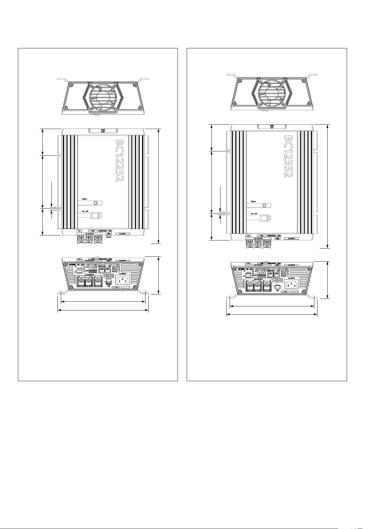
15 Hoofdafmetingen Principal dimensions Hauptabmessungen
”)
”)
8
/
3
8
/
3
”)60 (2
4
/
3
120 (4
”) 60 (2
8
/
3
”)
16
/
”)
4
/
1
3
6 (
”) 259 (10
16
/
5
84 (3
190 (7 1/2”)
205 (8 1/16”)
”)60 (2
2
/
1
140 (5
”) 60 (2
8
/
3
”)
4
/
1
279 (11”)
6 (
”)
16
/
5
84 (3
190 (7 1/2”)
205 (8 1/16”)
46 090141.01
BC12151
BC12252
BC24122 BC12352
vetus® Battery chargers BC12151, BC12252, BC12352, BC12503, BC12803, BC24122, BC24253, BC24403

Dimensions principales Dimensiones principales Dimensioni principali
”)
8
/
”)
8
/
3
3
”)60 (2
8
/
7
149 (5
1
”) 60 (2
8
/
3
”)
4
/
6 (
222 (8 3/4”)
237 (9 5/16”)
”)
16
/
5
”) 288 (11
16
/
9
90 (3
”)60 (2
16
/
7
189 (7
”) 60 (2
8
/
3
”)
16
/
15
”)
4
/
1
6 (
”) 328 (12
16
/
9
90 (3
222 (8 3/4”)
237 (9 5/16”)
BC12503 BC24253 BC12803 BC24403
vetus® Battery chargers BC12151, BC12252, BC12352, BC12503, BC12803, BC24122, BC24253, BC24403
090141.01 47

vetus b.v.
Printed in Taiwan
090141.01 2017-10
FOKKERSTRAAT 571 - 3125 BD SCHIEDAM - HOLLAND
TEL.: +31 0(0)88 4884700 - sales@vetus.nl - www.vetus.com
 Loading...