

Vetta V100HR User Manual
CONTENTS
ENGLISH
INTRODUCTION
WARNINGS & CAUTIONS
V100HR ILLUSTRATIONS
HEAD UNIT
COMPONENT ILLUSTRATIONS
BUTTON FUNCTIONS
SETUP MODE
OPERATING MODE
V100HR SCREEN DISPLAY SEQUENCE:
BI-LEVEL MEMORY
V100HR PRIMARY FUNCTIONS
UPPER SCREEN MODES
Speed, Trip Distance, Ride Time, Total Time
Average Speed, Maximum Speed
Speed*, Cadence*
LOWER SCREEN MODES
Heart Rate, Percent Of Maximum HR
Clock, Odometer, Stopwatch,
Intermediate Distance
Dual Bike Memory, Heart Rate Reading
V100HR SECONDARY FUNCTIONS
& FEATURES
Service Timer, Average Cadence*,
Maximum Cadence*
Low Battery Alert, Speed Comparator
Freeze Frame Memory
Heart Rate Memory Storage & Recall
AUTO START
SLEEP MODE
1.
2.
3.
4.
5.
6.
7.
3
4
5
6
8
9
9
11
12
13
13
14
15
16
17
18
19
20
20

8.
9.
10.
11.
12.
13.
14.
15.
21
21
21
22
26
27
28
28
40
44
45
46
49
50
51
52
54
55
56
57
57
59
60
AUDIBLE & VISUAL ALARMS
RIDE DATA RESET
ALL CLEAR TOTAL RESET
TARGET ZONE & FITNESS TRAINING
BATTERY INSTALLATION
HEAD UNIT
WL WIRELESS SPEED TRANSMITTER
HEART RATE TRANSMITTER
SETUP MODE & PROGRAMMING
INSTALLATION
WIRED MODEL INSTALLATION
Speed Sensor & Magnet
Mounting Bracket
Head Unit
WIRELESS MODEL INSTALLATION
Speed Transmitter & Magnet
Active Mount
Head Unit
INSTALLATION TESTS
ATTACHING YOUR HEART MONITOR
TROUBLESHOOTING
PROBLEM/ITEMS TO CHECK/SOLUTION: CYCLING
PROBLEM/ITEMS TO CHECK/SOLUTION: HEART
CARE & MAINTENANCE
BATTERY REPLACEMENT
TECHNICAL SPECIFICATIONS
WARRANTY POLICY
REQIREMENTS FOR WARRANTY SERVICING
ITEMS TO BE INCLUDED IN RETURNS

INTRODUCTION
Thank you for purchasing a Vetta V100HR cycle computer and
heart rate monitor. The V100 series computers represent the latest
evolution in Vetta's computer line and are designed for cycling
enthusiasts and multi-sport athletes alike. In particular, the V100HR
model offers a wide range of unique features and functions such as
Dual Bike Memory, Intermediate Distance and Stopwatch readings,
multiple Heart Rate functions and a Service Timer. For people
interested in fitness, the V100HR offers Target Zone Heart Rate
functions that will increase the effectiveness of your workout by
monitoring and quantifying your results every step of the way. For
most individuals, as little as 20 minutes in your target heart rate
zone each session is enough to achieve substantial health
improvements. Please take time to familiarize yourself with all the
functions of the V100HR model so you can take full advantage of
its programs. And don't forget to store this manual in a safe place
for future reference!

WARNINGS & CAUTIONS
Vetta cycle computers are sophisticated electronic instruments.
Vetta recommends that this product be installed by a qualified
bicycle retailer. Failure to read these instructions and/or
improper installation of this device may void the warranty. If in
doubt about any part of the installation or operation of this
product, please consult your local bicycle retailer for
clarification.
The head unit and chest transmitter are water resistant and
sealed to withstand wet weather conditions. However, do not
deliberately place them in water.
Avoid leaving the head unit exposed to extremely hot weather
conditions.
Overexertion can cause serious injury, including heart attacks.
Some individuals cannot safely elevate their heart rate to the
levels of typically used heart rate training zones. No one should
begin an exercise program without first obtaining medical
clearance, especially if there is a personal or family history of
heart disease, high blood pressure, or if you are over age 40,
have diabetes, high cholesterol, smoke cigarettes, are
overweight or are taking certain medications. Stop exercising
and seek medical attention if you notice signs of overexertion
or heart problems, such as pain or pressure in the left or midchest area or left neck, shoulder or arm, light-headedness, cold
sweat, unusual paleness or fainting. Also note that the signals
used by this monitor may interfere with a pacemaker or other
implanted devices. Consult the manufacturer of the implant
device and/or your physician prior to using this monitor.
Vetta encourages you to ride safely. Wear a helmet every time
you ride, use front and rear lights at night, and always keep
your eyes on the road ahead of you.
•
•
•
•
•
A
B
C
D
3
4
1
6
5
13
8
2
10
11
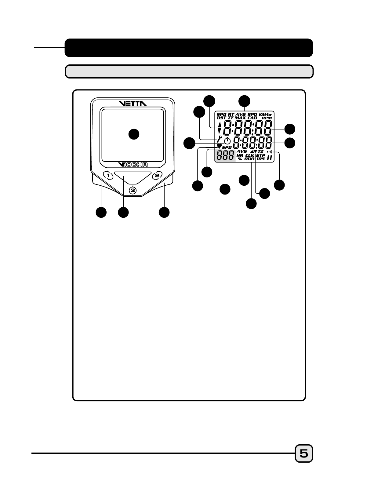
V100HR ILLUSTRATIONS
HEAD UNIT: FRONT
Upper Display
Lower Display
Audible Alarm Icon
Lower Screen Symbols
Upper and Lower Target Zone Symbols
Sub-Display Average HR Symbol
Sub-Display Speed Symbol
Heart Rate/Speed Sub-Display
Heart Rate Icon
Stopwatch Icon
Service Timer Icon
Speed Comparator Symbol
Upper Screen Symbols
1
2
3
4
5
6
7
8
9
10
11
12
Main Display
Button #1 (Left)
Button #2 (Right)
Button #3 (Center)
B
C
D
7
9
12
A
A
B
C
C
A
B
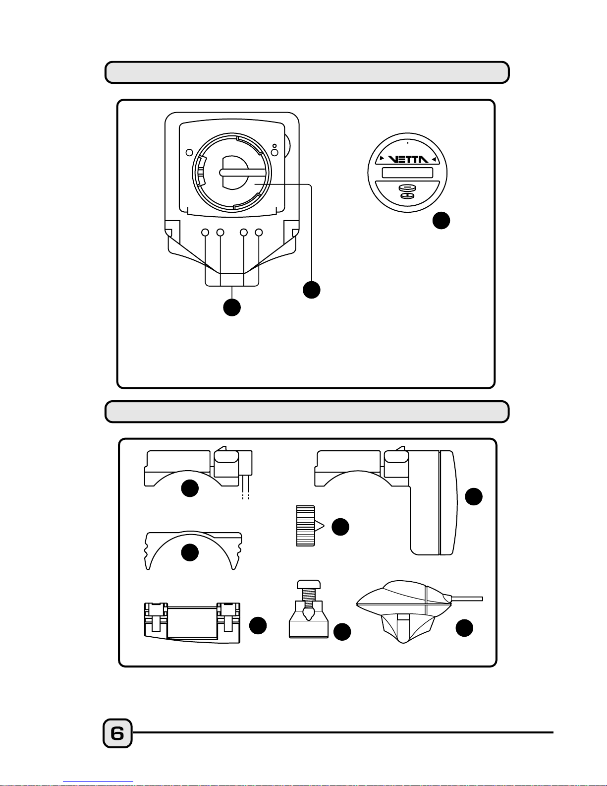
COMPONENT ILLUSTRATIONS
HEAD UNIT: REAR
Contact Pins
Battery Compartment
Battery Cover
B
A
G
F
D
C
E
O
P
E
N
C
L
O
S
E
C
R
2
0
3
2

A
B
C
D
E
F
G
H
I
J
K
L
M
N
O
P
K
N
M
O
J
I
I
L
C
R
2
0
3
2
3
V
O
L
T
L
I
T
H
I
U
M
C
E
L
L
Wired Mounting Bracket
Mounting Bracket Pad
Riser Handle Bar Bracket Pad
(You may choose B or C
according to the style of your bicycle handlebar.)
Spoke Magnet
Spacer
Wired Speed Sensor
Wireless Active Mount
WL Wireless Speed Transmitter
Transmitter Mounting Pad
Wired Cadence Sensor*
Cadence Magnet*
CR2032 3V Battery
Zip Ties
Wire Securing Tape
A23 12V Battery
WL2X Wireless Cadence Transmitter*
Chest Transmitter w/Strap
*(optional)
P
H
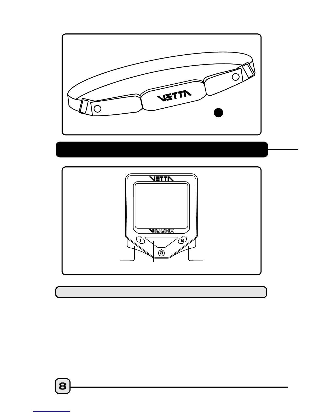
BUTTON FUNCTIONS
Sets digits or units and advances to the next item
or screen.
Advances digits and toggles through units.
Hold for fast advance.
Has no function in Initial Setup.
Button #1
Button #2
Button #3
SETUP MODE
Button #1
Button #3
Button #2
Q

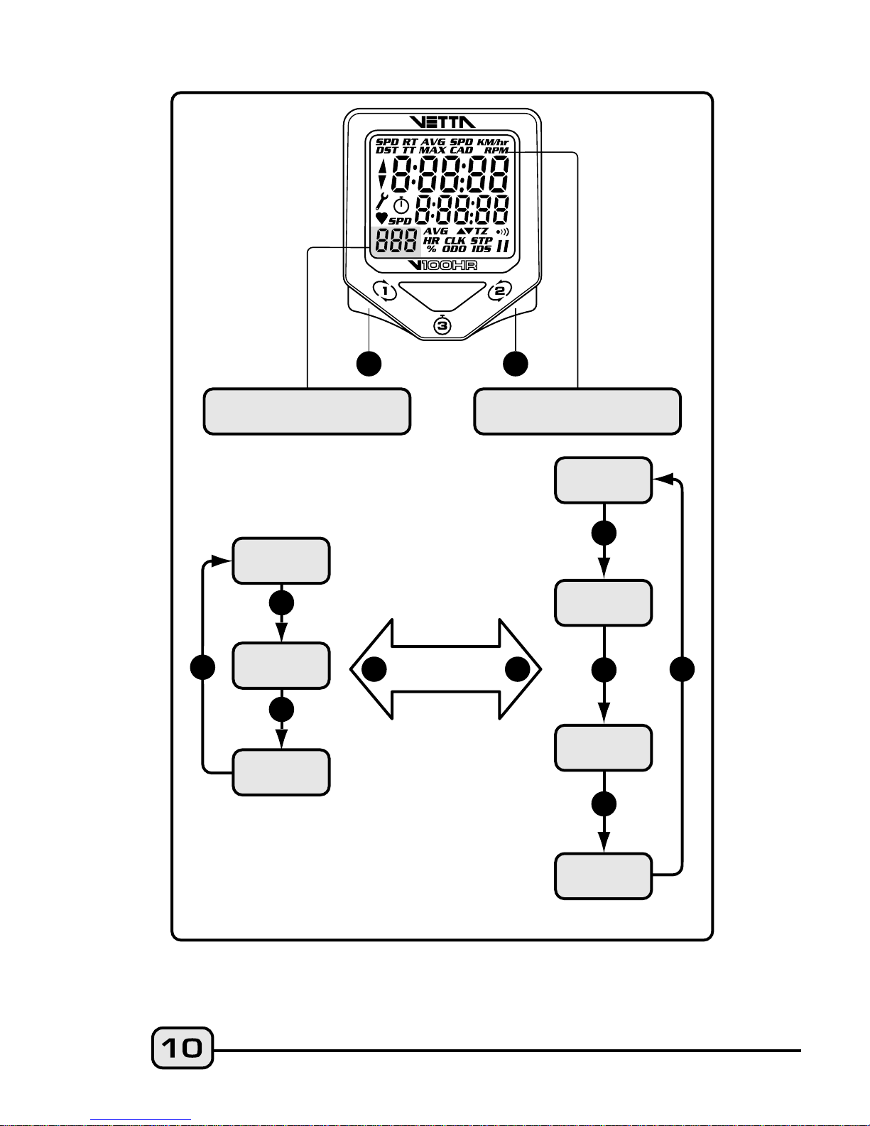
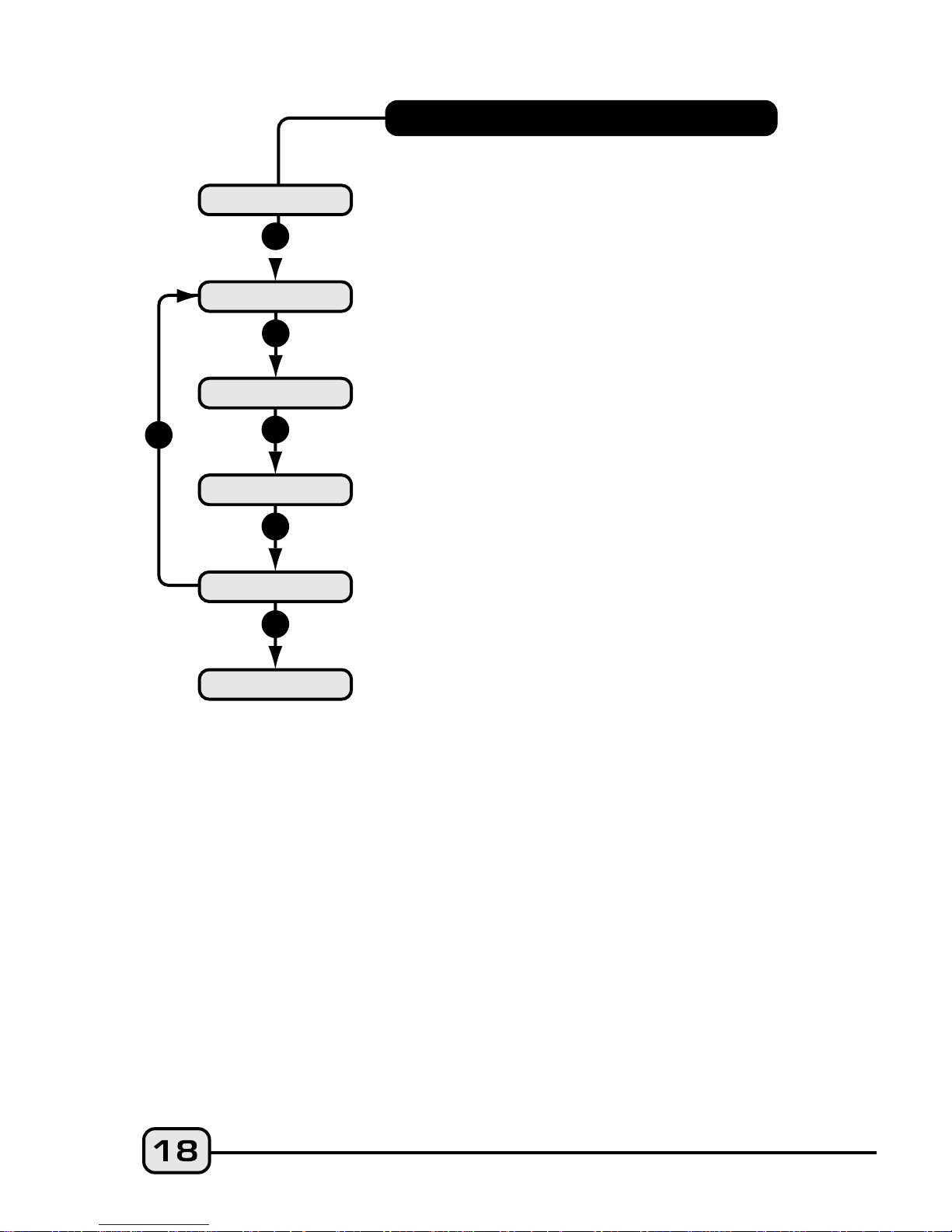
The V100 series computers are programmed with a Bi-Level Memory
which returns to the last screen function accessed between the
upper and lower screen modes. See illustration for this sequence
and instructions on how to advance from one screen to the next.
V100HR SCREEN DISPLAY
SEQUENCE: BI-LEVEL MEMORY
Scrolls through lower level screen symbols and
Freeze Frame display screens. Hold 2 seconds in
HR/% screen mode to display HR data from Heart
Rate Memory Storage and Recall. Hold 2 seconds in
SPD/CAD* screen to display Average and Maximum
Cadence.
*(Optional)
Scrolls through upper level screen symbols and
Heart Rate Memory Storage and Recall screens.
Press and hold 2 seconds in any primary screen
mode to activate Freeze Frame memory. Resets RT
to zero for Service Timer.
Starts and stops the timers and Stopwatch and is
used to reset timers, Stopwatch and other ride data
to zero. Exits Normal Operating Mode (NOM) Setup
and advances to NOM System Check and either the
SPD/DST or HR/% screen mode.
With RT/TT timers turned OFF, hold both buttons
simultaneously for 2 seconds in the SPD/DST
primary screen to enter NOM Setup for bicycle
functions. Hold simultaneously for 2 seconds in the
HR/% screen mode to enter NOM Setup for heart
rate functions.
Button #1
Button #2
Button #3
Buttons #1 &
#2
OPERATING MODE
1
2
LOWER SCREEN
MODES
UPPER SCREEN
MODES
1
STP
IDS
CLK
ODO
1
HR
%
2
2
2
RT
TT
AVG
MAX
SPD
DST
BI-LEVEL
MEMORY
1
2
SPD*
CAD
2
*(Optional)
1
RT
TT
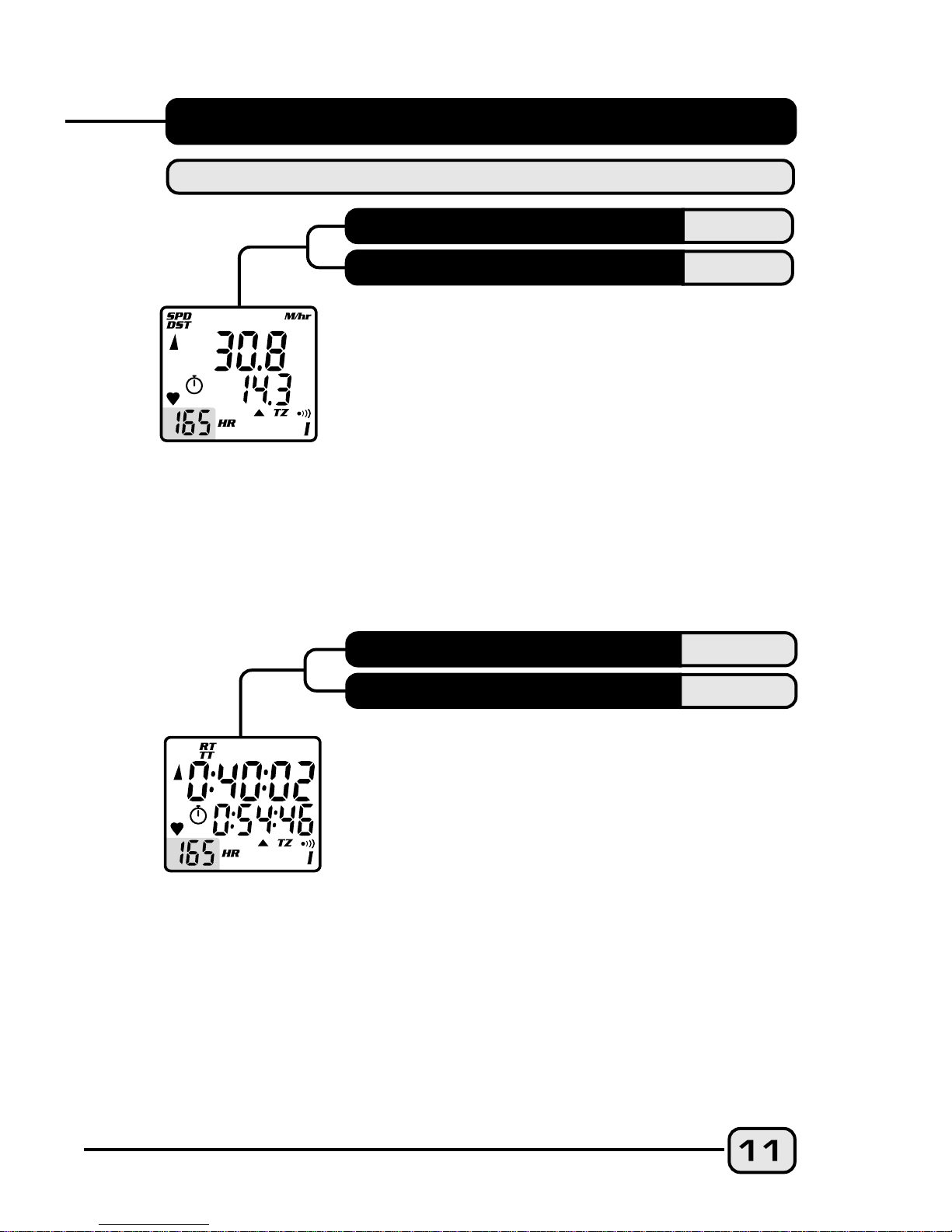
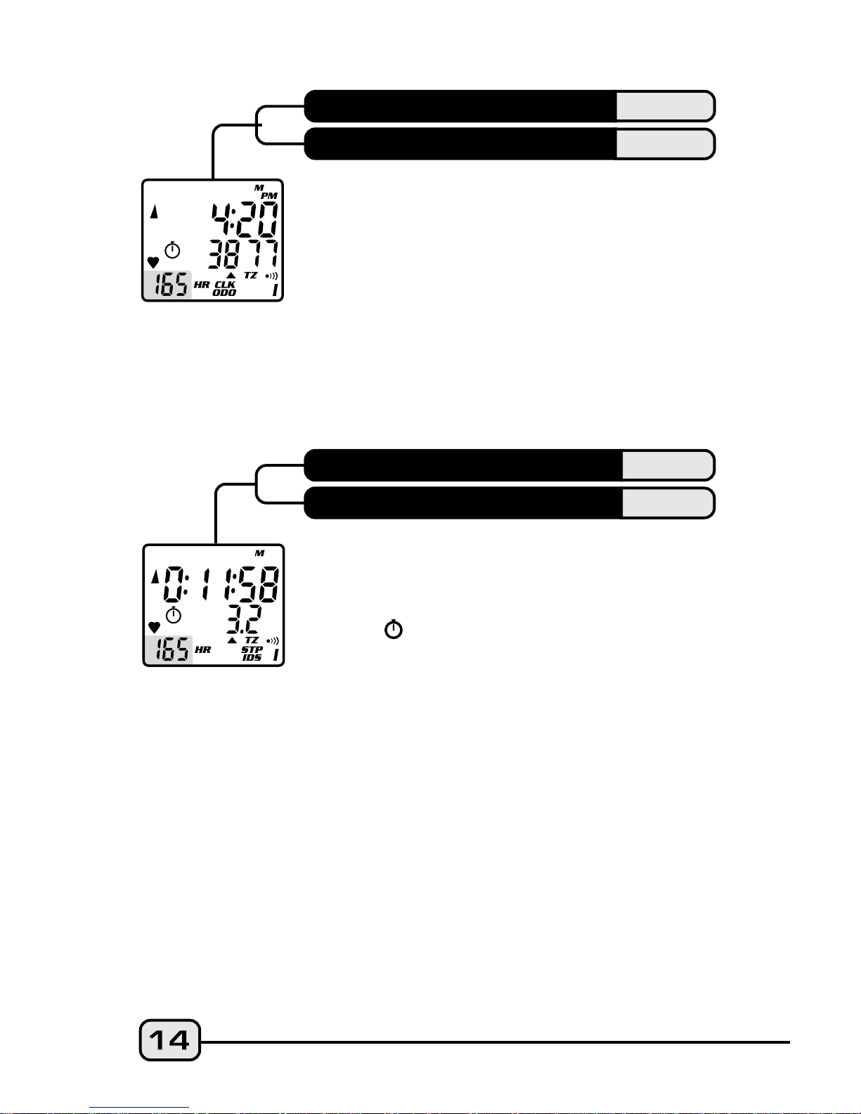
SPD displays the current Speed and is
updated continuously. DST displays current
Trip Distance and automatically resets after
the maximum trip distance (999.9) is
achieved. Trip Distance is displayed in the
SPD/DST screen mode and starts
automatically when the wheel rotates and TT
timer is active. Reset DST to zero by
pressing Button #3 for 2 seconds with the
timers turned off in any screen mode
except SPD/IDS.
SPD
DST
V100HR PRIMARY FUNCTIONS
UPPER SCREEN MODES
SPEED
TRIP DISTANCE
RIDE TIME
TOTAL TIME
Ride Time and Total Time are shown
simultaneously. Ride Time (RT) measures actual
riding time and starts automatically when the
timers are set to "0:00:00" and the wheel
rotates. Total Time (TT) shows the total elapsed
trip time from start to finish. Like RT, TT starts
automatically when the wheel rotates ONLY
when the timers are set to "0:00:00", or it can be
started manually by pressing Button #3 in the
RT/TT screen mode ONLY. TT can only be
stopped manually by momentarily pressing
Button #3 in the RT/TT screen mode at the end
AVG
MAX
of a ride. To reset both RT and TT to zero, turn the timers off and
press Button #3 for at least 2 seconds. Note: Whenever TT is
activated, the stopwatch icon appears; otherwise it does not
appear. The TT Timer must be active in order for the RT Timer to
accumulate Ride Time and for the computer to calculate current
ride and heart rate memory data.
CAUTION: If RT and TT timers are not 0:00:00 and you have
stopped them manually, then they MUST be restarted
manually by pressing Button #3 in the RT/TT mode. If not,
the computer will not record speed or other ride or heart rate
memory data. RT and TT Timers can be manually activated or
deactivated only from the RT/TT screen mode.
RIDING TIP: If the bike is in motion and Button #3 is held down
in the RT/TT screen mode with the timers deactivated, the ride
timers reset to 0:00:00. When Button #3 is released, both RT and TT
will start with the next wheel input. This is a good way to begin
timing a race or training ride with a rolling start.
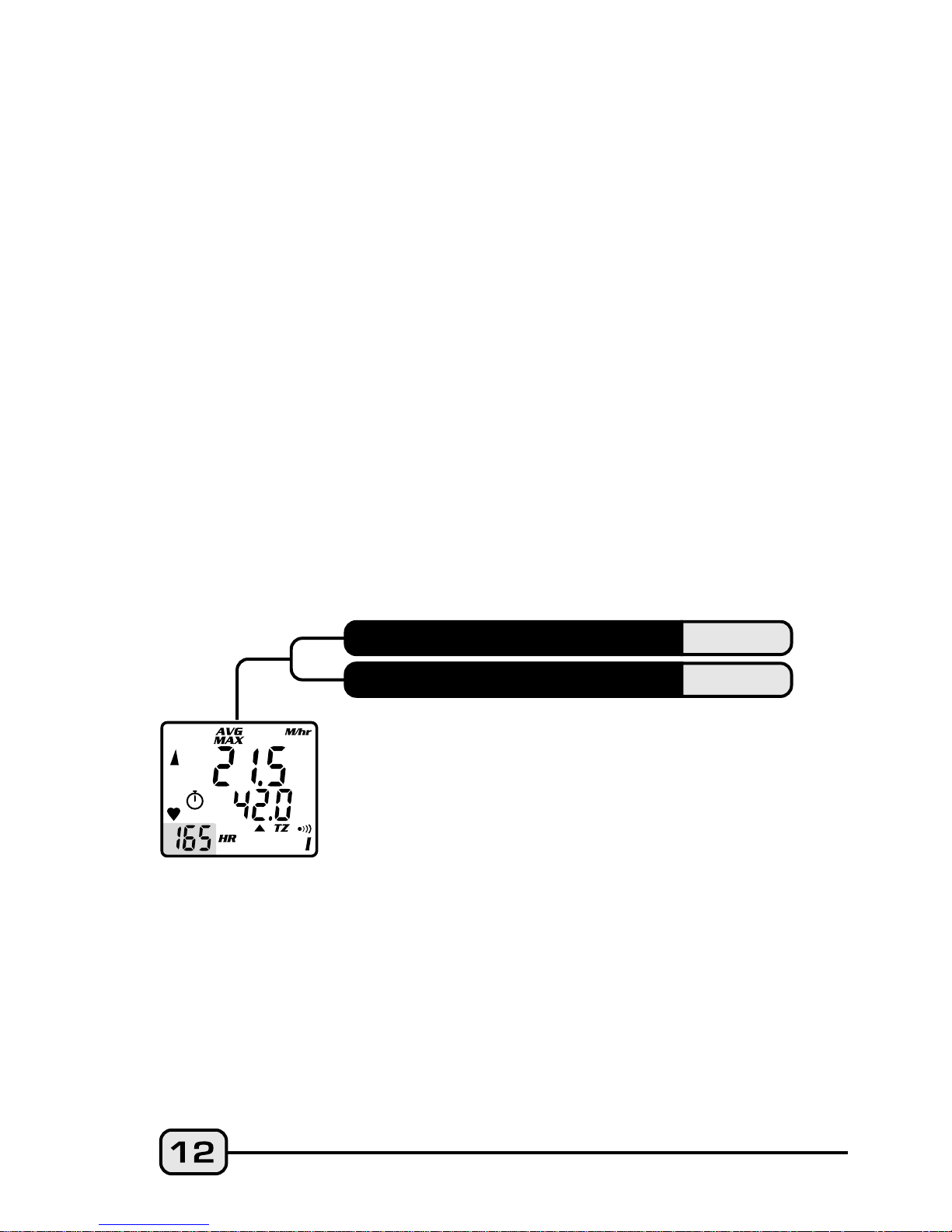
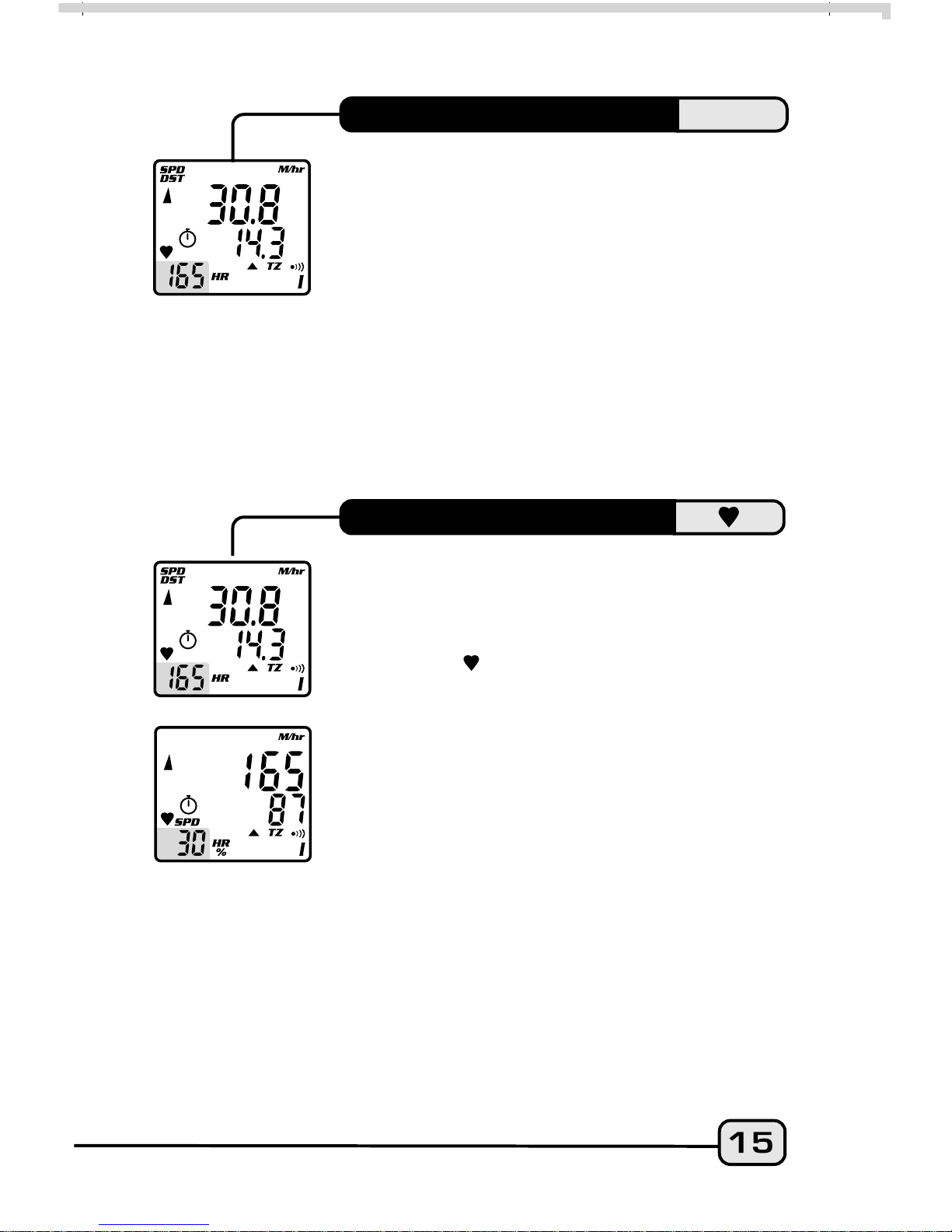
Average and Maximum Speed readings are
displayed simultaneously in the AVG/MAX
screen mode. Average Speed is updated every
0.1 miles or Km traveled. Reset both to zero
by pressing Button #3 for 2 seconds with
timers turned off in any screen mode
except STP/IDS.
AVERAGE SPEED
MAXIMUM SPEED
SPD
CAD
HR
%
LOWER SCREEN MODES
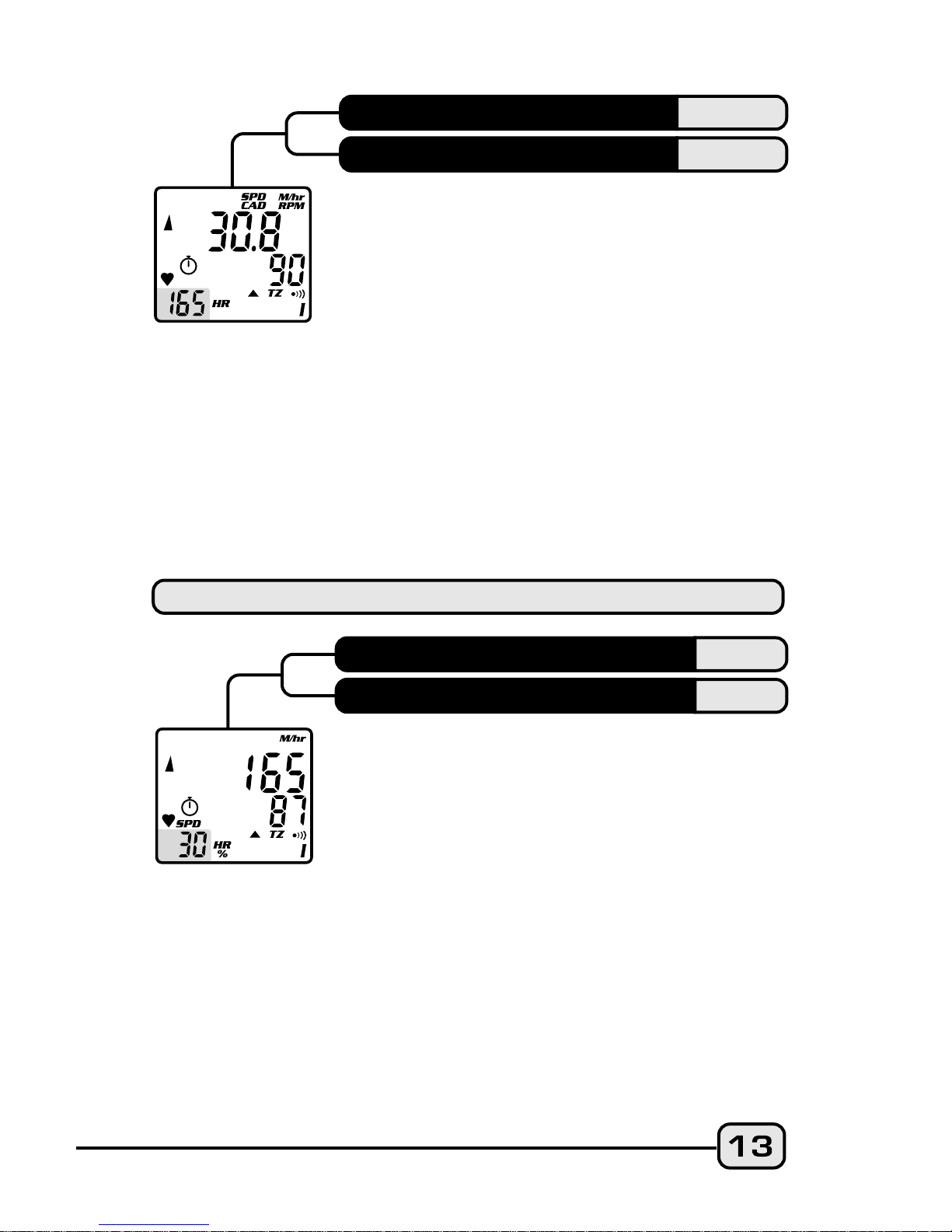
When installed, the Cadence kit measures and
displays pedal Cadence in Revolutions Per
Minute (RPM). The SPD/CAD screen function
letters appear ONLY when the Cadence
hardware is installed and a Cadence signal
received by the head unit. After a current ride
data reset, (Button #3 for 2 seconds with
timers off) the function letters will disappear,
but they will will come back on with the next
Cadence input. Note: RT and TT timers
MUST be activated in order for Speed and
Cadence to function.
* (Optional)
SPEED*
CADENCE*
Displays current Heart Rate in beats per minute
on the upper line and the percentage of your
preset maximum heart rate on the lower line.
The heart icon will blink steadily when the
head unit is receiving and recording a heart
rate signal from the transmitter. This icon
disappears from the display when no heart rate
signal is received.
HEART RATE
PERCENT OF MAXIMUM HR
STP
IDS
The independent Stopwatch is operated by
Button #3 in the STP/IDS screen mode. STP
operates in conjunction with the RT/TT
timers ( icon must be visible) and can be
started or stopped by pressing Button #3. The
Intermediate Distance function tracks an
intermediate distance within a ride. IDS does
not affect overall Trip Distance or current ride
data, but it operates the same as the DST
function. In the STP/IDS screen mode with
timers active, press Button #3 to start
Stopwatch and IDS functions; press Button #3
again to stop functions and freeze data for
review. Reset both Stopwatch and IDS to zero
by pressing Button #3 for 2 seconds.
STOPWATCH
INTERMEDIATE DISTANCE
CLK
ODO
The time is displayed in the CLK/ODO screen
mode and features a user selectable 12 or 24
hour format. The Odometer displays
cumulative distance until an All Clear Total
Reset is performed, the battery is changed*,
or the ride distance exceeds the maximum
limit, after which the Odometer will
automatically reset to zero. *Note:
Odometer reading can be reinstalled by
user after a battery change.
CLOCK
ODOMETER
I
II
DUAL BIKE MEMORY
The V100HR can be calibrated for two bicycles.
It will store separate Wheel Size, Service Timer,
Odometer, Age and Heart Rate Target Zone
settings, as well as different formats for Time,
Speed and Distance. The current bike number
(I or II) is always displayed in the lower right
corner of the screen. To switch the computer
quickly from Bike I to Bike II, go to the first
screen in the Normal Operating Mode Setup
program for cycling. (See SETUP section
below for details.)
HEART RATE READING
The V100HR monitor displays Heart Rate in
the lower left screen segment. The range is
40 to 240 beats per minute, and the blinking
heart icon ( ) displays as long as a signal is
being received. When the monitor is toggled
to the HR/% screen mode (Button #1),
current Heart Rate is displayed on the upper
line and the Percent of Maximum HR on the
lower line. Current Speed is then displayed
in this small screen segment and the letters
"SPD" appear immediately above it. (see
screen illustrations).
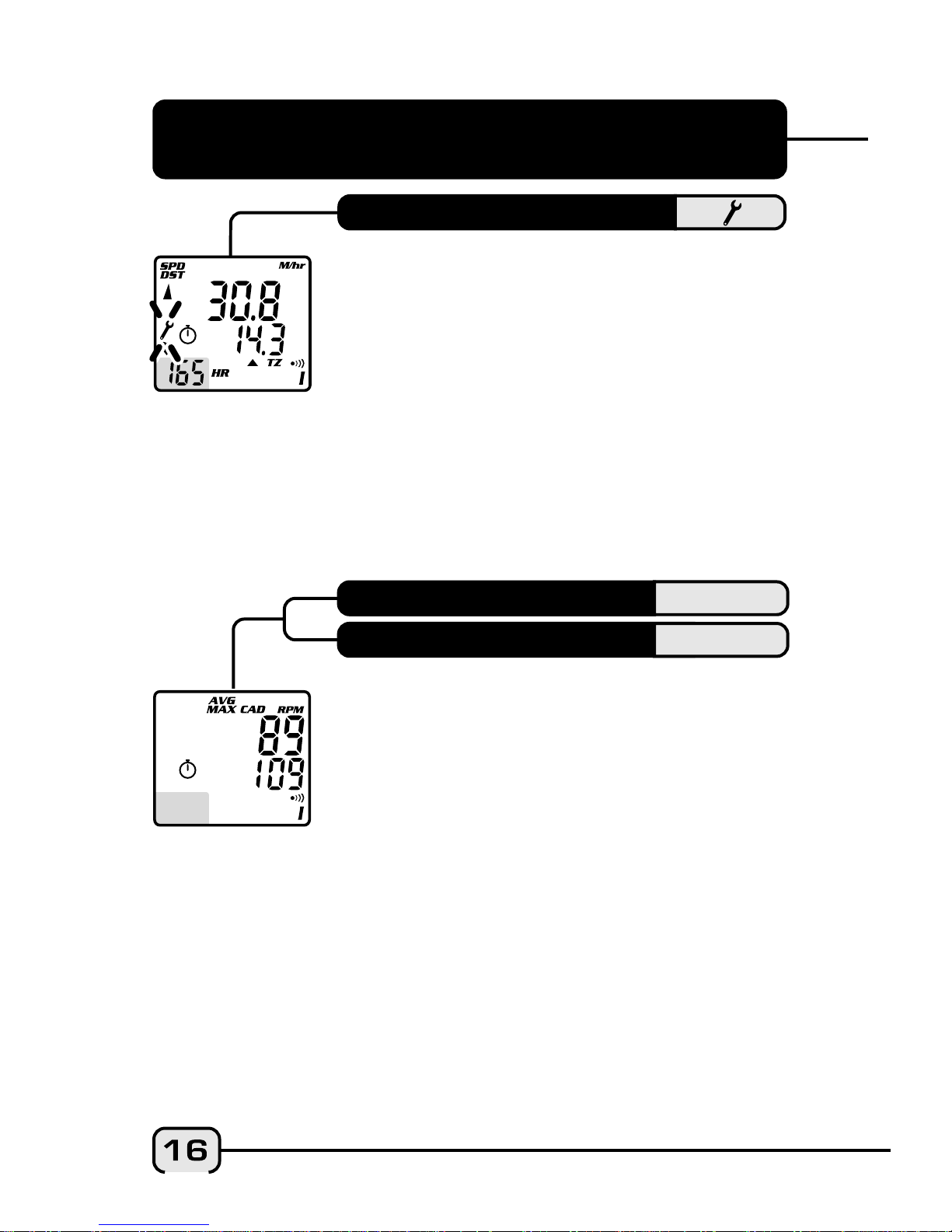
When the V100HR is attached to a cadence
mount, it displays both Average and
Maximum Cadence in a secondary screen.
Press and hold Button #1 in the SPD/CAD
screen mode for 2 seconds. Average and
Maximum Cadence appear on the upper and
lower lines respectively. Press Button #1 again
to return to the primary SPD/CAD screen.
*(Optional)
AVERAGE CADENCE*
AVG CAD
MAXIMUM CADENCE*
MAX CAD
V100HR SECONDARY FUNCTIONS
& FEATURES
Alerts rider when Ride Time reaches a preset
limit for a maintenance check on the bike or
any main component. Suspension forks, rear
shocks, chains, etc. require service at specific
time intervals set by manufacturers. Vetta's
Service Timer allows the rider to preset an
exact number of riding hours during Setup,
then signals (slow, flashing wrench icon) when
the service time limit has been reached. (See
SETUP section below for details.)
SERVICE TIMER
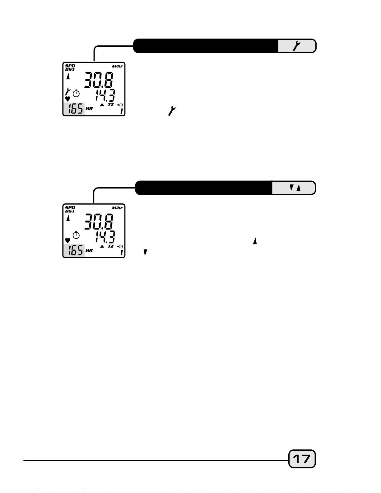
The Speed Comparator symbols on the left
side of the display screen indicate whether
current Speed is above or below current
Average Speed. A positive ( ) or negative
( ) symbol appears in the upper left part of
the screen in all primary screen modes. The
Speed Comparator symbols do not appear if
Speed (SPD) and Average Speed (AVG) are the
same.
SPEED COMPARATOR
The V100HR Service Timer icon has been
programmed to signal low battery power in
the head unit. When the battery runs low
and needs to be replaced, the Service Timer
icon ( ) will illuminate and stay "on" (no
blinking). Replace the head unit battery as
soon as possible. Rapid blinking of the
Service icon indicates both low battery
power and expiration of the preset service
time interval.
LOW BATTERY ALERT
Freezes ride data from 4 primary
screens for review at any point during a
race or training ride. To activate Freeze
Frame, press and hold Button #2 for 2
seconds in any primary screen mode.
The screen will flash to indicate it has
been frozen. The computer will
continue to record ride data. Advance
through the frozen screens by pressing
Button #1 repeatedly. Press Button #2 to
cancel Freeze Frame and return to the
previous screen mode.
Note: If Ride Time/Total Time (RT/TT) is
not running at the time Freeze Frame is
activated (Button #2 for 2 seconds),
previously frozen ride data will be
displayed. At the end of the ride, user
can view both "end-of-ride" data (by
stopping the timers and toggling
through the primary screens) and the
last Freeze Frame data screens recorded
(by activating Freeze Frame with the
RT/TT timers turned off).
FREEZE FRAME MEMORY
SPD/DST
RT/TT
AVG/MAX
SPD/DST
2
1
1
SPD/DST
2
HR/%
1
1
 Loading...