

Vetta V100A User Manual
CONTENTS
ENGLISH
INTRODUCTION
WARNINGS & CAUTIONS
V100A ILLUSTRATIONS
HEAD UNIT
COMPONENT ILLUSTRATIONS
BUTTON FUNCTIONS
SETUP MODE
OPERATING MODE
V100A SCREEN DISPLAY SEQUENCE:
BI-LEVEL MEMORY
V100A PRIMARY FUNCTIONS
UPPER SCREEN MODES
Speed,Trip Distance, Ride Time,Total Time
Average Speed, Maximum Speed
Speed*, Cadence*
LOWER SCREEN MODES
Altitude, Percent Grade
Total altitude, Maximum Altitude,
Clock, Odometer
Speed, Temperature, Stopwatch,
Intermediate Distance
Stopwatch, Intermediate Altitude
Dual Bike Memory
V100A SECONDARY FUNCTIONS
& FEATURES
Maximum & Minimum Temperature
Average Cadence*, Maximum Cadence*,
Maximum Percent Grade-Climbing,
Maximum Percent Grade-Descending
1.
2.
3.
4.
5.
6.
7.
3
3
4
5
7
7
8
10
11
12
12
13
14
15
16
16
17

8.
9.
10.
11.
12.
13.
14.
18
19
20
20
21
21
22
23
24
36
41
44
45
46
49
51
52
53
55
57
58
Service Timer, Low Battery Alert, Speed Comparator
Freeze Frame Memory
AUTO START
SLEEP MODE
RIDE DATA RESET
ALL CLEAR TOTAL RESET
BATTERY INSTALLATION
HEAD UNIT
WL WIRELESS SPEED TRANSMITTER
SETUP MODE & PROGRAMMING
P
RE-RIDE ALTIMETER CALIBRATION SETUP
INSTALLATION
WIRED MODEL INSTALLATION
Speed Sensor & Magnet
Mounting Bracket
Head Unit
WIRELESS MODEL INSTALLATION
Speed Transmitter & Magnet
Active Mount
Head Unit
INSTALLATION TESTS
TROUBLESHOOTING
PROBLEM/ITEMS TO CHECK/SOLUTION
TECHNICAL SPECIFICATIONS
WARRANTY POLICY
REQUIREMENTS FOR WARRANTY SERVICING
ITEMS TO BE INCLUDED IN RETURNS

INTRODUCTION
WARNINGS & CAUTIONS
Thank you for purchasing a Vetta V100A cycle computer. The
V100 series computers represent the latest evolution in Vetta's
computer line and are designed for cycling enthusiasts and
competitive cyclists alike. In particular, the V100A model offers a
wide range of unique features and functions such as Altitude,
Temperature, Dual Bike Memory, Intermediate Altitude and
Distance, Stopwatch readings and a Service Timer. Please take
time to familiarize yourself with all the functions of the V100A
model so you can take full advantage of its programs. And don't
forget to store this manual in a safe place for future reference!
Vetta cycle computers are sophisticated electronic instruments.
Vetta recommends that this product be installed only by a
qualified bicycle retailer. Failure to read these instructions
and/or improper installation of this device may void the
warranty. If in doubt about any aspect of the installation or
operation of this product, consult your local bicycle retailer for
clarification.
The V100A cycle computer is a general indicator of altitude; it
is not suitable or intended for any use other than cycling.
Elevation and Percent Grade values displayed by the V100A
altimeter may be subject to slight fluctuations due to changes in
barometric pressure readings taken by the unit's pressure sensor.
Such changes, attributed primarily to variations in temperature
and weather, may affect the accuracy of this instrument.
The head unit is water resistant and sealed to withstand wet
weather conditions. However, do not deliberately place it in
water.
Avoid leaving the head unit exposed to extremely hot or cold
weather conditions.
•
•
•
•
A
A
B
C
D
2
8
3
1
6
5
9
7
4
Vetta encourages you to ride safely. Wear a helmet every time
you ride, use front and rear lights at night, and always keep
your eyes on the road ahead of you.
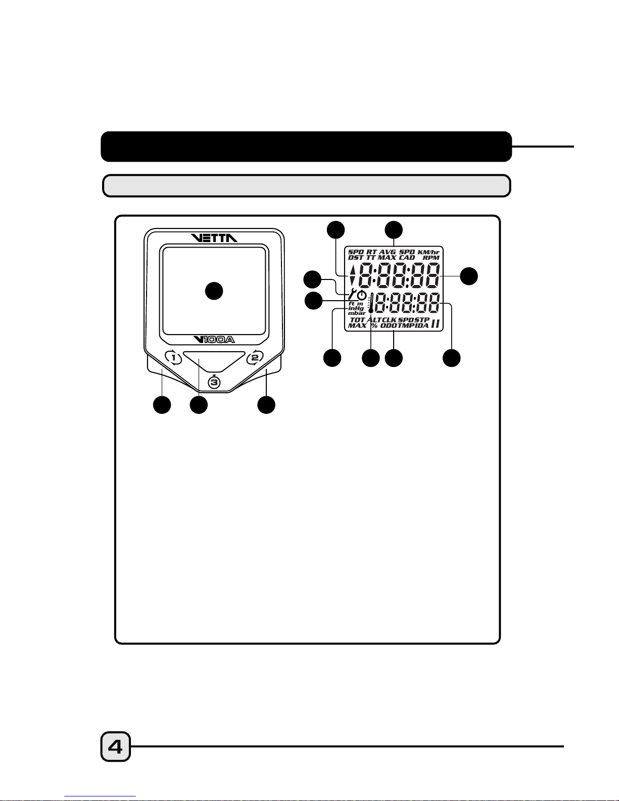
V100A ILLUSTRATIONS
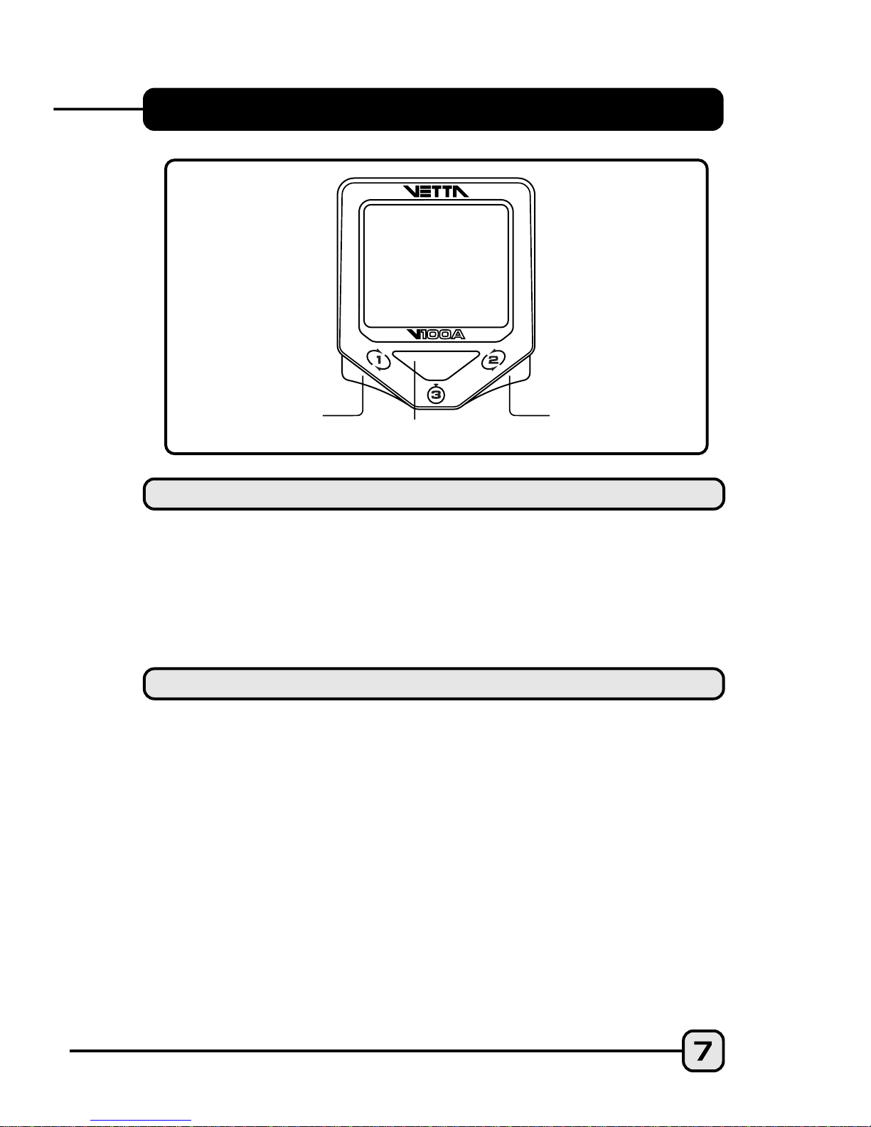
HEAD UNIT: FRONT
Upper Display
Lower Display
Lower Screen Symbols
Temperature Icon
Altimeter and Barometric Pressure Unit Symbols
Stopwatch Icon
Service Timer Icon
Speed Comparator Symbol
Upper Screen Symbols
1
2
3
4
5
6
7
8
9
Main Display
Button #1 (Left)
Button #2 (Right)
Button #3 (Center)
B
C
D
•
A
B
C
A
B
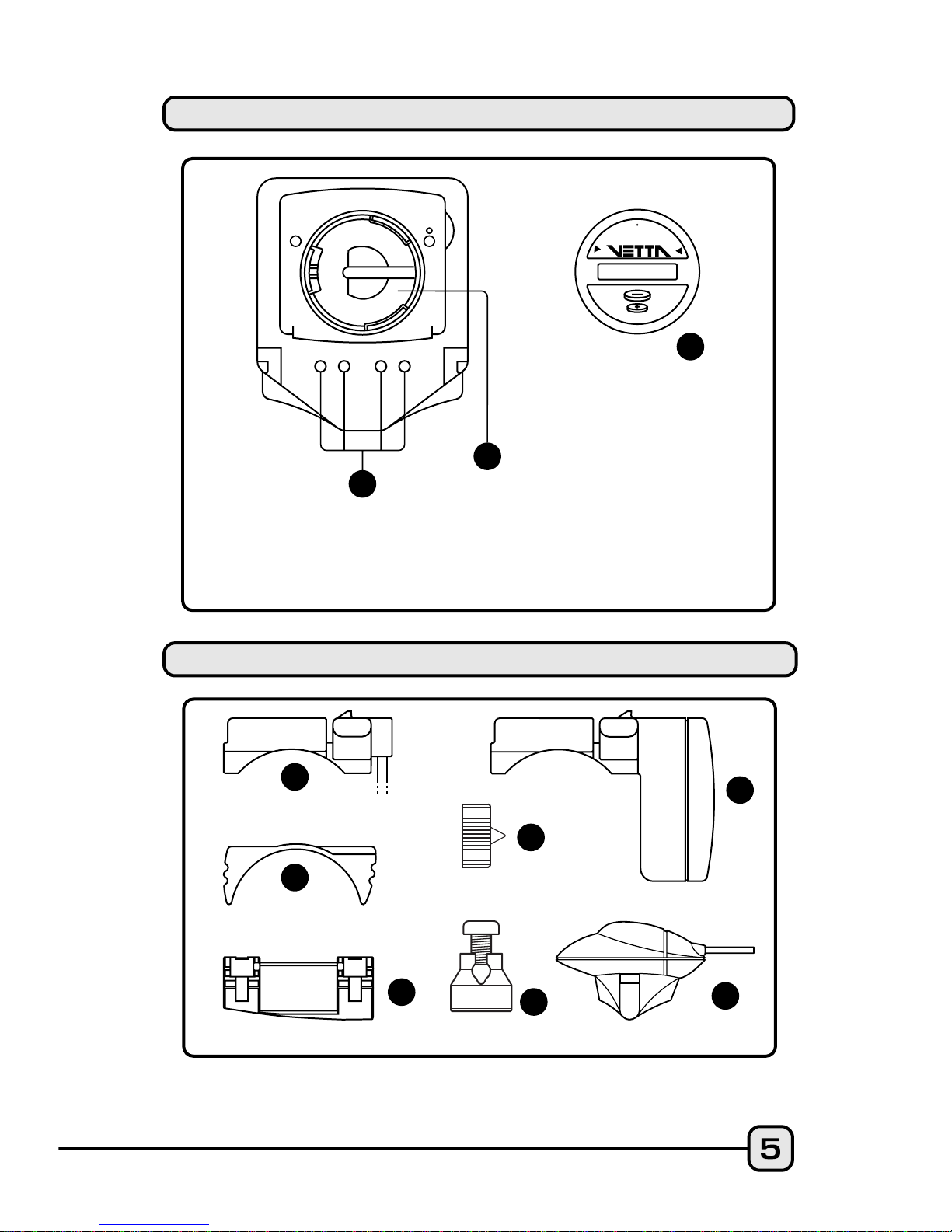
COMPONENT ILLUSTRATIONS
HEAD UNIT: REAR
Contact Pins
Battery Compartment
Battery Cover
B
A
G
F
D
C
E
C
O
P
E
N
C
L
O
S
E
C
R
2
0
3
2
A
B
C
D
E
F
G
H
I
J
K
L
M
N
O
P
K
N
M
O
J
I
L
C
R
2
0
3
2
3
V
O
L
T
L
I
T
H
I
U
M
C
E
L
L
Wired Mounting Bracket
Mounting Bracket Pad
Riser Handle Bar Bracket Pad
(You may choose B or C
according to the style of your bicycle handlebar.)
Spoke Magnet
Spacer
Wired Speed Sensor
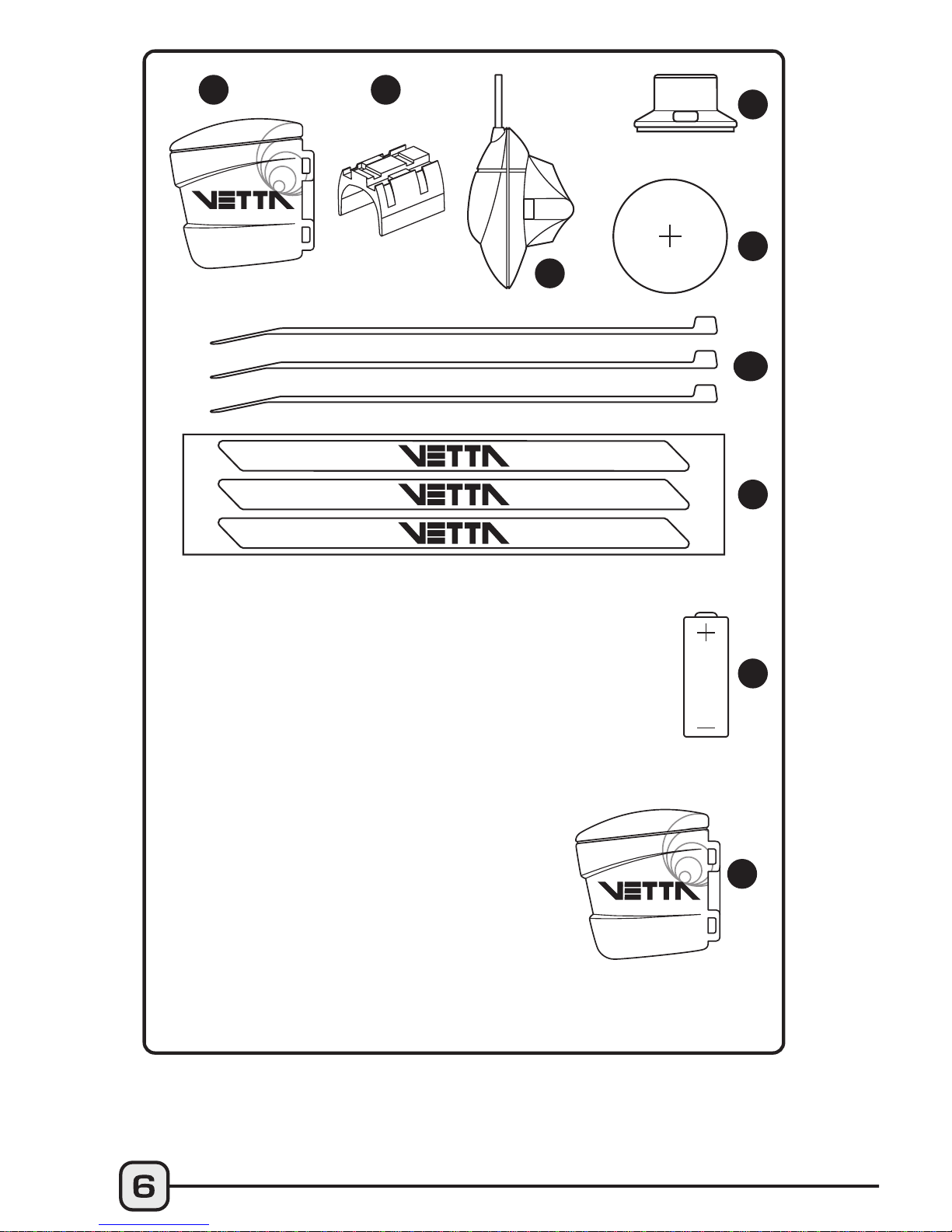
Wireless Active Mount
WL Wireless Speed Transmitter
Transmitter Mounting Pad
Wired Cadence Sensor*
Cadence Magnet*
CR2032 3V Battery
Zip Ties
Wire Securing Tape
A23 12V Battery
WL2X Wireless Cadence Transmitter*
*(optional)
P
H
BUTTON FUNCTIONS
Sets digits or units and advances to the next item or
screen.
Advances digits and toggles through units. Hold for
fast advance.
Has no function in Initial Setup.
Button #1
Button #2
Button #3
SETUP MODE
Scrolls through lower level screen symbols and
Freeze Frame display screens.
Hold 2 seconds in Temperature mode (SPD/TMP)
to display Maximum and Minimum Temperature.
Hold 2 seconds in SPD/CAD* screen to display
Average and Maximum Cadence.
Hold 2 seconds in ALT/% screen mode to display
Max % uphill grade and Max % downhill grade.
Hold 2 seconds in STP/ID screen mode to switch to
STP/IA screen mode, or hold 2 seconds in STP/IA
screen mode to switch to STP/ID screen mode.
*(optional)
Button #1
NORMAL OPERATING MODE
Button #1
Button #3
Button #2
•
•
•
•

The V100 series computers are programmed with a Bi-Level
Memory which returns to the last screen function accessed
between the upper and lower screen modes. See illustration for
this sequence and instructions on how to advance from one
screen to the next.
V100A SCREEN DISPLAY SEQUENCE:
BI-LEVEL MEMORY
Scrolls through upper level screen symbols. Press
and hold 2 seconds in any primary screen mode
to activate Freeze Frame memory. Resets RT to
zero for Service Timer.
Starts and stops the timers and Stopwatch and is
used to reset timers, Stopwatch and other ride
data to zero. Exits Normal Operating Mode (NOM)
Setup and advances to NOM System Check and
SPD/DST screen mode.
With RT/TT timers turned OFF, hold both buttons
simultaneously for 2 seconds in the SPD/DST
primary screen to enter NOM Setup for bicycle
functions. Hold simultaneously for 2 seconds in
the ALT/% screen to enter Pre-Ride Altimeter
Calibration Setup.
Button #2
Button #3
Buttons 1&2

1
2
LOWER SCREEN
MODES
UPPER SCREEN
MODES
1
1
STP
ID/IA
CLK
ODO
1
1
TOT ALT
MAX ALT
SPD
TMP
2
2
2
RT
TT
AVG
MAX
SPD
DST
BI-LEVEL
MEMORY
1
2
SPD*
CAD
2
*(optional)
ALT
%
1
RT
TT
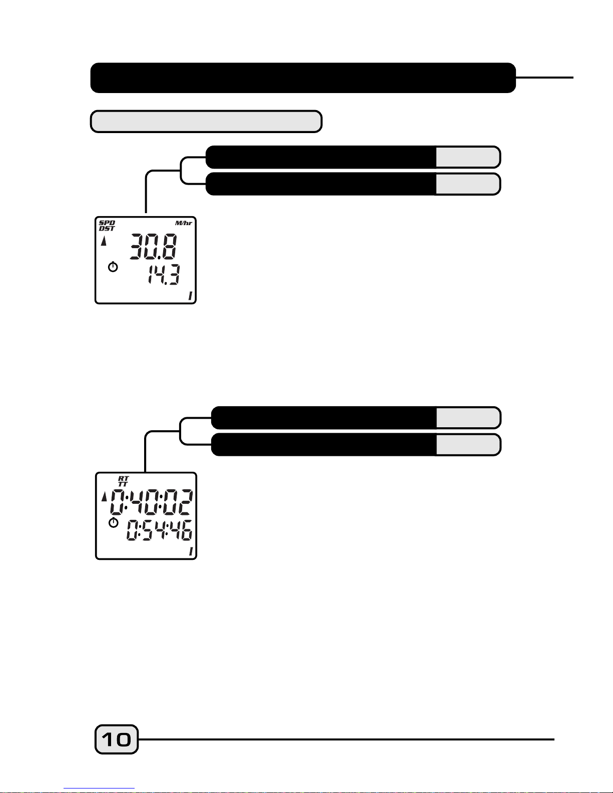
SPD displays the current Speed and is updated
continuously. DST displays the current Trip
Distance and automatically resets after the
maximum trip distance (999.9) is achieved.
Trip distance is displayed in the SPD/DST
screen mode and starts automatically when the
wheel rotates and TT Timer is active. Reset
DST to zero by pressing Button #3 for 2
seconds with the timers turned off in any
screen mode except STP/ID or STP/IA.
SPD
DST
V100A PRIMARY FUNCTIONS
UPPER SCREEN MODES
SPEED
TRIP DISTANCE
RIDE TIME
TOTAL TIME
Ride Time and Total Time functions are shown
simultaneously. Ride Time (RT) measures
actual riding time and starts automatically
when the timers are set to "0:00:00" and the
wheel rotates. Total Time (TT) shows the total
elapsed trip time from start to finish. Like RT, TT
starts automatically when the wheel rotates
ONLY when the timers are set to "0:00:00", or
it can be started manually by pressing Button
#3 in the RT/TT screen mode ONLY. TT can only
be stopped manually by momentarily pressing
Button #3 in the RT/TT screen mode at the end
of a ride. To reset both RT and TT to zero, turn
the timers off and press Button #3 for at least 2

AVG
MAX
seconds. Note: Whenever TT is activated, the stopwatch icon
appears; otherwise it does not appear. The TT Timer must be
active in order for the RT Timer to accumulate Ride Time and for
the computer to calculate current ride data.
CAUTION: If RT and TT timers are not 0:00:00 and you have
stopped them manually, then they MUST be restarted manually
by pressing Button #3 in the RT/TT mode. If not, the
computer will not record speed or other ride data. RT and
TT timers can be manually activated or deactivated only
from the RT/TT screen mode.
Riding Tip: If the bike is in motion and Button #3 is held down
in the RT/TT screen mode with the timers deactivated, the ride
timers reset to 0:00:00. When Button #3 is released, both RT and
TT will start with the next wheel input. This is a good way to
begin timing a race or training ride with a rolling start.
Average and Maximum Speed readings are
displayed simultaneously in the AVG/MAX
screen mode. Average Speed is updated every
0.1 miles or Km traveled. Reset both to zero
by pressing Button #3 for 2 seconds with
timers turned off in any screen mode except
STP/ID or STP/IA.
AVERAGE SPEED
MAXIMUM SPEED
SPD
CAD
ALT
%
LOWER SCREEN MODES
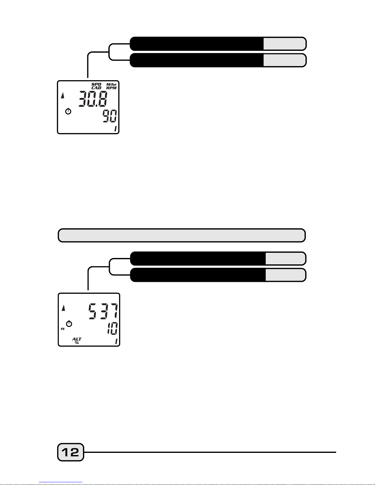
When installed, the Cadence kit measures and
displays pedal Cadence in Revolutions Per
Minute (RPM). The SPD/CAD screen function
letters appear ONLY when the Cadence
hardware is installed and a Cadence signal
received by the head unit. After a current ride
data reset, (Button #3 for 2 seconds with the
timers off) the function letters will disappear,
but they will come back on with the next
Cadence input. Note: RT and TT timers
MUST be activated in order for Speed and
Cadence to function.
*(optional)
SPEED*
CADENCE*
In the ALT/% screen mode, current Altitude is
displayed in feet (ft) or meters (m) on the
upper line. The lower line shows the current
Percent Grade (%) of the road or trail that you
are on: either uphill, as indicated by a whole
number, or downhill, indicated by a number
preceded by a minus sign (-). Note: A
secondary screen that displays your
Maximum % upgrade (climbing) and
Maximum % downgrade (descending) can be
displayed by pressing Button #1 for 2 seconds
in the ALT/% screen mode.
ALTITUDE
PERCENT GRADE
CLK
ODO
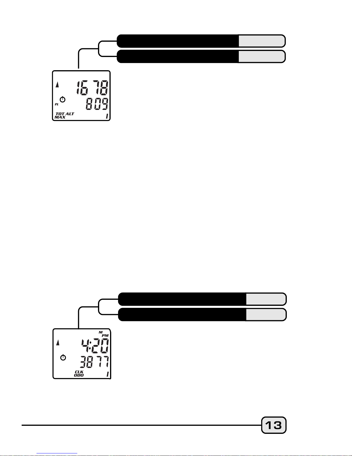
The time is displayed in the CLK/ODO screen
mode and features a user selectable 12 or 24
hour format. The Odometer displays cumu-lative
distance until an All Clear Total Reset is
performed, the battery is changed*, or the ride
distance exceeds the maximum limit, after which
the Odometer will automatically reset to zero.
*Note: Odometer reading can be reinstalled
by user after a battery change.
CLOCK
ODOMETER
TOT ALT
MAX ALT
Total Altitude displays the cumulative altitude
gain achieved for any given ride in feet or
meters on the upper line. The Maximum
Altitude or highest elevation attained during a
ride is displayed on the lower line. Note: TOT
ALT does not include descents. Both Total and
Maximum Altitude readings can be cleared by
pressing Button #3 for 2 seconds with the
timers turned off in any primary screen except
STP/ID or STP/IA.
CAUTION: Whenever you clear ride data
between rides or during a ride, you must
recalibrate your Altimeter before you start
riding again. Otherwise the Altimeter will not
function.
Riding Tip: Before you clear ride data (especially
during a ride), always check your "current"
altitude reading so you will know your present
elevation when you recalibrate your altimeter. To
recalibrate properly and most accurately, you
need to know either your exact current altitude
or the current barometric pressure at sea level
for your locale.
TOTAL ALTITUDE
MAXIMUM ALTITUDE
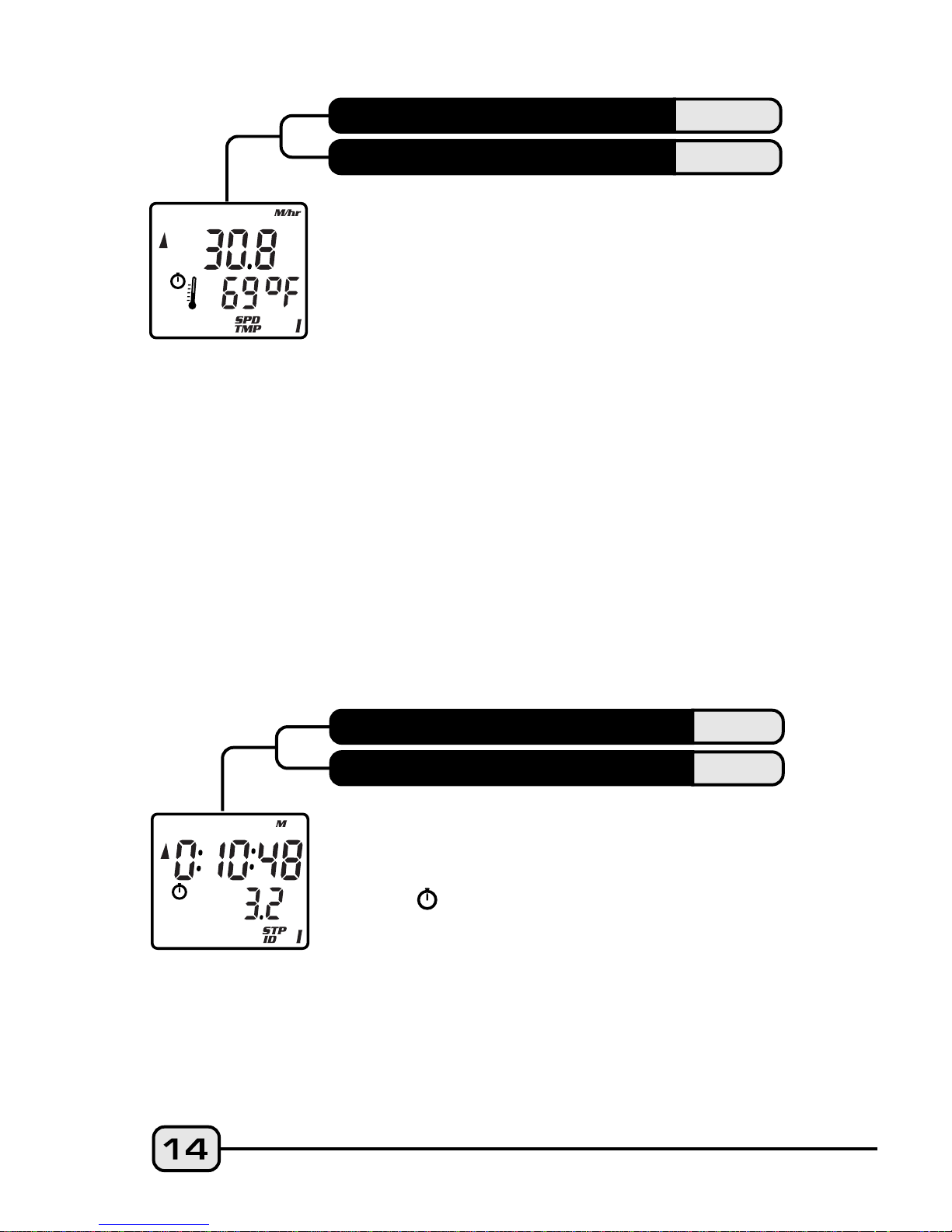
SPD
TMP
STP
ID
Current Temperature is displayed in the lower
screen digits and updated once per minute.
The thermometer icon illuminates when the
Temperature display is active, and the right
digit displays the scale selected in degrees
Celsius "C" or degrees Fahrenheit "F". Below
zero readings are indicated by a minus sign (-).
Note: A secondary screen displays Maximum
and Minimum Temperatures on the upper
and lower lines respectively. Press and hold
Button #1 for 2 seconds to access the
Max/Min TMP screen. Press Button #1 again to
return to the SPD/TMP primary screen.
Note: The temperature reading can
sometimes vary due to the computer head
unit being heated by direct sunlight; which can
heat the case hotter than the actual air
temperature.
SPEED
TEMPERATURE
The independent Stopwatch (STP) is operated
by Button #3 in the STP/ID screen mode. STP
operates in conjunction with the RT/TT
timers ( icon must be visible) and can be
started or stopped by pressing Button #3.
The Intermediate Distance function tracks
an intermediate distance within a longer ride.
ID does not affect overall Trip Distance or
current ride data, but it operates the same as
the DST function. From the STP/ID screen mode
with timers active, press Button #3 to start
STOPWATCH
INTERMEDIATE DISTANCE
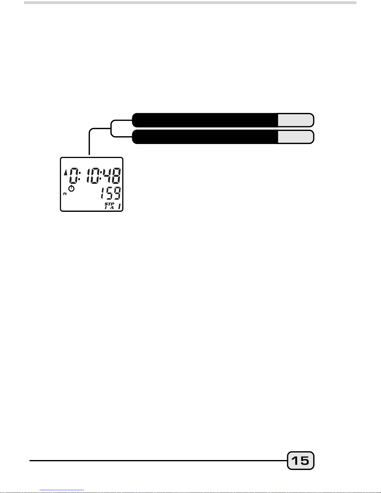
Stopwatch and ID functions; press Button #3
again to stop functions and freeze data for
review. Reset Stopwatch, Intermediate Distance
and Intermediate Altitude to zero by pressing
Button #3 for 2 seconds.
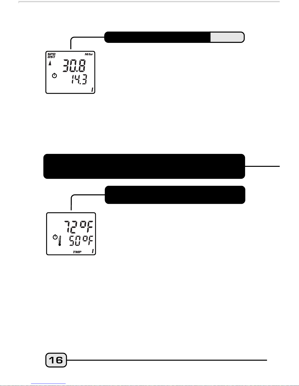
STP
IA
Like the Intermediate Distance function
described above, Intermediate Altitude tracks
an intermediate climb within a longer ride and
displays it on the lower line. Both functions are
activated when the Stopwatch function is
engaged. To switch from the STP/ID screen to
the STP/IA screen and back again, press Button
#1 for 2 seconds. Intermediate Altitude does
not affect Total Altitude data, but it operates the
same as the TOT ALT function. From the STP/IA
screen and with the RT/TT timers active, press
Button #3 to start the Stopwatch and the
Intermediate Altitude functions running;
press Button #3 again to stop the functions
and freeze the data for review. Reset Stopwatch
and both Intermediate Distance and Altitude
to zero by pressing Button #3 for 2
seconds.
STOPWATCH
INTERMEDIATE ALTITUDE
I
II
V100A SECONDARY FUNCTIONS
& FEATURES
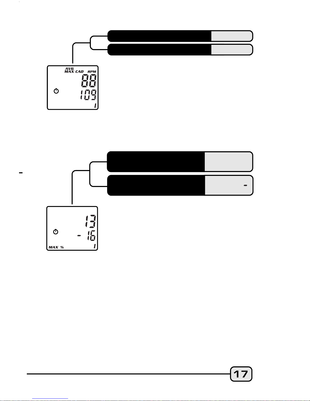
MAXIMUM & MINIMUM
TEMPERATURE
To display both the Maximum and Minimum
Temperature readings, press and hold Button #1
for 2 seconds in the Temperature SPD/TMP
screen mode. Note: The screen will flash to
indicate that the computer is displaying data
in a secondary screen. To return to the primary
SPD/TMP screen mode, press Button #1 again.
When ride data is reset by holding Button #3
with the timers stopped, both Maximum and
Minimum Temperatures reset to the current
Temperature.
DUAL BIKE MEMORY
The V100A can be calibrated for two bicycles. It
will store separate Wheel Size, Service Timer,
Odometer and Altitude settings, as well as
different formats selected for Time, Temperature,
Speed and Distance. The current bike number
(I or II) is always displayed in the lower right
corner of the screen. To switch the computer
quickly from Bike I to Bike II, go to the first
screen in the Normal Operating Mode Setup
program. (See SETUP section below for
details.)
When the Cadence mounting kit is installed, the
V100A displays both Average and Maximum
Cadence in a secondary screen. Press and
hold Button #1 in the SPD/CAD screen mode
for 2 seconds. The Average and Maximum
Cadence functions appear on the upper and
lower lines respectively. Press Button #1
once again in order to return to the primary
SPD/CAD screen. *(optional)
AVERAGE CADENCE*
AVG CAD
MAXIMUM CADENCE*
MAX CAD
These secondary functions can be reached by
holding Button #1 for 2 seconds in the ALT/%
screen mode. This screen shows the Maximum
Percent Grade attained on a current ride
while climbing (upper line) or descending
(lower line). The percent grade for descents is
preceded by a minus sign (--). Note: This
screen will flash to indicate that the computer
is displaying data in a secondary screen.
Press Button #1 again to exit to the ALT/%
primary screen.
MAXIMUM PERCENT
GRADE-CLIMBING
MAXIMUM PERCENT
GRADE-DESCENDING
MAX %
MAX % ( )
The Speed Comparator symbols on the left
side of the display screen indicate whether
current Speed is above or below current
Average Speed. A positive ( ) or negative
( ) symbol appears in the upper left part of
the screen in all primary screen modes. The
Speed Comparator symbols do not appear if
Speed (SPD) and Average Speed (AVG) are
the same.
SPEED COMPARATOR
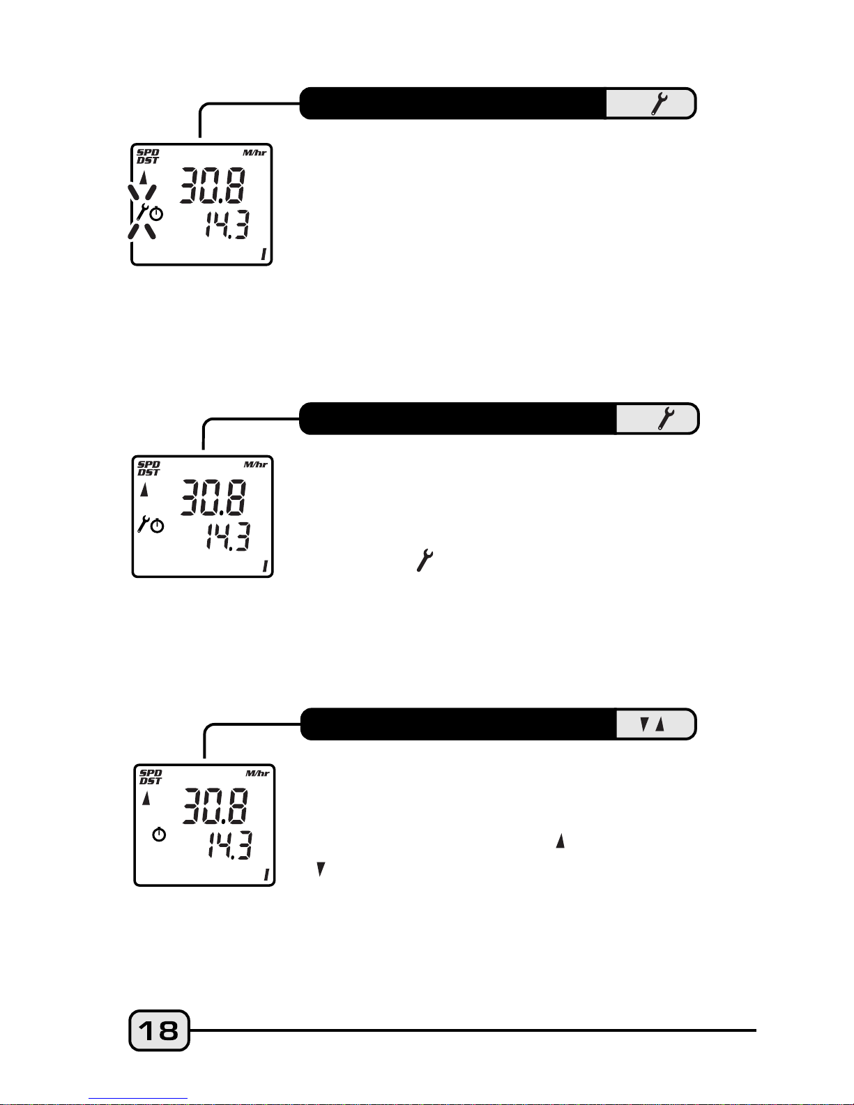
The V100A Service Timer icon has been
programmed to signal low battery power in
the head unit. When the battery runs low
and needs to be replaced, the Service
Timer icon ( ) will illuminate and stay "on"
(no blinking). Replace the head unit battery
as soon as possible. Rapid blinking of the
Service icon indicates both low battery
power and expiration of the preset service
time interval.
LOW BATTERY ALERT
Alerts rider when Ride Time reaches a preset
limit for a maintenance check on the bike or
any main component. Suspension forks, rear
shocks, chains, etc. require service at specific
time intervals set by manufacturers. Vetta's
Service Timer allows the rider to preset an
exact number of riding hours during Setup,
then signals (slow, flashing wrench icon) when
the service time limit has been reached. (See
SETUP section below for details.)
SERVICE TIMER
 Loading...