

Page 1
WARNINGS & CAUTIONS
Vetta cycle computers are sophisticated electronic instruments. Vetta recommends that this product
•
be installed only by a qualified bicycle retailer. Failure to read these instructions and/or improper
installation of this device may void the warranty. If in doubt about any aspect of the installation
or operation of this product, consult your local bicycle retailer for clarification.
The head unit is water resistant and sealed to withstand wet weather conditions. However, do not
•
deliberately place it in water.
Avoid leaving the head unit exposed to extremely hot weather conditions.
•
Vetta encourages you to ride safely. Wear a helmet every time you ride, use front and rear lights at
•
night, and always keep your eyes on the road ahead of you.
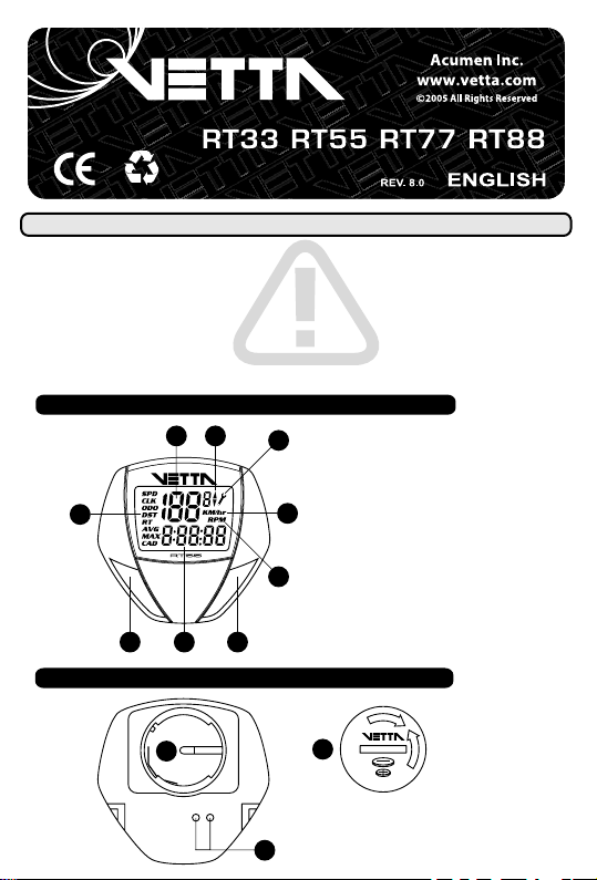
HEAD UNIT: FRONT
A
B
C
A
Upper Display (Speed)
B
Speed Comparator Icon
C
Service Timer Icon
D
Speed/Distance Units
E
RPM Indicator
G
D
F
Lower Display
G
Function Icons
E
Set/Select Button (Left)
1
Mode/Advance Button (Right)
2
1
F
HEAD UNIT: REAR
B
2
O
S
L
E
C
O
P
E
C
A
B
A
C
N
C
2
R
3
2
0
Contact Points
Battery Compartment
Battery Cover
Page 2
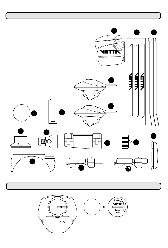
COMPONENT ILLUSTRATIONS
1
Head Unit Battery (CR2032 - 3V)
2
WL Wireless Speed Transmitter Battery (A23 - 12V)
3
Wired Cadence Sensor (RT77)
4
Cadence Magnet (RT77)
5
WL Wireless Speed Transmitter (RT88)
6
Spoke Magnet
7
Wire Securing Tape
8
Wired Speed Sensor
9
Mounting Bracket Pad
10
Riser Handle Bar Bracket (You may choose 9 or 10 according
to the style of your bicycle handlebar.)
11
Zip Ties
12
Wireless Mount (RT88)
13
Wired Mount
14
Spacer
15
Transmitter Mounting Pad
0
2
3
R
2
C
3
L
V
1
L
O
E
L
C
T
L
M
I
U
T
I
H
4
2
6
9
12
BATTERY INSTALLATION
3
V
5
11
7
3
3
8
15
10
0
2
3
R
2
C
L
L
O
E
L
C
T
L
M
I
U
T
I
H
14
O
S
L
E
C
O
P
E
N
C
2
R
3
2
0
Page 3
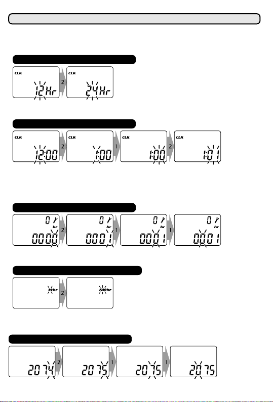
MAIN UNIT SETUP
All RT series computers are programmed to enter the Setup mode after battery installation. In Set-Up,
Button #1 is used to select or set a value and to advance to the next digit or screen mode. Button #2 is
used to switch between settings and to increase values.
SET 12/24 CLOCK
Press Button #2 to switch between flashing "12" and "24" hour formats. Press Button #1 to select desired
format and advance to time setting.
SET TIME
To set the time in CLK mode: Press button #2 to advance hour digits to correct hour (hold button for rapid
advance). Press Button #1 to select and advance to minutes setting. Press Button #2 to advance minute
digits and press Button #1 to select. (To change the CLK format, time or service time interval, press
and hold Buttons #1 and #2 simultaneously for 2 seconds in the SPD/CLK screen mode until "12/24"
hour format digits flash).
SET SERVICE TIMER
Press Button #2 to advance hour digits to desired total hours and press Button #1 to select and advance
(Maximum hour setting = 1999 hours).
SET SPEED/DISTANCE SCALE
Press Button #2 to switch between "M/hr" and "KM/hr" and Button #1 to select desired units and
advance. (To change units in SPD/ODO screen mode, press and hold Buttons #1 and #2
simultaneously for 2 seconds until "M/hr" begins to flash).
SET WHEEL SIZE
Default wheel circumference setting is 2074mm. Choose correct wheel circumference figure from Wheel
Reference Chart. Press Button #2 to advance digits as needed and Button #1 to select and advance.
(Range: 0050-2999mm).
Page 4
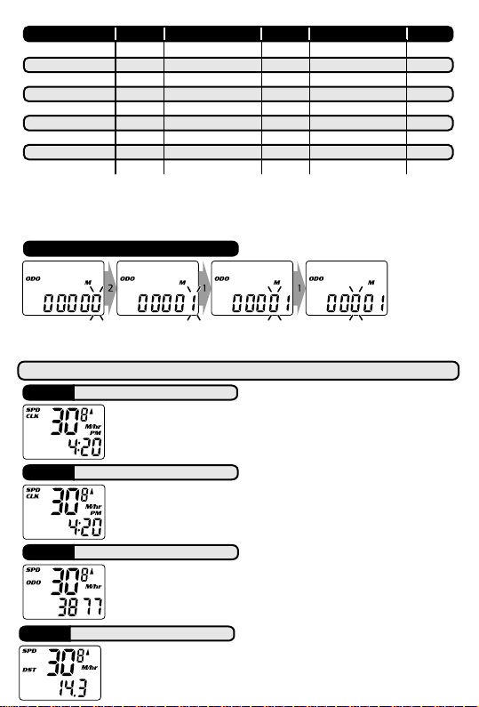
TIRE SIZE CIRC TIRE SIZE CIRC
If your wheel size is not on the chart, or if you want a more precise calibration, wheel circumference
may be calculated as follows:
Mark the tire and a spot on the floor. Roll the wheel forward one complete revolution until the tire mark
touches the floor again and mark that spot. Measure the distance between the marks on the floor in
millimeters and enter the result into the computer. (1 inch = 25.4mm)
2180700c x 38mm
2168700c x 35mm
2155700c x 32mm
2145700c x 30mm
2136700c x 28mm
2124700c x 25mm
2105700c x 23mm
2074700c x 20mm
2130700c Tubular
TIRE SIZE CIRC
1990650c x 23mm
1945650c x 20mm
216127" x 1-1/4"
215527" x 1-1/8"
213526" x 2.3"
20" x 1-1/4"
211526" x 2.25"
209526" x 2.1"
16" x 2.0"
207426" x 2.0"
16" x 1.95"
205526" x 1.9"/ 1.95"
16" x 1.5"
203526" x 1.75"
198526" x 1.5"
195326" x 1.25"
191326" x 1.0"
191624" x 1.9"/ 1.95"
1618
1253
1257
1206
SET ODOMETER
Press Button #2 to advance digits to previous mileage reading (after battery change). Press Button #1 to
select and advance to next digit. After final selection, computer will exit Setup and enter SPD/CLK screen
mode (Maximum setting: 99999).
PRIMARY FUNCTIONS
SPD RT 33|55|77|88
Speed is shown at all times on upper display. It is accurate to 0.1 M/hr or KM/hr and
the maximum reading is 139.9 M/hr or 199.9 KM/hr.
CLK RT 33|55|77|88
Time is displayed in user-selected 12 or 24 hour formats. (To change the CLK
format, time or service time interval, press and hold Buttons #1 and #2
simultaneously for 2 seconds in the SPD/CLK screen mode until "12/24" hour
format digits flash).
ODO RT 33|55|77|88
The odometer displays distance to 99999 Miles or Kilometers (1.0 mile/km). User
selectable ODO setting in Setup mode. Note: Odometer units (initialized during
Setup). (To change units in SPD/ODO screen mode, press and hold Buttons #1
and #2 simultaneously for 2 seconds until "M/hr" begins to flash).
DST RT 33|55|77|88
Displays trip distance of current ride to a maximum of 999.9 miles or kilometers (0.1
mile/km). To reset trip distance DST (+ MAX, AVG, RT, AVG/CAD, MAX/CAD) to
zero in normal operation, hold both buttons simultaneously for two seconds in
SPD/DST screen mode.
Page 5
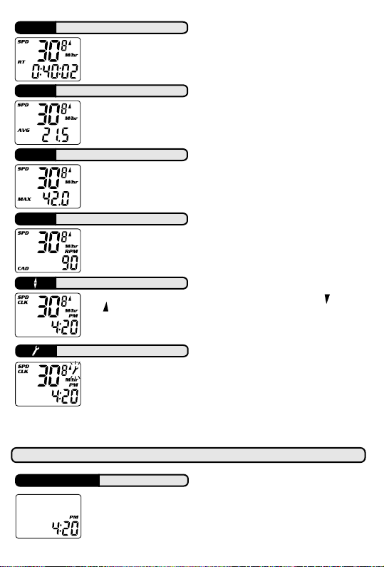
RT RT 55|77|88
Displays actual, cumulative ride time to 9:59:59. Reset to zero manually by
pressing and holding Buttons #1 and #2 simultaneously for two seconds in the
SPD/DST screen mode.
AVG RT 55|77|88
Average Speed is displayed in the SPD/AVG screen mode and reads to within 0.1
miles or kilometers per hour. Reset to zero manually by pressing and holding
Buttons #1 and #2 simultaneously for two seconds in the SPD/DST screen
mode.
MAX RT 55|77|88
Maximum Speed is displayed in the SPD/MAX screen mode and reads to within 0.1
miles or kilometers per hour. Reset to zero manually by pressing and holding
Buttons #1 and #2 simultaneously for two seconds in the SPD/DST screen
mode.
CAD RT 77
Cadence is displayed in the SPD/CAD screen mode and measures revolutions per
minute (RPM) of the crank. The RPM indicator lights when the CAD function is
displayed.
RT 55|77|88
Speed Comparator: Arrow symbols indicate if current speed is slower or faster
than current average speed.
RT 33|55|77|88
Service Timer: Blinking wrench icon alerts rider when scheduled maintenance is
required for suspension shocks, chains or other components. Elapsed riding time
and current Service Timer setting can be viewed on upper and lower displays in
Setup mode. To view or change Service Timer interval, CLK format and time
setting, press and hold Buttons #1 and #2 for 2 seconds in the SPD/CLK screen
mode until "12/24" hour format digits flash. To reset ride time to "0", press
Button #2 when elapsed time digits are flashing during Setup. To disable
Service Timer, enter "0" hours as Service Time Interval in Setup.
SPECIAL FEATURES
SLEEP MODE RT 33|55|77|88
To conserve battery life, computer enters Sleep Mode after 5 minutes without
input from buttons or speed sensor and displays the time. Computer exits Sleep
Mode and returns to screen last displayed with input from buttons (RT
33/55/77/88) or wheel (RT 33/55/77).
Page 6
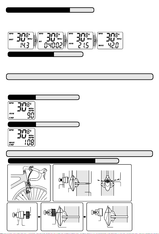
FREEZE FRAME MEMORY RT 55|77|88
Rider can freeze Distance, Ride Time, Average Speed and Maximum Speed readings at any time by
pressing Button #1 for two seconds while in the SPD/DST or SPD/RT screen modes. Display flashes to
indicate it has been frozen. Saved data can be scrolled and reviewed by pressing Button #2. Press Button
#1 to return to DST or RT screens.
ALL CLEAR RESET RT 33|55|77|88
All Clear Reset: Remove battery and reinstall. When you remove the battery all data and all time and
odometer settings will be cleared. When battery is reinstalled, computer will automatically enter the
Setup program.
RT 77 SECONDARY FUNCTIONS
Secondary screen functions include Average Cadence and Maximum Cadence. To access, press and hold
Button #1 while in the SPD/CAD screen mode. Press Button #2 to switch between AVG/CAD and
MAX/CAD readings. Press Button #1 to return the primary SPD/CAD screen mode.
AVG/CAD RT 77
Average Cadence is displayed in the AVG/CAD screen mode. It is calculated by
dividing total revolutions by total ride time. Reset to zero manually by pressing
and holding Buttons #1 and #2 simultaneously for two seconds in the SPD/DST
screen mode.
MAX/CAD RT 77
Maximum Cadence is displayed in the MAX/CAD screen mode. It is updated once per
second based on current RT and Cadence readings. Reset to zero manually by
pressing and holding Buttons #1 and #2 simultaneously for two seconds in the
SPD/DST screen mode.
INSTALLATION PROCEDURES
Zip Tie
RT 33|55|77
Magnet
Sweep Path
WIRED SPEED SENSOR & MAGNET
Fig. A
Spoke Magnet
Spoke
Spacer
Spoke
Magnet
Spacer
Tip
Spoke
Wired
Speed Sensor
Alignment
Mark
Fork Leg
Spoke
Magnet
Spoke Magnet
Wired
Speed Sensor
Page 7
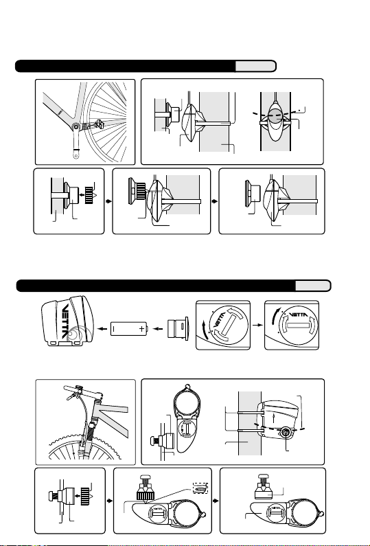
Attach the wired speed sensor with the zip-tie supplied and tighten the spoke magnet to the bicycle.
Adjust the sensor and magnet spacing with the spacer. Remove the spacer after snugging the zip-tie
down to hold the sensor in its final position. (See Figures above)
WIRED CADENCE SENSOR & MAGNET RT 77
Cadence
Magnet
Zip Tie
Magnet
Sweep
Path
Crank Arm
Cadence Sensor
Wired
Chain Stay
Cadence
Magnet
Spacer
Crank
Arm
RT77 only - Attach the wired cadence sensor and cadence magnet with the zip-ties supplied to the
bicycle. Adjust the sensor and magnet spacing with the spacer. Remove the spacer after snugging the
zip-tie down to hold the sensor in its final position. (See Figures above)
Cadence
Magnet
Spacer
Tip
Alignment
Mark
Cadence
Magnet
Wired Cadence
Sensor
WL WIRELESS SPEED TRANSMITTER & MAGNET RT 88
3
2
A
O
P
E
S
O
L
C
E
N
S
E
O
L
C
P
O
Zip Ties
Fork Leg
Speed Transmitter
O
P
E
N
v
2
1
3
2
A
WL Wireless
E
S
O
L
C
N
E
P
Magnet
Sweep Path
UP
Spoke
Magnet
E
S
O
L
C
O
E
S
P
E
O
L
N
C
N
E
P
O
A
3
2
E
S
O
L
C
O
A
2
3
2
1
Spoke
Magnet
O
P
E
N
v
A23
12V
WL Wireless speed transmitter uses an A23 12V battery. Install the battery as shown: remove cap,
install battery with positive (+) side up, replace battery cap.
Spoke
Magnet
E
P
N
O
C
E
L
S
O
E
N
E
S
O
L
C
Spoke
Spoke
5RCEGT
Spoke
Magnet
Spacer
Alignment
Mark
E
S
O
L
C
O
E
S
P
E
O
L
N
C
N
E
P
O
A
3
2
Tip
Page 8
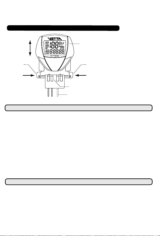
RT88 only - Attach the WL wireless speed transmitter with the zip-ties supplied and tighten the spoke
magnet to the bicycle. Adjust the transmitter and magnet spacing with the spacer. Remove the spacer
after snugging the zip-ties down to hold the transmitter in its final position. (See Figures above)
MOUNTING BRACKET & HEAD UNIT
OUT
Head Unit
IN
Locking
Tab
UNLOCK UNLOCK
Wired
Mount
Cadence RT 77
Locking
Attach mounting bracket.
Note: Be sure to leave
enough slack in the wire to
accommodate the movement
of fork and handlebars.
Tighten mounting bracket as
needed. (See fig. "A") Slide
Tab
main unit into bracket as
shown (left) until it clicks into
position. Remove by pressing
in the two locking tabs as
shown. Secure wire with tape
supplied and by winding it
around cables.
INSTALLATION TESTS
Once installation is complete, the computer should be tested to make sure it is working properly.
To test speed installation:
Advance the computer to the SPD screen mode using Button #2.
Step 1:
Pick up the front of the bicycle and spin the front wheel. The computer should display a
Step 2:
speed reading within 2-3 seconds.
If there is no speed reading, check the alignment and spacing between the magnet and
sensor/transmitter. Make sure that the head unit is completely locked into position and the
handlebar mount is not over tightened. If this check does not solve the problem, talk to your Vetta
Retailer or connect to www.vetta.com.
To test cadence installation:
Turn the crank backwards or ride the bike a short distance. After a few revolutions, a cadence reading
should appear on the lower line of the SPD/CAD display. If there is no cadence reading, check the
alignment and spacing between the magnet and sensor.
IMPORTANT: Following the installation tests above, make sure that the spoke magnet
locking screw and all zip ties are properly tightened. CAUTION: Do not over tighten!
PROBLEM/ITEMS TO CHECK/SOLUTION
Current speed reading is erratic or does not appear.
•
Check the alignment of the wheel magnet and sensor, and the distance between the two
components. Realign the magnet and sensor with the spacer.
Current speed reading is erratic or does not appear.
•
Inspect the wiring for any breaks or kinks. Replace mounting bracket and sensor as needed.
Incorrect data appears on screen during operation.
•
Accuracy of the Setup data may be a problem (wheel size setting, etc.).
Data display is extremely slow.
•
Computer LCD does not like extremely low temperatures. Operating range is: 0
º
F. Return the computer to a warmer climate.
122
º
C to 50ºC or 32ºF to
Page 9

Screen is dark and display characters look "strange".
•
Computer screens do not like to be left in direct sunlight for extended periods of time. Move the
computer into the shade until the screen recovers. No effect on data.
Screen reading is weak or fading.
•
Symptom of a weak battery. Replace the battery.
Screen readings are erratic and read too high or too low.
•
Symptom of a weak battery. Replace the battery.
Screen "frozen", no response to buttons.
•
Symptom of a weak battery. Replace the battery.
No display whatsoever.
•
Battery is completely dead, or not installed. Replace or install the battery.
WARRANTY RETURN & REPAIR POLICY
Acumen Inc, warrants all Vetta products, to the original purchaser, to be free of defects in materials or
workmanship for a period of three years from the original date of purchase. Acumen Inc will, at its sole
discretion, repair or replace any product deemed defective. This express warranty is in lieu of all other
warranties, either expressed or implied. Any warranties of merchantability or fitness for a particular
purpose are limited to the three years duration of the above express warranty. Acumen Inc will not be
held liable for any incidental or consequential damages.
If you ever experience a problem with the function of your Vetta RT cycle computer, please contact or
visit your local Authorized Acumen Inc Dealer for assistance.
Should you experience a problem with your Vetta RT cycle computer that cannot be solved by your
local Acumen Inc Dealer, please follow these simple steps to assure quick and efficient processing of
your claim.
Step 1:
Contact the appropriate Acumen Inc Customer Service Center listed below for help and to
obtain a Return Authorization Number (RA Number).
Step 2:
Send the unit back to the appropriate Acumen Inc Customer Service Center, together with
the original copy of your purchase receipt and a detailed explanation of the problem that
you are experiencing. Please be sure to write the Return Authorization Number (RA
Number) on your return package.
ACUMEN INC CUSTOMER SERVICE CENTERS
Acumen Inc.
101A Executive Dr., Suite 100,
Sterling, VA 20166, USA.
Acumen Europe BV
Splijtbakweg 117, 1333 HJ, Almere,
The Netherlands.
Email: [email protected]
Website: www.vetta.com
 Loading...