

Page 1
Vetta’s RT200 series are the upgraded version of all RT series cycle computers. It is recommended that these
products are to be installed by a qualified bicycle retailer. Failure to read the instructions and/ or improper installation
of the device may void the warranty. If you have any doubts about the installation or the operations, contact your local
bicycle retailer for clarification.
WARNINGS & CAUTIONS
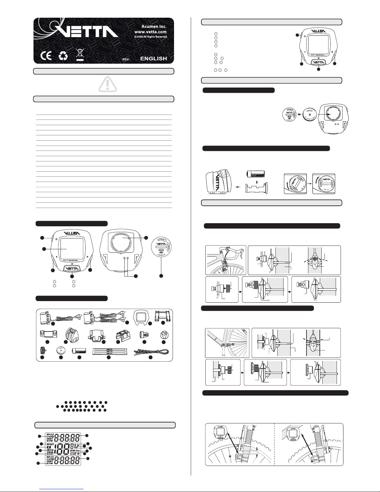
HEAD UNIT
COMPONENTS
RT255 RT255L
RT277 RT288 RT288L
1. Button
2. Button
3. Button
4. Button (RT255L/288L)
5. Main Display
6. Contact Pins (RT255/255L/277)
7. Battery Compartment
8. Battery Cap
Heavy Duty Metal Braided Cable
Wireless Transmission
Replaceable Front Cover
Screen Display Window
NiteLite w/ SmartLite
EZ Tire Set
Service Timer
Speed Comparator
Auto Awake & Start-up
Energy Efficient programmable Auto Start
Current Speed
Average/Maximum Speed
Ride Time
Cumulative Odometer
Trip Distance
Multi Freeze Frame Memory
Lap
Current/Average/Maximum Cadence
12/24 Hour Clock
FUNCTIONS / FEATURES
RT255/255L includes:
1 3 4 5 9 11 12 14 15
RT277 includes:
2 3 4 5 9 10 11 12 14 15
RT288/288L includes:
3 4 5 6 7 8 9 11 12 13
1. Wired Spd Sensor with Mounting Bracket
(with Heavy Duty Harness)
2. Wired Spd & Cad Sensor with Mounting Bracket
(with Heavy Duty Harness, for Rear Wheel Pick-up)
3. Extra Clear Front Cover
4. Bracket Rubber Pad
5. Bracket Rubber Pad (Riser Handlebar)
6. WL Wireless Speed Transmitter
7. Wireless Mounting Bracket
8. Wireless Transmitter Shim
9. Bladed Spoke Magnet
10. Composite Cadence Magnet
11. Spacer
12. Head Unit Battery (CR2032, 3-Volt)
13. Wireless Transmitter Battery (A23, 12-Volt)
14. Wire Securing Tape
15. Zip-Ties
1
2
3
4
RT255 RT255L RT277 RT288 RT288L
• •
••
••
•
•
•
•
••
••
• ••
••
• ••
••
••
• ••
••
• ••
••
• ••
••
• ••
••
• ••
••
• •
•
•
••
• ••
• ••
11 16 11 11 16
10 15 10 10 15
3 3 3 3 3
1.0
4
5
1
3
2
6
7
8
1
7 8 9
10
11 12 13 1514
2
4
3
5 6
LCD DISPLAY
1. Upper Display
2. Middle Display (Speed)
3. Lower Display
4. Service Timer/ Low Battery Icon
5. Speed Comparator Icon
6. Speed / Distance Units
7. Setup Mode Icon
8. Function Icons
9. RPM / RT/ PM/ TM Icon
10. Speed & Split Time Icon
11. Freeze Frame Memory Icon
12. Lap Icon
13. Auto Start Icon
1
2
5
6
7
8
9
10
11
13
12
4
3
Important:
Do not use Zip-Ties, use the tapes provided with the package to hold wires to the frame, fork, bars or stem
to avoid damaging or cutting the wires accidentally. Make sure excess wire is taped down or wrapped around brake cable
housing to secure it.
BATTERY INSTALLATION
INSTALLATION
WIRED CADENCE SENSOR & MAGNET (
RT277)
Attach the Wired Cadence Sensor & Composite Cadence Magnet with the Zip-Ties supplied to the bicycle. Adjust the
sensor & magnet spacing with the spacer. Remove the Spacer after snugging the Zip-Ties down to hold the sensor in its
final position.
4
1
3
2
BUTTON FUNCTIONS
WIRED SPEED SENSOR & MAGNET (
RT255/255L)
Press momentarily
Button : Upper Screen Modes
Button : Lower Screen Modes
Button : F-Button or Lap Button
Button : NiteLite (RT255L/288L)
Press & hold for 2 seconds
Button : Recall Freeze Frame Memories or Lap Data
Button & when the lowest screen is in the CLK Mode: NOM Setup
Button & when the lowest screen is in the DST Mode: Reset ride data
to zero including the Frozen screens or Lap data
Button , & : All Clear Total Reset
Wired Cadence Sensor
Crank
Arm
Chain Stay
Spacer
Spacer
Tip
Alignment Mark
Crank Arm
Composite Cadence
Magnet
Wired Cadence Sensor
Zip-Tie
Composite
Cadence Magnet
Composite
Cadence Magnet
Composite
Cadence Magnet
Wired Speed Sensor
Wired Speed Sensor
Fork Leg
Bladed
Spoke Magnet
Bladed
Spoke Magnet
Bladed
Spoke Magnet
Bladed Spoke Magnet
Spoke
Magnet
Sweep Path
Zip-Tie
Spacer
Spoke
Spacer
Tip
Alignment Mark
Fig. A
1
2
3
4
3
1
1
1 223
2
Magnet Sweep Path
The RT200 series Head Unit use CR2032, 3-Volt Lithium button Cell batteries.
Battery Run Time (1 hour training / day): Approx.12 months (RT255/255L/277); Approx. 8 months (RT288/288L)
Important:
Most cycle computer problems are caused by weak or
dead batteries. See the Trouble Shooting section near the end of
the manual for details.
1. Remove the battery cap from the bottom of the Head Unit using
a coin.
2. Install a new battery as shown with the positive (+) side facing out. Do not touch or bend
any of the battery contacts during installation.
3. Screw the battery cap firmly into place and make sure that the O-ring seal does not get pinched or distorted.
Caution:
To avoid damage to the battery cap, do not over tighten.
HEAD UNIT
The WL Wireless Speed Transmitter uses an A23, 12-Volt battery. Remove the battery compartment using a coin and
install the battery in it with positive (+) side in, then replace the battery compartment.
Battery Run Time (1 hour training / day): Approx.10 months
WL WIRELESS SPEED TRANSMITTER (
RT288/288L)
A23, 12V
Attach the Wired Speed Sensor with the Zip-Tie supplied and tighten the Bladed Spoke Magnet to the bicycle. Mounting
the sensor as high up as on the fork leg. (Fig. A) Adjust the sensor and magnet spacing with the Spacer. Remove the
Spacer after snugging the Zip-Tie down to hold the sensor in its final position.
WL WIRELESS SPEED TRANSMITTER & MAGNET (
RT288/288L)
Tie the WL Wireless Speed Transmitter with Bracket Rubber Pad loosely by the Zip-Ties supplied to either in the front of
the left fork leg (see Fig.1 A) or at the back of the right fork leg (see Fig.1 B). For best signal reception, make sure the
distance between the Transmitter and the Head Unit is within 70 cm. At the same time, the Transmitter should be
2 ~ 4 cm (or more) away from the brake, to avoid blocking transmission signals by the brake. Adjust the transmitter
and magnet spacing with the Spacer. Slide and rotate the transmitter until the alignment mark just touches the spacer tip
on the magnet. Remove the Spacer after snugging the Zip-Tie down to hold the transmitter in its final position.
Within 70 cmWithin 70 cmWithin 70 cm
2~4 cm2~4 cm
2~4 cm
Fig.1 B
Fig.1 A
1
Page 2
WW
Fork Leg
Zip-Ties
A
2
3
C
L
O
S
E
O
P
E
N
Magnet
Sweep Path
Spoke
Bladed
Spoke
Magnet
Bladed Spoke
Magnet
A
2
3
C
L
O
S
E
O
P
E
N
Wireless Speed
Transmitter
A
2
3
C
L
O
S
E
O
P
E
N
Spacer Tip
Alignment
Mark
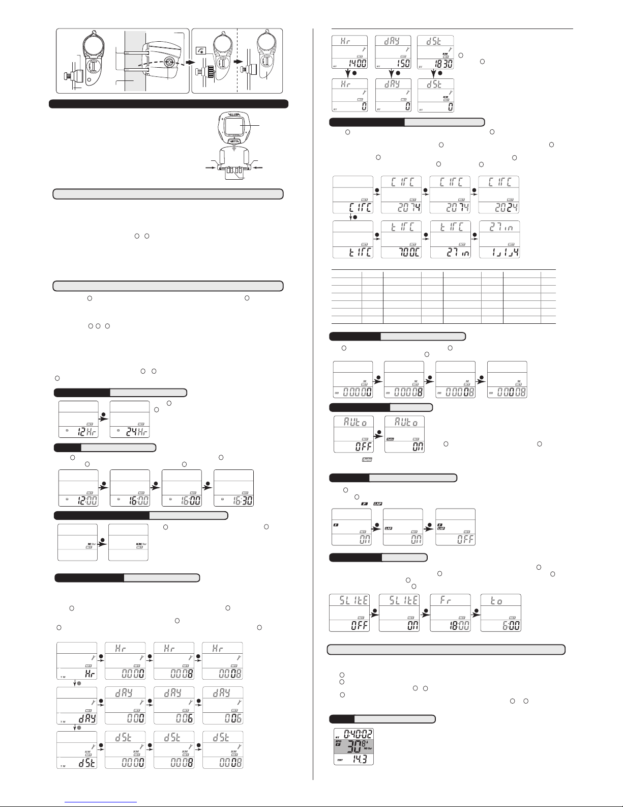
MOUNTING BRACKET & HEAD UNIT (
RT255/255L/277/288/288L)
Attach Mounting Bracket & Bracket Rubber Pad to the handlebar on the
“Sensor/Transmitter side” using the Zip-Ties provide. Adjust its position
to your liking and tighten the Zip-Ties.
Note: Be sure to leave enough
slack in the wire t o accommodate the movemen t of fork and
handlebars. (See Fig. A)
Slide the Head Unit into the Mounting Bracket as shown until it clicks
into position. Remove by pressing in the two locking tabs as shown.
Secure wire with tape supplied and by winding it around cables.
Locking Tab Locking Tab
UNLOCK UNLOCK
Wired Mounting Bracket
Head Unit
SETUP & PROGRAMMING
SERVICE TIMER RT 255|255L|277|288|288L
SPEED/ DISTANCE UNIT RT 255|255L|277|288|288L
INSTALLATION TESTS
Once installation is complete, the computer should be tested to make sure it is working properly.
To test the Speed Sensor/Transmitter installation:
Pick up the front of the bicycle and spin the front wheel. The LCD should display a speed- reading within 2-3 seconds.
To test the Cadence Sensor installation (RT277):
Advance the LCD to the CAD Mode using or . Turn the crank backwards or ride the bicycle a short distance. After a
few revolutions, a cadence reading should display on the LCD.
If there is no spe ed-reading or cadence read ing, check the alignment and spacing between the magnet an d
sensor/transmitter. Make sure that the Head Unit is completely locked into position. If these checks do not solve the
problem, talk to an Authorized Vetta’s Retailer or connect to www.vetta.com
.
Important:
Make sure the magnets locking screw and all Zip-Ties are properly tightened.
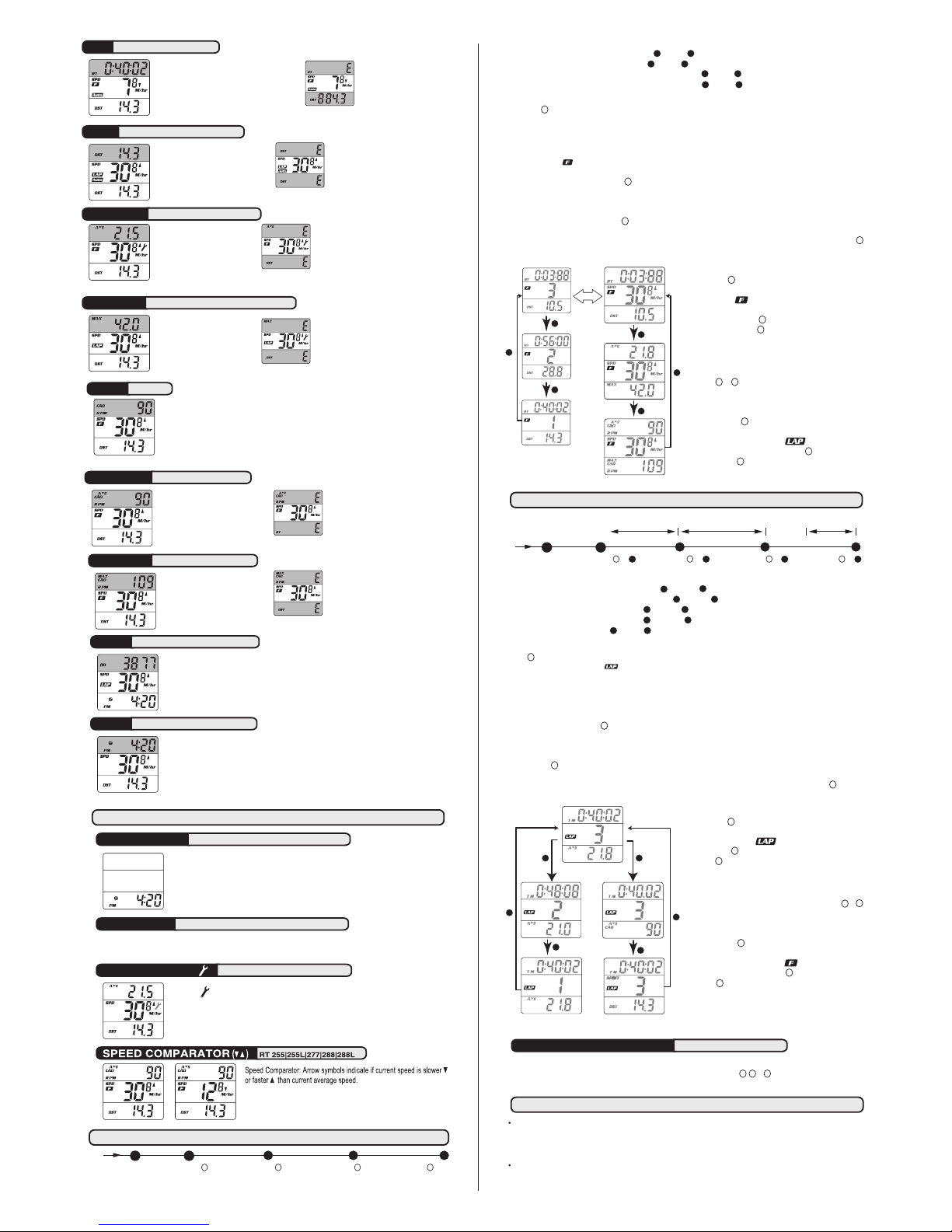
Service Timer could be programmed with a selected number of ride time (hours or days) or distance as the interval for
servicing the bicycle or any component on it, such as a front or rear shock.
The default settings “0000” means the Service Timer is turned off.
Press to scroll flashing hr (hour), day or dst (distance) as the Service Timer unit. Press to select the desired Service
Timer unit.
When the desired Service Timer unit has been chosen, press to scroll the flashing digit to the desired number. Press
1
to select this number and advance to next digit. Repeat this procedure until all digits are selected. Press to advance
the next Setup Mode. ( Maximum settings: hour / day / distance = 1999 / 999 / 9999 )
2
1 2
2
1
2
1
In Setup, Button is used to select or set a value and to advance to the next digit or Mode. Button is used to switch
between settings and to increase values.
Initial Setup
All RT200 series computers are programmed to enter the Initial Setup Mode after new battery replacement or all clear
total reset (press , & simultaneously for 3 seconds in any Mode).
In the Initial Setup, riders can program the Basic Settings for the computer, the content of settings are same as NOM
Setup for Basic Setting.
Important:
The computer CANNOT exit the Initial Setup Mode until all the Basic Settings are finished.
NOM Setup
After completed the Initial Setup, riders can change any values or correct any errors by re-entering the NOM Setup.
To enter the NOM Setup Mode press & hold & simultaneously when the lowest screen is in the CLK Mode. Press
3
any time to exit and advance to the previous Mode.
1
1 223
1 2
2 2 2
1
When the Ride Tim e (the elapsed time for Serv ice
Timer) or the elapsed distance begins to flash, press
2
to reset to zero;
OR press to reserve the digits, and advance to the
next Setup Mode.
Important:
In the Initi al Setup, the elapsed time [distance ] for
Service Timer doesn’t exist.
OR OR
1
1 2
1
2 1
2
1 2 1
2
2
1
Press to toggle between flashing M/hr and KM/hr. Press to select
and advance to the next Setup Mode.
Note: Speed/Distance Unit cannot be changed if there have been ride
data on screens. If you want to change the Unit, please make sure you
had cleared all ride data before entering the NOM Setup Mode. This
restriction does not apply to the Initial Setup after the 1
st
time battery
installation, new battery replacement or All Clear Total Reset.
12/24 CLOCK RT 255|255L|277|288|288L
TIME RT 255|255L|277|288|288L
2
Press to toggle between flashing 12 and 24 hour formats. Press
1
to select your desired format (without PM icon implies AM in 12
hour format) and advance to Time setting.
Press to advance hour digits to correct hour (hold button for rapid advance). Press to select and advance to minute
setting. Press to advance minute digits to correct minute. Press to select and advance to the next Setup Mode.
2 1 2
2
2
1
2
1
WHEEL/ TIRE SIZE RT 255|255L|277|288|288L
Press to toggle between flashing circ (circumference) and tire (tire type). Press to select the desired and advance
the settings.
If pre-set to circ (see Table of Tire Size Vs Circ), press to scroll the flashing digit to the desired number. Press to
select this number and advance to next digit. Repeat this procedure until all four digits are selected.
If pre-set to tire, press to scroll the flashing 700c, 650c, 27in, 26in, 24in, 20in or 16in. Press to select and advance
to next setting to complete the Tire Size. Again, press to scroll and press to finalize the Tire Size and advance to
the next Setup Mode.
ODOMETER RT 255|255L|277|288|288L
Press to scroll the flashing digit to the desired number. Press to select this number and advance to next digit. Repeat
this procedure until all five digits are selected. Press to advance the next Setup Mode. (Maximum setting: 99999)
TIRE SIZE CIRC
700c x 20mm 2074
700c Tubular 2130
650c x 23mm 1990
650c x 20mm 1945
27” x 1.25” 2161
27” x 1.125” 2155
26” x 2.3” 2135
TIRE SIZE CIRC
700c x 38mm 2180
700c x 35mm 2168
700c x 32mm 2155
700c x 30mm 2145
700c x 28mm 2136
700c x 25mm 2124
700c x 23mm 2105
TIRE SIZE CIRC
26” x 1.0” 1913
24” x 1.9/1.95” 1916
20” x 1.25” 1618
16” x 2.0” 1253
16” x 1.95” 1257
16” x 1.5” 1206
TIRE SIZE CIRC
26” x 2.25” 2115
26” x 2.1” 2095
26” x 2.0” 2074
26” x 1.9/1.95” 2055
26” x 1.75” 2035
26” x 1.5” 1985
26” x 1.25” 1953
2 1 1
FUNCTIONS
AUTO START RT288|288L
When Auto Start is On: The computer exit the Sleep Mode as soon
as it receives the speed signal or any button is pressed.
When Auto Start is Off: To conserve battery run time, the computer
will only exit the Sleep Mode when any button is pressed.
Press to toggle between flashing OFF or ON. Press to select
and advance to next Setup Mode.
2
F or LAP
RT 255|255L|277|288|288L
SMARTLITE RT 255L|288L
SPD
RT 255|255L|277|288|288L
SmartLite will turn on the night light for 3 seconds between pre-set intervals when any button is pressed. Press to toggle
between OFF and ON. When SmartLite is set to OFF, press to exit the Setup Mode. When SmartLite is set to ON, press to
select and advance the hour setting. Press to advance the hour digits to desired hour [range of Fr (from): 1:00 PM to 11:00 PM;
range of To (to): 1:00 AM to 11:00 AM]. Press to select and exit the Setup mode.
Speed is shown at all times on middle display. It is accurate to 0.1 M/hr or KM/hr and the
maximum reading is 139.9 M/hr or 199.9 KM/hr.
2 2
2
2
2
1
1
1
1
2
2
1
1
2 1
Press to scroll the flashing F (Freeze Frame Memory), LAP (Lap Data) and OFF (both of Freeze Frame Memory and
Lap). Press to select and advance to next Setup Mode.
Note: The icon or in the Normal Display Modes indicates F or Lap has been chosen.
2
1
2
1
1
2
1
2 1 1
1
1 2 1
21
2
The types and number of Modes of the upper screen are same as the lower screen. Depending on users’ habits, they can
decide where to put the desired Modes either on the upper or lower screen.
Press to change the Upper Screen Modes.
Press to change the Lower Screen Modes.
To enter the NOM Setup Mode, press & hold & simultaneously for 2 seconds when the lowest screen is in the CLK Mode,
Press at anytime to exit.
To reset all ride data (DST, AVG SPD, MAX SPD, RT, AVG/CAD*, MAX/CAD*) to zero, press & hold and simultaneously for 2
seconds when the lowest screen is in the DST Mode. (* RT277 Only)
1 2
2
1
1
2
3
Note: The icon Auto in the Normal Display Modes indicates the programmable Auto Start has been chosen.
2
Page 3
3
RT
RT 255|255L|277|288|288L
RT displays actua l, cumulative ride time to 1 00
hour. [If the time is less than 9:59:59 hours, the
display format will be h:mm:ss, eg. 0:09:59 means 9
minutes and 59 seconds. If the time is longer than
10 hours, the format will be hh:mm without seconds,
eg 11:28 means 11 hours and 28 minutes]
DST
RT 255|255L|277|288|288L
DST dis plays tri p di stanc e of
curre nt rid e to a ma ximum of 99 9.9
miles or ki lometers . It is accura te to
0.1 M ile or K M.
Not e: W hen the Trip Dis tance
excee ds 999. 9 mile s [kilo meters],
symbol “E” appears indicating that
further measurement is impossible.
Note: When the Ride Time e xceeds 99
hours and 59 minutes, or the Trip Distance
exceeds 999. 9 mile s [kilo meters], symbol
“E” appears indica ting that further
measurement is impossible.
AVG SPD RT 255|255L|277|288|288L
Average Spee d is accurate to
0.1 M/hr or KM/hr.
CAD RT277
Cadence measures revolutions per minute (RPM) of the crank.
MAX SPD RT 255|255L|277|288|288L
Note: When t he Ride Time
exceeds 99 hour s and 59
minutes, symbol “E” appears
indicat ing that further
measurement is impossible.
Note: When the Ride Time e xceeds 99
hours and 59 minutes, or the Trip Distance
exceeds 999. 9 mile s [kilo meters], symbol
“E” appears indica ting that further
measurement is impossible.
Maximum Speed is accurate
to 0.1 M/hr or KM/hr.
Note: When the Ride Time exceeds
99 hours and 59 minutes or the Trip
Distance ex ceeds 9 99.9 miles
[kil ometers ], symbol “E” appears
indicating that further measurement
is impossible.
AVG CAD RT277
Average Cadence is calculated
by dividing total revolutions of
the crank by the total ride time.
SLEEP MODE RT 255|255L|277|288|288L
Computer enters Sleep Mode after 5 minutes without input from any buttons or wheel, and
displays the clock only. Computer exits Sleep Mode and returns to the screen last displayed
when any button is pressed or the wheel turns. (if the Auto Start is pre-set to OFF, RT288/288L
can only exit the Sleep Mode when any button is pressed)
SMARTLTE RT 255L|288L
SmartLite will activate the NiteLite for 3 seconds between the user-defined period when any button is pressed. (see
Section of SmartLite Setup)
SERVICE TIMER( ) RT 255|255L|277|288|288L
Blinking “ ” alerts riders when the Service Time is reached.
OTHER FEATURES
ODO RT 255|255L|277|288|288L
The odometer displays distance to 99999 Miles or Kilometers. It is accurate to 1.0 Mile or KM.
CLK RT 255|255L|277|288|288L
Clock is displayed in user-selected 12 or 24 hour formats.
MAX CAD RT277
Max imum Ca dence is update d
once per second based on c urrent
Caden ce readi ngs.
Note: When the Ride Time exceeds
99 hours and 59 minutes or the Trip
Distance ex ceeds 9 99.9 miles
[kil ometers ], symbol “E” appears
indicating that further measurement
is impossible.
FREEZE FRAME MEMORIES (RT255/255L/277/288/288L)
3
...
0 1 2
15
16
RT=0:00:00
DST=0.0 Km
Press Button and
Store the Ride Data as F1
3
Press Button for F23Press Button for F153Press Button for F16
3
3
3
3
Recording Ride Data
Press (if it has been pre-programmed to Freeze Frame Memories) at any time in any Normal Modes to record.
When recording the Frames, the icon F will flash and the F# will display on middle screen.
After the recording, screens of RT/DST, AVG SPD / MAX SPD, AVG CAD / MAX CAD* will turn on in sequence, then flip
back to the previous Normal Display Mode.
Note:
1. The icon indicates the Multi Freeze Frame Memories has been chosen.
2. Freeze Frames can only be recorded when the wheels turn.
3. It will not record new memory if is pressed consecutively within 5 seconds.
4. New set of Freeze Frame cannot be recorded when in the Recall Mode.
5. Up to 11 (or 16 for RT255L/288L) sets of Freeze Frame (RT/DST, AVG SPD/MAX SPD, AVG CAD/MAX CAD*) can
be stored. The computer will stop record new memory if it is more than 11/16 and the middle screen will show “
F
” with
any further press of the button .
6.
If t he Ride Time is longer than 9 9 hours and 59 minute s or th e Dista nce is longer than 999 .9 KM or Miles , the
compu ter will stop re cording new memo ry. The mid dle scre en will show “
E
” wit h any fu rther pr ess of b utton .
(* RT 277 Only)
Reading Freeze Frame Memories
Press & hold for 2 seconds in the any Mode to read the
frozen ride data. The recall screens display the most recent
set first. Flashing indicates it is in the F recall screens. The
middle digits flips between the F# & the recorded speed for
every 2 seconds. Press momentarily to scroll the F ride
data screens and press momentarily to scroll the F#.
Note:
1. If there is no frozen screen recorded, the middle digits will
show “
--
”.
2.
To reset the Freeze Frame Memoir es to zero, pr ess &
hold
& simultaneously when the lowest screen is in
the DST Mode.
3. If no button is pressed for 1 minute the recall screen will
return to the previous Normal Mode automatically.
4. Press & hold for 2 seconds to switch the
F ride data
screen to Lap screens (if there are 2 or more than 2 sets
of frozen ride data). Flashing indicates it is in the
LAP recall screens. Press & hold again to change
back. Press to exit.
LAP FUNCTION (RT255/255L/277/288/288L)
RT/DST
AVG/MAX SPD
AVG CAD/MAX CAD (RT277 only)
flip
1
1
2
2
2
1
2
2
2
1
LAP TIME /AVG SPD
LAP TIME /AVG CAD
(RT277 only)
SPLIT TIME / LAP DST
3
2
1
1
2
2
3
2
Reading Lap Data
Press & hold for 2 seconds in the any Mode to read the
frozen ride data. The Lap recall screens display the most
recent set first. Flashing indicates it is in the Lap recall
screens. Press momentarily to scroll the Lap data screens
and press momentarily to scroll the Lap #.
Note
:
1. If there is no lap data recorded, the middle digits will show
“--”.
2.
To reset the Lap data to zero, press & hold &
simultaneously when the lowest screen is in the DST Mode.
3. If no button is pressed for 1 minute the recall screen will
return to the previous Normal Mode automatically.
4. Press & hold for 2 seconds to switch the Lap screens
to F ride data screens (if there are 2 or more than 2 sets
of frozen ride data.) Flashing indicates it is in the F
recall screens. Press & hold again to change back.
Press to exit.
3
2
1
1
2
2
2
3
1
1
Recording Lap Data
Press (if it has been pre-programmed to Lap function) at any time in any Normal Modes to record.
When recording the laps, the icon will flash and Lap # will display on middle screen (the starting point of Lap 1 will be “Str”).
After storing the data, screens of LAP TIME/AVG SPD, LAP TIME / AVG CAD*, SPLIT TIME / LAP DST will turn on in sequence,
then flip back to the previous Normal Display Mode.
Note:
1. The icon LAP indicates the Lap function has been chosen.
2. Laps can only be recorded when the wheels turn.
3. It will not record a new lap if is pressed consecutively within 5 seconds.
4. New Lap cannot be recorded when in the Recall Mode.
5. Up to 10 (or 15 for RT255L/288L) sets of Lap data (LAP TIME, AVG SPD, AVG CAD*, SPLIT TIME & LAP DST) can be
stored. The computer will stop record new lap if it is more than 10. The middle screen will show “
F
” with any further press of
the button .
6. If the Lap Time or Split Time is longer than 99 hours and 59 minutes or the Lap Distance is longer than 999.9 KM or Miles,
the computer will stop recording new lap. The middle screen will show “
E
” with any further press of the button .
(* RT277 Only)
3
3
3
3
3
...
0
0 3
2
1 2 3
15
2 3
3
2 3
2 3
1 2
3
15
RT=0:00:00
DST=0.0 Km
Press Button at 3Press Button at3Press Button at3Press Button at
Example
Lap Time of Lap 2: total ride time between point and point
Lap Distance of Lap 2: total distance between point and point
AVG Speed: average speed between point and point
AVG Cad: average cadence between point and point
Split Time: total time from point to point
Start
Lap 1 Lap 2 Lap 15
0 2
0 2
0 2
0 2
Example
Ride Time of F2: total ride time from point to point
Distance of F2: total distance from point to point
AVG/MAX Speed: average or maximum speed from point to point
AVG/MAX Cad: average or maximum cadence from point to point
TROUBLE SHOOTING
Current speed-reading is erratic or does not appear.
Check the alignment of the bladed spoke magnet and sensor/transmitter, and the distance between the two components.
Realign the magnet and sensor/transmitter with the spacer.
OR Inspect the wiring for any breaks or kinks. Replace Mounting Bracket and sensor as needed. (RT 255/255L/277)
Incorrect data appears on screen during operation.
Accuracy of the Setup data may be a problem (wheel size setting, etc.).
Review data in System Check mode and revise as needed.
All data entered in Setup Modes, as well as ride data (including the Multi Freeze Frame Memories and Laps), can be
cleared by performing an All Clear Total Reset. To clear the computer, press , & simultaneously for 3 seconds in
any Mode. The master screen will appear and show all segments, then automatically enter the Initial Setup Mode.
ALL CLEAR TOTAL RESET RT 255|255L|277|288|288L
1 2 3
Page 4

4
ACUMEN INC CUSTOMER SERVICE CENTERS
Acumen Inc.
101A Executive Dr., Suite 100, Sterling, VA 20166, USA.
Acumen Europe BV
Splijtbakweg 117, 1333 HJ, Almere, The Netherlands.
Email: [email protected]
Website: www.vetta.com
WARRANTY POLICY
ACUMEN INC. WARRANTS ALL VETTA (The Company) PRODUCTS AGAINST MANUFACTURER DEFECTS FOR A
PERIOD OF 3 YEARS. Su bject to the foll owing limitations , terms and cond itions, component s will be free o f
manufacturing defects in materials and workmanship. The 3 year limited warranty is conditioned upon the components
being used and operated in normal riding conditions. This warranty does not cover normal wear and tear (i.e. battery
replacement, broken wire), rider abuse, acts of God, improper installation or product alteration.
This warranty is void if the components were not purchased (new) from or through an authorized VETTA retailer
or dealer. Examples of unauthorized dealers are online auction sites or online retailers.
ACUMEN INC. at its sole discretion will repair or replace items at its own cost. Users are responsible for all freight and
shipping charges, when returning items for warranty service.
ACUMEN INC. will pay the freight when returning serviced items, via USPS or UPS to consumers or dealers, once the
item(s) has been repaired or replaced.
Data display is extremely slow.
Computer LCD screen operates the best under the following temperature range:
Operating range is: 0 ˚C to 50 ˚C or 32 ˚F to 122 ˚F.
Screen is dark and display erratic characters.
Do not leave the computer in direct sunlight for extended periods of time. Move the computer into the shade until the screen recovers.
Noted: Data will not be affected.
Screen reading is weak or fading.
Screen readings are erratic and read too high or too low.
Screen “frozen”, no response to buttons.
Symptom of a weak battery. Replace the battery.
No display whatsoever.
Battery is completely dead, or not installed. Replace or install the battery.
REQUIREMENTS FOR WARRANTY SERVICING
1. Prior to shipping an item back, you must first obtain a Return Authorization Number (s) (RA#). Each item being
returned must have an individual RA#.
2. To obtain an RA #, you must either contact the retailer where the product was originally purchased from, or contact
VETTA
directly at customer service @ vetta.com.
3. For trouble shooting purposes, we request that the complete unit with packaging be returned to ACUMEN INC
.
unless otherwise stated by VETTA representative.
ITEMS TO BE INCLUDED IN RETURNS
1. The defective product(s)
2. A letter clearly stating the problem(s) with the returned item(s).
3. Copy of the original sales receipt showing proof of purchase date.
4. The Company is not responsible for loss or additional damages while in transit to
ACUMEN INC.
5. Clearly mark the RA# on the outside of the return packaging. All items without an RA # will be refused and returned
to the return address on the package.
The Company shall not be held responsible for replacing items with new items for greater than the amount of the original
item purchase price. This limited warranty does provide the original owner with certain legal rights and recourse. The
original owner may possess other rights or recourse, depending on the state or country. Please check the web to help
answer any question and service manual.
 Loading...