

Vetta c-500 Owner's Manual

CYCLE COMPUTER OWNER'S MANUAL
ENGLISH FRANÇAIS ESPANOL DEUTSCH ITALIANO
INTRODUCTION
Congratulations on your purchase of the Vetta C-500 wireless cycle computer. The C-500’s advanced wireless
design has been engineered to significantly reduce false readings caused by outside interference. Its large
buttons and unique universal transmitter also make the C-500 an ideal unit for installation on suspension
mountain bikes.
˜
!
WARNINGS AND CAUTIONS
CAUTION Vetta Sports encourages you to ride safely. Wear a helmet every time you ride, use a front
!
and rear light at night, and always keep your eyes on the road ahead of you.
CAUTION Vetta cycle computers are sophisticated electronic instruments. Vetta recommends that this
!
product be installed only by a qualified bicycle retailer. Failure to read these instructions and improper
installation of this device may void the warranty. If you are in doubt about any aspect of the installation or
operation of this product, consult your local bicycle retailer for clarification.
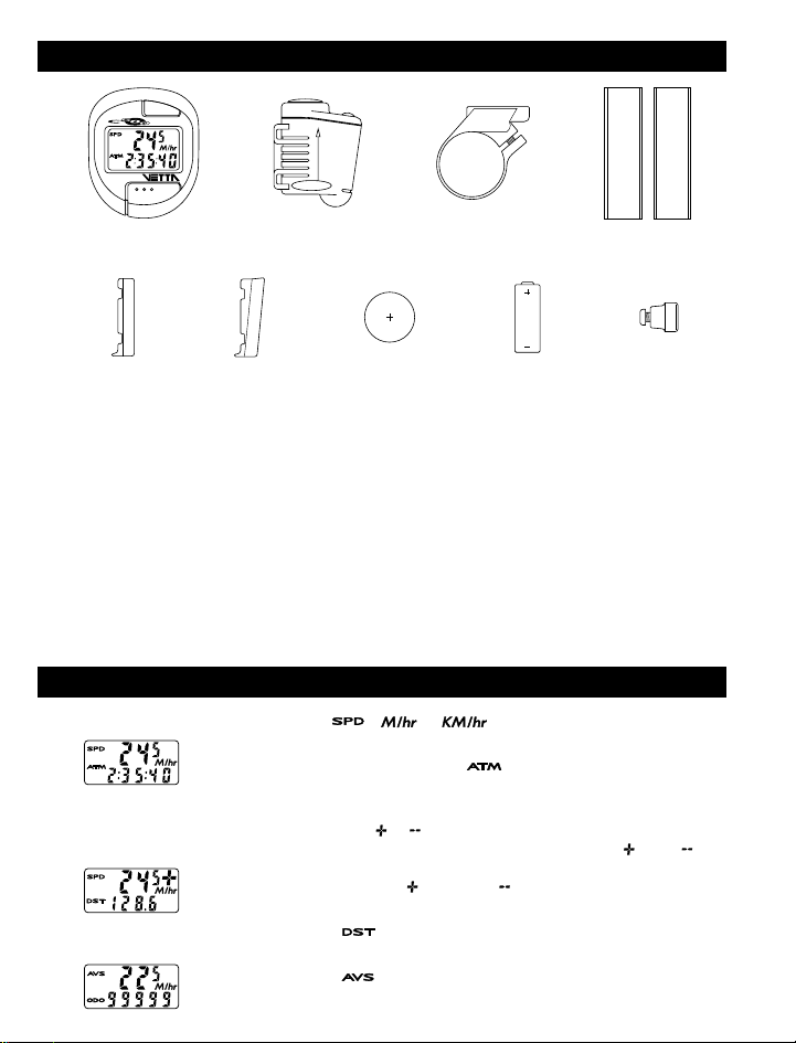
DRAWINGS OF PARTS
UP
MAGNET
Head Unit
Flat Rubber Block Angled Rubber Block Head Unit Battery Transmitter Battery Magnet
Rubber ShimsTransmitter Bracket
LISTING OF FUNCTIONS
SPEEDOMETER ( ) ( or
Tells you your instantaneous speed. Accurate to 0.5 mph or kmph
AUTOMATIC RIDE TIME STOPWATCH ( )
Stopwatch activated by wheel movement, turning on when you ride and off when
you stop. Records true ride time, time spent actually riding, up to 9:59:59.
SPEED COMPARATOR ( or )
Compares current speed to average speed. As you are riding a ( ) or a ( ) will
appear in the upper right hand corner of the display. This will indicate whether
your current speed is faster ( ) or slower ( ) than your current average speed.
This function is automatic, requiring no programming and cannot be disabled.
TRIP ODOMETER ( )
Tells you the distance for your current ride from 0 to 999.9 mi. or km.
AVERAGE SPEED ( )
Your average speed calculated using your true ride time and trip distance.
)

CUMULATIVE ODOMETER ( )
Tells you your cumulative distance for the year from 0 to 99999 mi. or km.
MAXIMUM SPEED ( )
Displays the fastest speed that you have traveled.
DIGITAL 12 HOUR CLOCK
Gives you the time of day in a 12 hour format.
AUTO SHUT DOWN
As a battery saving device, Vetta computers will automatically shut down after
5-10 minutes of non-use. Because it is wireless, once the C-500 has entered the
sleep mode, you must press one of the two buttons to reactivate the unit.
FREEZE FRAME MEMORY (FLASHING DISPLAY)
This feature allows you to store a snapshot of the display for an extended period
of time. This feature is useful at the end of a race, allowing you to hold a record
of your time, distance, average speed and maximum speed while you are cooling
down. While the display is frozen, the computer will continue to update and store
ride information. All information is updated and displayed as soon as the freeze
frame memory is turned off.
ACTIVATE FREEZE FRAME MEMORY
In any mode, press the upper computer key (B) for approximately 1 second. The entire display will flash
indicating that the feature is active. You may now cycle through the functions by pressing the lower key (A).
DEACTIVATE FREEZE FRAME MEMORY
Press the upper computer key (B) to update the display and return to normal operation.
RESET CYCLING FUNCTIONS
In the / mode, press both keys for 2 seconds to clear the , , and displays.
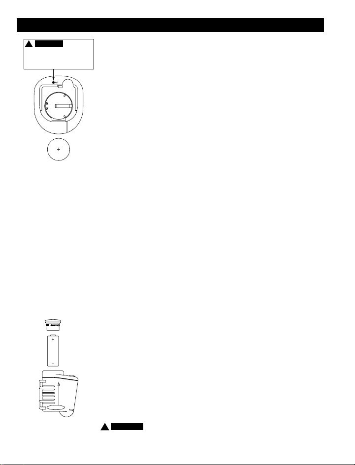
BATTERY INSTALLATION
CAUTION
!
AUTO CLEAR BUTTON
Press for total reset of unit.
All stored data will be erased.
3032 3v Lithium Battery
UP
MAGNET
23A 12v Battery
The head of the C-500 uses a common 3032 3v lithium button cell battery, and
the transmitter uses a common 23A 12v battery. Replacement batteries are
available at most camera shops and from your Vetta retailer. Under normal usage
a battery should last approximately one year.
with cycle computers are caused by dead or weak batteries. If you are having
problems with your computer's operation, check and replace the battery first.
INSTALLATION OF HEAD UNIT BATTERY
STEP 1
Remove the battery cover from the bottom of the computer using a small flat
blade screwdriver.
STEP 2
Install the battery into the battery compartment with the positive (+) side of the
battery facing the compartment door. Be careful when you are installing the
battery not to bend any of the battery contacts.
STEP 3
Press the battery cap firmly into place making sure that the rubber o-ring seal
does not get pinched or distorted as this will compromise the waterproofing of
the unit.
INSTALLATION OF TRANSMITTER BATTERY
The transmitter should come from the factory with the 23A 12v battery installed.
STEP 1
To replace the battery, first remove the battery cap on the top of the transmitter
with a coin. Remove the old battery and dispose of properly.
the inside of the transmitter for corrosion. If corrosion is visible replace the
transmitter with a new unit.
STEP 2
Install a new battery in the transmitter battery compartment with the positive
(+) side facing the opening and reinstall the battery cap.
!
CAUTION Make sure that the battery cap is tight to prevent moisture from
entering the transmitter unit. An improperly installed battery can damage the
NOTE: Most problems that occur
NOTE: Check
 Loading...