

Page 1
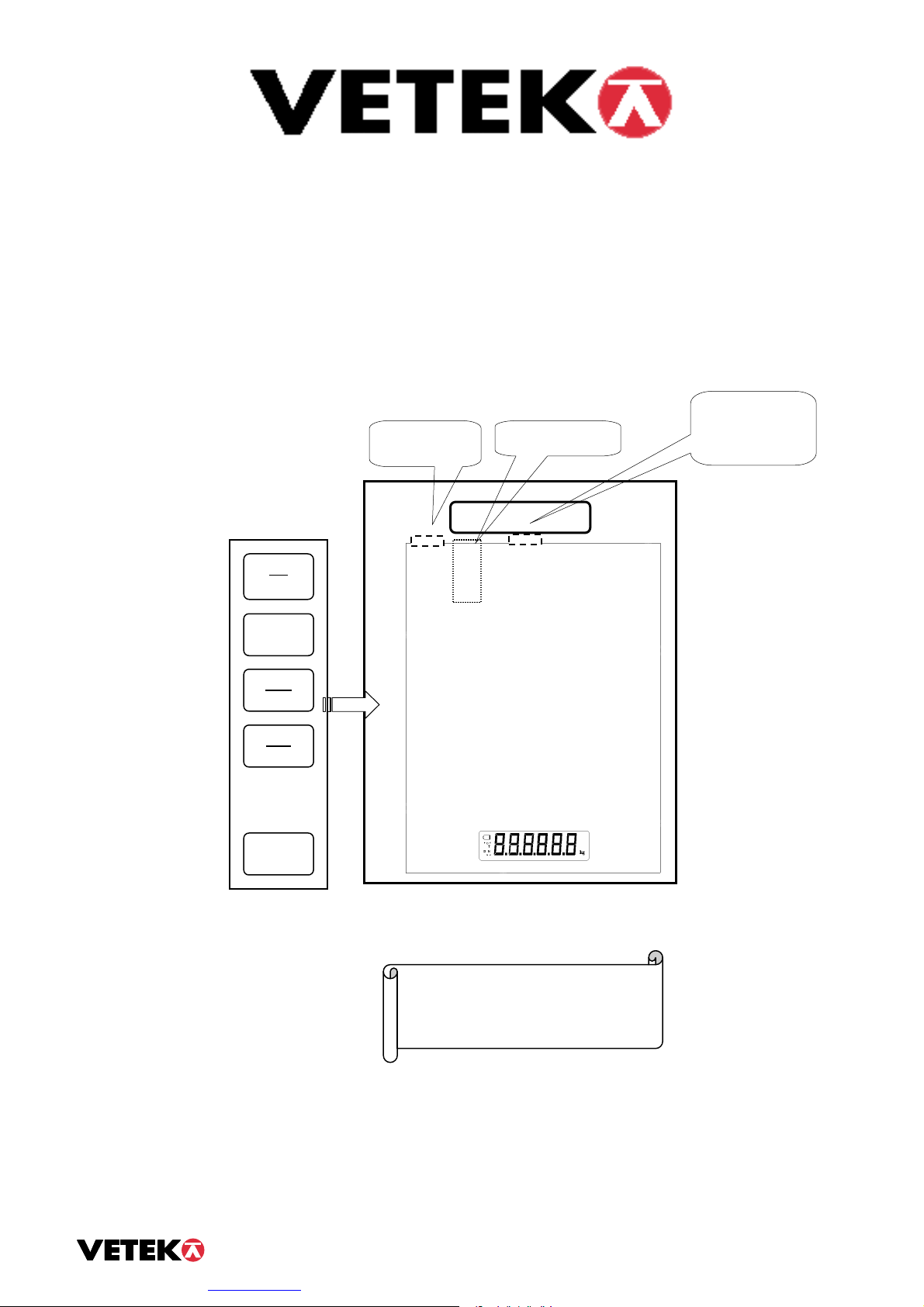
Manual Force Meter Weighingblock VB2-10K
Alkaline battery 9 V
GROSS
ZERO
Note:
- At last page in this manual you will find a short form instruction. Normally the only
instruction shipped together with the Force Meter.
9VDC jack
Calibration switch
ON
PRINT
O
(2,1mm center
NET
OFF
TARE
The Weighingblock is a robust Force Meter. It is
designed for portable use. When transported by car
between different working places we recommend
using of a protected space or a case. This will extend
the interval for service.
Hantverksvägen 15, 76493 Väddö Sweden
Tel +46 176 208 920 info@vetek.com www.vetek.
page 1
Manual_VB2-10K_V1
com
Page 2

Table of contents Page
GROSS
ZERO
Introduction, Keyboard Functions 2
Configuration and Setup Menu. Display 3
Parameters 4
Calibration 5
Specifications and Displayed Error Codes 6
Fault localization and repair 7
Instruction for handling 8
Introduction
Veteks new VB2 series of Weighingblocks are rugged digital Force Meter made in strong aluminum. It comes standard with a large
(.75") LCD screen for easy readout. All setup parameters may be entered via the membrane panel keys. The Force Meter has an
”intelligent” auto power off function.
The Force Meter is developed for general force measuring The setup parameters are altered through the Setup menu while a
few other parameters are altered through the User menu. The configuration section of the manual explains how to use
the five front panel keys to maneuver and save settings in both menus.
The Force Meter is equipped with 9 V alkaline battery. If the battery is not good enough to ensure a correct value the
Force Meter will turn off.
oard functions
Keyb
The calibration switch besides the battery is only for calibration.
ON
PRINT
O
NET
OFF
TARE
Indicator ON
Normally disabled.
Toggles between Gross and Net weight/force display only if a Tare has been established.
Sets Force Meter to display "0" when in Gross mode, and within zero band range. When pushed in
for 3 seconds, the Force Meter switches off.
Used to establish a Tare (zero the Force Meter) while in either Gross mode or
Net mode. This operation cannot be performed at or below Gross zero.
Hantverksvägen 15, 76493 Väddö Sweden
Tel
+46 176 208 920 info@vetek.com www.vetek.
page 2
com
Page 3
Configuration
Setup menu.
To do this configuration you need to have a good acknowledge how a digital electronic Force Meter works. Note: If the
Force Meter fails, it is not always sure the Force Meter needs a configuration.
Except the Normal Meny the Weighingblock has two menus.
The Setup menu, containing most of the indicator's functional Setup parameters, consists of 15 separate menu selections, each with its own
sub-menu of choices.
The User menu, except A5 and A10 containing most of the indicator's serial communication parameters which not are shown in this
manual.
SETUP MENY
1. Turn the power OFF.
2. Press Calibration Switch one time.
3. Turn the indicator ON.
4. The display shows "F1" to indicate that the unit is in Setup menu mode.
5. To move to a new “F” heading, use TARE or ON to move up or down.
6. To move to the selection value, press ZERO once.
7. Increase the flashing digit by pressing lb/kg. Decrease the flashing digit by pressing ZERO.
8. To save the value, press NET.
9. Press O to go back to parameter number.
10. To go back to normal menu press Calibration Switch one time for normal mode.
NOTES ON THE SETUP MENU
There is an F21 sub-menu present that is for FACTORY USE ONLY!
DISPLAY
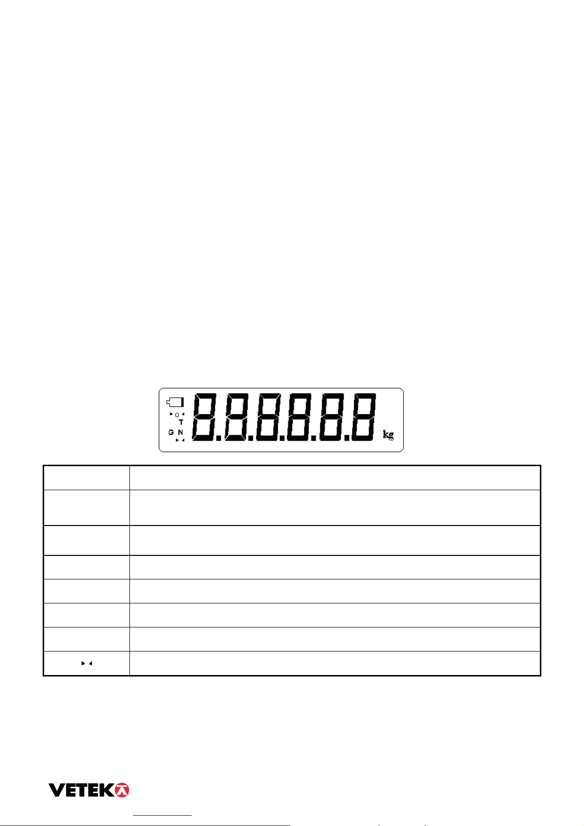
LCD Enunciator MEANING
0 Better known as the “Center of Zero” enunciator, this light is active whenever the displayed
weight/force is within ± 0.25 divisions of true zero.
N
G Indicates that the indicator is displaying gross weight/force.
T Indicates that a tare weight/force has been established in the system.
Indicates that the indicator is displaying net weight/force.
lb, kg Indicates the unit of the displayed weight/force (normally disabled).
bAtt Indicates a low battery condition.
Indicates stable measuring.
VB2 Enunciator Definitions
Hantverksvägen 15, 76493 Väddö Sweden
com
page 3
Page 4
PARAMETER DESCRIPTION CODE/VALUE
F1
Graduations
Specifies number of the Weighingblocks graduations. Value should be consistent
with legal requirements and environmental limits on the useful system resolution.
500 1,000 1,500 2,000
2,500 3,000 4,000 5,000
6,000 8,000 10,000
F2
Span Gain
F3
Zero Track Band
F4
Zero Range
F5
Motion Band
F6
Digital Filter
F7
Overload Limit
F8
Calib. Unit
F9
Display Div.
F10
Decimal Pt.
F16
Zero Calibration
Span Gain is related to A/D integration time. The larger the span gain, the higher the
internal resolution, but the slower the update speed.
Selects the range within which the Force Meter will automatically zero. Note that the
Force Meter must be in standstill to automatically zero. Selections are in Display
Divisions. “d” = graduation
Selects the range within which the Force Meter may be zeroed. Note that the indicator
must be in standstill to zero the Force Meter.
Sets the level at which motion is detected by comparing the present display update
with the previous one. If motion is not detected for two seconds or more, Force Meter
is in standstill and can process a Print or Zero command. Maximum value varies
depending on local regulations.
Averages weight readings to produce higher accuracy. The higher the filter number,
the greater the accuracy but the slower the response time. Choose 4 or 8 unless a very
fast response is needed.
Selects the desired formula which determines the point at which the indicator shows
overload (""). All selections are based on the primary unit selected in F8.
"FS" = Full Force Meter in primary units.
Selects the primary base unit to be used in the calibration process. Also the default
unit for normal operation.
"1" = primary unit is lb. "2" = primary unit is in kg.
Determines the desired weight increments. Value should be consistent with legal
requirements.
Determines location of the decimal point.
Places indicator into the zero calibration routine. Scrolling down with the ZERO key
one level begins the procedure.
25 50 75 100
150 200
0d 0.5d 1d
3d 5d
100% 1.9% 2%
20%
0,25 1d 3d
5d 10d
1 2
4 8
FS FS + 2%
FS + 1d FS + 9d
1
2
1
2
5
0 0,0
0,00
0,000 0,0000
Press ZERO key to begin sequence
F17
Span Calibration
F21
Factory Reset
A5
Disable the lb/kg
Key
A10
Auto Power Off
Period
Places indicator into the span calibration routine. Scrolling down with the ZERO key
one level begins the procedure.
This sub-menu will reset all parameters in the “F” and “A” menu to the default
settings. USE WITH CAUTION!
Allows the lb/kg key to be disabled so that an operator cannot accidentally press the
key and change the displayed units.
"0" = Disable the lb/kg key "1" = Enable the lb/kg key
Selects the auto off time period in minutes:
“Off” = Disabled (Always ON)
Press ZERO key to begin sequence
Press the ZERO key twice to execute.
0
1
1, 2, 4, 10, 20, 60, off
Hantverksvägen 15, 76493 Väddö Sweden
Tel
+46 176 208 920 info@vetek.com www.vetek.
page 4
com
Page 5
Calibration
GROSS
ZERO
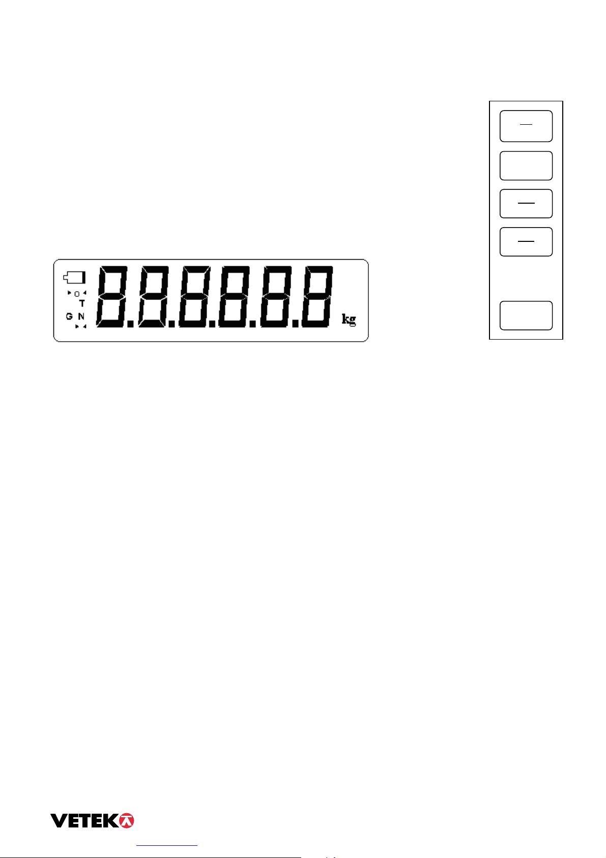
We recommend the Force Meter to be calibrated at yearly intervals.
The minimum test force that can be used is 70% of full-Force Meter capacity.
To calibrate the zero point using the F16 zero calibration procedure:
1. Turn the power OFF
2. Press the Calibration Switch once.
ON
PRINT
3. Turn the power ON and the display will show F1, if not go back to point 1.
4. Scroll to "F 16". Use the TARE or PRINT key to move up or down. (If necessary press O to go back
to parameter number.)
O
5. Press ZERO. The display will momentarily show "C 0" followed by a value. (If necessary press O to
go back to parameter number.)
6. After making sure that there are no weights on the platform, press ZERO to zero out the displayed
NET
value.
7. Press NET
back up to F16. At this time, proceed to the F17 span calibration to complete indicator calibration.
to save the zero point value. The display will show "EndC0"momentarily, and then revert
OFF
TARE
To calibrate the max point using the F17 span calibration procedure:
1. Scroll to "F 17", then press ZERO to enter span calibration menu.
2. The display will momentarily show "C 1" for the span calibration, followed by a value with one flashing digit. This
value will be zero. Place the test force on the Force Meter.
3. Pressing TARE or ON will change the position of the flashing digit.
4. Increase the flashing digit by pressing O. Decrease the flashing digit by pressing ZERO.
5. After setting the exact value, press NET to save the value.
6. If the calibration was successful, the display will show "EndC1" momentarily, and then revert back up to F17.
"Err0" – The calibration test force or the adjusted keyed-in weight is larger than the full capacity of
the Force Meter. Change the calibration test force or check the input data.
"Err1" – Change the calibration test force or check the input data.
"Err2" – The internal resolution of the Force Meter is not high enough to accept the calibration value.
Select a larger parameter for the Span Gain (F2).
7. Press Calibration Switch one time for normal mode.
Tel +46 176 208 920
Hantverksvägen 15, 76493 Väddö Sweden
[email protected] www.vetek.
com
page 5
Page 6
Specifications and displayed error codes.
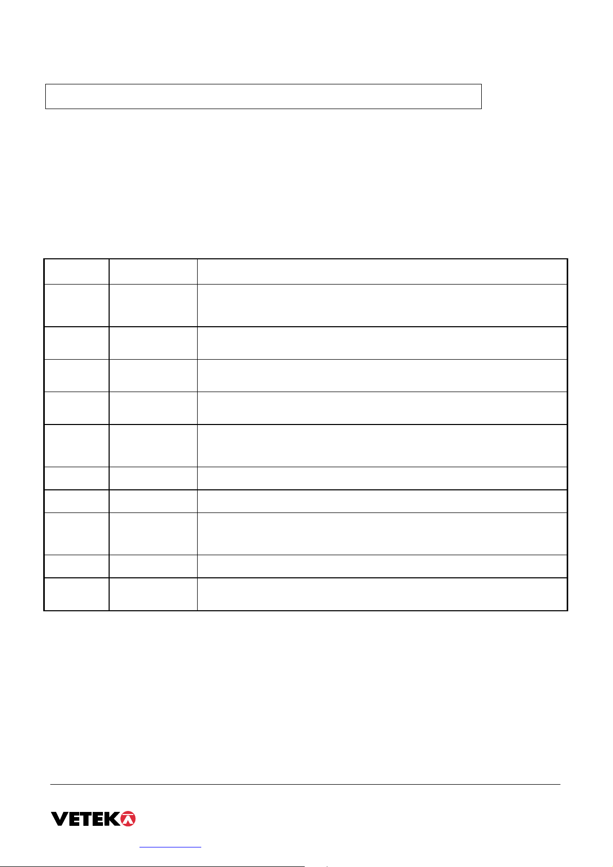
Model Capacity / Graduation Dimension mm Battery Own weight
VB-10K Max 10000 daN / 2 daN 260 x 210 x 54 1 pcs alkaline 9 V 3,2 kg
OPERATOR INTERFACE
Display 0.75" (19 mm) 7-segment, Liquid Crystal, 6-Digit
Additional Symbols Net, Gross, Stable, Tare, lb, kg, Zero
Keyboard 5-key flat membrane panel
ENVIRONMENTAL
Operating Temperature -10 to +40 grad C
Storage Temperature -25 to +70 grad C
Displayed error codes.
DE MODE MEANING / POSSIBLE SOLUTION
CO
bAtt Normal Operating
Err 0 Span Calibration
Err 1 Span Calibration
Err 2 Span Calibration
Err 3 All Modes Non-volatile memory read error. One or more setup parameters have been lost.
Err 4 All Modes Non-volatile memory writes error. The unit needs service.
Err 5 Key-in Span
Err 7 Initialization No reading from the ADC. Make sure there is a load cell(s) connected to the indicator at start-up.
Err 9 Normal Operating
Normal Operating
Mode
Mode
Mode (F17)
Mode (F17)
Mode (F17)
Calibration Mode
(F20)
Mode
Gross Overload. A force greater than the rated capacity has been applied to the Force Meter. Remove the
force from the platter or try re-calibrating the Force Meter. Otherwise, check for a bad load cell connection
or possible load cell damage due to overloading.
Indicates a low battery condition.
Keyed-in force value is larger than full-Force Meter capacity. Use a smaller test force or check keyed-in
value.
Keyed-in force value is less than 1% of full-Force Meter capacity. Use a larger test force or check keyed-in
value.
There is not enough load cell signal to produce the internal counts necessary to properly calibrate the Force
Meter. First check all load connections. Use F16 mode to view internal counts. See Appendix C for more
information.
You have attempted to enter a zero value for C1. Enter a known calibration value greater than zero.
Span calibration value has been lost. Re-calibrate the Force Meter.
Hantverksvägen 15, 76493 Väddö Sweden
+46 176 208 920 info@vetek.com www.vetek.
Tel
page 6
com
Page 7

Fault localization and repair.
Fault localization
If the Weighingblock is “dead”.
1. Check the battery. Use only a 9 V alkaline battery.
If the Force Meter starts but the display shows wrong.
1. Calibrate the Force Meter.
2. If it not works.
3. The Force Meter must be demounted.
Demounting.
1. Demount the Weighingblock carefully.
2. Check the inside visually. Look for bad cables and connections.
3. If needed, clean the PC-board.
If the Force Meter shows F1
1. Probably has the Calibration Switch been changed to calibration mode?
2. Reset to normal mode.
3. Press OFF and ON.
Check the Loadcell
1. Check the Loadcell with a universal volt instrument, see encl table. The pin close to the corner is number 1.
Pin Description
1 Out +5VDC
2 In +
3 Out 0 VDC
Check the excitation voltage, it should be aprox 5 VDC.
The
output from the Loadcell (pin 2 and 4) will increase from
aprox. 0 to 10 mV for the capacity range.
4 In -
If some parameters by mistake has been changed.
1. If only the first,F1, has been changed. Set back to right value in accordance to the table.
2. If many parameters has been changed. Check all parameter values. Probably it is necessary to calibrate
the Weighingblock.
Hantverksvägen 15, 76493 Väddö Sweden
+46 176 208 920 info@vetek.com www.vetek.
Tel
page 7
com
Page 8
Instruction for handling Weighingblock VB2-10K
ON
NET
GROSS
OFF
ZERO
This instruction is for the user of the Force Meter. It is the last site in the complete manual. Hopefully is this the only
needed information. For complete information, contact you wholesaler, Vetek AB or download it from our web site
http://www.vetek.net
LCD
MEANING
Enunciator
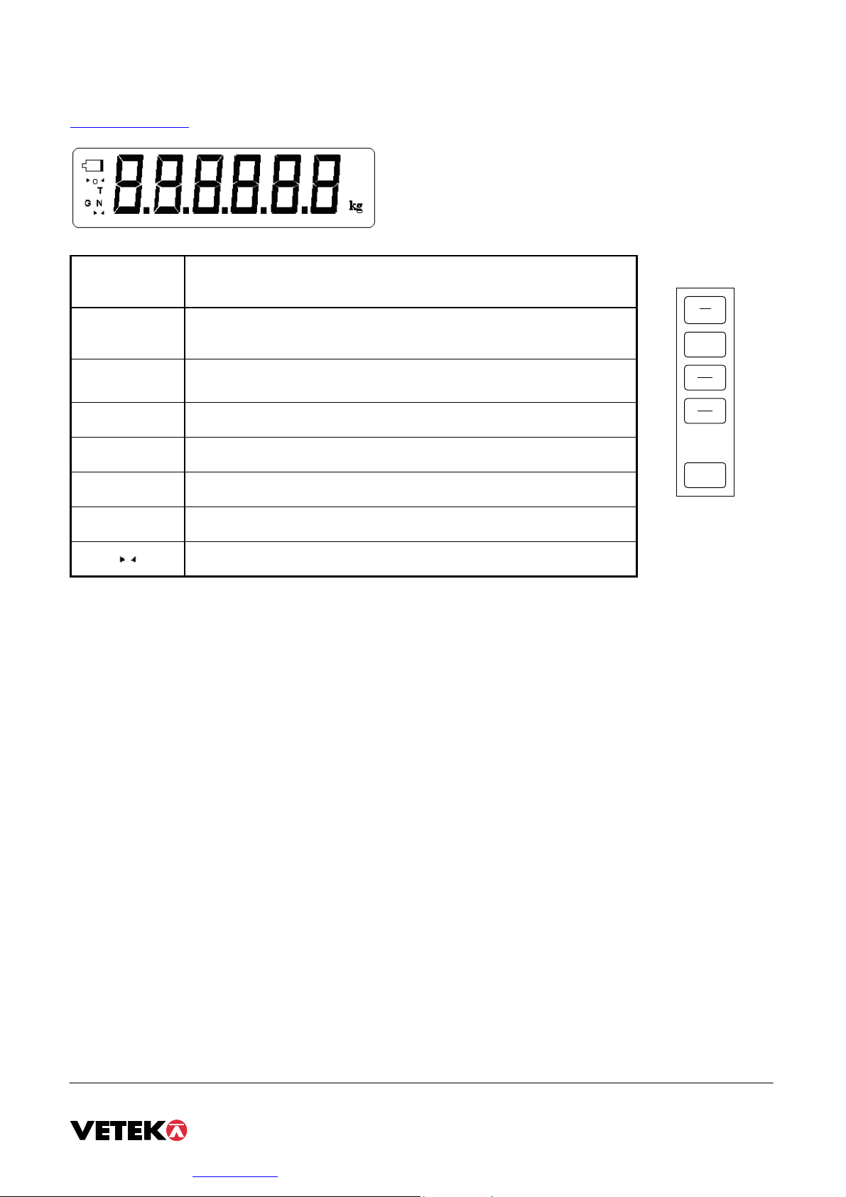
0 Better known as the “Center of Zero” enunciator, this light is active
PRINT
whenever the displayed weight is within ± 0.25 divisions of true zero.
N
Indicates that the indicator is displaying net weight/force.
G Indicates that the indicator is displaying gross weight/force.
T Indicates that a tare weight/force has been established in the system.
TARE
Lb/kg Indicates the unit of the displayed weight/force (normally disabled).
bAtt Indicates a low battery condition. Replace the alkaline battery.
Indicates stable weighing.
VB2 Enunciator Definitions Shown above is the LCD display. Before reading the value the stable indicator must be ”on”.
If not wait a few seconds until it appears.
Handling
1. Press ON to start the Force Meter.
2. If necessary, press ZERO to obtain a weight/force reading of zero.
3. Press OFF to switch off the Force Meter. Hold 3 seconds.
4. The Force Meter switches off automatically after 20 minutes when not in use
O
Force measuring.
1. Unload Force Meter and press ZERO.
2. Place the object on the Force Meter’s platter and allow the force indication to stabilize. If the item force exceeds the
Force Meter’s capacity, it displays “”. Press TARE to zero the Force Meter. The display shows zero force
and turns the NET enunciator on.
3. NET/GROSS toggles between Gross and Net weight/force display only if a Tare has been established.
General advice
When the Force Meter is not in use and is transported between different working places we recommend to use a case or any
other protection against vibrations and other hard environmental conditions. Protect the Force Meter with a transparent
plastic bag if there is any risk of leakage or when working in a wet environment.
page 8
Hantverksvägen 15, 76493 Väddö Sweden
Tel
+46 176 208 920 info@vetek.com www.vetek.
com
 Loading...