

Page 1

Vetek Weighing AB
www.vetek.com
JWL Service Manual
May not be reproduced in any form without written permission
PAGE
0
JWL Series
Service Manual
Page 2

Vetek Weighing AB
www.vetek.com
JWL Service Manual
May not be reproduced in any form without written permission
PAGE
1
I.
Contents
Assembly drawing
1
2
1 – 1 Explosive view (JWL) 2
1 – 2 List of parts (JWL) 3
1 – 3 Block diagram of electronic structure 4
1 – 4 Wiring diagram 5
2. Troubleshooting procedure 6
2 – 1 Troubleshooting flow 6
2 – 2 Troubleshooting table 7
2 – 3 Confirmation of application environment 7
2 – 4 Simple inspection of electric circuit 8
2 – 5 Performance inspection 8
3. Maintenance and setting 9
3 – 1 Maintenance flow 9
3 – 2 Model setting 9
4. Setting of parameters 10
4 – 1 Parameter setting 10
4 – 2 Description of parameter values 11
4 – 3 Unit setting 13
5. Linear calibration 17
6. Single point calibration 19
7. Error message list 21
8. External interface 22
8 – 1 RTC function setting 22
8 – 2 Signal output pins of three-in-one board 24
8 – 3 Single option 24
8 – 4 Two options 34
8 – 5 RS232 output format 36
9. Others 38
10. Circuit diagram 41
10 – 1
CPU, peripheral and other circuits
41
10 – 2
LCD circuit 42
10 – 3 Applicable mainboard version and software version 42
Page 3
Vetek Weighing AB
www.vetek.com
JWL Service Manual
May not be reproduced in any form without written permission
PAGE
2
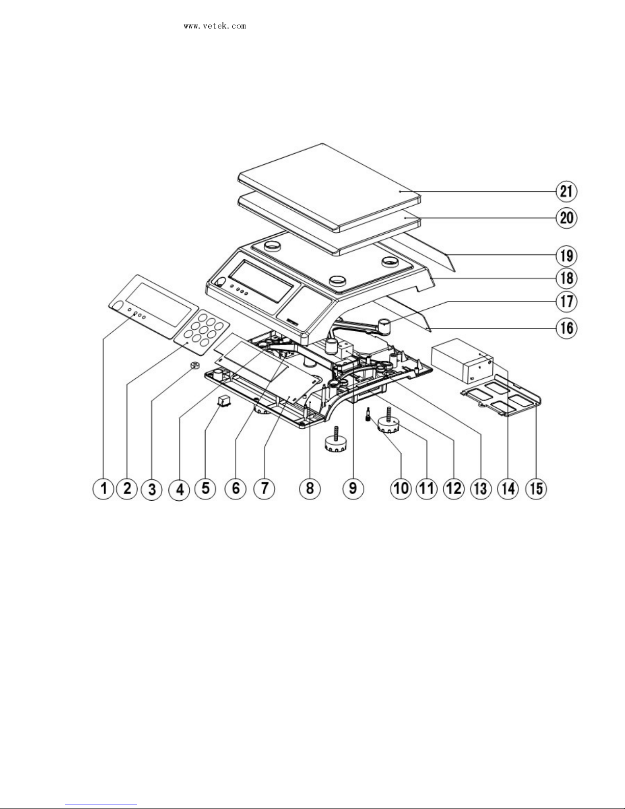
1. Assembly Drawing
1 – 1 Explosive view
Page 4
Vetek Weighing AB
www.vetek.com
JWL Service Manual
May not be reproduced in any form without written permission
PAGE
3
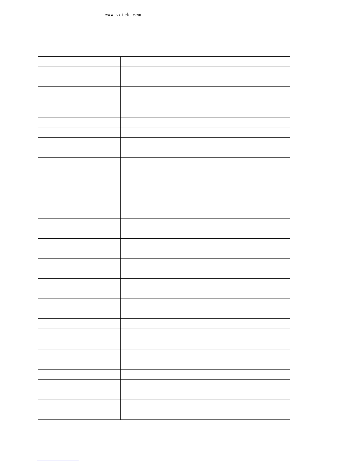
1-2 List of parts
No. Name Quantity Part No.
Material No.
1 xm JWL-
Chinese
front panel
1 JWL-1 21-1925-0100
2 xm key 1 JWL-2 21-0506-0100
3 xm level meter 1 JWL-3 02-0108-0003xm(14mm)
4 Xm transformer 1 JPL-4 61-0003-0400
5 Xm switch 1 JWL-5 60-0000-0000xm
6 Xm power socket 1 JWL-6 80-0125-0000
7 xm semi-
finished
JWL board
1 JPL-7 60-0503-0001xm
8 Xm lower cover 1 JWL-8 02-0000-6020
9 xm lower support 1 JWL-9 10-0425-0100
10
Xm screw for
transport protection
1 JPL-10
31-0404-0000xm
11 Xm rubber levelers 4 JWL-11
01-0100-0030
12 xm RS232 board 1 JCL-12
80-0900-2200xm
13-1 xm sensor -
Chung
Yuen 3k
1 JWL-13
51-0400-0400xm
13-2 xm sensor -
Chung
Yuen 5k
1 JWL-13
51-0410-0000
13-3 xm sensor-
Chung
Yuen 10k
1 JWL-13
51-0410-0010
13-4 xm sensor -
Chung
Yuen 20k
1 JWL-13
51-0410-0020
13-5 xm sensor -
Chung
Yuen 40k
1 JWL-13
51-0410-0040
14 Xm storage cell 1 JWL-14
61-0201-0098xm
15 Xm cell cover 1 JWL-15
02-0000-6030
16 Xm rear PCB 1 JPL-16
80-0126-0010
17 xm upper support 1 JWL-17
10-0425-0000
18 xm upper cover 1 JWL-18
02-0000-6010
19 xm rear panel 1 JWL-19
20-0000-6040
20
xm plastic
down-warped pan
1 JCL-20
02-0000-6040
21
xm stainless steel
down-warped pan
1 JCL-21
12-0000-1200
Page 5
Vetek Weighing AB
www.vetek.com
JWL Service Manual
May not be reproduced in any form without written permission
PAGE
4
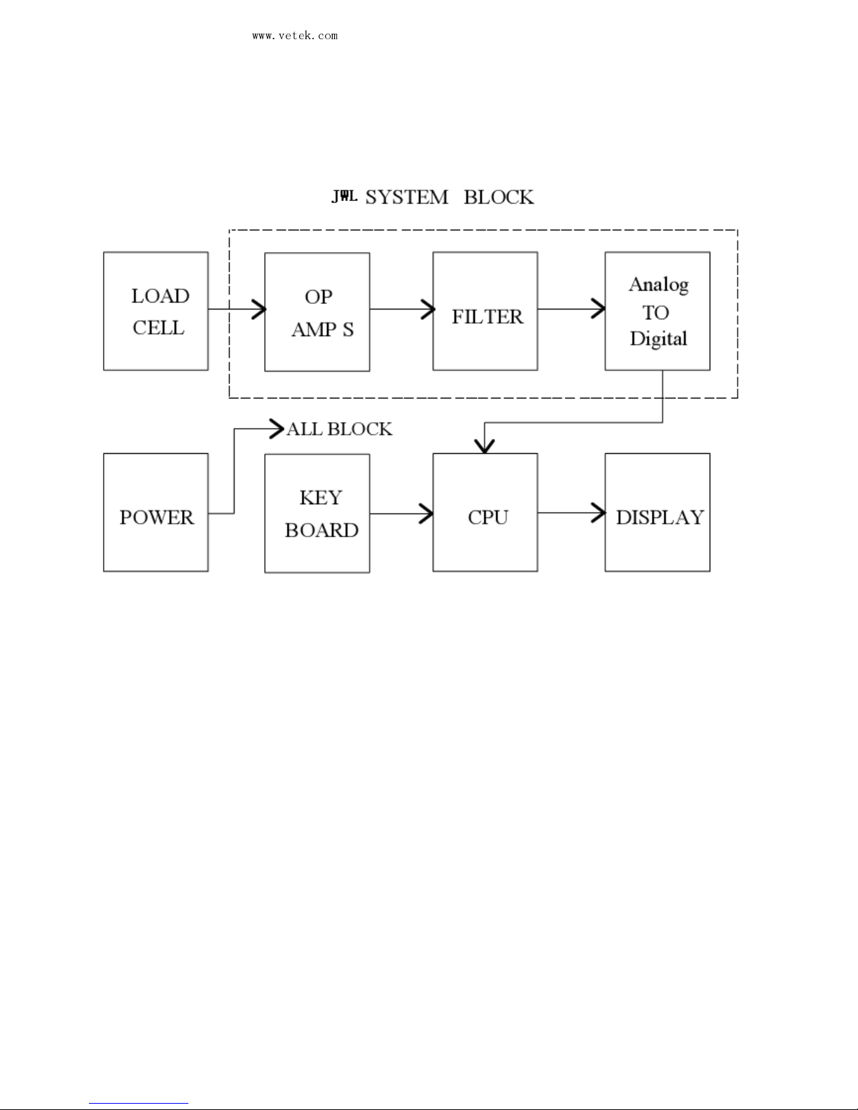
1 – 3 Block diagram of electronic structure
Page 6
Vetek Weighing AB
www.vetek.com
JWL Service Manual
May not be reproduced in any form without written permission
PAGE
5
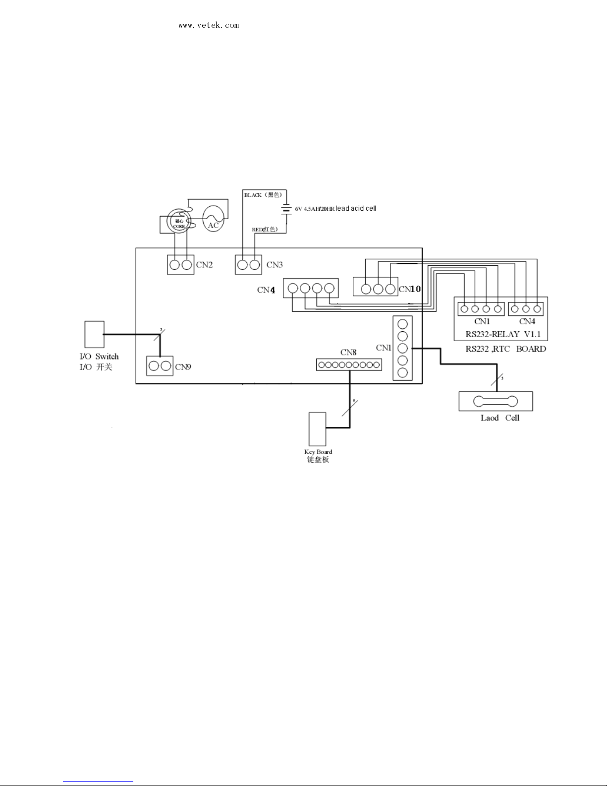
1 – 4 Wiring diagram(圖中中文應去除)
Page 7
Vetek Weighing AB
www.vetek.com
JWL Service Manual
May not be reproduced in any form without written permission
PAGE
6
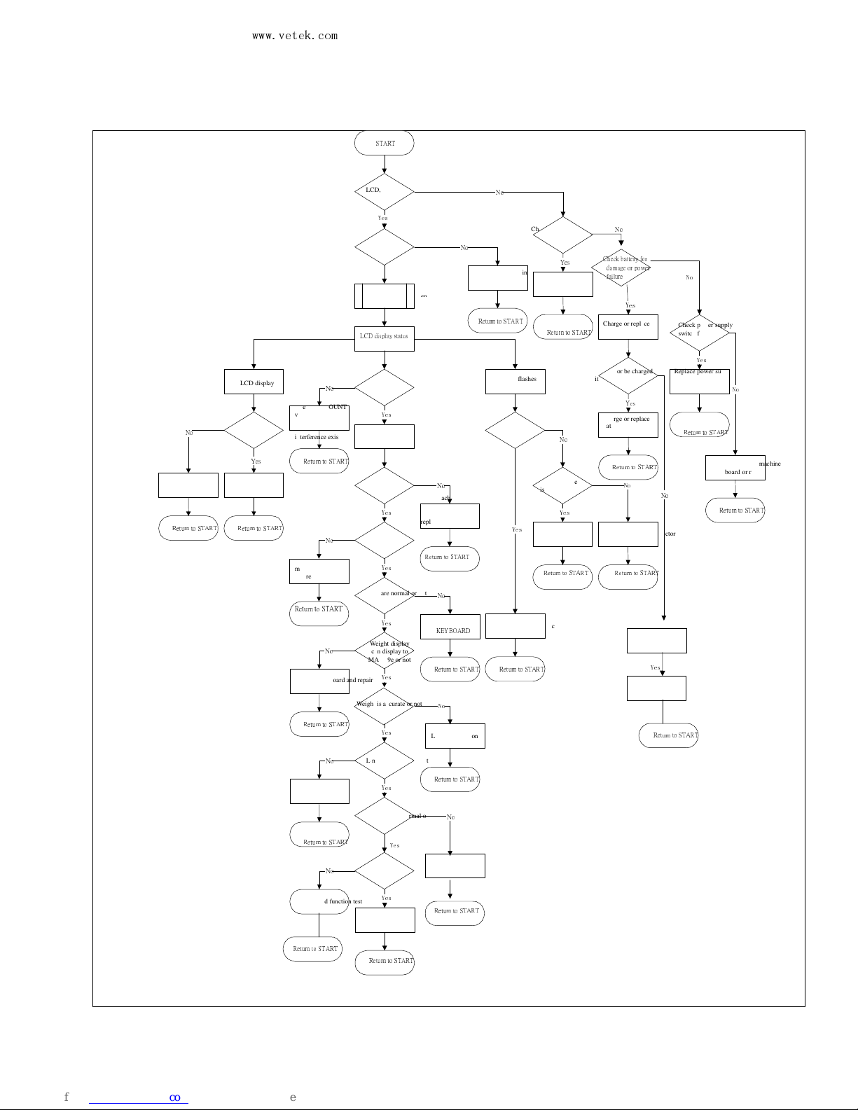
2. Troubleshooting Procedure 2– 1 Troubleshooting flow
START
LED acts
or not
LCD, backlight, buzzer,
LCD displays completely or not
Yes
LCD display status
Cannot zero or
STABLE flashes
LCD display Err5
Display weight
Check for AD
internal
COUNT value
Replace machine board
and repair
Yes
No
Adjust AD value
Transport protecti
ve screw
is disassembled or not
Object interference exists
near scale pan or not
Remove interfering object
Yes
No
Recalibrate zero point Remove transport protector
R
eturn to START
R
eturn to START
R
eturn to START
R
eturn to START
Yes
No
R
eturn to START
Zero point, weighing
is stable or not
Keys are normal or not
Yes
Yes
Weight display
can display to
MAX+9e or not
Yes
Weight is accurate or not
Yes
Linearity is good or not
Can weigh or not
Yes
Unbalanced load is normal or not
Residual creep exists
Yes
Yes
Replace machine board, and repair
or replace LOAD-CELL
No
R
eturn to START
R
eplace
machine board,
and repair,
interference
exists or not
R
eturn to START
No
Can z
ero or not
Yes
Check AD COUNT
value for instability,
replace machine
board, and repair,
interference exists or
not
R
eturn to START
No
Check machine board or
replace
KEYBOARD
R
eturn to START
No
Replace machine board and repair
R
eturn to START
No
Linear calibration
R
eturn to START
No
Linear calibratio
n
R
eturn to START
No
Correct error at the
four corners
R
eturn to START
No
Check LOAD
-CELL
for failure
Return to START
Yes
Performance and function test
No
Check battery wiring
for loosening
Check power supply
switch for failure
No
Connect battery wiring
Return to START
No
Yes
Check battery for
damage or power
failure
Charge or replace battery
Yes
Can it work or be charged
with AC power supply
Charge or replace
battery
Yes
Check transformer for
damage
No
Return to START
Yes
R
eturn to START
No
Replace power supply
switch
R
eturn to START
Yes
Check, repair machine
board or replace it
R
eturn to START
No
Check, repair machine
board or replace it
Return to
START
No
Replace transformer
Return to START
Page 8
Vetek Weighing AB
www.vetek.com
JWL Service Manual
May not be reproduced in any form without written permission
PAGE
7
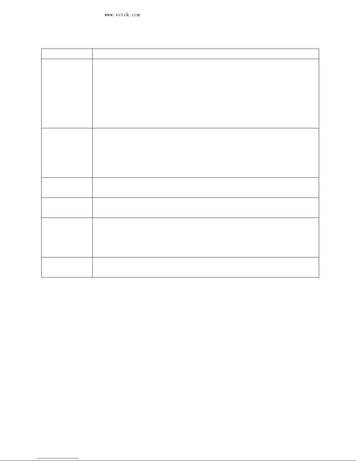
2– 2 Troubleshooting table
Error message
Causes
LCD,
backlight board
or
buzzer
does not work
1. Cell or transformer fault
2. Power switch fault
3. Power circuit fault
4. LCD or related LCD circuit fault
5. Backlight board or backlight related circuit fault
6. Buzzer fault or buzzer circuit fault
7. CPU or oscillating circuit fault
AC current or
cell can’t be
used.
1. Power socket fault
2. Transformer fault
3. Cell fault
4. Power circuit fault
5. Main board fault
Err5 1. Overload (max weighing +9e)
2. Too high or inaccurate calibrated COUNT value.
Cell sign 1. Insufficient cell voltage or cell failure
2. Main board fault
Instable
indication
1. The pan is interfered by any article.
2. There is strong wind or vibration nearby.
3. The cell voltage is insufficient.
4. There is external electromagnetic interference.
Bad linearity 1. The pan is interfered by any article.
2. Bad L/C
2– 3 Confirmation of the application environment
a. Is there a strong wind in the workplace?
b. Is there vibration or instability in the workplace?
c. Is there any article on the pan?
d. Is the stainless steel pan placed on the tray?
e. Has the screw for transport protection been removed?
f. Is the scale set on a horizontal plane?
2 –4 Simple inspection of electric circuit
a. Check if the power supply is normal
Page 9
Vetek Weighing AB
www.vetek.com
JWL Service Manual
May not be reproduced in any form without written permission
PAGE
8
1. Is the voltage 5V at both E+ and E- terminals? Check whether the CPU supply is normal.
b. Check the signal input
1. Check if the outputs from S+ and S- terminals to G change in accordance with the weight on
the pan.
c. Check the digital signals
(1) Check if there is oscillation in Y1’s output pin.
(2) Check if there is oscillation in Y2’s output pin.
2 – 5 Performance Inspection
a. Repetitiveness
Put the weight of two thirds of the load on the pan for five times , the indication difference
between different times should be less than or equal to one division value.
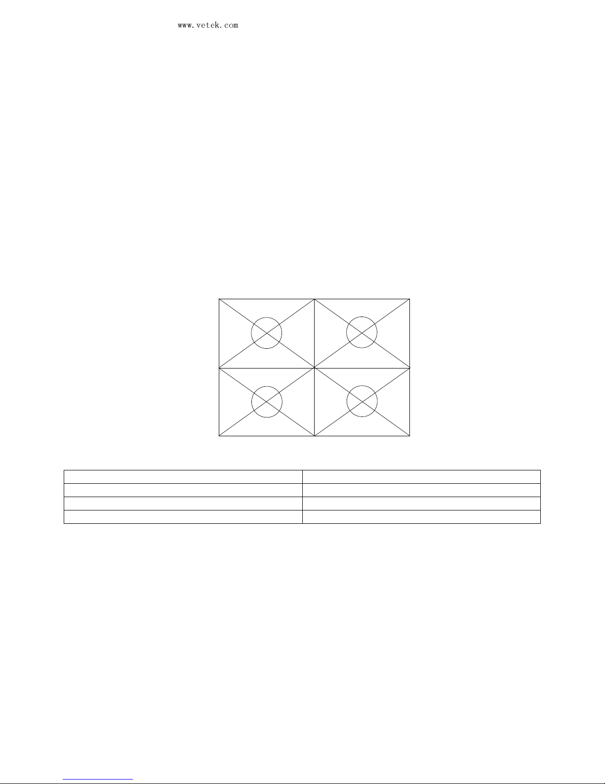
b. Unbalanced loading error
Put the weight of one third of the load on the pan (as shown in the figure). Check if the figure is
precise. The indication difference between the four corners should be less than or equal to one
division value.
a
b
c
d
e
c. Linearity
Load conditions Permissible error
Idle ~ one third of the load 0 e
One third of the load ~ two thirds of the load 1 e
Two thirds of the load ~ full load 2 e
Page 10
Vetek Weighing AB
www.vetek.com
JWL Service Manual
May not be reproduced in any form without written permission
PAGE
9
3. Maintenance and Setting
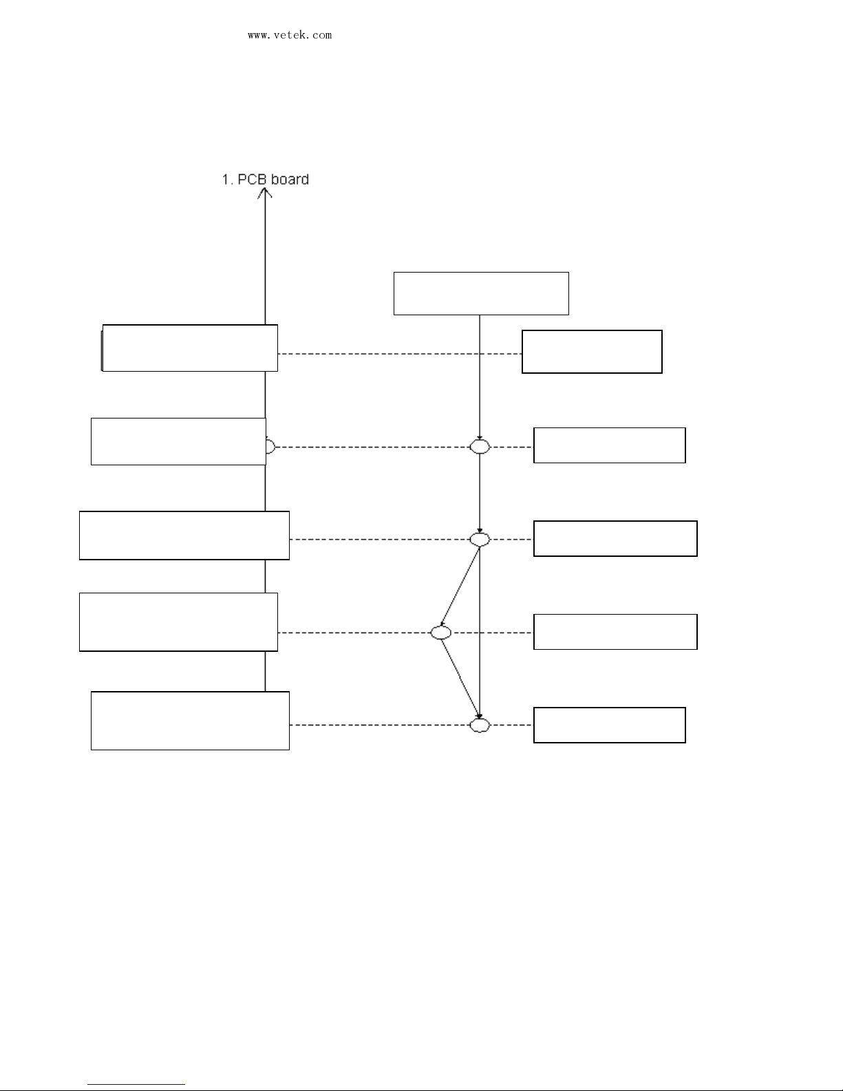
3 – 1 Maintenance flow
3 –2 Model setting
Model setting: Press MR to turn on the unit (the LCD will display 3.0000) and then press UNIT
to select the unit model (for example:1.50000, 3.0000, 6.0000, 7.5000, 15.0000, 30.000 ).
Press G/N and the unit will display “dIu-01” and enter accuracy selection. Press UNIT to
select from diu-01 (1/30000), diu-02 (1/15000), diu-03(1/6000), diu-04 (1/3000), etc. and then
press G/N to store the setting and return to the weighing mode.
Refer to Page 9
Refer to Page 17
Refer to Page 19
Refer to Page 10
Refer to Page 8
Change LOAD-CELL
Model setting
Linear calibration
Single point calibration
Parameter setting
Performance inspection
Page 11
Vetek Weighing AB
www.vetek.com
JWL Service Manual
May not be reproduced in any form without written permission
PAGE
10
4. Setting of Parameters
4-1 Parameter setting
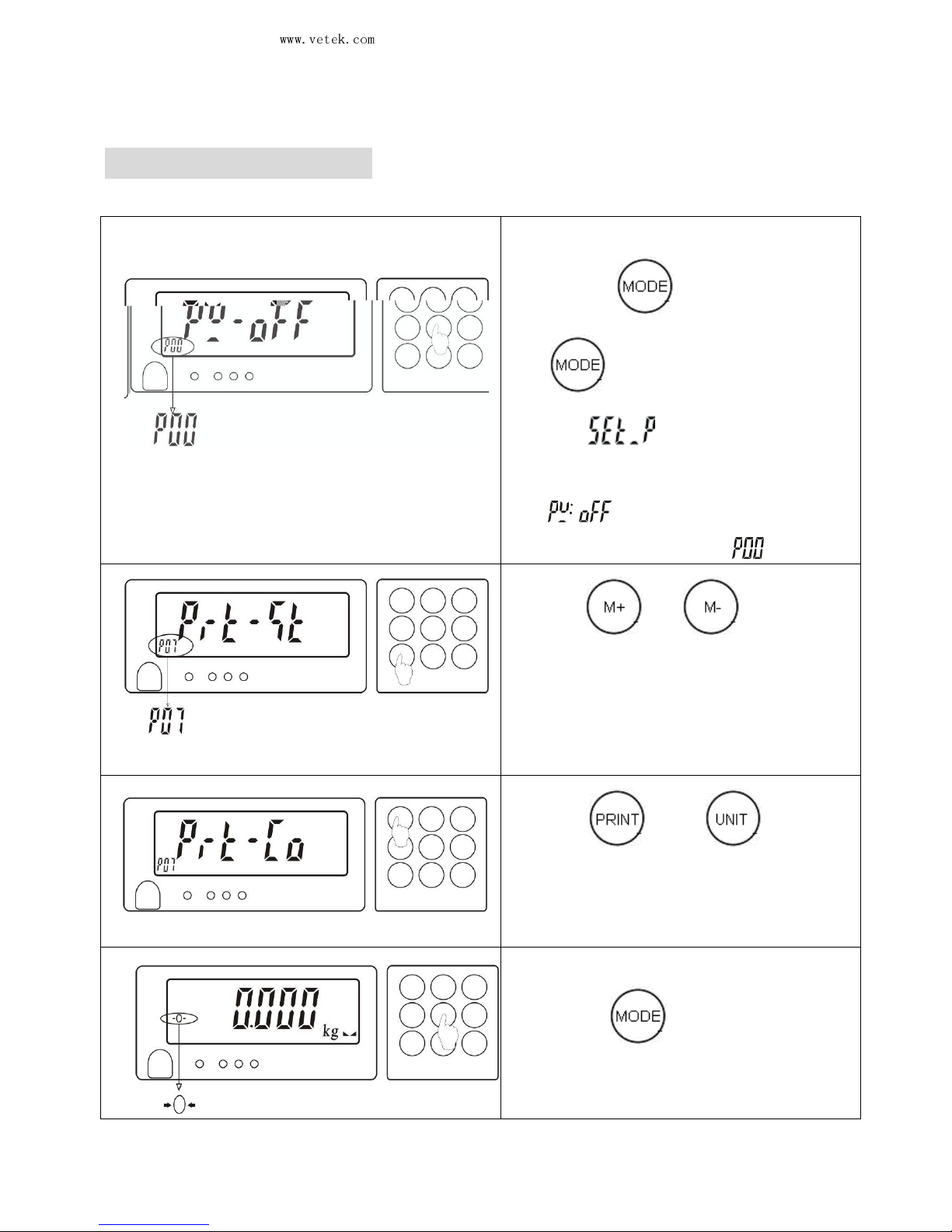
(1). In weighing mode, pre
ss and hold
down
for 3s or press
and release it till
the unit is
on.
will appear first and
then a parameter value such as
” ”
will appear, accompanied
by an auxiliary sign .
(2). Use or
to select the
parameter items (as sh
own in the
table below).
(3). Use or
to select
the values of parameters.
(4).
When the setting is completed,
press
to store the setting
and return to the weighing mode.
Page 12
Vetek Weighing AB
www.vetek.com
JWL Service Manual
May not be reproduced in any form without written permission
PAGE
11
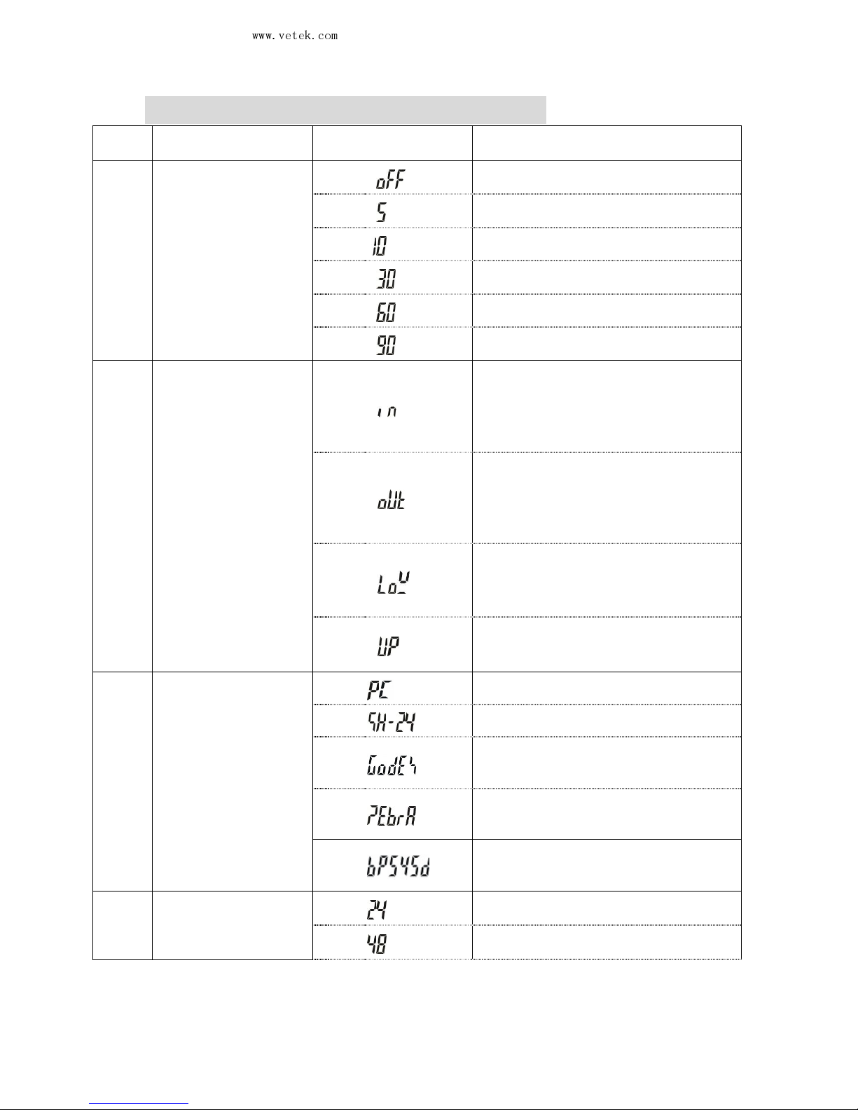
4-2 Description of parameter values
Item
Function
Display
Description
P00
Automatic turn-off
will be
executed when the
weight is smaller
than 9 divisions.
☆
No setting
5 min
10 min
30 min
60 min
90 min
P01
Buzzer beep
There will be an acoustic warning
when the weight of the material is
between the preset upper and lower
limits (including the upper and lower
limits).
There will be an acoustic warning
when the weight of the material is
beyond the preset upper and lower
limits and the weight is more than 20
divisions.
There will be an acoustic warning
when the weight of the material
is less
than the preset lower limit and the
weight is more than 20 divisions.
☆
There will be an acoustic warning
when the weight of the material
exceeds the preset upper limit.
P02
Printer selection
☆
PC output
Dot-matrix
Automatic sticking, paper size:
5cm*3cm
Automatic sticking, paper size:
5cm*3cm
Automatic sticking, paper size:
5cm*3cm
P03
RS-232
transmission rate
The transmission rate is 2400
The transmission rate is 4800
Page 13
Vetek Weighing AB
www.vetek.com
JWL Service Manual
May not be reproduced in any form without written permission
PAGE
12
☆
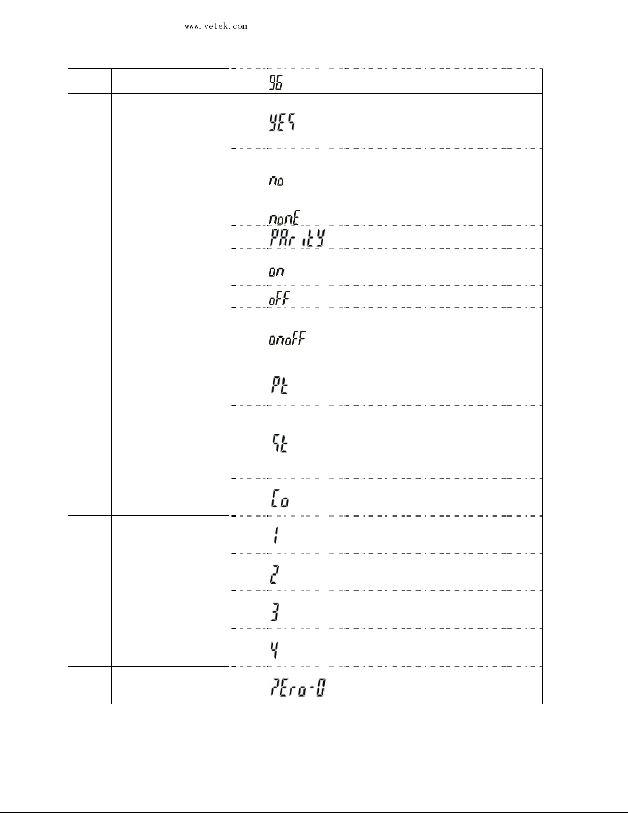
The transmission rate is 9600
P04
Turn-on or off of
the weight check
memory
Automatic turn-
on of the check
mode
when the unit is turned on
next time.
☆
No automatic turn-
on of the
check mode
when the unit is
turned on next time.
P05
Parity check
☆
No parity.
The parity can be odd or even.
P06
Backlight selection
Backlight display will be on
for
the whole process
No backlight display
☆
Backlight display
will be on
when the weight is greater t
han
9 divisions.
P07
Printing mode
selection
Manual printing
☆
Stable printing (the next
printing
will be made only when the
indication is returned to zero.)
Continuous printing
P08
Filter grade
selection
☆
Worst vibration resistance
Average vibration resistance
Good vibration resistance
Best vibration resistance
P09
Zero indication
range
☆
No restriction on the zero
indication
Page 14
Vetek Weighing AB
www.vetek.com
JWL Service Manual
May not be reproduced in any form without written permission
PAGE
13
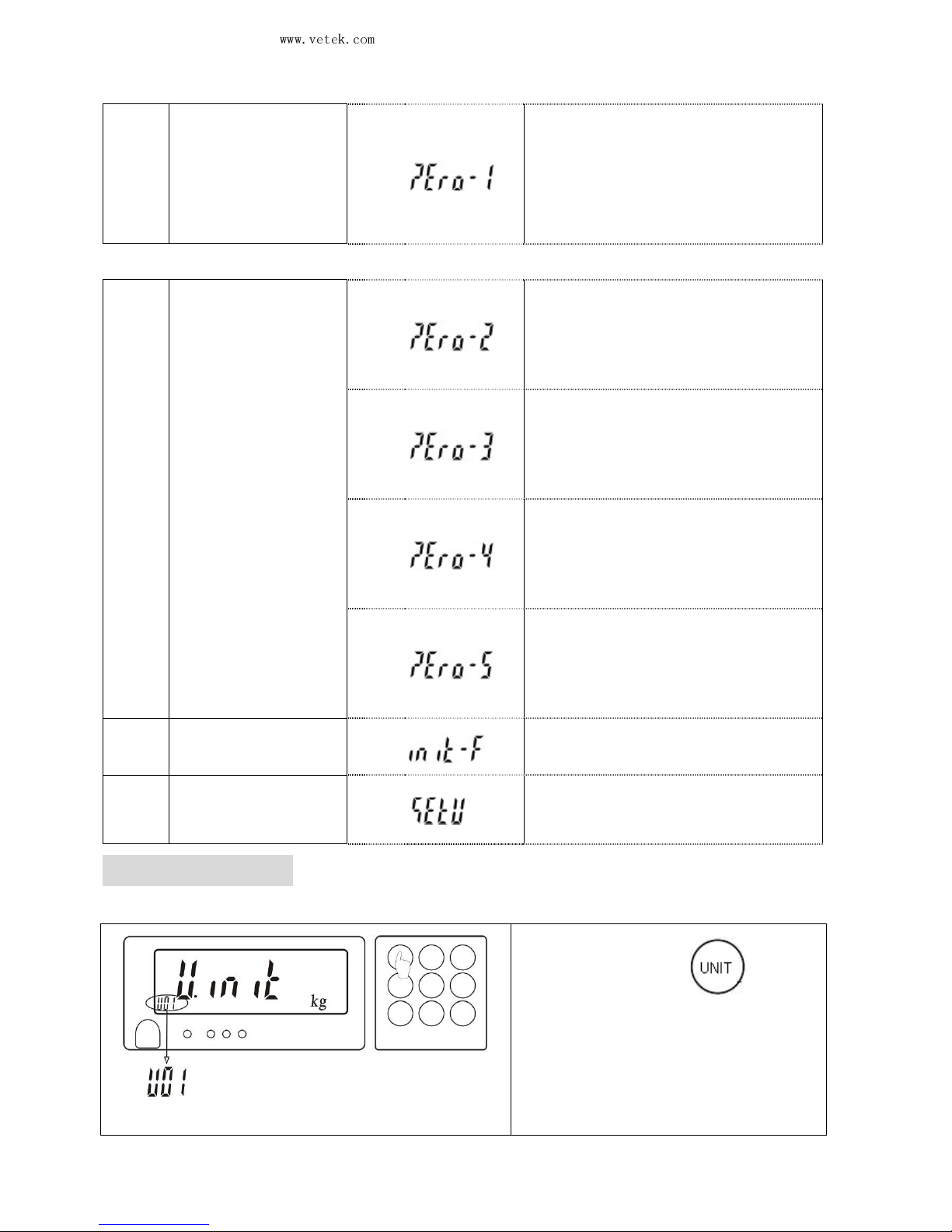
At a zero
indication, only when
at least 2 divisions
or above is
put on the pan will a value be
indicated.
At a zero indication, only when
at least 3 divisions
or above is
put on the pan will a value be
indicated.
At a zero indication,
only when
at least 4 divisions
or above is
put on the pan will a value be
indicated.
At a zero indication,
only when
at least 5 divisions
or above is
put on the pan will a value be
indicated.
At a zero indication
, only when
at least 6 divisions
or above is
put on the pan will a value be
indicated.
P10
Factory initialized
setting
It is a factory set value.
P11
Unit setting
The specific operation is as
follows:
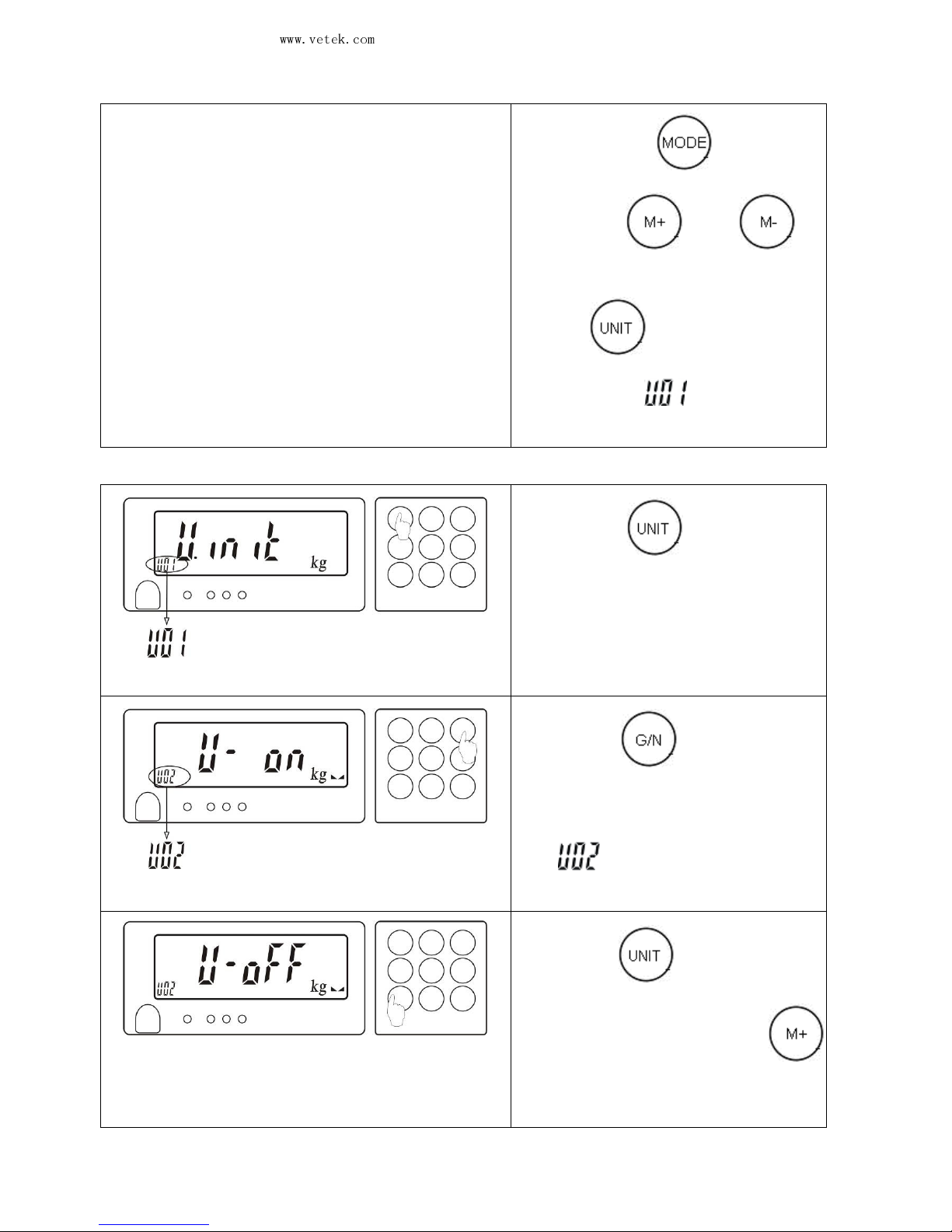
4-3 Unit setting
(1). Mode 1: press
to turn
on the unit till the left picture
appears.
Mode 2: in the weighing
Page 15
Vetek Weighing AB
www.vetek.com
JWL Service Manual
May not be reproduced in any form without written permission
PAGE
14
mode, press for
about
3s, press or
to
select the parameter P11
and
press to
enter the left
picture with
appearing on
the lower left corner.
(2). Press
to select the
unit from g\ kg\ lb\ jin-liang
for
the scale.
(3). Press
to store the
select
ion and switch to the
setting of unit for use, with
appearing on the
lower
left corner.
(4). Press t
o switch the
unit for use. Press
to select turn-on or turn-off
of
this unit.
Page 16
Vetek Weighing AB
www.vetek.com
JWL Service Manual
May not be reproduced in any form without written permission
PAGE
15
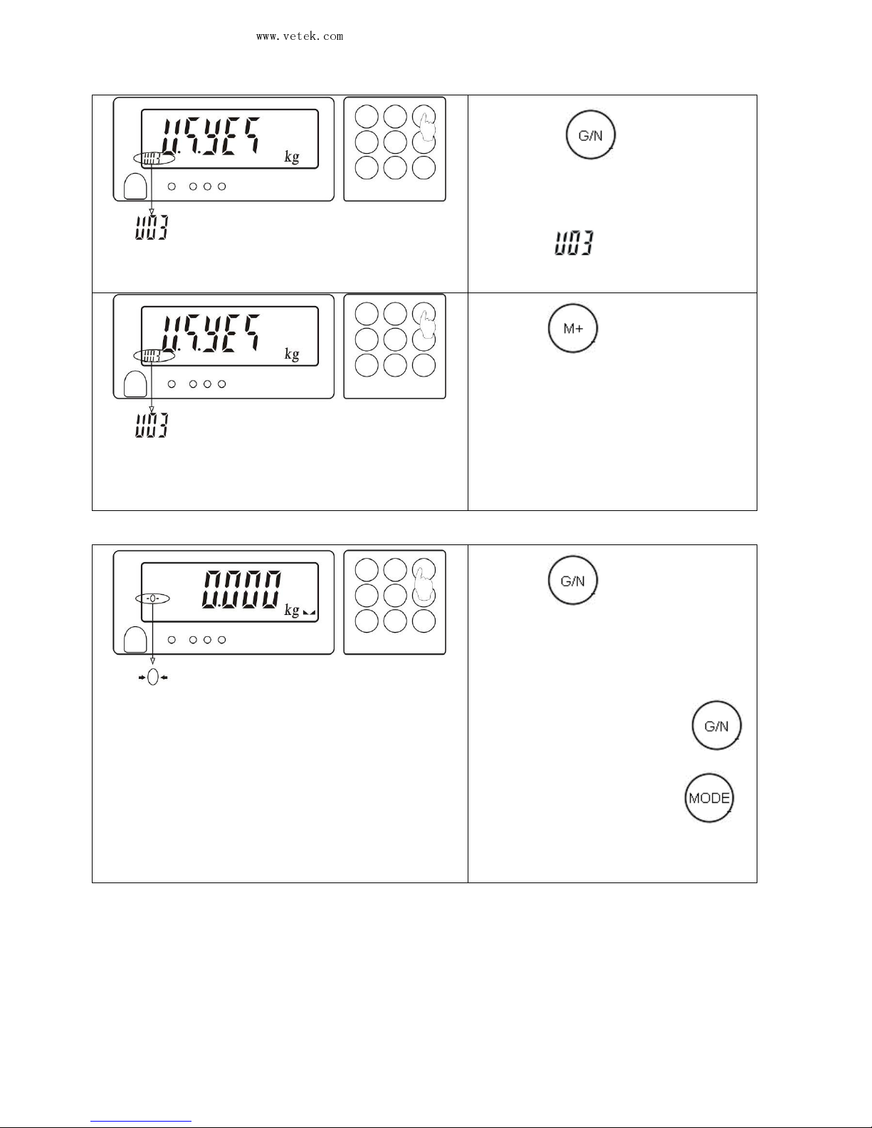
(5). Press
to store the
selection and switch to the
memo
ry unit of the scale,
with
appearing on the
lower left corner.
(6).Press
and select YES
(the unit will be the previously
used one when the scale is
turned on) or NO (the unit will
be a newly set one when the
scale is turned on).
(7).Press
to store the
selection and return to the
weighing mode.
Note: If the unit setting is accessed from the
parameter options or by Mode 2, press
to store the selection and then press
to return to the weighing mode.
Page 17
Vetek Weighing AB
www.vetek.com
JWL Service Manual
May not be reproduced in any form without written permission
PAGE
16
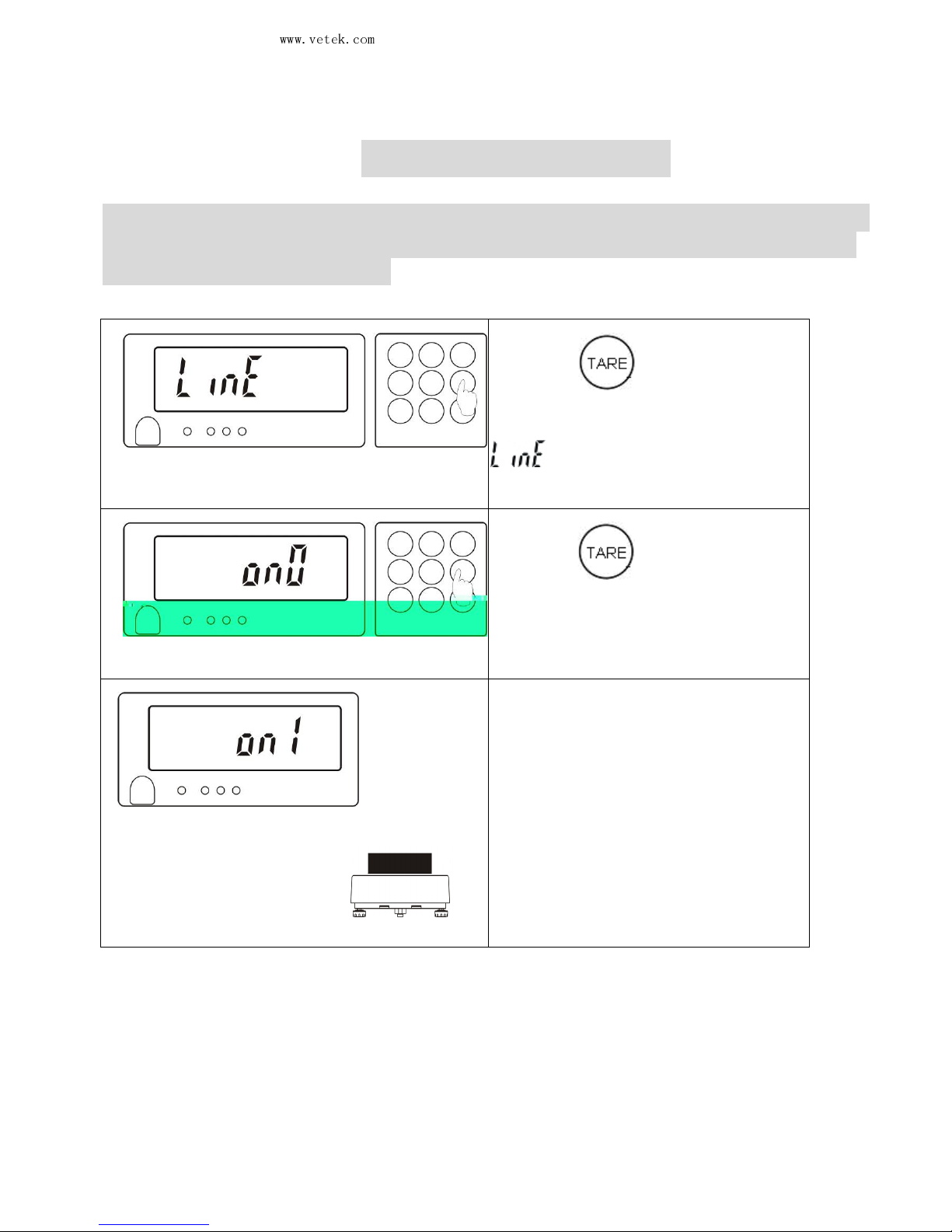
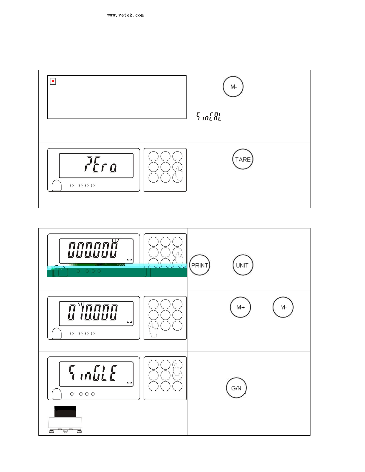
5. Linear Calibration
☆☆☆☆
If the linear calibration is made, there is no need to make the single
point calibration. If the sensor has a good linearity, make the single
point calibration directly.
(1).Press
to turn on the
unit and release the key when
appears on the LCD,
the
linear calibration mode is entered.
(2).Press
to do the zero
point calibration and wait for ON 0
to appear (No weight is put
on the
pan at this time).
(3).
Wait till ON 1 flickers on the
LCD and put on th
e weight 1/3 of
the full load. For example, 1/3 of
the weighing 30kg is 10kg.
Page 18
Vetek Weighing AB
www.vetek.com
JWL Service Manual
May not be reproduced in any form without written permission
PAGE
17
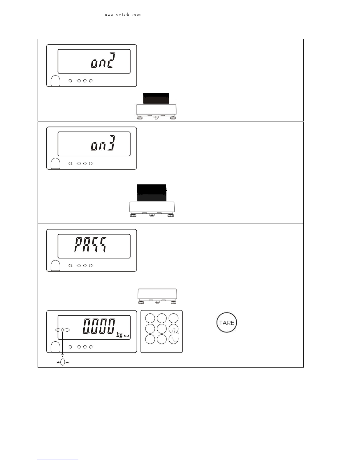
(4).
Wait till ON 2 flickers on the
LCD and put on the weight 2/3 of
the full load. For example, 2/3 of
the weighing 30kg is 20kg.
(5).
Wait till ON 3 flickers on the
LCD and put on the weight of the
full load.
(6). Wait till PASS
appears. Now,
take away the load from the pan.
(7).Press
to return to the
weighing mode.
Page 19
Vetek Weighing AB
www.vetek.com
JWL Service Manual
May not be reproduced in any form without written permission
PAGE
18
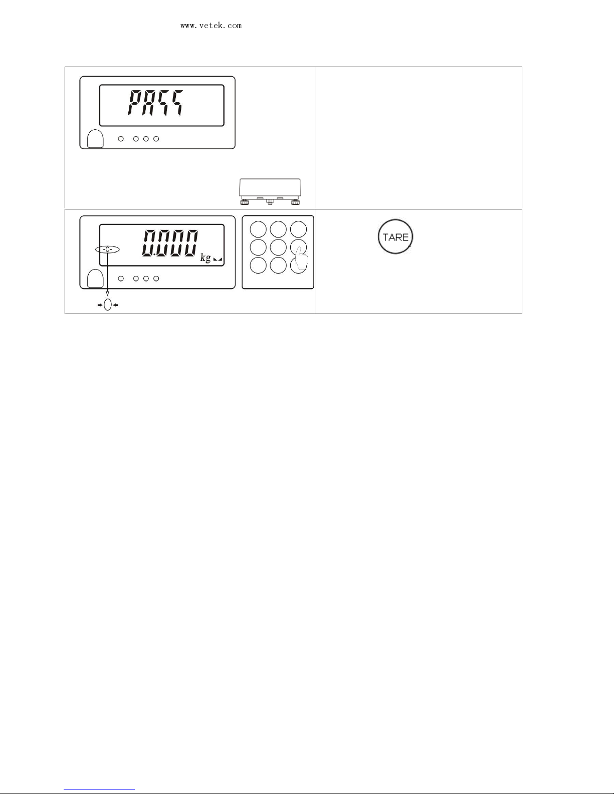
6. Single Point Calibration(底下少圖
底下少圖底下少圖
底下少圖)
(1).Press
to turn on the
unit
and release the key when
appears, the single
point calibration mode
is
entered.
(2). Press
and wait till
ZERO flickers. Now make
the
single point calibration.
(3). Wait till a
value appears and
the most right digit flickers. Press
or to move
the
flicker right or left.
(4). Press or
to
alter the value.
(5).
After the setting, put a
corresponding weight on the pan
and press
. When the LCD
flickers, make the single
point
calibration.
Page 20
Vetek Weighing AB
www.vetek.com
JWL Service Manual
May not be reproduced in any form without written permission
PAGE
19
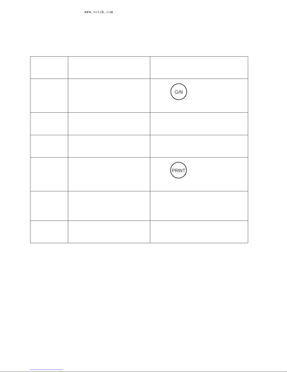
(6).
Wait till PASS appears. Now,
take away the load from the pan.
(7). Press
to return to the
weighing mode.
Page 21
Vetek Weighing AB
www.vetek.com
JWL Service Manual
May not be reproduced in any form without written permission
PAGE
20
7. Error Message List
Error
message
Possible causes Solutions
E02
no.samp
No PCS sampling
Press to make the
sampling.
E04
EE.ERR
EEPROM reading error
Re-weld the EEPROM or contact
the service department.
E05
out.ran
Overload (max weighing+9
divisions)
Take away the overload.
E07
E.Lo>H
i
The upper limit set for the
weight check is lower than
the lower limit.
Press to correct the
setting of HI/LO.
E08
CK.UNIT
The unit set for the weight
check is not the same as the
current unit.
Close the weight check or re-set
the value of HI /LO.
EU.nit
Interference between the
accumulation units
Return to the last accumulation unit
or re-do the accumulation.
Page 22
Vetek Weighing AB
www.vetek.com
JWL Service Manual
May not be reproduced in any form without written permission
PAGE
21
8. External Interface
☆☆☆☆
If an external interface is needed, please select a three-in-one board, which
combines RTC (time display) ,RS-232 and Relay (weight check) on one
circuit board. Only by selecting this board can the three functions be
realized.
☆☆☆☆ After a three-in-one board is selected, a setting should be made on the scale
for time display if necessary.
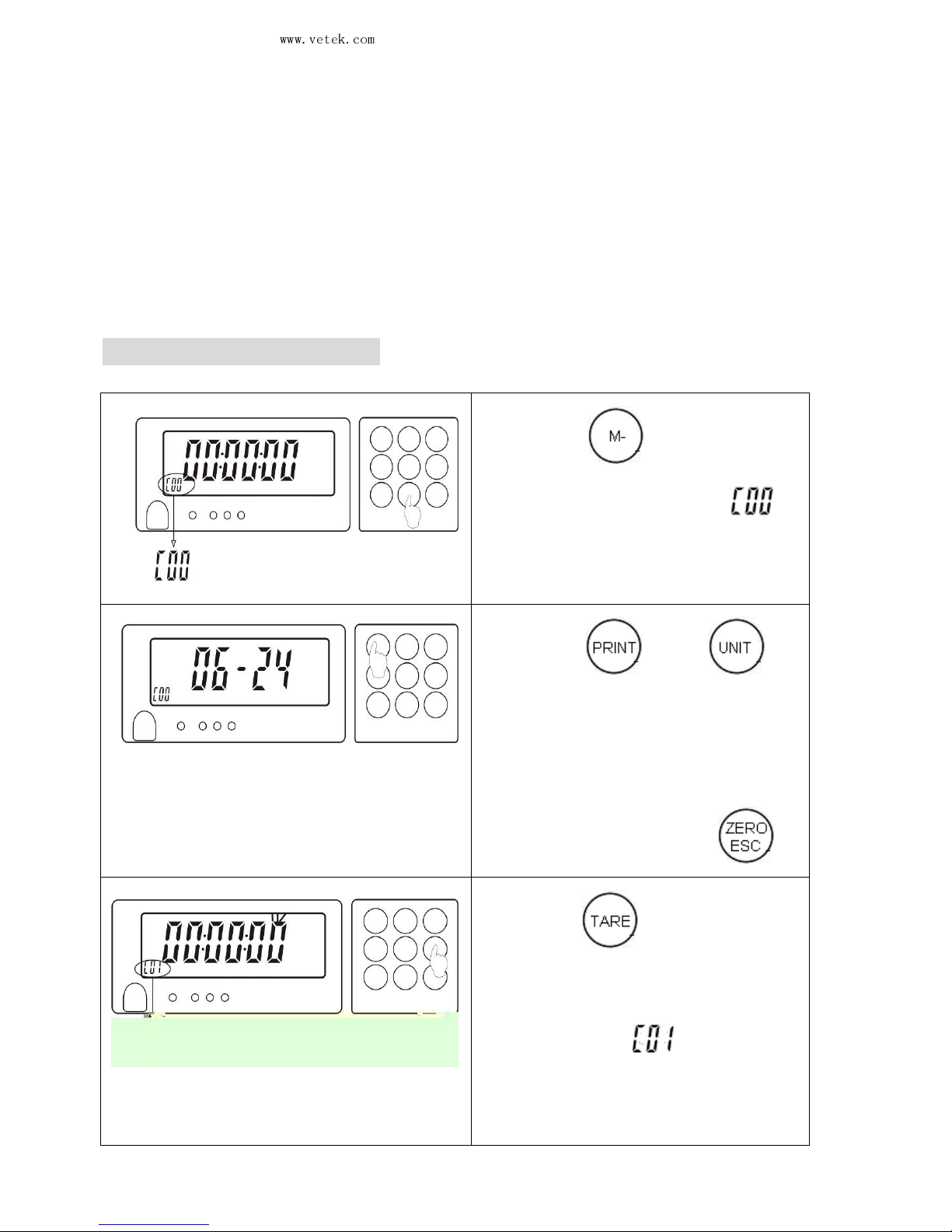
8-1. RTC function setting
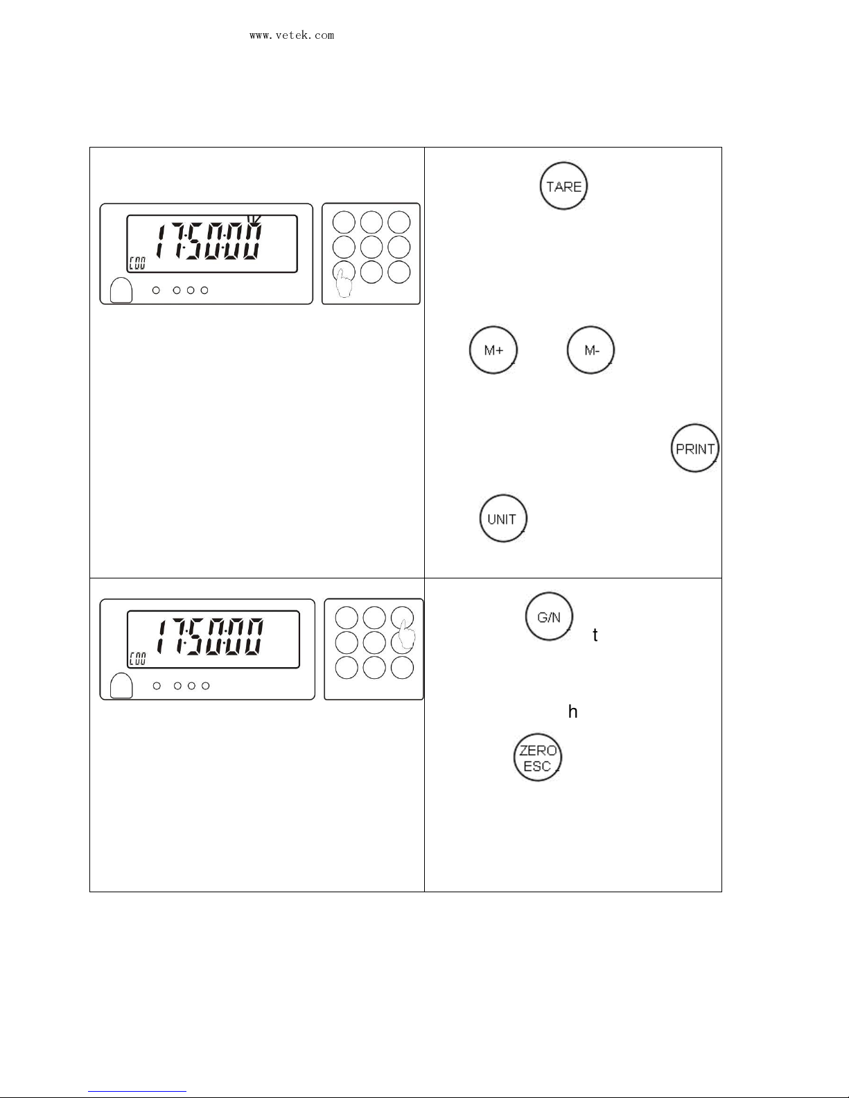
(1). Press
for 3s till time
display appears, with
on
the lower left corner.
(2). Press
or
to
switch to date-
month or year
display.
Note: For time/date setting, skip
to Step 3 and for returning to the
weighing mode, press .
(3). Press
to enter the
setting for the current time and
the last digit
for second will
flicker, with
appearing on
the lower
left corner,
representing that the first digit
from right to left can be altered.
Page 23
Vetek Weighing AB
www.vetek.com
JWL Service Manual
May not be reproduced in any form without written permission
PAGE
22
(4). Press
to move
bet
ween the digits and a
corresponding digit will flicker
when the movement is made
from right to left. Now, press
or
to increase
or decrease the value.
Note: You may press
or
to switch to the setting for
date-month or year.
(5). Press to complete
the
time setting and display the
time/date that is already
set.
To return to the weighing mode,
press
Note: This time/date setting should
be
made again when the scale is turned on
next time if a three-in-
one board is not
selected for the scale.
Page 24
Vetek Weighing AB
www.vetek.com
JWL Service Manual
May not be reproduced in any form without written permission
PAGE
23
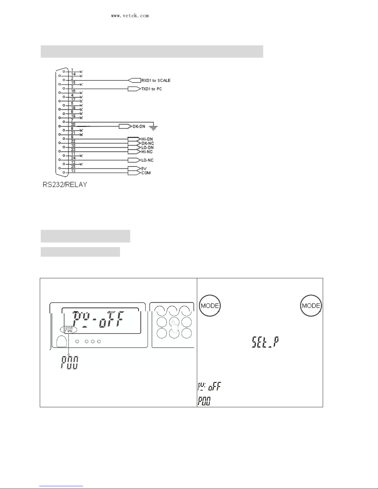
8-2 Signal output pins of three-in-one board
8-3 Single option
8-3-1 Printer output
■
Parameter setting
(1).
In weighing mode, press
for about 3s or press
and release it
when the scale is
turned on.
will first
appe
ar and then a parameter
value such as
”
” and also an auxiliary sign
.
Page 25
Vetek Weighing AB
www.vetek.com
JWL Service Manual
May not be reproduced in any form without written permission
PAGE
24
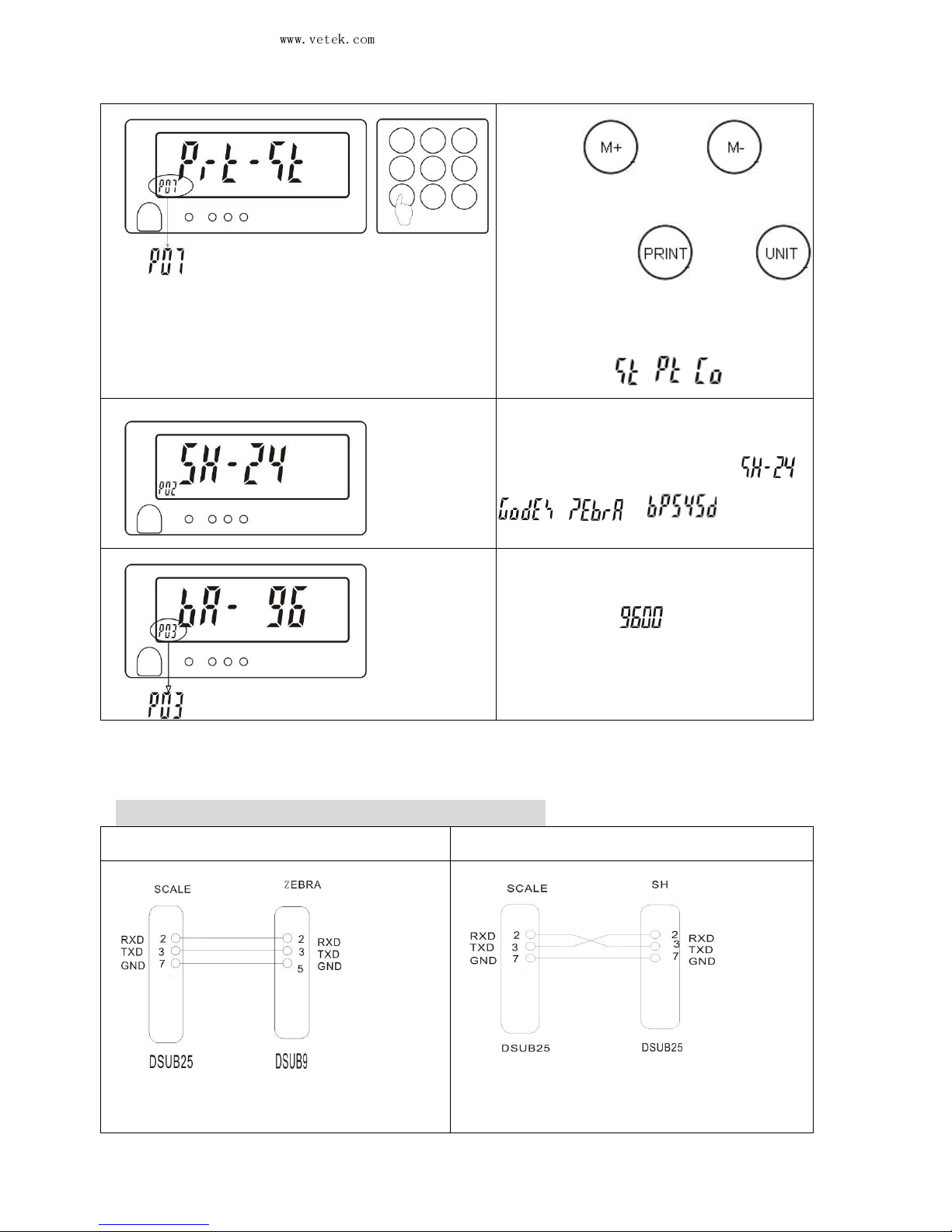
(2).Use or
to
select a parameter item such as
PO7. Press or
to select the parameter value
,
with the printing modes
including / / .
(3). Follow Step (2)
to select the
parameter item P02, with the
printing modes including
/
/
/ .
(4). Follow
Step (2) to select the
parameter item P03
, selecting the
Baud rate of .
■
Wire connecting the scale and the printer
Wire connecting ZEBRA Wire connecting SH-24
That is the commonly used 9male
~25male RS232 connecting wire.
That is the commonly used 25male~25 male
RS232 connecting wire. You have to
exchange by yourself the pin 2 with the pin 3
Page 26
Vetek Weighing AB
www.vetek.com
JWL Service Manual
May not be reproduced in any form without written permission
PAGE
25
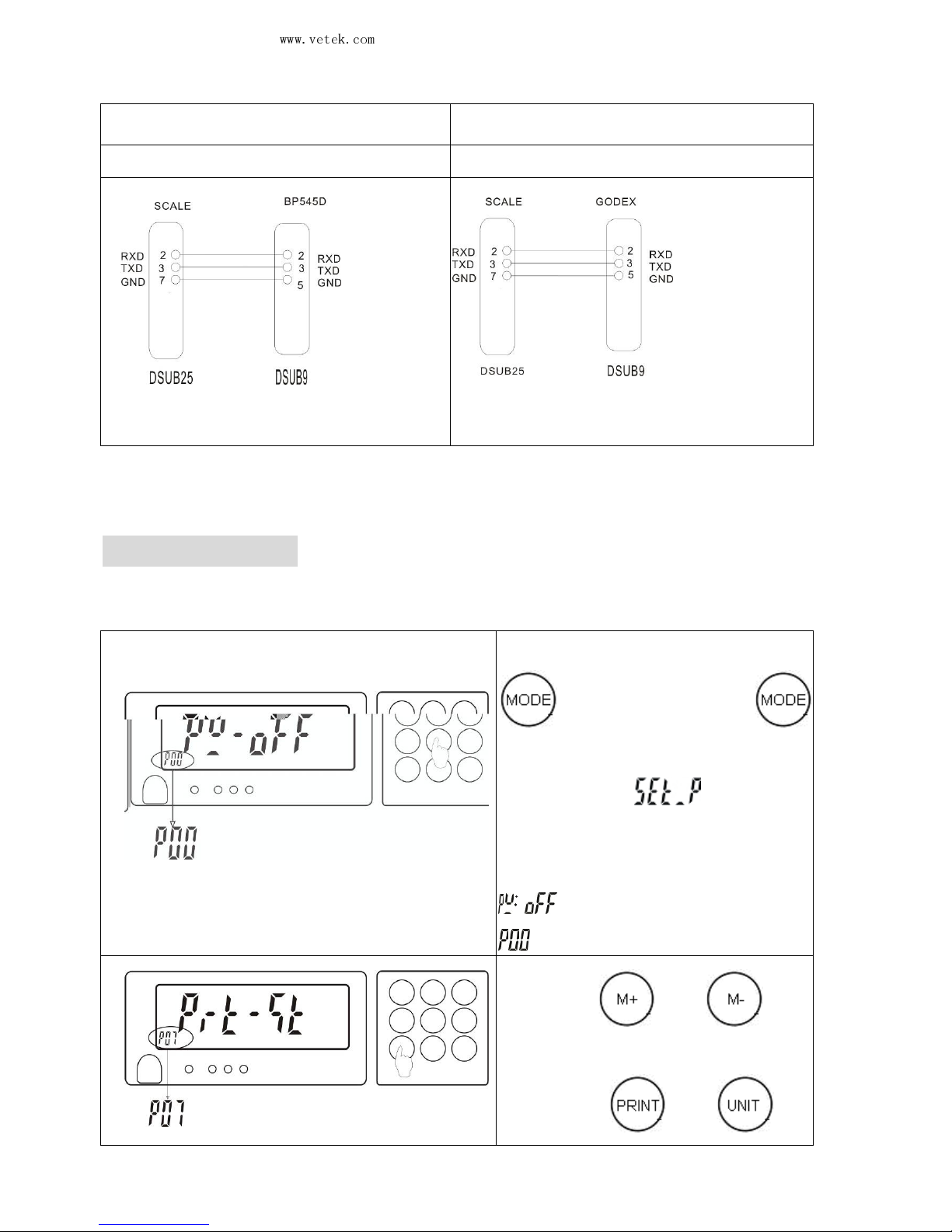
at one end of the wire bought.
Wire connecting BP545D Wire connecting GODEX
That is the commonly used 9male ~25male
RS232 connecting wire.
That is the commonly used 9male ~25male
RS232 connecting wire.
8-3-2 PC output
■
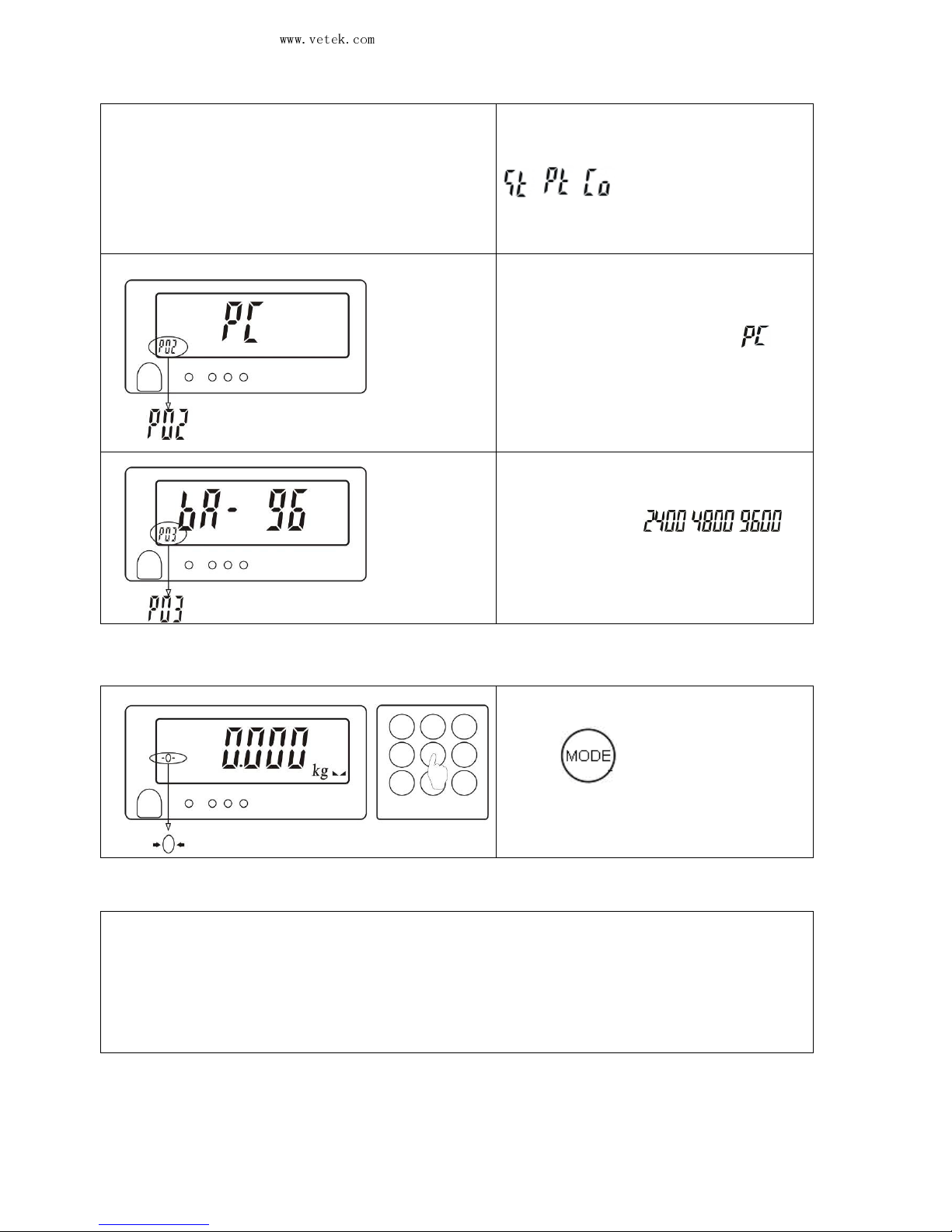
Parameter setting
(1).
In weighing mode, press
for about 3s or press
and release it
when the scale is
turned on.
will first
appear and then a parameter
value such as
”
” and also an auxiliary sign
.
(2). Use or
to
select a parameter item such as
PO7. Press or
to
Page 27
Vetek Weighing AB
www.vetek.com
JWL Service Manual
May not be reproduced in any form without written permission
PAGE
26
select the parameter value, with
the
printing modes including
/ / .
(3). Follow
Step (2) to select the
parameter item P02, with the
printing mode selected as .
(4). Follow
Step (2) to select the
parameter item P03, selecting the
Baud rate from / / .
(5).
When the setting is completed,
press
to store the setting
and return to the weighing mode.
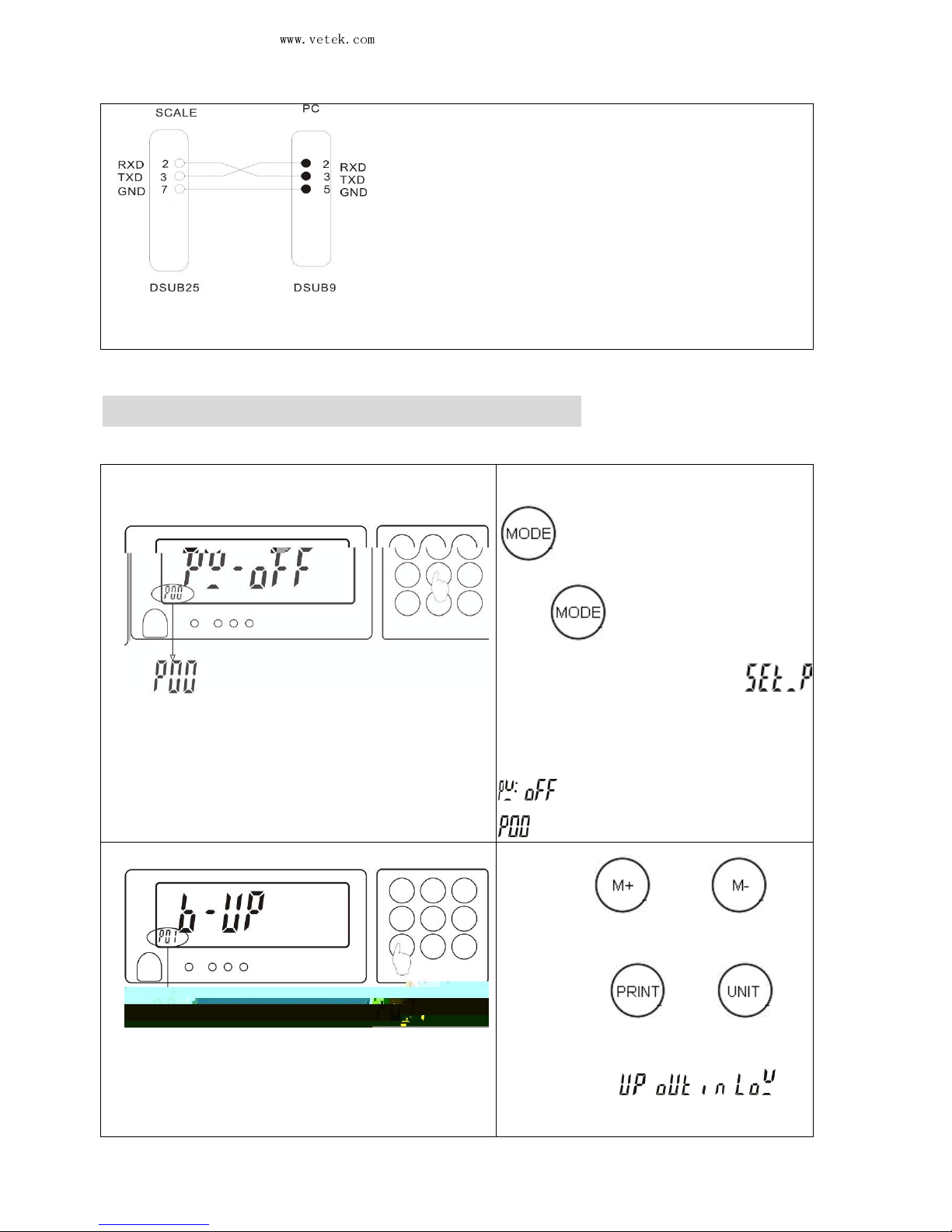
■Wire connecting the scale and the PC
How to use a PC to receive the weighing information?
(1) Use the connecting wire as shown in the following figure to connect the
scale and the PC.
(2) Set the printing mode as continuous.
(3) Now, the scale will output the data to the PC.
(Of course, you must have a receiving program at the PC end.)
Page 28
Vetek Weighing AB
www.vetek.com
JWL Service Manual
May not be reproduced in any form without written permission
PAGE
27
That is the commonly used 9 female ~25male RS232 connecting wire. You have to
exchange by yourself the pin 2 with the pin 3 at one end of the wire bought.
Note: The hollow dots represent that the connectors are male and the black dots, female.
8-3-3 Warning light connection for use
■ Parameter setting of beeps for weight check:
(1).
In weighing mode, press
for about 3s or
press
and release it when
the scale is turned on.
will first appear and then a
parameter value such as
” ” and also an auxiliary s
ign
.
(2). Use or
to
select a parameter item such as
PO1. Press or
to
select the parameter value, with
four modes / / /
for
selection.
Page 29
Vetek Weighing AB
www.vetek.com
JWL Service Manual
May not be reproduced in any form without written permission
PAGE
28
(3).
When the setting is
completed, press
to store
the setting and return to the
weighing mode.
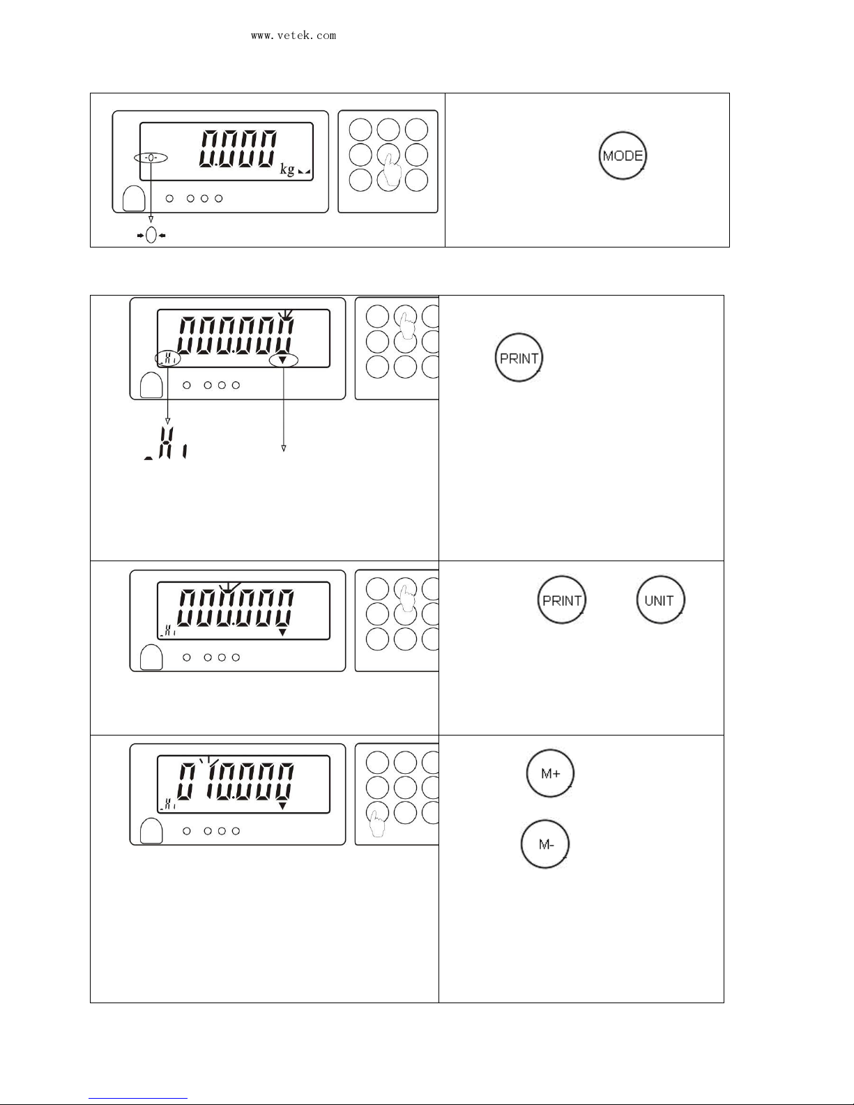
■ Setting for the upper and lower limits of weight check
(1).
In weighing mode,
press for 3s and
the
screen enters the state for digit
entry. Enter the value at the
first
zero on the right
which flickers on
the LCD.
(2). Press or
to
move
the flickering cursor left or
right to the digit where you want
to enter a value.
(3). Press
to increase the
value or to decrease the
value and select the weight value
you want to enter.
(4). Repeat Steps (2) and (3)
to
complete the setting for t
he upper
limit. For example, 10.000kg.
Triangle indicator for the upper
or lower limit
Page 30
Vetek Weighing AB
www.vetek.com
JWL Service Manual
May not be reproduced in any form without written permission
PAGE
29
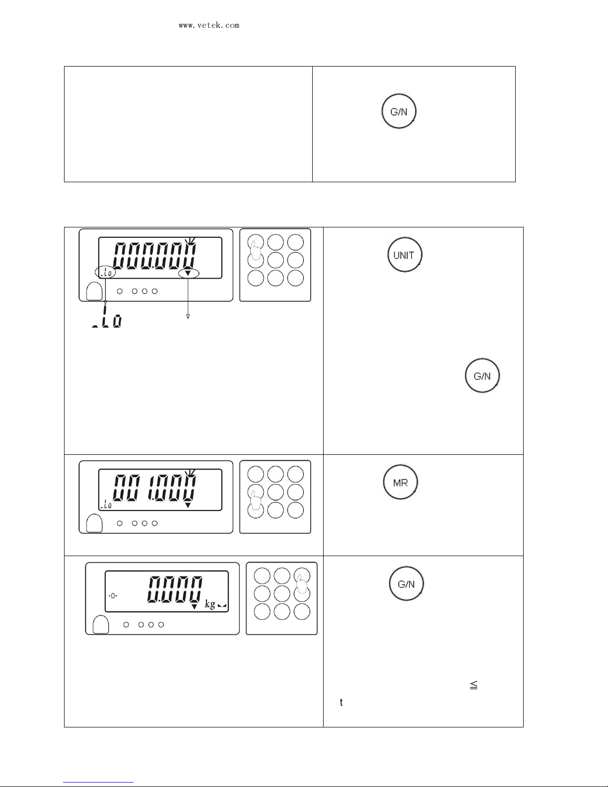
Note: After completing
Step (4), you may
directly press
to store the upper
limit value or directly skip to Step (6).
(5). Press for 3s and
the
screen enters the state for digit
entry. Repeat Steps (2), (3)
and
(4)
to complete the setting for the
lower limit. For example, 1.000kg.
Note: you may directly press
to
store the lower limit value or directly skip to
Step (6).
(6). Press
to start or cancel
the check.
(7). Press
to return to the
weighing mode. If the triangle
indicator for
the upper or lower
limit appears, it is in the check
mode.
Note: Only when the lower limit ≦
the upper
limit value can the check mode be started.
It is the same for other unit setting.
Triangle indicator for the upper
or lower limit
Page 31
Vetek Weighing AB
www.vetek.com
JWL Service Manual
May not be reproduced in any form without written permission
PAGE
30
Note:
- 1.
When the material weight exceeds 10.000kg, there will be an
acoustic warning and the red light will be on.
2. When the material weight is smaller than or equal to 10.000kg
and
greater than or equal to 1.000kg, the green warning light will be on.
3. When the material weight is smaller than 1.000kg and greater than
or equal to 20 divisions, the orange warning light will be on.
- 1.
When the material weight exceeds 10.000kg, there will be an
acoustic warning and the red light will be on.
2. When the material weight is smaller than or equal to 10.000kg
and
greater than or equal to 1.000kg, the green warning light will be on.
3. When the material weight is smaller than 1.000kg and greater than
or equal to 20 divisions, there will be an acoustic warning and
the
orange warning light will be on.
- 1.
When the material weight exceeds 10.000kg, the red light will be on.
2. When the material weight is smaller than or equal to 10.000kg
and greater
than or equal to 1.000kg, there will be an acoustic warning and
the green
warning light will be on.
3. When the material weight is smaller than 1.000kg and greater than
or
equal to 20 divisions, the orange warning light will be on.
-1. When the material weight exceeds 10.000kg, the red light will be on.
2. When the material weight is smaller than or equal to 10.000kg
and greater
than or equal to 1.000kg, the green warning light will be on.
3.
When the material weight is smaller than 1.000kg and greater than
or
equal to 20 divisions, there will be an acoustic warning and
the orange
warning light will be on.
■
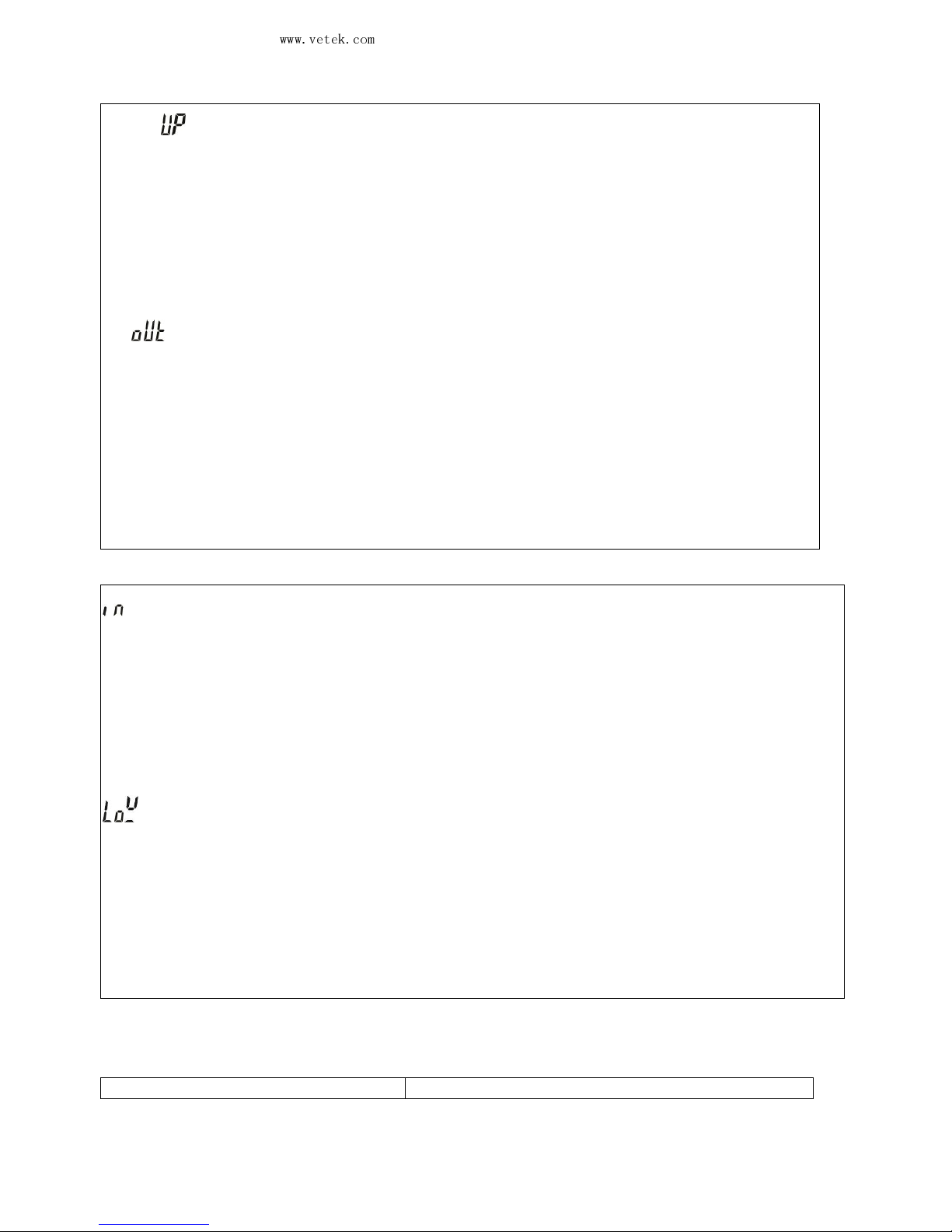
Pins for connecting the warning lights
Pins for connecting the warning lights
Picture
Page 32
Vetek Weighing AB
www.vetek.com
JWL Service Manual
May not be reproduced in any form without written permission
PAGE
31
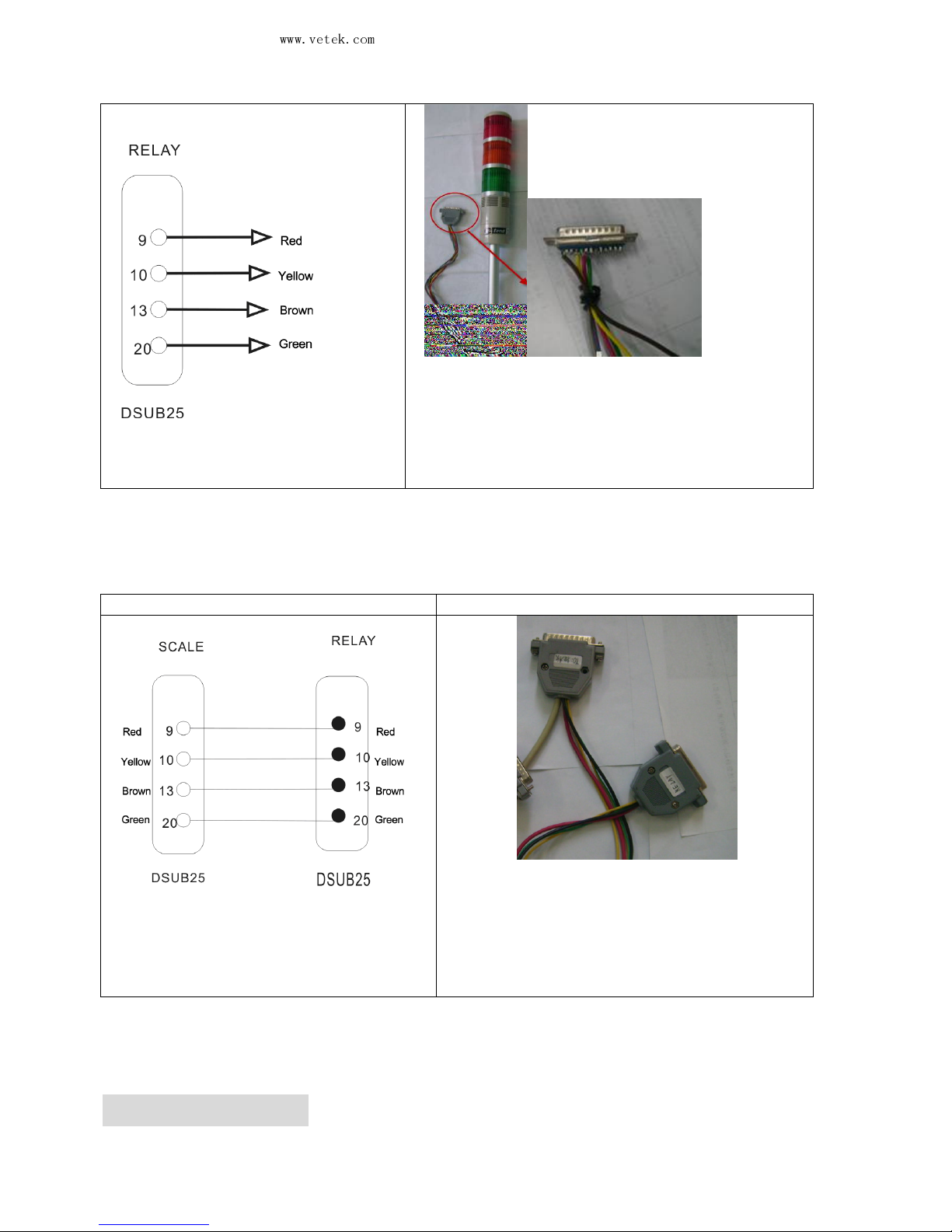
The pins for the warning lights are connected
to the 25-male socket.
■ Wire connecting the scale and the warning light
Wire connecting the warning lights Picture
That is the commonly used 25male and 25
female RS232 connecting wire.
Note: The hollow dots represent the male
connectors and the black dots, female
connectors.
8-4. Two options
Page 33
Vetek Weighing AB
www.vetek.com
JWL Service Manual
May not be reproduced in any form without written permission
PAGE
32
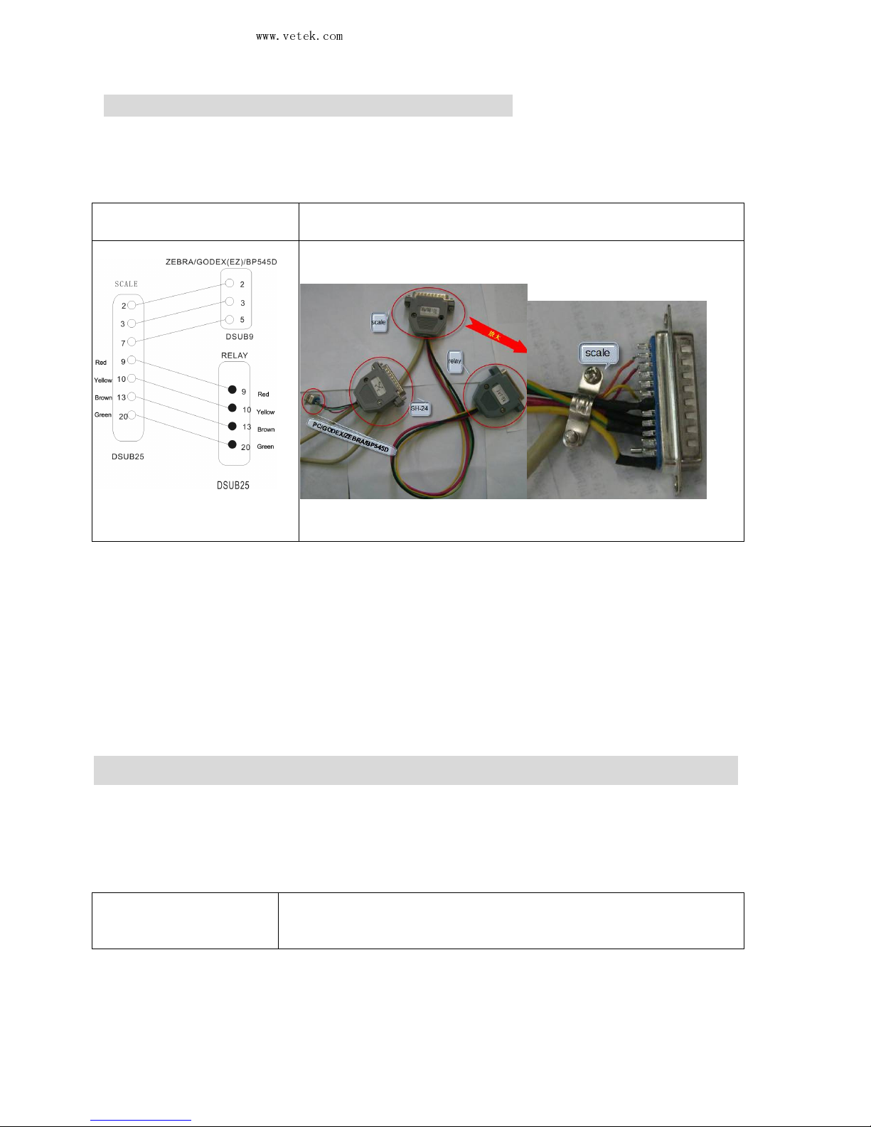
8-4-1 Joint use of PC output and warning light
8.4.1.1 The parameter setting is the same as specified in 8-3-2, 8-3-3
8.4.1.2 Wire connecting the scale to the PC and the warning light
Wire connecting the PC
and the warning light
Picture
Note: The hollow dots
represent
the male connectors and the
black dots, female connectors.
8-4-2 Joint use of SH-24 printer output and warning light
8-4-2-1 The parameter setting is the same as specified in 8-3-1 and 8-3-3
8-4-2-2 Wire connecting the scale to the SH-24 printer and the warning light
Wire connecting the
SH-24 printer and the
warning light
Picture
Page 34
Vetek Weighing AB
www.vetek.com
JWL Service Manual
May not be reproduced in any form without written permission
PAGE
33
Note: The hollow dots
represent the male
connectors and the black
dots, female connectors.
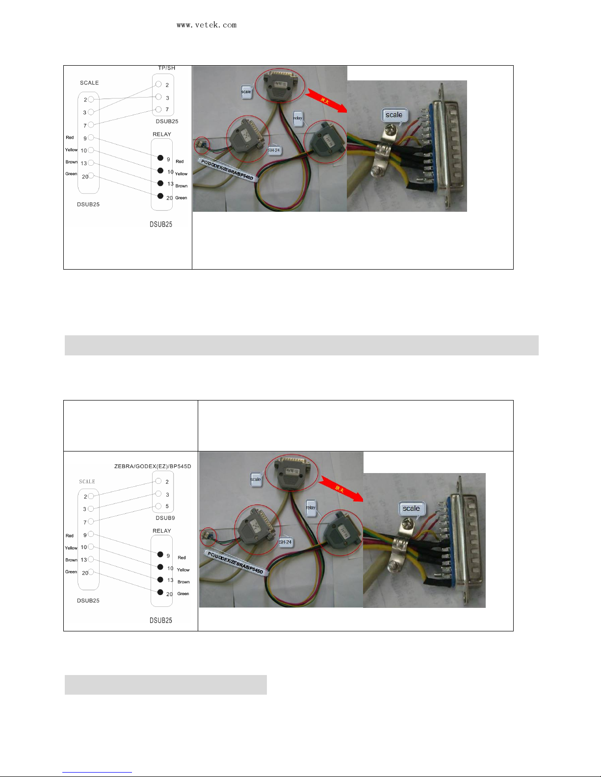
8-4-3 Joint use of ZEBRA or other printers and warning light
8-4-3-1 The parameter setting is the same as specified in 8-3-1 and 8-3-3
8-4-3-2 Wire connecting the scale to a ZEBRA or other printers and the warning
light
Wire connecting the
ZEBRA/GODEX(EZ)/BP
545D printer and the
warning light
Picture
8-5. RS-232 output format
Baud Rate: 2400, 4800, 9600
Data Bit: 8
Page 35
Vetek Weighing AB
www.vetek.com
JWL Service Manual
May not be reproduced in any form without written permission
PAGE
34
Parity: N (None)
Stop Bit: 1
Code: ASCII
Bit Format:
LSB MSB
0 1 2 3 4 5 6 7 8
Start Bit
Parity Stop Bit
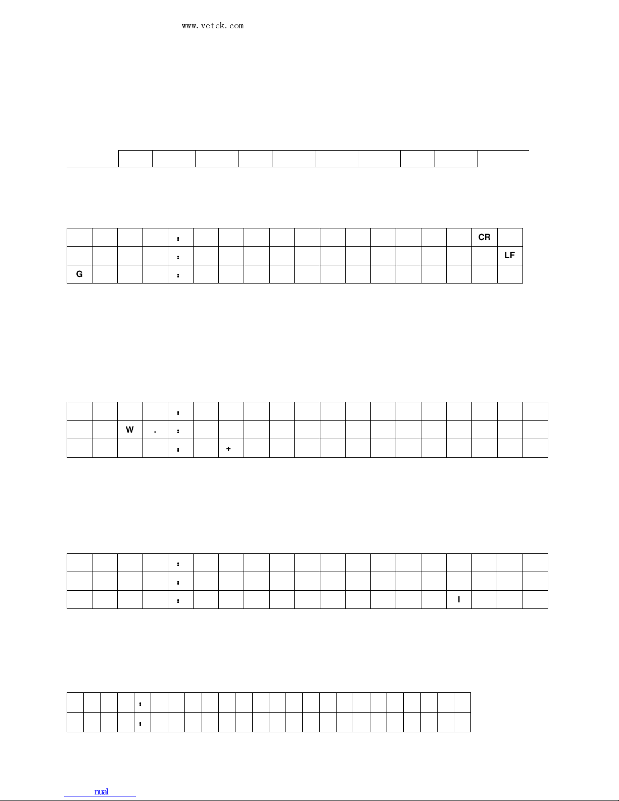
Data Format:
g
N . W .
::::
+/- g CR LF
T . W .
::::
+/- g CR LF
G . W .
::::
+/- g CR LF
Weight
Example
N.W.: + 1000.0 g
T.W.: + 500.4 g
G.W.: + 1500.4 g
kg
N . W .
::::
+/-
k g CR LF
T . W .
::::
+/-
k g CR LF
G . W .
::::
+/-
k g CR LF
Weight
Example
N.W.: + 1.0000 kg
T.W.: + 0.4998 kg
G.W.: + 1.4998 kg
lb
N . W .
::::
+/-
l b CR LF
T . W .
::::
+/-
l b CR LF
G . W .
::::
+/-
l b CR LF
Weight
Example
N.W.: + 2.2050 lb
T.W.: + 1.1020 lb
G.W.: + 3.3070 lb
Jin (Taiwan)
N . W .
::::
+/-
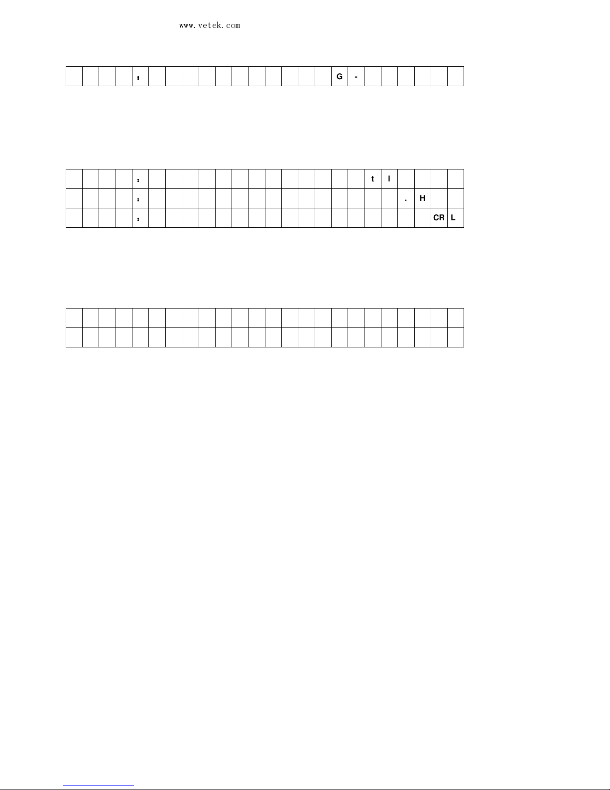
G - t l . T CR LF
T . W .
::::
+/- G - t l . T CR LF
Page 36
Vetek Weighing AB
www.vetek.com
JWL Service Manual
May not be reproduced in any form without written permission
PAGE
35
G . W .
::::
+/- G - t l . T CR LF
Weight
Example
N.W.: + 1.94.8 G-tl.T
T.W.: + 0.13.2 G-tl.T
G.W.: + 2.08.0 G-tl.T
Jin (Hong Kong)
N . W .
::::
+/- G - t l . H CR LF
T . W .
::::
+/- G - t l . H CR LF
G . W .
::::
+/- G - t l . H CR LF
Weight
Example
N.W.: + 1.94.4 G-tl.H
T.W.: + 0.13.2 G-tl.H
G.W.: + 2.07.6 G-tl.H
PCS
t o t a l
:
CR LF
p c s CR LF
Example
Total:
50pcs
9. Others
Page 37
Vetek Weighing AB
www.vetek.com
JWL Service Manual
May not be reproduced in any form without written permission
PAGE
36
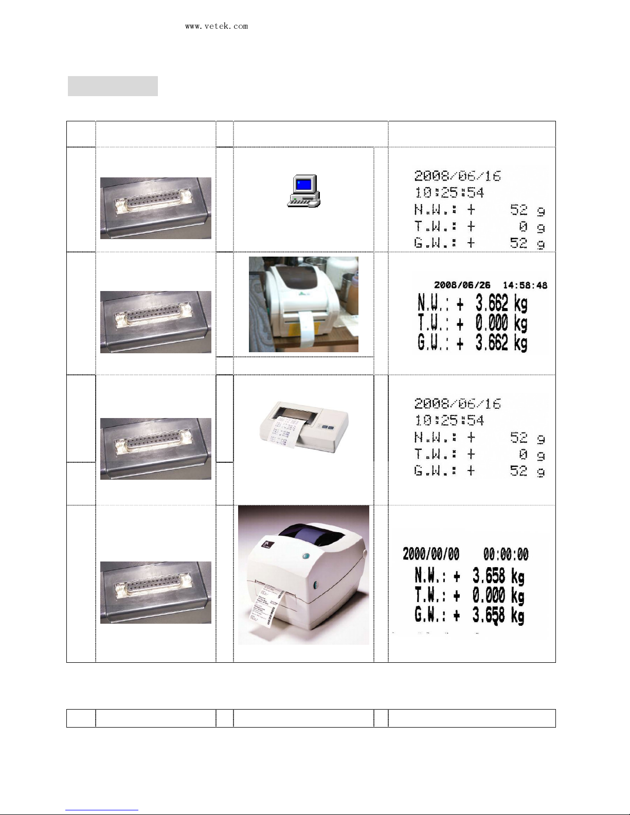
9-1 Options
Example of use of single option
Option External device Output format
AP0
RS232+RTC+Relay
++++
PC
→→→→
AP1
RS232+RTC+Relay
++++
→→→→
BP-545D
AP2
RS232+RTC+Relay
++++
→→→→
SH-24
AP3
RS232+RTC+Relay
++++
→→→→
ZEBRA
Page 38
Vetek Weighing AB
www.vetek.com
JWL Service Manual
May not be reproduced in any form without written permission
PAGE
37
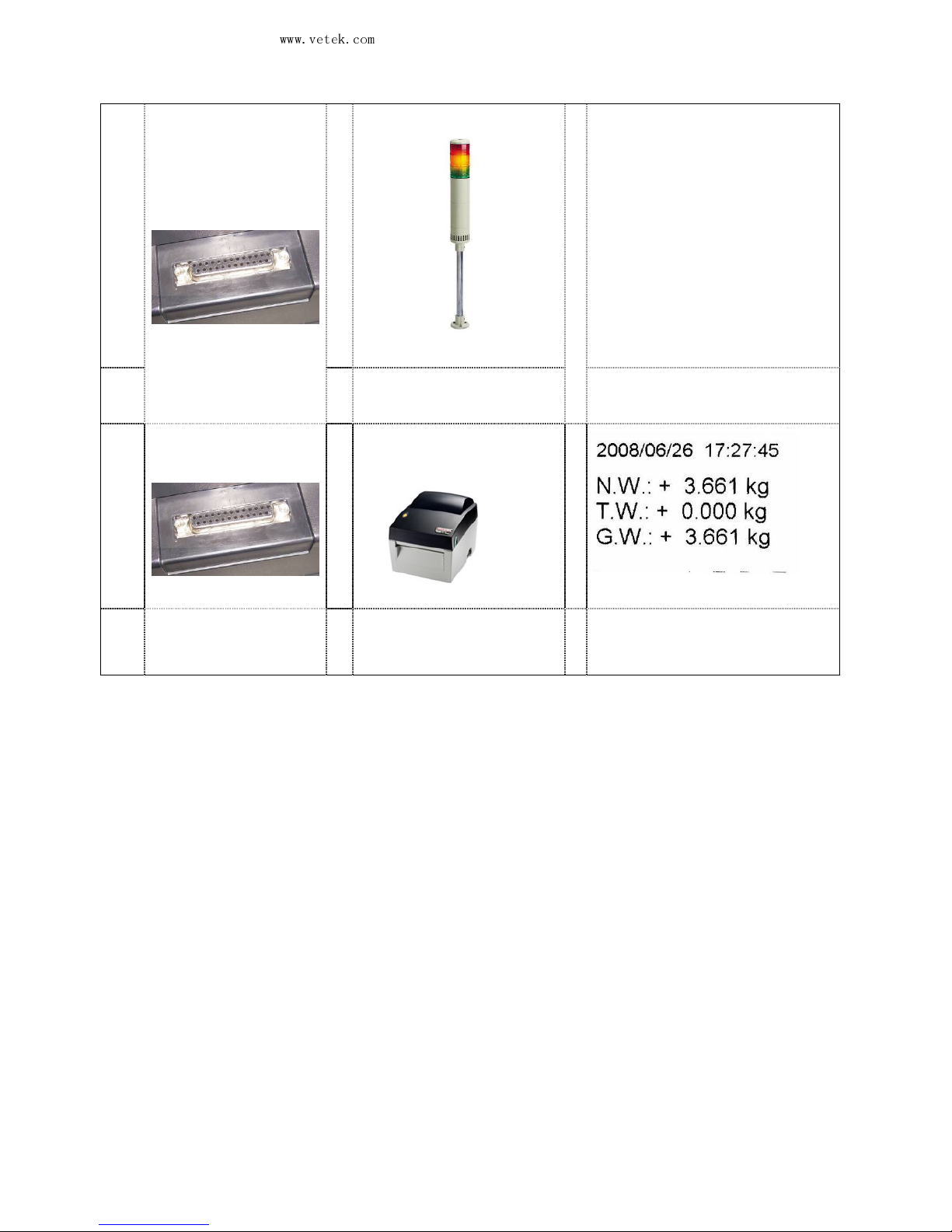
AP4
RS232+RTC+Relay
++++
→→→→
Applicable to the quality control
of the factory product quantity
or weight and that of the total
production line.
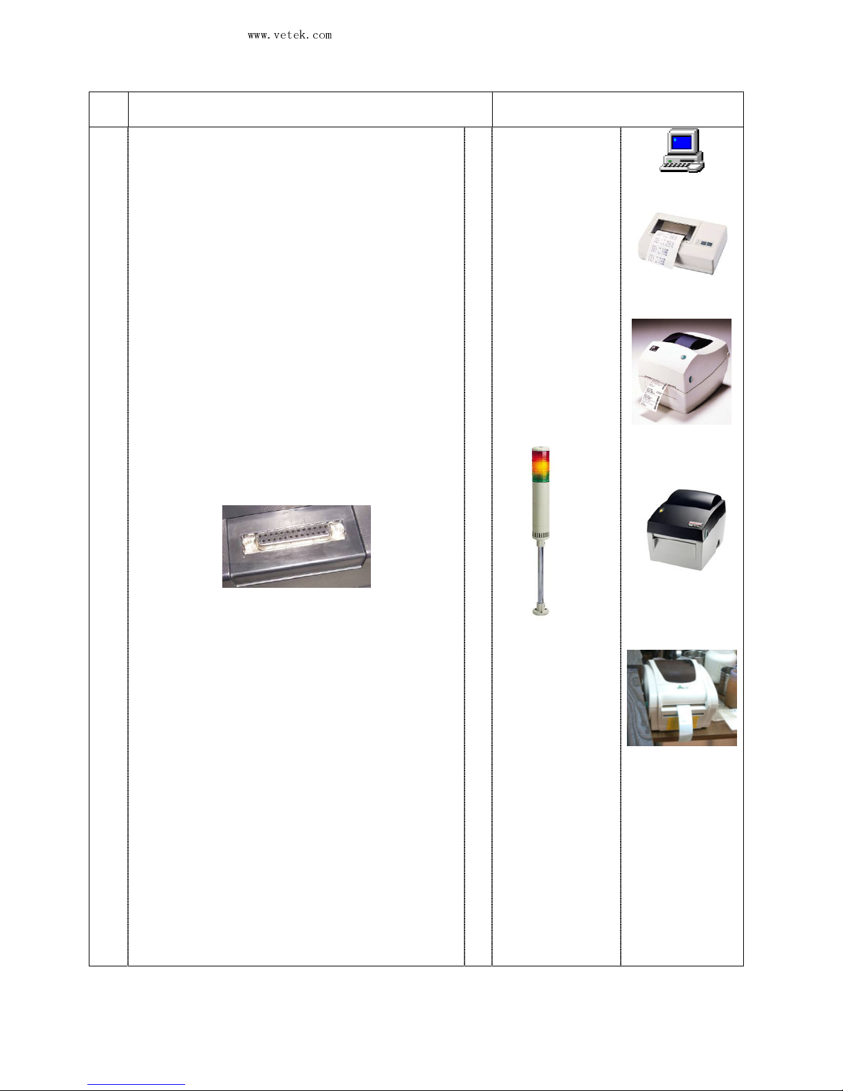
LED Light Tower
AP5
RS232+RTC+Relay
++++
GODEX(EZ)
Examples of use of options
Page 39
Vetek Weighing AB
www.vetek.com
JWL Service Manual
May not be reproduced in any form without written permission
PAGE
38
Option
External device
AP1
→→→→
+
LED Light Tower
or
or
or
or
PC
/
SH-24
/
ZEBRA
/
EZ
/
BP-545D
10 Circuit Diagram
Page 40
Vetek Weighing AB
www.vetek.com
JWL Service Manual
May not be reproduced in any form without written permission
PAGE
39
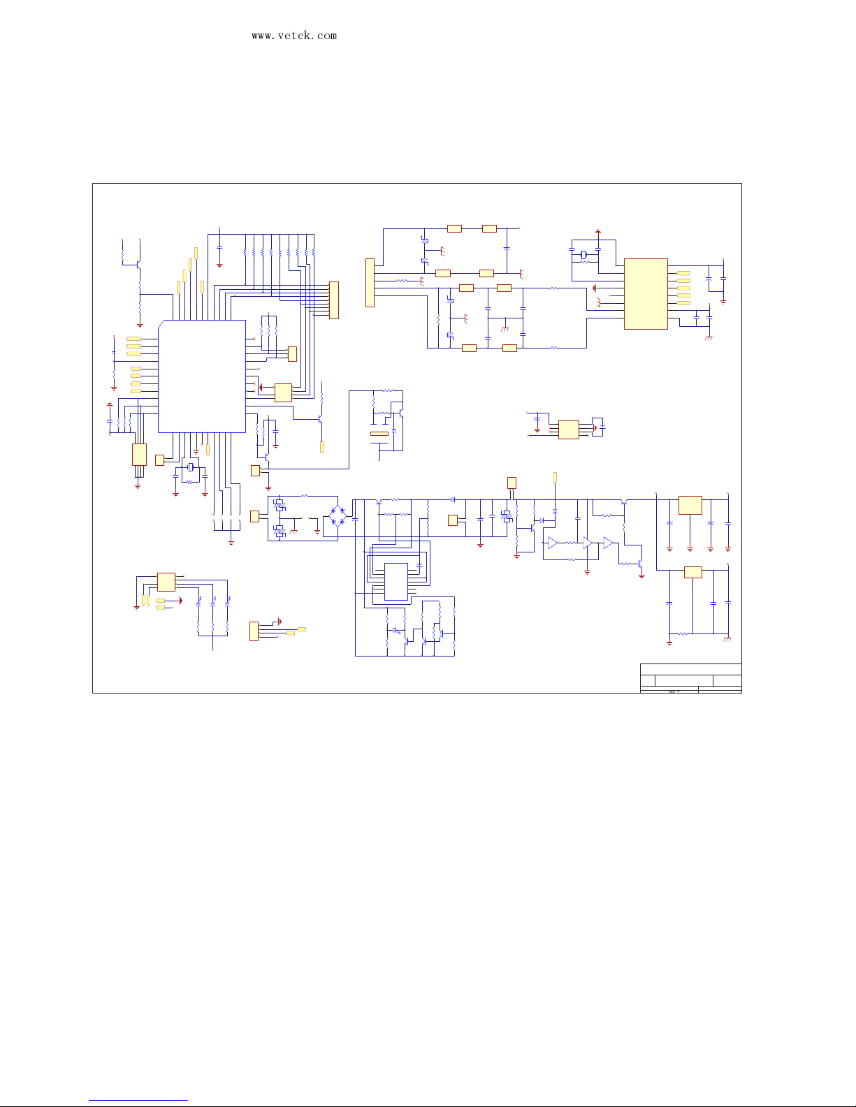
10-1. CPU, peripheral circuit and other circuits
Title
Number RevisionSize
A2
Date: 1 -Sep-2008 Sheet of
File:
料料
资
E:\jadever\LX \L-SCALE.ddb Drawn By:
R24
10k,C
MCB6
R53
20k,C
C10
1u,T
Y2
4.9152MHz
C9
1u,T
CP11
0.1u,G
FB1
1
2
CN9
ON/OFF
CP10
0.1u,G
1
2
CN2
EH-Adpator
E+
1
G
3
E-
2
S+
4
S-
5
CN1
LOAD-CELL
R3
100,A,T
12
J1
D3
1N4148
D4
1N4148
AVS5
AVS6
R22
330k,C
R18
1k,C
R17
4.7k,C
NC
1
CURLIM
2
CURSEN
3
IN-
4
IN+
5
Nref
6
V-7NC
8
Vz
9
Vout
10
Vc
11
V+
12
COMP
13
NC
14
U1
LM723
R8
4.7k,C
R56
10k,A
R9
1k,C
R7
2/1w,C
R55
1.5k,A
R21
330k,C
R23
2.2k,C
1
2
CN3
Battery
1
3 2
Q6
2SB857
CP14
0.1u,G
R15
4.7k,C
C19
470u,EL
V ss
3
Out1Vdd
2
U4
LM2931
3
1 2
Q7
2SC1815
R20
1M,C
MCB7
213
Q1
D313
MCB8
C16
470u,EL
IN1OUT
3
G N D
2
U3
LM2930
CP13
0.1u,G
D2
1N4004
2
3
1
Q4
A733
C13
470P
+
C11
470 u /2 5 v, E L
R16
100k,C
CP5
0.1u,G
AVS1
MCB1
CP7
0.1u,G
AVS2
CP6
0.1u,G
AVS3
CP8
0.1u,G
AVS4
R19
10k,C
Q11
2SC1815
MCB2
MCB3 MCB4
DGND
1
MCLK
2
XTAL
3
DGND
4
REFP
5
REFN
6
AIN0
7
AIN1
8
AGND
9
ACDD
10
CS
11
SDI
12
SDO
13
SCLK
14
DRDY
15
DVDD
16
U6
CS1180
R5 4
33 0k ,C
R52
560R,C
D8
1N414 8
MCB5
AVS7
R4
1M,C
C8
20p
C7
20p
FB2
+
C12
470u,EL
R13
1k,C
2
3
1
Q3
2SC1815
R14
1K,C
R12
1k,C
2
3
1
Q2
2SC1815
D1
LED-RL
1
2
3
4
CN4
RS232
C18
220u,EL
FUSE
0
G
1
M
2
F
3
BZ
R1
1M,A,T
R2
100,A,T
P3
TXD
RXD
AD SDO
AD SCLK
AD CS
AD SDI
AD RST
BAT +5VD
+5VA
+5VD
+5VA
+5VA
+5VD
JWL V1.1
1
2
3
4
U5
CP12
0.1u,G
-5VD
NC
1
CAP+
2
GND
3
CAP-4VOUT
5
LV
6
DSC
7
V+
8
U11
7660
C35
220u,EL
C36
470u,EL
+5VD
-5VD
R2 6
10 0 k ,C
3
12
Q8
A733
R25
22k,C
1
2
CN7
EH-BU ZZER
CP16
0.1u,G
1 2
TP3
1 2
TP2
1 2
TP1
1
2
3
CN10
RTC
1 2
CAL
R39
10K,C
R40
10K,C
R45
10K,C
Y1
11.059MHz
R41
10K,C
P4. 21P1. 02P1. 13P1. 24P1. 35P1. 4
6
P1.5
7
P1.6
8
P1.7
9
RST
10
P4.3
12
P3.0 / (RXD)
11
P3.1 / (TXD)
13
P3.2 / (not INT0)
14
P3.3 / (not INT1)
15
P3.4/(T0)
16
P3.5/(T1)
17
P3. 6 / (n o t W R )18P3. 7 / (n o t R D )19XT A L20XT A L21GN D22P4. 023P2. 024P2. 125P2. 226P2. 327P2. 4
28
P2.5
29
P2.6
30
P2.7
31
PSEN
32
ALE / not PROG
33
P4.1
34
not EA / VPP
35
P0.7
36
P0.6
37
P0.5
38
P0.4
39
P0. 340P0. 241P0. 142P0. 0
43
V CC
44
U7
AT89C51/52
1
2
3
4
5
6
7
8
9
CN8
JWEL
R38
10K,C
R42
10K,C
R28
1M,C
C20
20p
R43
10K,C
R44
10K,C
C21
20p
CP17
0.1u,G
SC L K
P3.2
A D RS T
TXD
RXD
A D SD I
AD SD O
LCD-CS
+5VD
LCD-DATA
LCD-WR
+5VD
A D CS
A
14
B
13
G
15
Y0
12
Y1
11
Y2
10
Y3
9
R34
10k,C
3
12
Q10
A733
R35
10k,C
R36
10k,C
BAT+5VD
C22
10u,EL
R32
4.7 k .C
+5VD
P3
A 01A 12A 23G N D
4
SD A
5
SC L
6
WP
7
VC C
8
U8
HT24C02A
R30
4.7 k .C
R31
4 .7k .C
R29
4.7 k .C
CP18
0.1u,G
+5VD
1
2
CW
CN6
P2. 0
+5VD
R46
10K,C
U9B
3
1 2
Q9
2SC1815
R27
330Ω,C
+5VD
LE D
KO U T 1
KO U T 2
KO U T 3
KO U T 4
KIN1
KIN2
KIN3
KIN4
KIN5
R62
4.7 k .C
R63
4.7 k .C
R61
4.7 k .C
+5VD
C1
10u,T
R65
10k,C
R66
47K,C
R64
47k,C
2
3
1
Q5
2SC1815
U15C
U15B
U15A
C15
220u,EL
1 2
3 4 5 6
C2
104P
+5VA
D5
OK
A
2
B
3
G
1
Y0
4
Y1
5
Y2
6
Y3
7
U9A
74LS139
R50
1k,C
D6
HI
R51
1k,C
D7
LO
R49
1k,C
P3. 2
P2. 0
U9.16
U9.8
+5VD
+5VD
Page 41
Vetek Weighing AB
www.vetek.com
JWL Service Manual
May not be reproduced in any form without written permission
PAGE
40
10-2
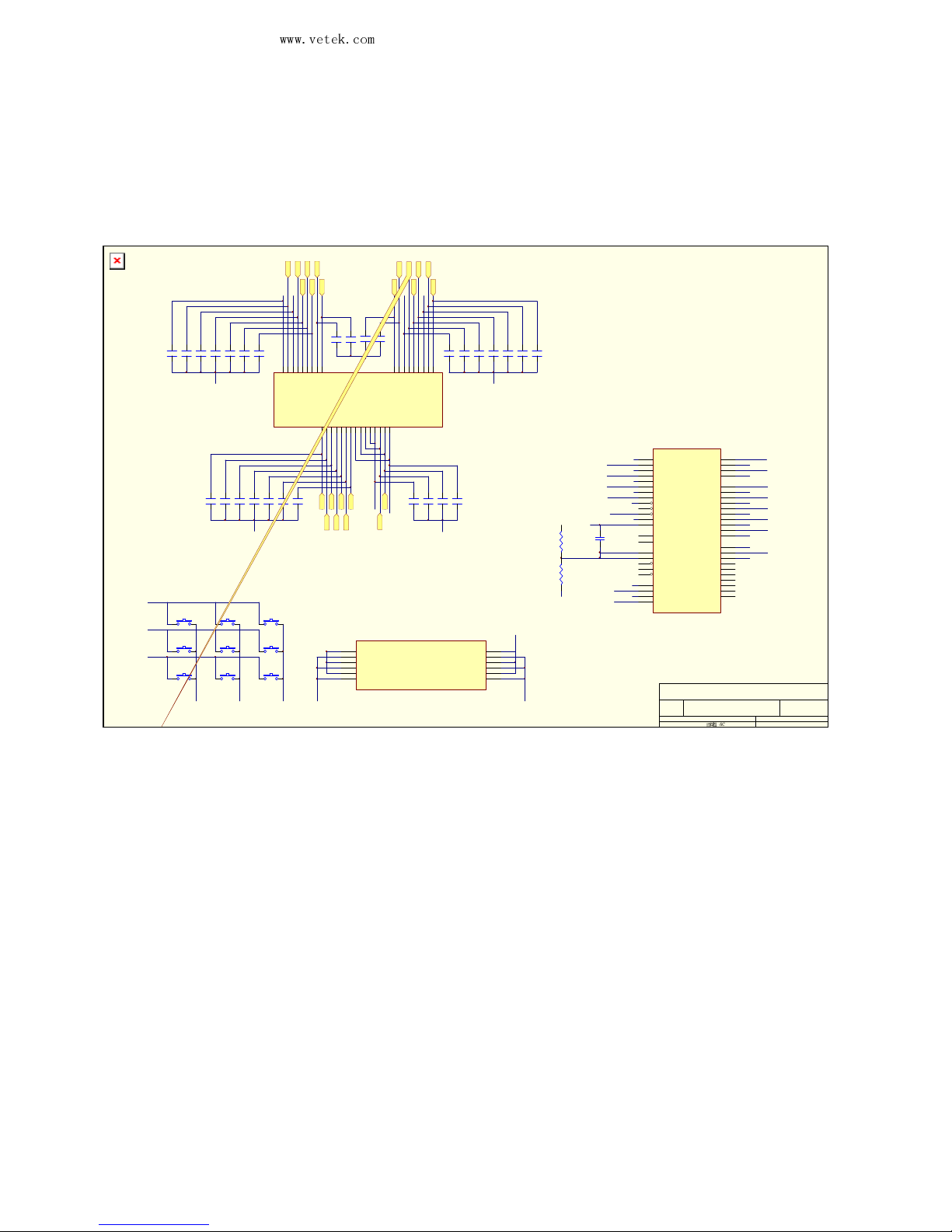
. LCD circuit
Title
Number RevisionSize
A3
Date: 1-Sep-2008 Sheet of
File:
料料
资
E:\jadever\LX \L-SCALE.ddb Drawn By:
KIN4
KOU T3
KOU T1
KOU T2
KIN5
KIN3
+
1
-
2
+
3
-
4
+
5
-
6
+
1
-
2
+
3
-
4
+
5
-
6
LED4
1 2
SW7
1 2
SW8
1 2
SW9
1 2
SW2
1 2
SW4
1 2
SW6
1 2
SW1
1 2
SW5
1 2
SW3
C61
33p
C63
33p
C64
33p
C66
33p
C65
33p
C60
33p
C62
33p
S33S44S55S66S77C48C39C210C111C112C4
15
S816S9
17
S1018S1119S1220S1321S1422S1523S16
24
S1725S1826S1927S2028S2129S2230S2331S24
32
S22S1
1
C213C3
14
S25
33
LCD4
C54
33p
C69
33p
C70
33p
C50
33p
C53
33p
C67
33p
C68
33p
C57
33p
C56
33p
C52
33p
C51
33p
C42
33p
C43
33p
C44
33p
C55
33p
C46
33p
C47
33p
C49
33p
C48
33p
C45
33p
R58
4700Ω,C
R57
220Ω,C
CP19
0.1u,G
SEG7
1
SEG6
2
SEG5
3
SEG4
4
SEG3
5
SEG2
6
SEG1
7
SEG0
8
CS
9
RD
10
WR
11
DATA
12
Vss
13
OSC0
14
OSC1
15
VLCD
16
VDD
17
IRQ
18
BZ
19
BZ
20
COM0
21
COM1
22
COM2
23
COM3
24
SEG31
25
SEG30
26
SEG29
27
SEG28
28
SEG27
29
SEG26
30
SEG25
31
SEG24
32
SEG23
33
SEG22
34
SEG21
35
SEG20
36
SEG19
37
SEG18
38
SEG17
39
SEG16
40
SEG15
41
SEG14
42
SEG13
43
SEG12
44
SEG11
45
SEG10
46
SEG9
47
SEG8
48
U14
HT1621B
C58
33p
C59
33p
CS19
CS18
CS6
CS1
CS5
CS12
CS3
CS2
CS4
CS9
CS8
CS7
CC2
CS16
CS17
CS22
CS21
CS11
CS20
CC3
CS24
CS15
10 - 3. Applicable mainboard version and software version
Mainboard version: JWL-V1.1 (50-0900-0000)
Software version: JWL1.01
Revision date: Nov. 28, 2008
 Loading...