

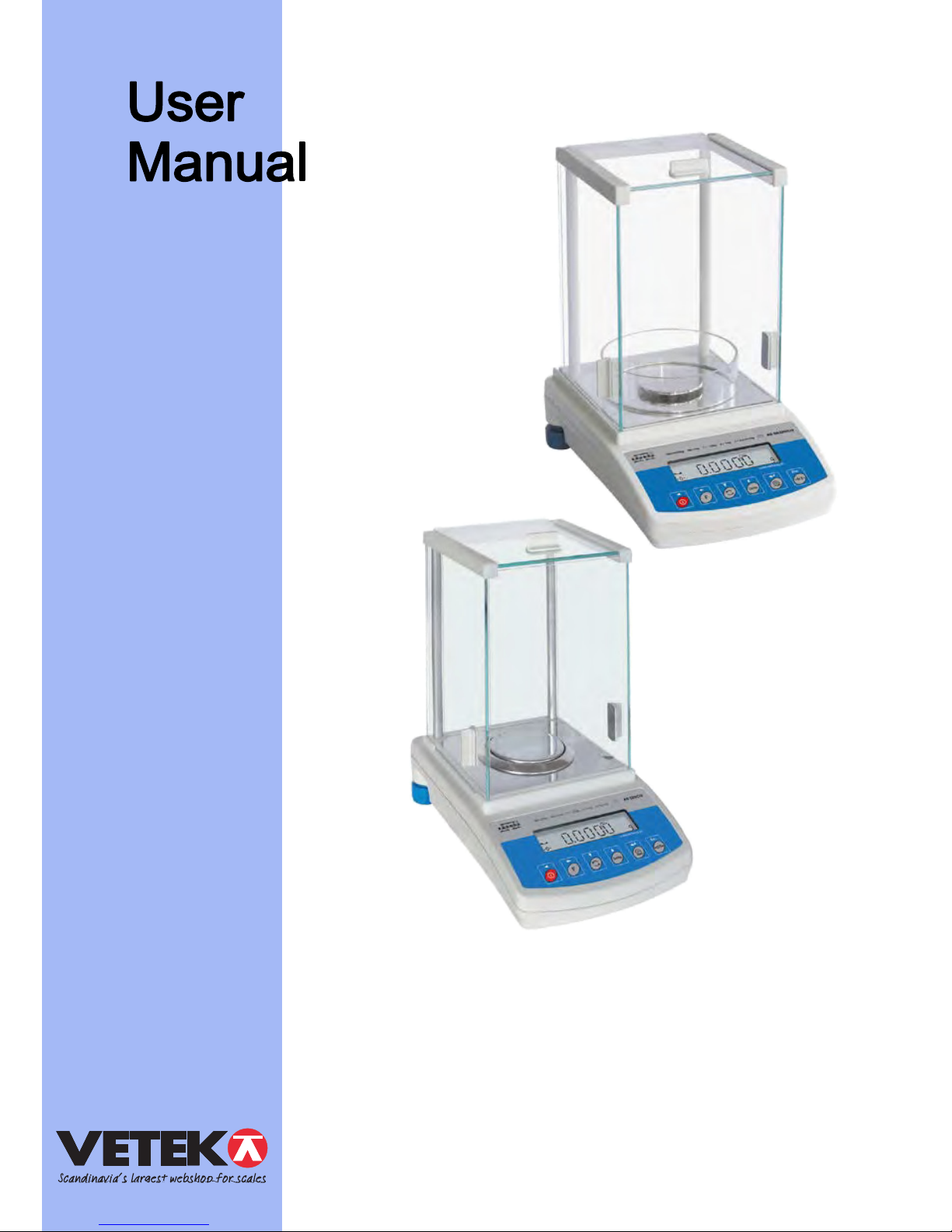
Vetek AS 310/C/2, AS 60/220/C/2, AS 220/C/2, APS 120/C/2/CT, APS 220/C/2/CT User Manual
...Page 1
User manual no.
LMI-16-09/05/12/A
PRECISION
BALANCE
AS SERIES
PRECISION
BALANCE
AS/CT SERIES
M A NUF A C T URE R
O F E L E C T R O N I C W E I G H I N G I N S T R U M E N T S
RADWAG 26 – 600 Radom, Bracka 28, POLAND
phone +48 48 38 48 800, fax. +48 48 385 00 10
e-mail: export@radwag.com
www.radwag.com
Box 79, S-76040 Väddö, Sweden, Tel +46176-208920, [email protected], www.vetek.com
Page 2

- 2 -
MAY 2012
Page 3

- 3 -
TABLE OF CONTENTS
1. TECHNICAL DATA ................................................................................ 5
2. BASIC INFORMATION .......................................................................... 7
2.1. Intended use ............................................................................................... 7
2.2. Inappropriate use........................................................................................ 7
2.3. Warranty ..................................................................................................... 7
2.4. Monitoring metrological parameters of the instrument ................................ 8
2.5. Data included in this user manual............................................................... 8
2.6. Staff training ............................................................................................... 8
3. TRANSPORT AND STORAGE .............................................................. 8
3.1. Delivery check ............................................................................................ 8
3.2. Packaging ................................................................................................... 8
4. UNPACKING, ASSEMBLING AND STARTUP ...................................... 9
4.1. Assembling, and place of use ..................................................................... 9
4.2. Unpacking ................................................................................................ 10
4.3. Leveling .................................................................................................... 11
4.4. Standard equipment ................................................................................. 12
4.5. Cleaning ................................................................................................... 12
4.6. Plugging to mains ..................................................................................... 12
4.7. Connecting peripheral devices ................................................................. 12
5. BASIC FUNCTIONS ............................................................................. 12
6. KEYBOARD ......................................................................................... 14
7. START-UP ........................................................................................... 15
8. USER MENU ........................................................................................ 16
8.1. Moving through user menu ....................................................................... 16
8.2. Return to weighing mode .......................................................................... 18
9. WEIGHING ........................................................................................... 20
9.1. Selection of basic measuring unit ............................................................. 21
9.2. Temporary measuring unit ........................................................................ 22
9.3. Setting accessibility of balance working modes ........................................ 23
9.3.1. Selection of working modes available for a user ............................. 23
9.3.2. Means of selecting one of available working modes ....................... 25
10. BALANCE MAIN PARAMETERS ......................................................... 27
10.1. Setting level of filtering ............................................................................. 27
10.2. Value release ........................................................................................... 28
10.3. Autozero function...................................................................................... 29
10.4. Blanking of last digit on the display........................................................... 30
10.5. Weighing mode RAPID ............................................................................. 31
11. OTHER PARAMETERS ....................................................................... 32
11.1. Backlight of weighing result (display backlight) ........................................ 32
11.2. “Beep” sound – reaction on pressing a function key ................................. 33
11.3. Printout of all balance parameters through RS 232 port ........................... 33
12. BALANCE ADJUSTMENT ................................................................... 34
12.1. Internal adjustment ................................................................................... 35
12.2. Settings of menu: Adjustment ................................................................... 37
12.3. Adjustment test ......................................................................................... 40
12.4. Manual adjustment ................................................................................... 41
Page 4

- 4 -
12.4.1. Internal adjustment ..................................................................... 41
12.4.2. External adjustment .................................................................... 42
12.5. Adjustment report printout ........................................................................ 43
13. DETERMINING CONTENT OF A PRINTOUT FOR GLP
PROCEDURES .............................................................................. 44
14. BALANCE WORKING MODES ............................................................ 47
14.1. Parts counting of the same mass ............................................................. 48
14.2. Checkweighing (HiLo) with reference to set standard .............................. 53
14.3. Percent setup ........................................................................................... 56
14.3.1. Reference mass determined by weighing ................................... 56
14.3.2. Reference mass set in balance memory by a user ..................... 57
14.4. Working mode FILL .................................................................................. 59
14.5. Density determination of solids and liquids ............................................... 60
14.5.1. Density determination of solids ................................................... 61
14.5.2. Density determination of liquid .................................................... 61
14.6. Pipettes calibration ................................................................................... 62
14.6.1. Data input ................................................................................... 62
14.6.2. First measuring series ................................................................ 63
14.6.3. Second measuring series ........................................................... 64
14.6.4. Third measuring series ............................................................... 65
15. RS 232 FUNCTIONS ........................................................................... 67
15.1. Baud rate .................................................................................................. 67
15.2. Continuous transmission .......................................................................... 68
15.2.1. Continuous transmission in basic measuring unit ....................... 68
15.2.2. Continuous transmission in current measuring unit .................... 69
15.3. Setting operation mode for RS 232 interface ............................................ 70
15.4. Determination of data type sent via RS 232 output .................................. 71
15.5. Minimum mass required for activating automatic printout ......................... 72
16. COOPERATION WITH A PRINTER OR A COMPUTER ..................... 73
16.1. Cross-section through connecting conductors .......................................... 74
16.2. Printing date with specified date and time ................................................ 75
16.3. Cooperation with statistic printer KAFKA SQS ......................................... 75
16.4. Format of data sending ............................................................................. 75
16.4.1. Format of data sent on pressing of PRINT key ........................... 76
16.4.2. Format of data sending as response to commands generated
from a computer ....................................................................................... 76
17. UNDER HOOK WEIGHING ................................................................. 78
18. LIST OF COMMANDS: COMPUTER – BALANCE .............................. 79
19. ERROR MESSAGES ........................................................................... 80
20. ADDITIONAL EQUIPMENT ................................................................. 81
20.1. Anti-vibration table .................................................................................... 81
20.2. Rack for under hook weighing .................................................................. 81
20.3. Density determination kit (for solids and liquids) ...................................... 81
20.4. Additional display...................................................................................... 81
20.5. Computer software ................................................................................... 82
Page 5
- 5 -
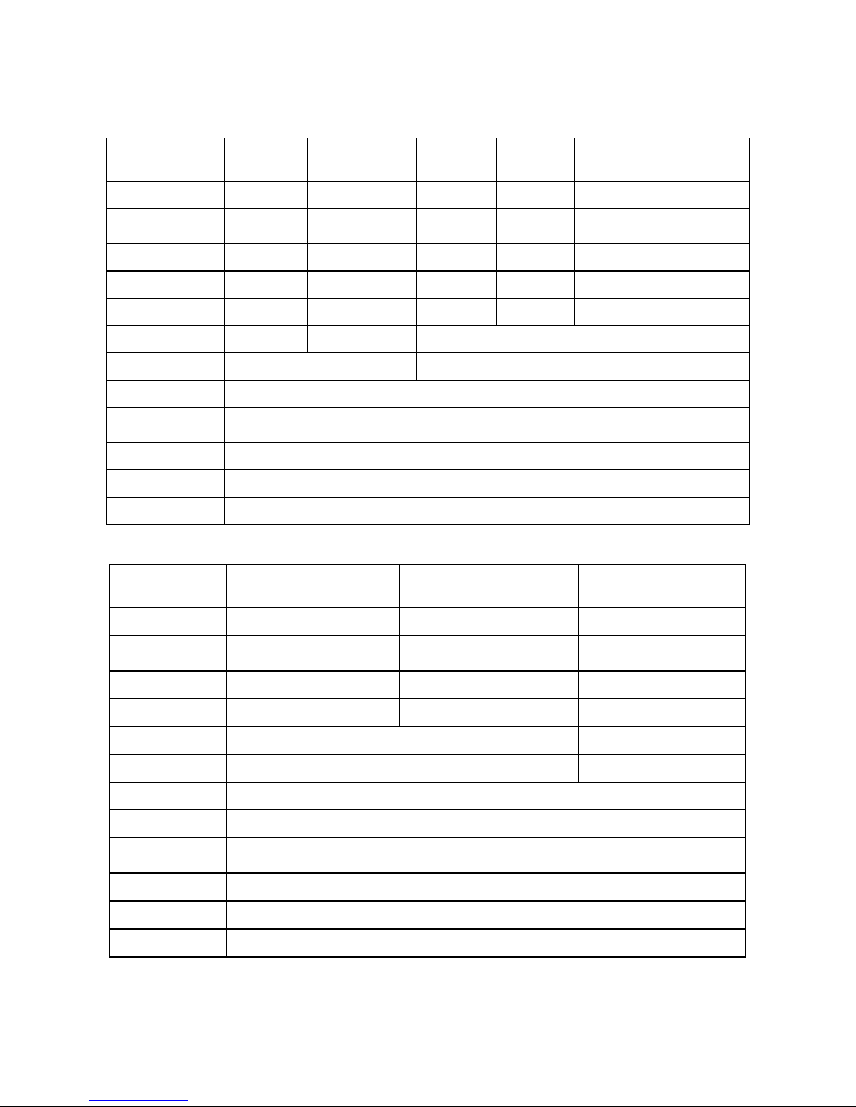
1. TECHNICAL DATA
AS
60/C/2
AS
60/220/C/2
AS
110/C/2
AS
160/C/2
AS
220/C/2
AS
310/C/2*
Max capacity
60g
60/220g
110g
160g
220g
310g
Minimum
weight
1mg
1mg
10 mg
10 mg
10 mg
10 mg
Readability
0,01mg
0,01/0,1mg
0,1 mg
0,1mg
0,1mg
0,1mg
Tare range
-60g
-220g
-110 g
-160 g
-220 g
-310 g
Repeatability
0,04mg
0,04/0,1mg
0,1 mg
0,1 mg
0,1 mg
0,1 mg
Linearity
±0,07mg
±0,07/0,2mg
±0,2mg
±0,3mg
Pan size
Φ 70 mm
Φ 85 mm
Sensitivity drift
1 ppm/°C in temperature +15 ° - +35 °C
Working
temperature
+10 ° - +40 °C
Power supply
13,5 - 16V DC / 1,1 A
Adjustment
internal (automatic)
Display
LCD with backlight
* - non-verified balance
APS 120/C/2/CT APS 220/C/2/CT APS 320/C/2/CT
Max capacity
120g/600ct 220g/1100ct 320g/1600ct
Minimum
weight
0,02g/0,1ct 0,02g/0,1ct 0,02g/0,1ct
Readability
0,0002/0,001ct 0,0002g/0,001ct 0,0002g/0,001ct
Tare range
-120g/-600ct -220g/-1100ct -320g/-1600ct
Repeatability
0,0002g/0,001ct 0,0004g/0,002ct
Linearity
±0,0002g/0,001ct ±0,0004g/0,002ct
Pan size
Φ 85 mm
Sensitivity drift
2 ppm/°C in temperature +15 ° - +35 °C
Working
temperature
+10 ° - +40 °C
Power supply
13,5 - 16V DC / 1,1 A
Adjustment
internal
Display
LCD with backlight
Page 6

- 6 -
Dimensions
Balance series:
AS 60/C/2
AS 60/220/C/2
AS 110/C/2
AS 160/C/2
AS 220/C/2
AS 310/C/2
Balance series:
APS 120/C/2/CT
APS 220/C/2/CT
APS 320/C/2/CT
Page 7

- 7 -
2. BASIC INFORMATION
2.1. Intended use
Analytical balance AS series serves to determine the weighing value of loads in
laboratory environment. It is intended for application as a non-automatic
weighing instrument only, i.e. the material to be weighed is manually and
carefully placed in the center of the weighing pan. Weighing result should be
read only after stable reading has been obtained.
2.2. Inappropriate use
Do not use the balance as a dynamic weighing instrument. Even if small
quantities of weighed material are added or removed from the weighing pan of
the instrument, the reading should be taken only after stabilization of the
measurement result. Do not place any magnetic materials on the weighing pan,
as this can cause damage of the measuring system of the instrument. Be sure
to avoid impact shock and overloading the balance in excess of the prescribed
maximum measuring range (max capacity), minus any possible tare weight that
has been applied. Never use the balance in an environment endangered by an
explosion. This balance has not been adjusted for operation in explosive areas.
There must not be any modification made to the balance.
2.3. Warranty
Warranty is not valid at the following:
• Non-observation of the guidelines of this user manual,
• Use of balance other than specified in this manual,
• Alternation to or opening of the device,
• Mechanical damage and damage caused by media, natural water,
and tear,
• Inappropriate assembling or defects of electric installation,
• Overloading of the measuring instrument.
Page 8

- 8 -
2.4. Monitoring metrological parameters of the instrument
Metrological characteristics of the balance requires periodical inspection
carried out by its operator. Inspection frequency is conditioned by ambient
conditions in which the balance is used, types of performed processes and
accepted quality management system in an organization.
2.5. Data included in this user manual
Please read the user manual carefully before assembling and startup, even if
the user is experienced with this type of weighing instruments.
2.6. Staff training
This balance should only be operated and maintained by personnel who is
trained and experienced in using this type of balances.
3. TRANSPORT AND STORAGE
3.1. Delivery check
Please check the packaging immediately upon delivery and the device during
unpacking for any visible signs of external damage.
3.2. Packaging
Please retain all parts of the original packaging should the balance be
transported in the future. Only the original packaging should be used for
dispatching the balance. Before packing, disconnect all attached cables and
remove any loose/movable parts (weighing pan, anti-draft shields, etc.). Please
place balance and its components in their original packaging, and protect them
against damage during transport.
Page 9

- 9 -
4. UNPACKING, ASSEMBLING AND STARTUP
4.1. Assembling, and place of use
• Balance should be stored and used in locations free of vibrations and
shakes, free of air movement and dust,
• Ambient air temperature should not exceed the range of: +10
o
C ÷ +40oC
• Ambient relative humidity should not exceed 80%
• During balance operation, ambient temperature in the weighing room should
not change more than 0,5°C within one hour,
• The balance should be located on a stable wall console desk or a stable
working table which is not affected by vibrations and distant from heat
sources,
• Take special safety measures when weighing magnetic objects, as part of
the balance is a strong magnet. Should such loads be weighed, use under
hook weighing option, which removes the weighed load from area influenced
by the balance’s magnet. For assembling the hook for under hook weighing
option see the bottom section of balance’s housing,
• In order to avoid influence of static electricity on the measurement process,
ground the balance’s housing. the grounding bolt is located at the back of
balance’s housing.
Page 10

- 10 -
4.2. Unpacking
Carefully remove the balance from its packaging, remove the plastic and foil
transport protective elements and gently place the balance in its intended place
of use. Assemble the weighing pan, and other elements according to below
scheme:
Balance with weighing pan Φ 70 mm:
- open side doors of the weighing
chamber,
- inside the weighing chamber place lower
shield of the weighing chamber (1),
- put centering ring (2) [framing facing
downwards] onto the weighing
chamber’s shield,
- in the center of centering ring assembly
the weighing pan (3),
- assembly anti-draft shield (4) on the
centering ring and weighing chamber’s
shield,
- close side doors of the weighing
chamber,
- plug the balance to mains,
pin of power adaptor should be
connected to socket in the back of
balance housing.
Page 11
- 11 -
Balance with weighing pan Φ 85 mm:
- open side doors of the weighing
chamber,
- inside the weighing chamber place
lower shield of the weighing chamber
(1),
- put centering ring (2) [framing facing
downwards] onto the weighing
chamber’s shield,
- in the center of centering ring
assembly the weighing pan (3),
- assembly anti-draft shield (4) inside
the weighing chamber,
- close side doors of the weighing
chamber,
- pin of power adaptor should be
connected to socket in the back of
balance housing.
4.3. Leveling
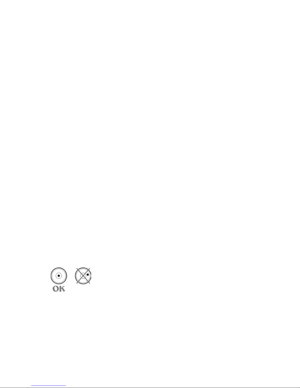
Before plugging to mains, level the device using two adjusting
feet located at the back of balance’s housing. Turn the
adjusting feet in a way that the air bubble of the level is placed
centrally. The level is located at the back wall of balance’s
housing.
Page 12

- 12 -
4.4. Standard equipment
• Balance.
• Weighing pan and protecting (anti-draft) components.
• Power adapter.
• User manual.
4.5. Cleaning
Balance should be cleaned with damp cloth by gentle wiping the smudges of
dirt. In order to clean the weighing pan of the balance, please remove it from
the weighing chamber. Cleaning of the pan when assembled may cause
damage of the measuring system of the balance.
4.6. Plugging to mains
Balance can be plugged to mains only with a power adapter that comes
standard with the balance. Nominal power supply of the power adapter
(specified on the data plate of the power adapter) should be compatible to the
power from mains. Plug the balance to mains – the plugging socket is located
at the back of balance’s housing. Balance display will light and show name and
number of software, after which balance will display 0.0000g. If indication is
other than zero, please press ESC/TARE key.
4.7. Connecting peripheral devices
The balance must be unplugged from the mains before connecting or
disconnecting any peripheral devices (printer, PC computer). Use only
peripheral devices recommended by the manufacturer with your balance.
These have been ideally coordinated to your balance. On connecting a
peripheral device, plug the balance to mains.
5. BASIC FUNCTIONS
• functions related to m ea suring units
- setting default measuring unit <StUn>,
- weighing in grams [g],
- weighing in milligrams [mg],
- weighing in carats [ct],
- weighing in units from beyond SI (available only in non-verified
balances): [oz], [ozt], [dwt], [t], [mom], [gn],
Page 13

- 13 -
• functions related to working modes
- parts counting <PcS>,
- checkweighing (+/- control) <HiLo>,
- percent setup <PrcA>, <PrcB>,
- density determination of liquid <d_Li>,
- density determination of solids <d_Co>,
- pipettes calibration <PiPEt>
- FiLL mode <FiLL>
• functions related to se tting a balance to ambient and working conditions
at a workstation
- enabling / disabling autozero system <Auto>,
- setting the parameter of measurement result averaging <AuE>,
- measurement result value release <ConF>,
- weighing mode <rAPd>,
- display backlight <bl>,
- beep signal (balance reacion on pressing a function key) <bEEP>,
• functions related to use of RS 232 interface
- setting baud rate <bAud>,
- Continuous data transmission in basic measuring unit <CntA>,
- Continuous data transmission in current measuring unit <Cntb>,
- Automatic operation mode <rEPL>.
Balance As series can be used to weigh loads under the weighing platform – i.e.
under hook weighing option.
Balance software enables printing a report from adjustment process and carrying
out adjustment test.
Page 14
- 14 -
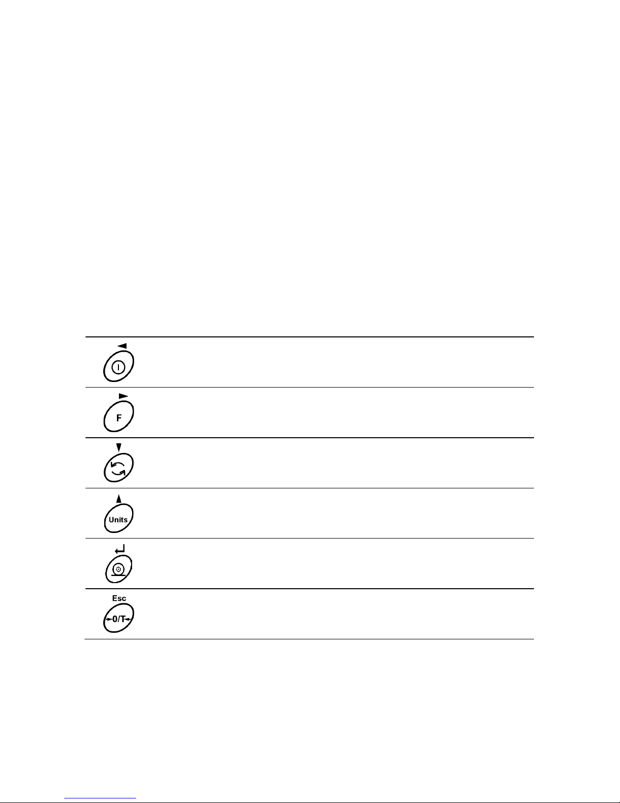
6. KEYBOARD
ON/OFF key; enables turn
ing on and off balance’s display. If turned
off, balance components other than the display are powered, and
balance is in stand-by mode.
F key; function key.
MODE key; for selecting working mode.
UNITS key; changes measuring units.
PRINT/ENTER
key; sends current display status to a peripheral
device (PRINT) or accepts selected value of a parameter or function
(ENTER).
ESC/TARA key; zeroing display indication.
Page 15

- 15 -
7. START-UP
When plugged to mains, the balance displays name and number of software, and afterwards
proceeds to weighing mode.
Balance temperatur e s t abilization period.
Before start of measuring processes, it is necessary to wait until the balance is
thermally stabilized. It is a period of so called balance self-heating. In case of
balances AS and APS series self-heating period takes approximately 30 minutes.
The specified time interval refers to balances that have been stored in room
temperature before plugging to mains.
For balances that were stored in much lower temperatures before plugging to mains
(e.g. during winter period) thermal stabilization should last approximately 4 hours.
Correct operation of a balance is possible within temperature range specified in the
technical parameters, see point 1. If the balance is placed in area which ambient
temperature is out of temperature range specified in the technical data, then
balance’s display may signal such situation by lighting an appropriate marker (a
black triangle).
In case the balance displays the marker, increase or decrease ambient
temperature, depending on present temperature value. It is recommended that
ambient temperature changes at balance’s place of use are very small (slow).
Page 16
- 16 -
8. USER MENU
Balance menu is divided into 7 basic function groups. Each group has individual
name starting with capital letter P.
8.1. Moving through user menu
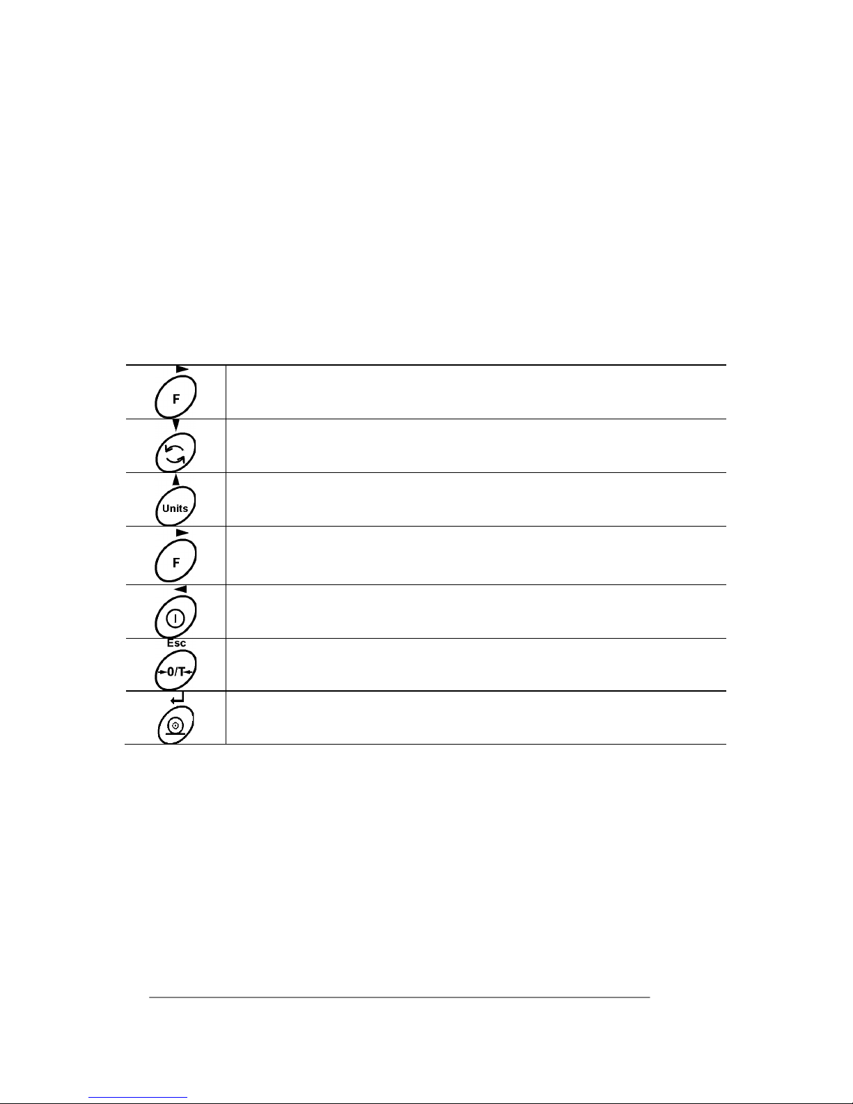
An operator moves through balance menu using keys on overlay’s keyboard:
Entering main menu. F function key.
Selecting group of parameters one by one downwards or
changing parameter value by one value downwards. MODE key.
Selecting group of parameters one by one upwards or changing
parameter value by one value upwards. UNITS key.
Selecting group of parameters for activating. On pressing the
key, the display indicates the first parameter in a selected group.
F key.
Exit to previous menu level, e.g. to the main menu. ON/OFF key.
Abandon parameter changes. Esc/TARE key.
Accept / confirm introduced changes. PRINT/ENTER key.
Name of function groups and their content:
P1 CAL [Adjustment/Calibration]
P1.1 iCAL | [internal adjustment]
P1.2 ECAL | [external adjustment]
P1.3 tCAL | [temperature adjustment]
P1.4 ACAL | both/nonE/tenno/tinnE [automatic adjustment]
P1.5 CALt | 1 h ÷ 12h [time of automatic adjustment]
P1.6 CALr | YES/no [report from adjustment]
Page 17

- 17 -
P2 GLP [Good Laboratory Practice]
P2.1 USr | _ [name of user]
P2.2 PrJ | _ [name of project]
P2.3 Ptin | YES/no [printout of measurement time]
P2.4 PdAt | YES/no [printout of measurement date]
P2.5 PUSr | YES/no [printout of user name]
P2.6 PPrJ | YES/no [printout of project name]
P2.7 PId | YES/no [printout of balance’s factory number]
P2.8 PFr | YES/no [printout of frames]
P3 rEAd [Main user parameters]
P3.1 AuE | Stand/Slouu/FASt [filtering level]
P3.2 ConF | FASt_rEL/Fast/rEL [value release]
P3.3 Auto | On/OFF [autozero]
P3.4 Ldi9 | ALuuAYS/neper/uu_StAb [blanking last digit]
P3.5 rAPd I YES/no [weighing mode RAPID]
P4 Print [Data transmission – RS 232]
P4.1 bAud | 2400/4800/9600/19200 [baud rate]
P4.2 CntA | YES/no [continuous printout in basic measuring unit]
P4.3 Cntb | YES/no [continuous printout in current measuring unit]
P4.4 rEPL | YES/no [manual or automatic operation]
P4.5 PStb | YES/no [measurement result printout: stable or unstable]
P4.6 Lo | 000.0000 [min mass threshold for automatic operation]
P5 Unit [Measuring units]
P5.1 StUn | g/mg/ct/oz/ozt/dwt/t/mom/G [basic measuring units – e,g, gram]
P5.2 mg | YES/no [mg - millligram]
P5.3 Ct | YES/no [ct – carat]
P5.4 oZ | YES/no [oz – ounce]
P5.5 oZt | YES/no [ozt – ounce troy]
P5.6 dwt | YES/no [dwt – pennyweight]
P5.7 t | YES/no [t – tael]
P5.8 nno | YES/no [mom - momme]
P5.9 Gr | YES/no [gr – grain]
P6 Func [F
unkcje]
P6.1 FFun | ALL/PcS/HiLo/PrcA/Prcb/d_Co/d_Li/PipEttE/FiLL
working mode selection]
P6.2 PcS | YES/no [parts counting]
Page 18

- 18 -
P6.3 HiLo | YES/no [checkweighing]
P6.4 PrcA | YES/no [percent setup with reference to
weighed standard]
P6.5 Prcb | YES/no [percent setup with reference to
declared standard]
P6.6 d_Co | YES/no [density determination of solids]
P6.7 d_Li | YES/no [density determination of liquids]
P6.8 Pi_t I YES/no [pipettes calibration]
P6.9 Fill I YES/no [working mode FiLL]
P7 othEr [Other functions]
P7.1 bL | On/Aut/OFF [display backlight]
P7.2 bEEP | On/OFF [beep sound on pressing keys]
P7.3 PrnS | [printout of balance parameters]
8.2. Return to weighing mode
CAUTION
Changes introduced in balance memory will be permanently saved
on return weighing with procedure of saving changes.
Press ESC/TARE key for several times, until the display
indicates command SAvE?.
Then select one of below option:
PRINT/ENTER key – save (accept) changes
or ESC/TARE
key – abandon introduced changes, and
leave to balance menu.
After pressing an appropriate key, the balance goes back to
weighing mode.
Page 19

- 19 -
Page 20

- 20 -
9. WEIGHING
Before start of weighing process or in case of essential change of ambient
conditions at a workstation (e.g. ambient temperature change at a workstation more
than 0,8°C) the balance requires adjusting. The procedure of balance adjustment is
described further in this user manual.
• Before start of weighing procedure, it is recommended to load the balance’s
weighing pan a few times with mass close to balance max capacity,
• Check if unloaded balance indicates “precise zero” -
and whether
measurement is stable - , if not press ESC/TARE key,
• Press UNITS key to set a measuring unit:
[g], [mg], [ct], and also if enabled in factory menu [oz], [ozt], [dwt], [t], [mom],
[gn],
• place weighed object on balance’s weighing pan and read result only on
stabilization of measurement result,
• mass indication of a load placed on balance’s weighing pan can be tarred for
multiple times by pressing ESC/TARA key (pay attention not to exceed
maximal capacity of a balance by applying multiple tare function).
During times between carrying out the following measurement series do not unplug
the balance from mains. It is recommended to switch off balance’s display by
pressing ON/OFF key. On repeated pressing of the ON/OFF key the balance is
ready for operation and carrying out the following measurements.
In order to adjust the balance’s operation (while weighing small mass
≤0,6g) to ambient conditions at a workstation, it is recommended to set
the following:
- filtering level AuE to: the slowest
- value release ConF to: reliable
Page 21

- 21 -
9.1. Selection of basic measuring unit
Function is used to set the measuring unit which will be displayed on balance
switching on.
In order to set the measuring unit go to submenu P5 Units
press UNITS key for a few times. The display indicates available measuring
units in turns.
Page 22

- 22 -
After selecting the basic measuring unit press PRINT key. The balance returns
to displaying parameter name.
Available settings:
• For verified balances, a user can select from the following measuring units:
[g], [mg], [ct];
• For non-verified balances, a user can select from the following measuring
units: [g], [mg], [ct], [oz], [ozt], [dwt], [t], [mom], [gn].
Go back to weighing mode with procedure of saving changes
(see point - 7.1.2. – return to weighing).
CAUTION:
On switching on, the balance will start operating with set basic measuring
unit.
9.2. Temporary measuring unit
Function enables selecting a measuring unit which will be indicated next to
mass readout during weighing process. Set measuring unit will be in use from
the moment of its activation until its change or switching off and on the balance.
Each pressing the Units key, causes change of the measuring unit.
Available settings:
• For verified balances, a user can select from the following measuring units:
[g], [mg], [ct];
• For non-verified balances, a user can select from the following measuring
units: [g], [mg], [ct], [oz], [ozt], [dwt], [t], [mom], [gn].
Page 23

- 23 -
9.3. Setting accessibility of balance working modes
This group of parameters enables the user to declare functions (working
modes) which are accessible on pressing of MODE key.
Enter group of parameters P6 Func,
9.3.1. Selection of working modes available for a user
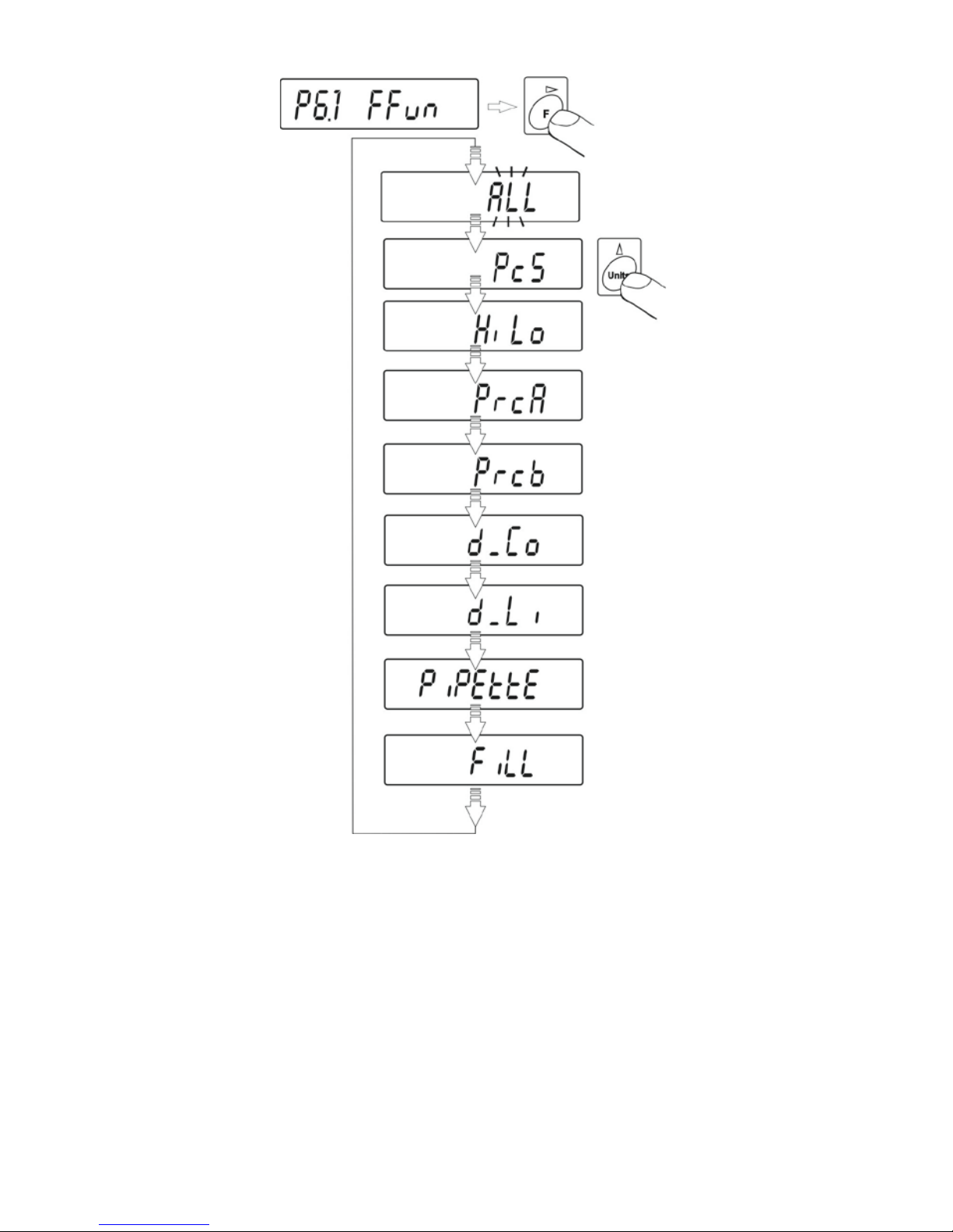
Function enables selecting (by pressing MODE key) which working modes
are accessible during weighing function – if all – then select (ALL) and if
only one from all available (described below).
Page 24
- 24 -
After setting the parameter press PRINT key. Balance goes back to
displaying submenu name P6.1 FFun.
If a mode other than ALL is selected, procedure of returning to weighing
mode differs from other ones.
If for instance PcS mode is selected, follow procedure in accordance with
point 14.1 point, to return to weighing:
Page 25

- 25 -
Press Esc/TARE key, balance returns to weighing.
9.3.2.
Means of selecting one of available working modes
Balance user can enable or disable modes which are not used in the
weighing process. This provides quicker access to modes used on a
balance.
Page 26
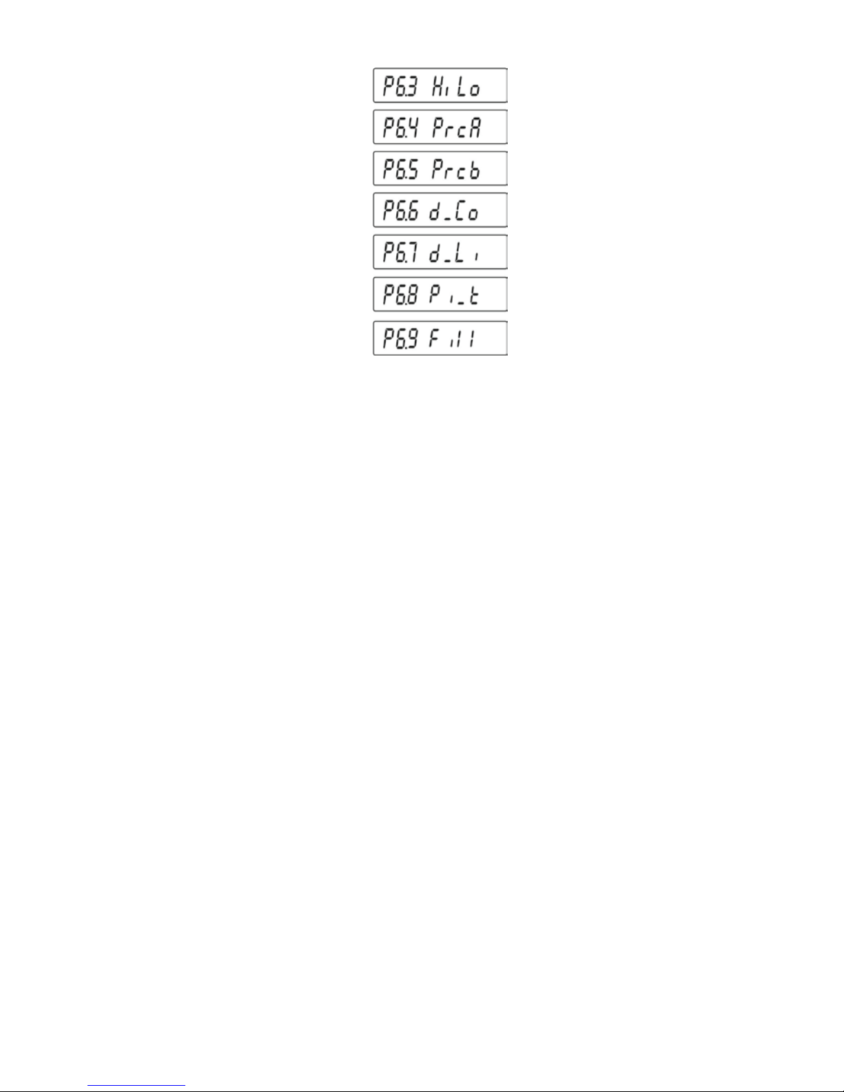
- 26 -
YES - mode available;
no - mode disabled
On making a choice press PRINT key. The balance returns to displaying
submenu name.
Go back to weighing mode with pro c edure of saving changes
(see point - 7.1.2. – return to weighing).
Page 27

- 27 -
10. BALANCE MAIN PARAMETERS
It is possible to adjust balance’s operation to ambient conditions at a workstation
(by setting filter range and value release parameters) or user requirements
(autozero settings, last digit visibility). These parameters are set in group P3
rEAd.
10.1. Setting level of filtering
- using UNITS key to select desired value of filter settings,
StAnd - (normal) – normal operation conditions
Slouu - (slow) – harsh operation conditions - vibrations, etc.
Fast - (fast) – good operation conditions – no vibrations, etc.
Return to weighing mode with procedure of saving changes
(see point – 8.2. – return to weighing).
CAUTION:
The higher filtering setting the longer weighing time.
Page 28

- 28 -
10.2. Value release
Due to various ambient conditions at workstations, and in order to set balance
to present conditions, it is necessary to determine the value release parameter
as: FAST_rEL, Fast or rEL. Depending on selected option, weighing time will
be shorter or longer.
Fast_rEL - fast + reliable
Fast - fast
rEL - reliable.
Return to weighing mode with procedure of saving changes
(see point – 8.2. – return to weighing).
Page 29

- 29 -
10.3. Autozero function
In order to ensure balance’s precise mass indication, autozero (Auto) software
parameter has been introduced. The application of this function is automatic
control and correction of zero indication. When function is enabled, it
compares balance indications at declared time interval e.g. 1 s, on conditions
that weighing pan is unloaded and display indication is close to zero.
If results vary less than declared AUTOZERO range e.g. one division, balance
will zero automatically, display marker of stable measurement result
and
precise zero marker
.
If AUTOZERO function is enabled, then each weighing process starts from
precise zero point. There are, however, some cases when this function can be
a disturbing factor of measuring process; for instance very slow placing of load
on the weighing pan (e.g. load pouring) – in such case system of zero
indication correction can also correct actual indication of loaded mass.
OFF – autozero disabled
On – autozero enabled.
Return to weighing mode with procedure of saving changes
(see point – 8.2. – return to weighing).
Page 30

- 30 -
10.4. Blanking of last digit on the display
Function enables blanking of the last displayed digit.
ALuuAYS – always
nEuEr – never
uu_StAb – when measurement result is stabilized.
Return to weighing mode with procedure of saving changes
(see point – 8.2. – return to weighing).
Page 31
- 31 -
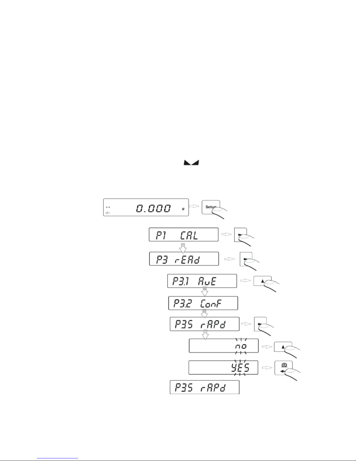
10.5. Weighing mode RAPID
Weighing mode RAPD is located in menu parameter P3.rEAd and it offers two
options:
RAPID = NO – balance operates with settings as set in menu AUE and CONF,
i.e. standard weighing.
RAPID = YES – (default settings) balance operates with settings specific for
software mode “FILL”, and:
- The value of CONF parameter is automatically set to: Fast+rel,
independently on previous setting of this parameter;
- The value of AuE parameter is automatically set to: Standard,
independently on previous setting of this parameter;
-
The value of Stabilization time parameter is automatically decreased
(factory setting is decreased by 4). Such parameter setting speeds up
the time of stability pictogram
appearance on the display.
The values of AuE and CONF parameters are editable if mode rAPd is enabled
for setting shorter or longer measurement time.
Mode enabling or disabling
Return to weighing mode with procedure of saving changes
(see point – 8.2. – return to weighing).
Page 32

- 32 -
11. OTHER PARAMETERS
Balance AS series features a set of parameters which enable influencing its
functionality. The parameters are contained in group: P7 othEr and they are:
backlight and “beep” signal and printout of all balance parameters through RS 232
port.
In order to edit the above parameters enter menu group P7 Other.
11.1. Backlight of weighing result (display backlight)
OFF – backlight disabled
On – backlight enabled
Aut – backlight disabled automatically if weighing result does not
change within10 seconds.
Return to weighing mode with procedure of saving changes
(see point – 8.2. – return to weighing).
CAUTION:
Balance software has implemented option of automatic backlight switch off
bl = Aut. In case of this setting, the back light is switched automatically off
if weighing results does not change within 10 seconds. Backlight is
automatically activated at the moment of weighing result change on
balance display
Page 33

- 33 -
11.2. “Beep” sound – reaction on pressing a function key
OFF – signal of pressing function key disabled
On – signal of pressing function key enabled.
Return to weighing mode with procedure of saving changes
(see point – 8.2. – return to weighing).
11.3. Printout of all balance parameters through RS 232 port
After pressing F key balance parameters are sent to a peripheral device
connected to balance’s RS 232 port.
Return to weighing mode with procedure of saving changes
(see point – 8.2. – return to weighing).
Page 34

- 34 -
12. BALANCE ADJUSTMENT
As the gravitational acceleration force has different value at various latitudes and
altitudes, a balance should be adjusted to present working conditions. This process
should take place at the first installation of the instrument on site and at its every relocation – as in case of ambient temperature changes.
In order to ensure the highest weighing accuracy, it is recommended to periodically
introduce to balance memory a corrective factor of indications in relation to a mass
standard – i.e. balance adjustment.
Adjustment should be carried out:
- Before the beginning of weighing procedure,
- If long breaks between following measuring series occur
- If temperature inside the balance changes more than: 0,8°C.
Types of adjustment:
- Internal automatic adjustment
* triggered by temperature change
* triggered by elapsing time
- Manual internal adjustment
* initiated from balance’s keyboard
- Adjustment with external weight
* with declared mass which cannot be modified.
CAUTION
In case of verified balances (with internal automatic adjustment system)
only the automatic internal adjustment and manual internal adjustment
system are available for a user.
In verified balances PS series with external adjustment system, adjustment
process is blocked (not available) for a user.
Perform the calibration when there is no load on the pan!
Remember to carry out adjustment process only when there is no load on
the weighing pan! In case there is load on the weighing pan, the display
will indicate a command Er1 Hi. It is comment of unloading the pan.
Adjustment process can be aborted if necessary by pressing Esc/TARE
key.
Page 35

- 35 -
12.1. Internal adjustment
Adjustment process can be initiated automatically or manually.
Manual means of activating adjustment procedure is realized by pressing F key
on balance’s keyboard. System of automatic adjustment will carry out the
process fully automatically inform the operator on successive process stages.
Cycle of automatic adjustment process:
- balance software detects necessity of carry out adjustment and
signalizes it by Celsius degree pictogram or by black colour pictogram on
balance display
- since pictogram occurrence, time interval of 5 minutes is counted
within which weighing procedure can be completed
- as the 5 minutes time elapses, balance display indicates message CAL_30
and starts counting down from 30..29..28 to 0 (indicated value is the
counter),
- balance user has 30 seconds to make a decision:
in order to start adjustment, do not take any actions
in order to complete weighing procedure, press ESC/TARE key, If
pressed, balance returns to weighing procedure and displays last
weighing result. In 5 minutes balance will again indicate CAL_30
message.
- the adjustment process can be postponed for multiple times, but it needs to
be stressed that long postponing of adjustment may be a reason of bigger
errors of weighing process. The errors are effect of temperature changes
and as a consequence changes of balance sensitivity.
Page 36

- 36 -
Automatic adjustment process takes place in three different cases:
• adjustment on plugging the balance to mains. After approximately 6
minutes from plugging the balance to mains, it automatically initiates
adjustment process.
• Balance AS series is equipped with very precise system for
monitoring temperature. At each adjustment process, the temperature
is saved in system. The next adjustment is automatically initiated if
temperature changes more than: 0,8°C from last saved temperature
in case of balance AS series,
• adjustment triggered by elapsing time. It is possible to declare time
intervals which are a criteria for balance adjustment. Accessible
settings are: adjustment after 1, 2, 3, 4, 5, 6, 7, 8, 9, 10, 11, 12 hours
since last carried out adjustment procedure.
CAUTION
Declaring time interval for balance adjustment is available only in
non-verified balances. In case of verified balances the time interval
between following adjustments is set for 3 hours
Page 37

- 37 -
12.2. Settings of menu: Adjustment
P1 CAL
P1.1 iCAL |
P1.2 ECAL |
P1.3 tCAL |
P1.4 ACAL | both
P1.5 CALt | 1 h
P1.6 CALr | YES
• P1.1 iCAL – Internal adjustment
Start of internal adjustment process. Adjustment is conducted automatically,
and no operator assistance is required. If weighing pan of the balance is
loaded, balance will display a command to unload the weighing pan. If
weighing pan is loaded with relativaly small mass (up to 4 % of balance max
capacity) than adjustment process will be carried out automatically, but
measuring results may differ by the amount that was present on balance
weighing pan.
• P1.2 ECAL - External adjustment (with an external weight)
Adjustment with external weight, which value is saved in factory menu of
balance, function unavailable in verified balances.
• P1.3 tCAL – Adjustment test
Mass comparison of internal adjustment weight with its value saved in
balance memory.
• P1.4 ACAL – Automatic adjustment
Page 38

- 38 -
Determination of factor, which conditions start of automatic internal
adjustment.
nonE - none of factors will cause start of adjustment
tEmP - adjustment triggered by change of temperature
timE - adjustment triggered by time interval set in parameter P1.5 CA Lt
both - adjustment triggered by time and temperature.
Page 39

- 39 -
• P1.5 CALt - Time of automatic adjustment (balances with internal
adjustment system)
Determination of time interval, after which automatic adjustment process is
initiated.
• P1.6 CALr – printout of adjustment report
Printout activated on completion of automatic adjustment procedure.
no – report printout disabled
YES – report printout enabled.
Return to weighing mode with procedure of saving changes
(see point – 8.2. – return to weighing).
Page 40

- 40 -
12.3. Adjustment test
Adjustment test is a comparison of internal adjusting weight with its value
stored in balance’s memory. This process is automatic and its result is
shown on the display (if a balance is connected to a computer or a printer
through RS 232 socket, data on adjustment test is printout). Press
ESC/TARE key to return to previous display.
Return to weighing mode with procedure of saving changes
(see point – 8.2. – return to weighing).
Page 41

- 41 -
12.4. Manual adjustment
12.4.1. Internal adjustment
Press F function key for three (3) times.
The balance automatically enters internal adjustment mode. During
adjustment process do not load the weighing pan with any load.
On completion of adjustment process, balance saves its result in memory
and returns to weighing mode.
CAUTION:
- Press ESC/Tare key to abort adjustment process
- If during adjustment process, weighing pan of a balance is
loaded, than balance display will show order informing on error
occurrence. Adjustment process will be stopped. As weighing pan is
unloaded, the adjustment process will continue and complete.
Page 42

- 42 -
12.4.2. External adjustment
The external adjustment in balances AS series should be carried out with
an external mass standard / weight class E
2
.
Start of external adjustment process,
Balance will display a command ordering unloading of weighing pan
unloAd (weighing pan should be empty). When weighing pan is unloaded,
press PRINT key. The balance determines mass of empty pan. Place an
external adjustment weight with mass determined on balance’s display and
press PRINT key. On completing adjustment process the balance returns
to submenuP1.2 ECAL.
Return to weighing mode with procedure of saving changes
(see point – 8.2. – return to weighing).
If a balance is verified, then user does not access to carrying out
external adjustment process.
Page 43

- 43 -
12.5. Adjustment report printout
On completion of any type of adjustment process, the balance enables
preparing a report from adjustment process. The report can be printed on a
connected printer and sent to a computer and saved in a form of file for
records. Printout process is described in details in point 9.2 of this user manual.
The user can select between two options.
no – report is not printed
YES – report is printed
Remember, that if the parameter is set for YES, then a report is generated and
sent automatically.
Content of report from adjustment process depends on settings of GLP
parameters. Any option in the GLP submenu which attribute is YES is included
in a report from adjustment process.
P2 GLP (Good Laboratory Practice)
P2.1 uSr |
P2.2 PrJ |
P2.3 Ptin | YES
P2.4 PdAt | YES
P2.5 PuSr | YES
P2.6 PPrJ | YES
P2.7 PId | YES
P2.8 PFr | YES
Apart from information set in menu group the report contains:
• Mass of adjustment weight stored in balance’s memory from last
carried out adjustment;
• Mass of adjustment weight determined in current adjustment process;
• Adjustment deviation, i.e. difference between the two mass records.
Page 44

- 44 -
13. DETERMINING CONTENT OF A PRINTOUT FOR GLP PROCEDURES
P2 GLP, is group of the parameters which enables declaring variables that are
present on an adjustment printout and printout activated after a measurement.
P2 GLP
P2.1 USr |
P2.2 PrJ |
P2.3 Ptin | YES
P2.4 PdAt | YES
P2.5 PUSr | YES
P2.6 PPrJ | YES
P2.7 PId | YES
P2.8 PFr | YES
• P2.1 USr
The parameter enables determining name of a operator who works with the
balance. User name contains maximally 8 alphanumeric characters. The name
is inserted using F, MODE, UNITS on balance’s keyboard and PRINT key.
Page 45

- 45 -
Accessible characters and their equivalents displayed by the balance:
An instance of a user name inserted to a balance using capital letters takes
below form:
OP1_WILK (operator 1 WILK)
An instance of a user name inserted to a balance using small letters takes
below form:
op1_wilk (operator 1 wilk)
• P2.2 PrJ
The parameter enables determining name of a project (e.g. related to a specific
type of weighing process).
An instance of project name inserted to a balance using capital letters takes
below form:
PRRADWAG
Page 46

- 46 -
An instance of project name inserted to a balance using small letters takes
below form:
prradwag
• P2.3 Ptin
Option determining presence of measurement time on a printout.
• P2.4 PdAt
Option determining presence of measurement date on a printout.
• P2.5 PUSr
Option determining presence of user name on a printout.
• P2.6 PPrJ
Option determining presence of project name on a printout.
• P2.7 PId
Option determining presence of balance factory number on a printout.
• P2.8 PFr
Option enabling printing frames on a printout.
For above parameters please select one of two available settings:
no – variable absent on a printout
YES – variable present on a printout
Return to weighing mode with procedure of saving changes
(see point – 8.2. – return to weighing).
Page 47

- 47 -
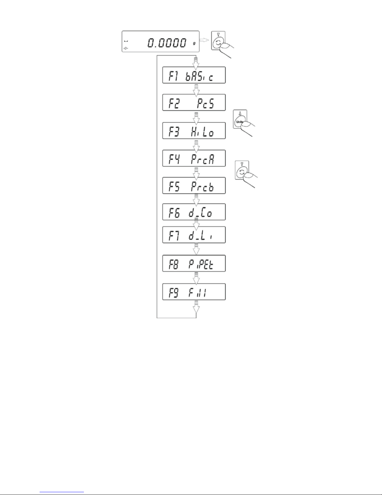
14. BALANCE WORKING MODES
- Weighing mode – bASic
- Parts counting – PcS
- Checkweighing – HiLo
- Percent setup with reference mass determined by weighing – PrcA
- Percent setup with reference mass determined by a user – PrcB
- Density determination of solids – d_Co
- Density determination of liquid – d_Li
- Pipette calibration – PiPEt.
- Working mode FiLL - FiLL
Press MODE key,
Page 48
- 48 -
Pressing MODE key causes displaying the first available mode. Each next
pressing of UNITS or MODE keys causes displaying name of next available
mode. The means of setting a working mode is described in further section of
this manual.
14.1. Parts counting of the same mass
Balance in its standard version is equipped with an option for counting parts
and small objects of the same unit mass. Parts counting mode does not
cooperate with other working modes.
• Enable PcS mode,
Page 49

- 49 -
• Press UNITS key to set sample quantity 10, 20, 50 or FrEE,
Page 50

- 50 -
• in order to select one of the options, e.g. 20 pcs press PRINT
key and proceed as shown on below figure,
Page 51

- 51 -
• If option FrEE (sample quantity is declared by a user) is selected, insert
sample quantity used for determining mass of single part,
• Press F key to select a digit to be altered, and press UNITS key to
change digit value,
• Accept inserted value by pressing PRINT key,
• Display indicates a command LoAd – load the weighing pan with as
many details as inserted while determining sample quantity,
• Press PRINT key – balance indicates sample’s quantity (pcs pictogram
is visible on the display),
• add remaining parts, the display indicates their total quantity.
Page 52

- 52 -
Return to weighing
CAUTION:
While determining sample quantity, and before accepting it, it is necessary
to wait until stable measurement pictogram
is displayed. Only if
visible on balance’s display, it is allowed to accept the declared quantity of
parts by pressing PRINT key. Otherwise balance will not accept the
measurement.
Page 53

- 53 -
14.2. Checkweighing (HiLo) with reference to set standard
• Enter the checkweighing mode,
During setting limit values the following relations occur:
Page 54

- 54 -
SET LOW LIMIT (LOW THRESHOLD)
F - digit selection; UNITS set digit value; PRINT - accept inserted digit value
SET HIGH LIMIT (HIGH THRESHOLD)
F - digit selection; UNITS - set digit value; PRINT - accept inserted digit value
Page 55

- 55 -
CAUTION:
If by mistake the value of low threshold is set higher than high threshold,
balance will indicate error message and return to weighing.
Return to weighing:
Page 56

- 56 -
14.3. Percent setup
Balance software enables controlling deviation (in %) of weighed loads with
determined reference mass. Mass of a reference load can be determined by
its weighing (PercA) or entered to balance memory by a user (PercB).
14.3.1. Reference mass determined by weighing
• Enter PrcA mode:
• on balance weighing pan place a load which mass will be accepted
as the reference,
• press PRINT to accept this working mode,
Page 57
- 57 -
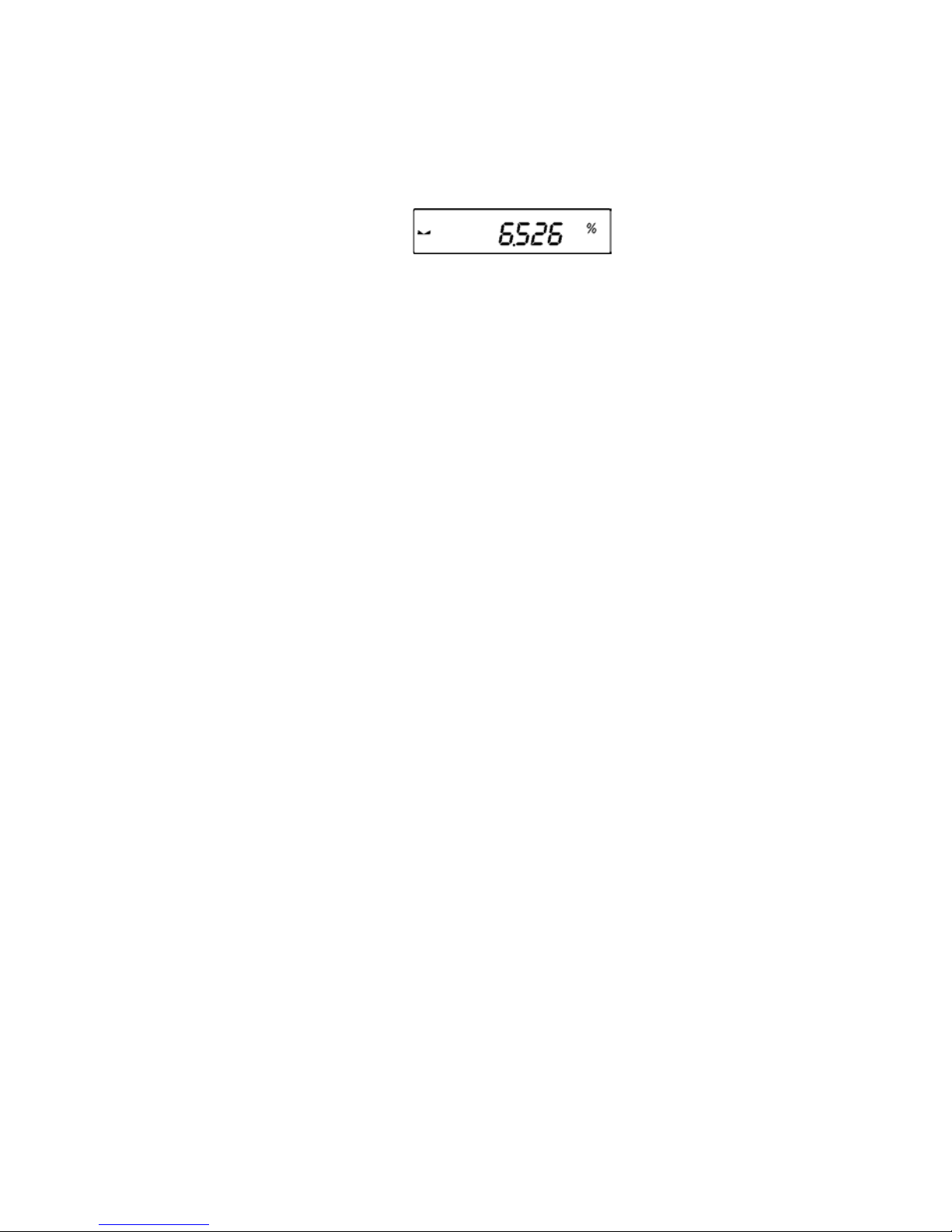
• after few seconds indication 100,00% will be displayed.
From now on the display will not indicate mass of weighed load but
deviation of mass placed on the pan in relation to the reference (in %).
14.3.2. Reference mass set in balance memory by a user
• Enter PrcB mode:
• Display will indicate as above,
• Using function keys:
F – Select a digit
Units – choose digit value
Page 58

- 58 -
• Determine the value of reference mass, insert it to balance
memory and accept it by pressing PRINT key – display will indicate:
0,00%
From now on the display will not indicate mass of weighed load but
deviation of mass placed on the pan in relation to the reference (in %).
Return to weighing
Page 59
- 59 -
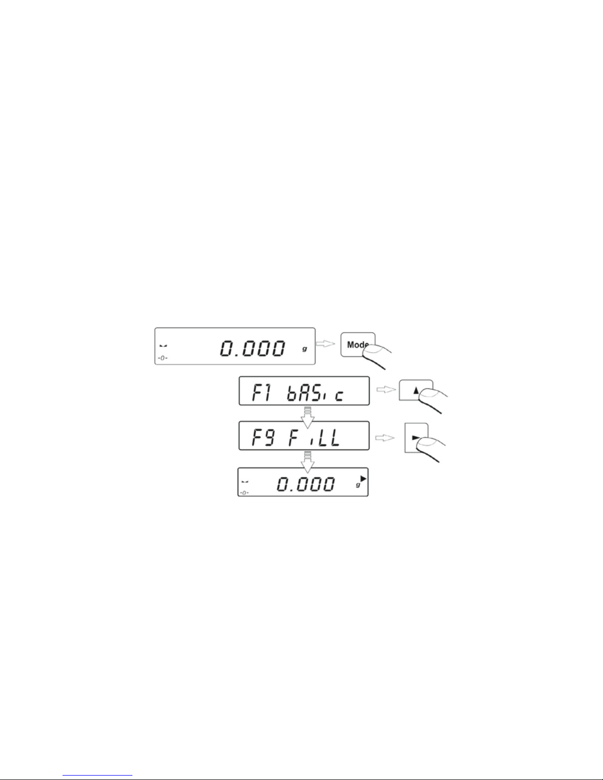
14.4. Working mode FILL
Working mode FiLL enables two settings:
FiLL = NO – mode disabled, i.e. not available in the working modes.
FiLL = YES – mode enabled, i.e. available in the working modes.
If FiLL is enabled, then the balances operates with settings, that are stored in
balance’s settings as default and ensuring quicker operation. The settings
automatically decrease Autozero range to 1 reading interval. Mode activation is
signaled by a black triangle pictogram visible on display’s right hand side (and
above the measuring unit). Working mode FiLL is set to YES as default, thus it
is accessible in the working modes. The mode can be disabled from the
working modes by setting it to NO. To disable FiLL mode enter menu of
available modes – see point 9.3.2 of this user manual.
Enabling FiLL mode in the working modes
The balance operates in accordance with the settings of AUE and CONF
options. The options enable setting shorter or longer measurement time.
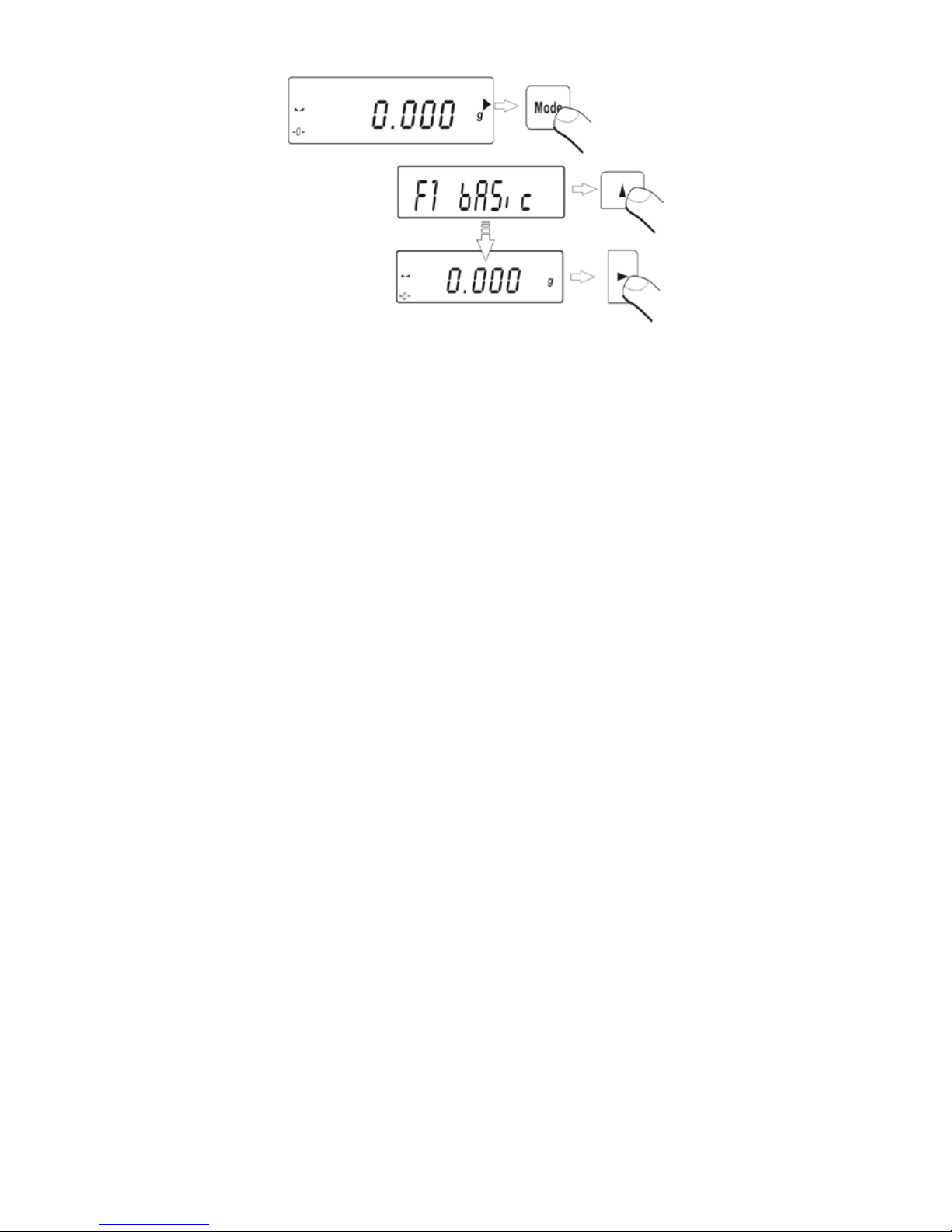
Disabling FiLL mode
Page 60
- 60 -
On disabling FiLL mode, the measurement are carried out in accordance with
user settings.
14.5. Density determination of solids and liquids
Optional equipment of balances AS series is a kit for determining density of
solids and liquids. In order to assemble the density kit on the balance, remove
the weighing pan and anti-draft shield from the balance. In the place of the
weighing pan assemble the weighing pan with stand (1) and place beaker’s
basis (2) on it.
Components of the density kit
1. Beaker support. 8. Sinker’s hook.
2. Weighing pan with stand. 9. Top weighing pan.
3. Sinker. 10. Flexible connector of weighing pans.
Page 61

- 61 -
4. Beaker. 11. Bottom weighing pan.
5. Thermometer handle. 12. Supplementary weights
6. Thermometer.
13. Additional stand for set of pans or a
sinker
7. Sinker’s flexible
connector.
14. Additional set of pans for determining
density of solids, which density is lower
than density of water
14.5.1. Density determination of solids
Density determination of solids can be carried out in two pre-defined types
of liquids or user-defined liquid with specified density:
• H2O (distilled water),
• C2H5OH (spirit 100% +/- 0.1% in temp. 20
0
C),
• AnotHEr (another liquid with specified density)
In case of determining density in water or alcohol it is necessary to specify
their temperature. For another liquid, its value (density) is inserted from
balance keyboard. Density determination is carried out by weighing a
sample first in the air (top weighing pan (9) of the density kit), and then
weighing the same sample in liquid (on the bottom weighing pan (11) of
the density kit). As the sample is weighed in liquid, the result of density
determination is automatically indicated on balance display.
14.5.2. Density determination of liquid
Basic element for determining density of liquids is a glass sinker (3). Its
volume is precisely determined and given on sinker’s hanger. Before
starting liquid density determination, insert the value of sinker’s volume to
balance memory. In order to measure the density of liquid, first determine
mass of the sinker in the air. Then measure mass of the same sinker in
tested liquid. The result of liquid density determination is automatically
indicated on balance display.
Page 62
- 62 -
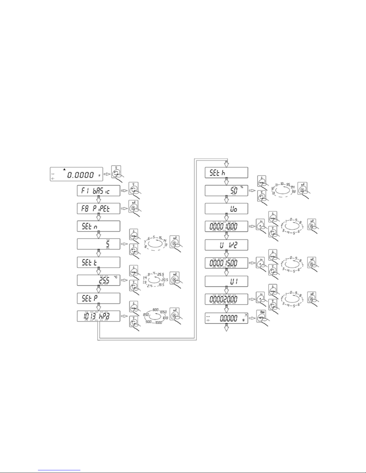
14.6. Pipettes calibration
Structure of pipettes calibration mode is very clear and intuitive. Basically, it
requires inserting data on ambient conditions, parameter of calibration process and
parameters of a tested pipette.
14.6.1. Data input
In order to start pipettes calibration mode and input required parameters for
calibration process, follow the instruction from below figures:
• Set n – set quantity of repetitions performed during pipettes calibration
(5 ÷ 15),
• Set t – set temperature in which pipettes calibration is conducted
(0,4 ÷ 25,5 °C),
• Set P – set pressure of a weighing room in which pipettes calibration is
conducted (800 ÷ 1050 hPa),
Page 63
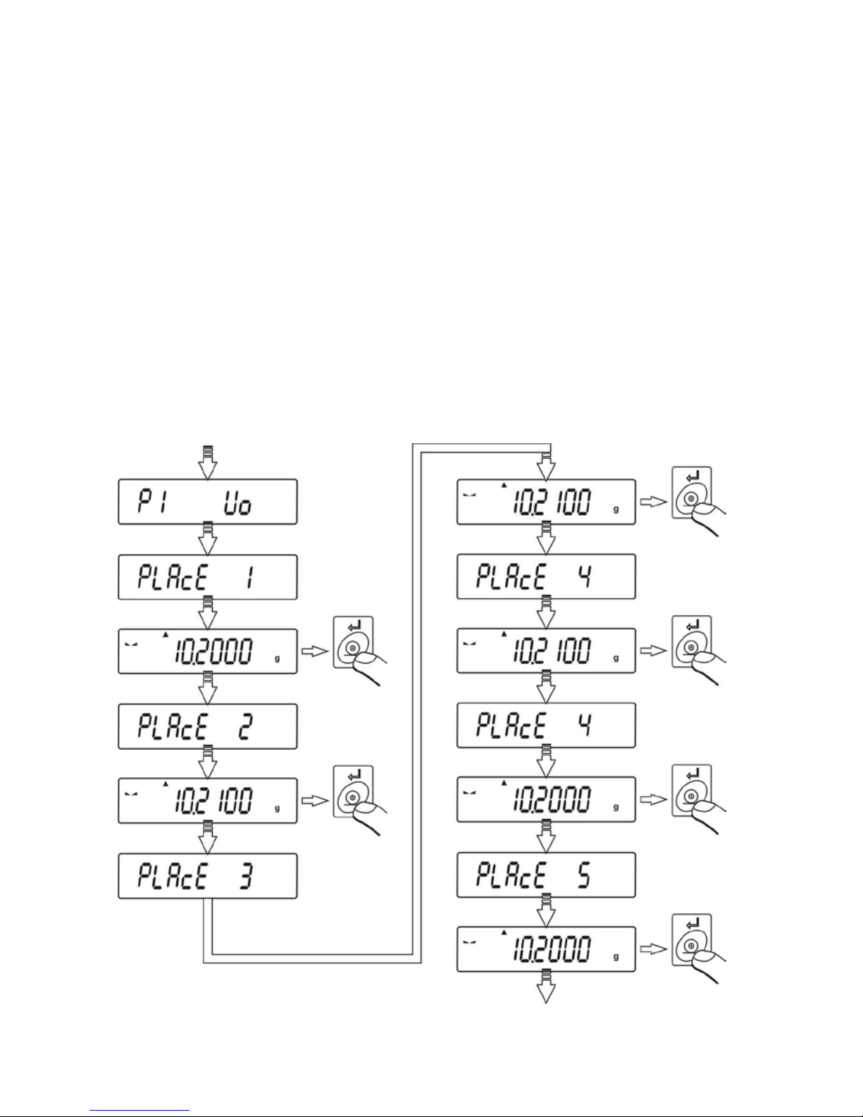
- 63 -
• Set h – set humidity of a weighing room in which pipettes calibration is
conducted (10 ÷ 95 %),
• V
0
– initial volume of a pipette (inserted by laboratory assistant),
• V
1/2
– 50% of pipette volume (inserted by laboratory assistant),
• V
1
– nominal volume of a pipette (inserted by laboratory assistant).
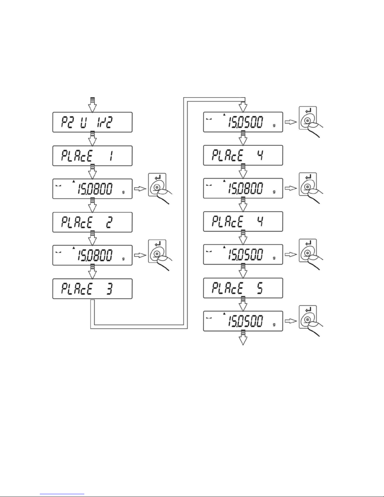
14.6.2. First measuring series
Insert data required for pipettes calibration process and press ESC/TARE key
(when balance displays stability pictogram) – balance will start the first series of
measurements P1 V
o
. Quantity of repetitions is conditioned by previously declared
value of Set n parameter.
Page 64
- 64 -
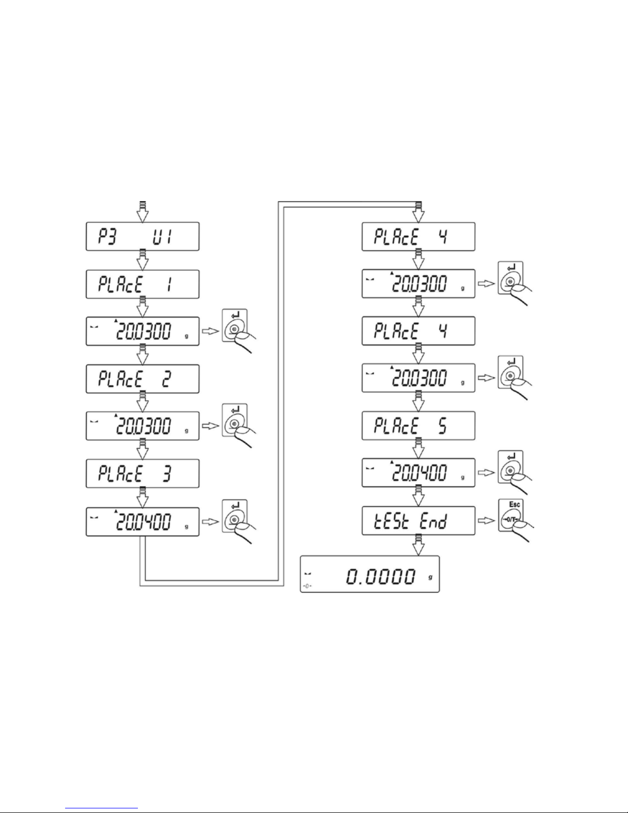
14.6.3. Second measuring series
The second series of measurements is a continuation of first one and procedure is
conducted as in case of the first one:
Page 65
- 65 -
14.6.4. Third measuring series
Third series of measurements is continuation of the second series (procedure does
not change). As the third series is completed, balance will display a message on
completion of calibration process (test End). Using RS 232 output balance will send
a report from pipettes calibration to a printer or computer connected to the output. In
order to finish the process of pipettes calibration, press ESC/TARE key.
Page 66
- 66 -
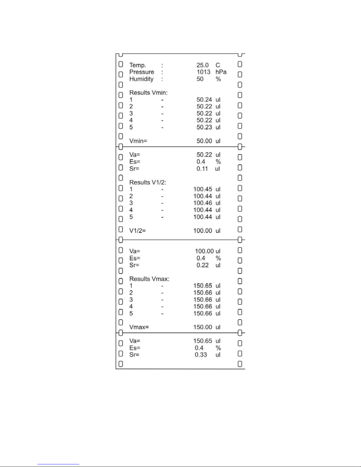
An example of a printout from pipettes calibration:
• V
min
, V
1/2
, V
max
– respectively: initial volume, 50% of pipette volume and
nominal pipette volume,
• V
a
– arithmetic mean from measurement series,
• E
s
– value of systematic error,
• S
r
– value of repeatability standard deviation.
Page 67

- 67 -
15. RS 232 FUNCTIONS
P4 Print
P4.1 bAud | 4800
P4.2 CntA | YES
P4.3 CntB | YES
P4.4 rEPl | YES
P4.5 PStb | YES
P4.6 Lo | 0.005
P4.1 bAud - baud rate setting (speed of transmission)
P4.2 CntA - continuous data transmission in basic measuring unit
P4.3 CntB - continuous data transmission in current measuring unit
P4.4 rEPl - setting operation mode for RS 232 output (manual / automatic)
P4.5 PStb - stable / unstable measurement for RS 232 transmission
P4.6 Lo - minimal mass required for activation of automatic printout
15.1. Baud rate
Page 68

- 68 -
Select required baud rate value
- 2400 bit/s
- 4800 bit/s
- 9600 bit/s
- 19200 bit/s.
Return to weighing mode with procedure of saving changes
(see point – 8.2. – return to weighing).
15.2. Continuous transmission
15.2.1. Continuous transmission in basic measuring unit
no – continuous transmission disabled
YES – continuous transmission enabled.
Return to weighing mode with procedure of saving changes
(see point – 8.2. – return to weighing).
Page 69

- 69 -
15.2.2. Continuous transmission in current measuring unit
no – continuous transmission disabled
YES – continuous transmission enabled.
Return to weighing mode with procedure of saving changes
(see point – 8.2. – return to weighing).
Page 70

- 70 -
15.3. Setting operation mode for RS 232 interface
no – manual operation (enabled on pressing PRINT key)
YES – automatic operation (enabled on stabilization of weighing
result).
Return to weighing mode with procedure of saving changes
(see point – 8.2. – return to weighing).
Automatic operation takes place according to the following scheme:
press Esc/TARE key to zero the balance (display will indicate
pictograms of stable measurement
and precise zero )
place the load, balance will send first stable measurement through the
RS232 interface
remove the weighed load from the weighing pan,
next measurement can be conducted if a weighing result equals +/- 50
reading units from zero (it is not necessary to reach precise zero to
start another measurement).
Page 71

- 71 -
15.4. Determination of data type sent via RS 232 output
no – sending stable or temporary (unstable) weighing result
YES – sending stable weighing result.
Return to weighing mode with procedure of saving changes
(see point – 8.2. – return to weighing).
Page 72

- 72 -
15.5. Minimum mass required for activating automatic printout
Balance software is equipped with a function for setting automatic operation.
While in automatic operation, data will not be transmitted through RS 232 to a
connected computer or printer until mass reading is above Lo value.
• Press F key to select a digit which should be changed, and press UNITS
key to change value of selected digit.
Return to weighing mode with procedure of saving changes
(see point – 8.2. – return to weighing).
Page 73

- 73 -
16. COOPERATION WITH A PRINTER OR A COMPUTER
CAUTION
A peripheral device that is connected to RS 3232 output of a balance, has
to be powered from the common low voltage power network equipped with
common anti-shock protection in a way to preclude possible occurrence of
different potentials in zero cables of the peripheral device and the balance.
Transmission parameters programmed in a balance:
- Baud rate - 2400 – 19200 bit / s
- Data bits - 8
- Stop bit - 1
- Parity control - none.
The value indicated on balance display can be sent through RS 232 output to a
peripheral device in one of four accessible ways:
• manually – on pressing PRINT key
• automatically – on stabilization of weighing result
• continuously – on activation of a function or sending a
command
• on command sent from a peripheral device (see additional functions).
Value indicated on balance’s display can be sent through RS232 output in the
following form:
• stable – data is sent immediately on stabilization of weighing
result
• unstable – on pressing of PRINT key causes immediate sending
of display status to a peripheral device (on a printout
such status is marked with <?> symbol proceeding the
weighing result).
Page 74
- 74 -
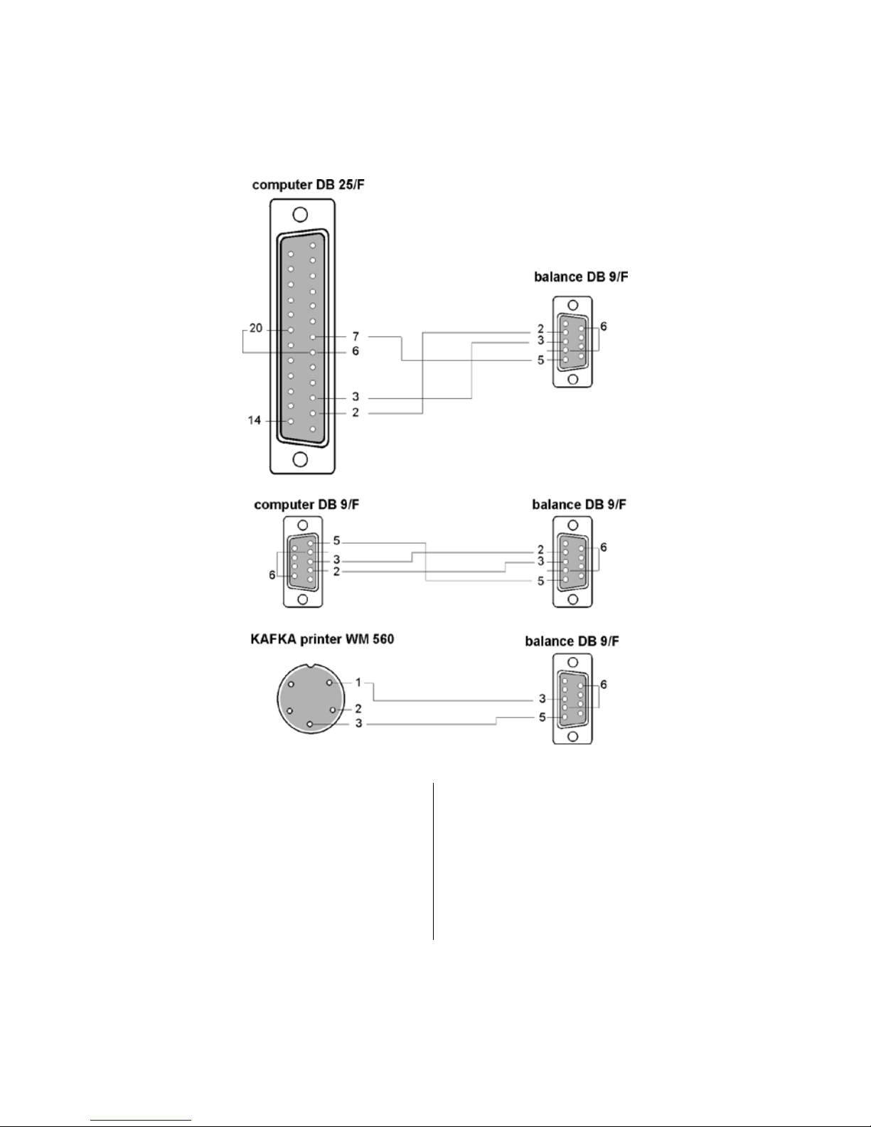
16.1. Cross-section through connecting conductors
BALANCE
COMPUTER
2 (RxD)
3 (TxD)
3 (TxD)
2 (RxD)
4 (DTR)
6 (DSR)
5 (GND)
5 (GND)
6 (DSR)
6 (DTR)
7 (RTS)
8 (CTS)
8 (CTS)
7 (RTS)
Page 75

- 75 -
16.2. Printing date with specified date and time
Every weighing result can be printed with specification of measurement date
and time. The presence of date and time on a printout is conditioned by
connection of printers type Kafka 1/Z or Kafka SQ S to a balance.
When connected, go to balance menu and set parameters from group P2 GL P:
PdAt - YES
Ptin - YES
16.3. Cooperation with statistic printer KAFKA SQS
On connecting a statistic printer KAFKA SQ S to a balance, it is possible to
carry out statistics from completed measurements. An instance of a printout
including statistics from series of measurement:
1 9:02:15 + 7.0016 g
2 9:02:39 + 5.0152 g
3 9:02:58 +
12.0171 g
4 9:03:15 + 9.9937 g
5 9:03:34 + 12.0169 g
6 9:03:48 + 22.0111 g
Date 13.09.2001 Time 9:04
n 6 batch quantity
sum x 68.0556 g total mass of samples
x
11.34260 g average value
s 5.92328 g standard deviation
srel 52.22 % variance f actor
min 5.0152 g min value
max 22.0111 g max value
R 16.9959 g difference max – min
16.4. Format of data sending
Weighing result can be sent to a peripheral device by pressing PRINT key on a
balance keyboard or by setting a control command from computer level.
Page 76
- 76 -
16.4.1. Format of data sent on pressing of PRINT key
Depending on setting of P4.5 PStb parameter only stable measurement or
instantaneous mass indication will be sent.
CAUTION:
For verified balances printout of instantaneous measurement data is
blocked.
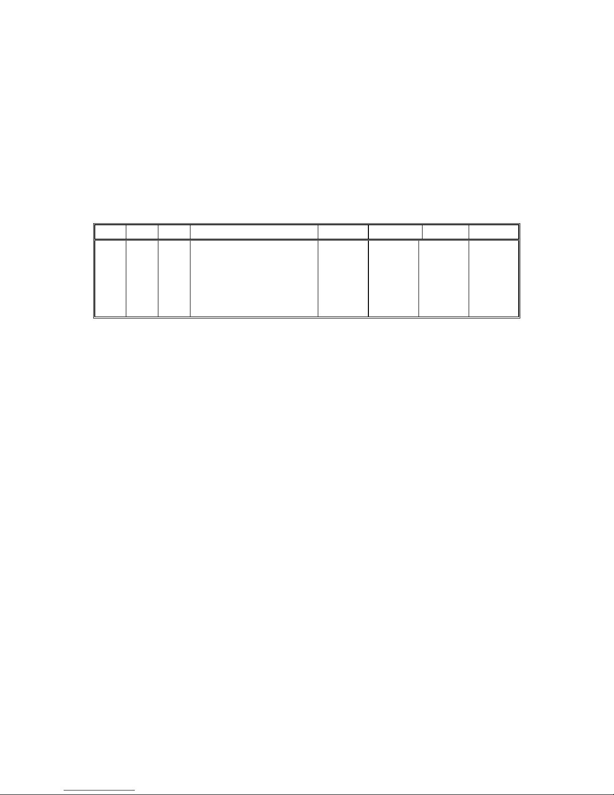
Printout format
1 2 3
4 - 12
13
14 - 16
17
18
stability
marker
space
sign
mass
space
unit
CR
LF
stability marker – [space] if stable
− [?] if unstable
− [^] if there is an error of range exceeding on +
− [v] if there is an error of range exceeding on -
sign – [space] for positive values or [-] for negative values
mass – 9 marks alignment to the right
unit – 3 marks alignment to the left
16.4.2. Format of data sending as response to commands
generated from a computer
On receipt of a command, balance responses with:
XX_A CR LF – command understood, in progress
XX_I CR LF – command understood, but currently not available
XX _ ^ CR LF – command understood, but max range is exceeded
XX _ v CR LF – command understood, but min range is exceeded
XX _ E CR LF – error occurred while carrying out the command – time
limit exceeded while waiting for stable measurement
result (time limit is characteristic parameter of balance)
XX – name of command
And followed by:
Page 77

- 77 -
1 – 3
4 5 6 7 8 – 16
17
18 - 20
21
22
Command
space
stability
marker
space
sign
mass
space
unit
CR
LF
Command – 1 ÷ 3 characters
stability marker – [space] if stable
– [?] if unstable
– [^] if there is an error of range exceeding on +
– [v] if there is an error of range exceeding on -
sign – [space] for positive values or [-] for negative
values
mass – 9 marks alignment to the right
unit – 3 marks alignment to the left
Page 78

- 78 -
17. UNDER HOOK WEIGHING
In standard analytical and precision balances loads can be weighed under the
weighing pan. Such means of operation requires placing a balance on a uplifted
position. RADWAG offers a rack for under hook weighing. The rack is an optional
equipment offered for balances AS series.
For under hook weighing follow below procedure:
• Remove plastic hole plug in basis of a balance;
• There is suspension place for hook visible in the hole – the suspension is
installed permanently to balance mechanism;
• In the hole install the hook for under hook weighing - the hook is standard
equipment of a balance. Weigh loads using under hook option;
• As under hook weighing is finished, close the hole in balance basis with
plastic hole plug.
CAUTION:
The suspension for hook must not be turned, twisted or manipulated
in any direction. Such actions may cause damage to balance
mechanism.
Mass of all additional elements of under hook weighing kit, like: the hook,
weighing pan, string, etc. should be zeroed by pressing Esc/TARE key.
Page 79

- 79 -
18. LIST OF COMMANDS: COMPUTER – BALANCE
• Function TARE
Command T CR LF (balance tarring)
• Function ZERO
Command Z CR LF (balance zeroing)
• Function IMMEDIATELY SEND WEIGHING RESULT IN BASIC
MEASURING U NIT
Command SI CR LF (immediately send of balance indication)
• Function SEND WEIGHING RESULT IN BASIC MEASURING
UNIT
Command S CR LF (send result when stable)
• Function SEND W E IGHING RESULT IN CURRENT MEASURING
UNIT
Command SU CR LF (send result with current unit when stable)
• Function IMMEDIATELY SEND WEIGHING RESULT IN
CURRENT MEASURING UNIT
Command SUI CR LF (send result in current unit now – do not wait
for stable reading)
• Function CONTINUOUS T RANSMISSION IN BASIC
MEASURING U NIT
Command C1 CR LF (start continuous transmission in basic unit)
• Function END OF CONTINUOUS TRANSMISSION IN BASIC
MEASURING U NIT
Command C0 CR LF (finish continuous transmission in basic unit)
• Function CONTINUOUS T RANSMISSION IN CURRENT
MEASURING U NIT
Command CU1 CR LF (start continuous transmission in current
unit)
• Function END OF CONTINUOUS TRANSMISSION IN BASIC
MEASURING U NIT
Command CU0 CR LF (finish continuous transmission in current
unit)
Page 80

- 80 -
CAUTION
If a non-existing or incorrect command finished with CR LF will be sent
to a balance, it responses with ES CR LF. Space between characters
should be omitted, as they are added only for the purpose of proper
legibility.
19. ERROR MESSAGES
Er1 Hi – mass out of range on balance start and adjustment
Er2 nuLL – value from AD converter ≤ 0 (A/D ≤ 0)
Er3 FuL1 – values from A/D converter ≥ maximal converter range (A/D ≥ 0)
Er4 FuL2 – maximal capacity of the balance exceeded (over load)
Er5 rout – mass value out of range (during adjustment, determining
reference for sample quantity and percent setup, etc.),
Er7 tout – timeout error for zeroing and tarring
Er8 outr – enter value (from keyboard level) out of range (setting thresholds /
limits values)
Er9 Lock – function blocked (e.g. by LFT),
Er10 cal – adjustment error (change of mass or incorrect mass of adjustment
weight / mass standard).
Page 81

- 81 -
20. ADDITIONAL EQUIPMENT
20.1. Anti-vibration table
It is a very stable basis which eliminates all kinds of vibrations
and ground shakes. The inner part of the table holds a marble
plate, which is a foundation for balance positioning.
20.2. Rack for under hook weighing
The rack is used if under hook weighing option has to be
applied. Under hook weighing is necessary if magnetic loads
are weighed or during density determination of substances.
Racks are also used for measuring absorptiveness of
substances e.g. foamed polystyrene. The rack is made of mild
steel. Rack height is 330mm.
20.3. Density determination kit (for solids and liquids)
It is applicable with balance with resolution at least 1 mg.
Designed for density determination of solids and liquids. The
procedure is fully automatic, i.e. the user only places
samples on kit’s weighing pans.
20.4. Additional display
Features: Length of conductor between additional display and
balance – 1,5m, plastic casing, possibility of tilting the
additional display head.
Page 82

- 82 -
20.5. Computer software
PW-WIN 2004 - gathering data. Data is gathered in tabiular or chart
format. It is possible to calculate statistics from a series of weighing
records.
RAD-KEY 2000 – implements a set of commands for controlling a
balance, e.g. tarring, start of continuous transmission, cyclic
commands set to a balance.
REC-FS 2000 - application for control of formulas. It enables
creation of a formula, declare tolerance limits for each ingredient
and measure mass of each ingredient of a formula.
Number of instruction:
LMI-16-09/05/12/A
Page 83

 Loading...