

Page 1
User Manual
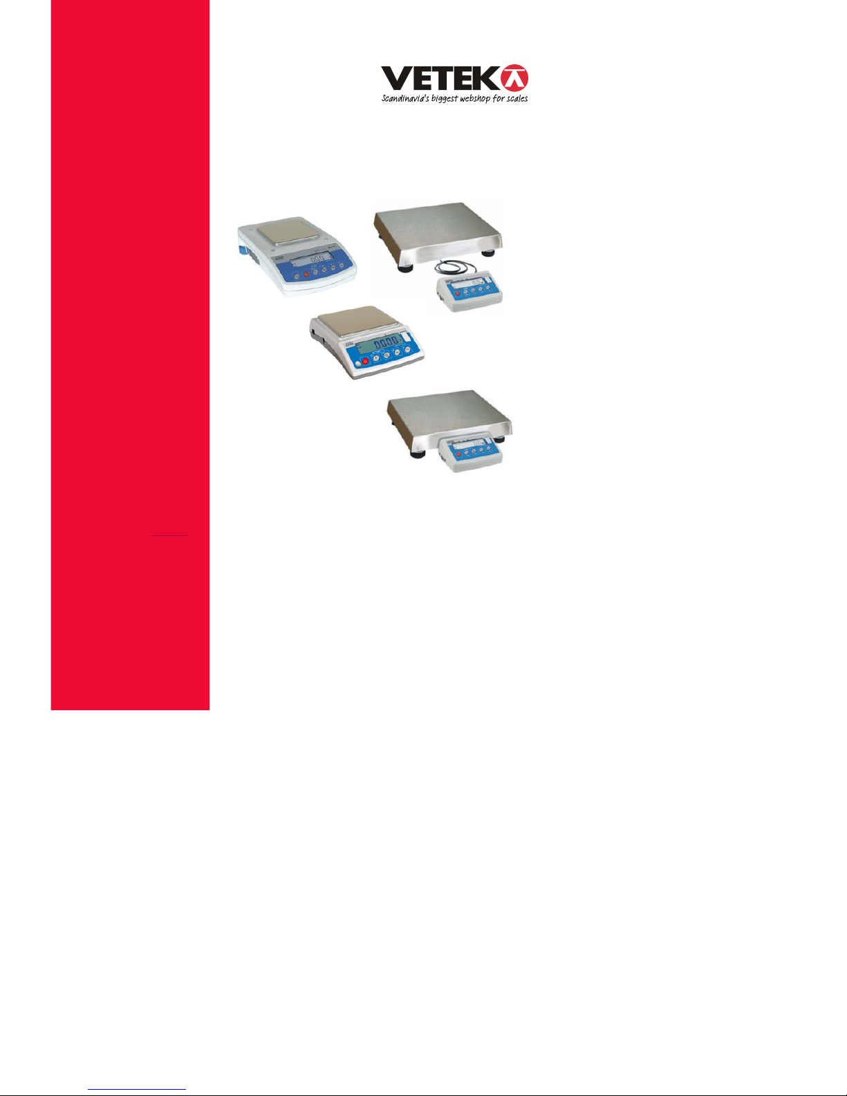
Precision scales – WLC series
Manual number:
LTI-05-11/01/09/A
Vetek Weighing AB, Box 79, S-76040 Väddö, Sweden
Phone
+46 176 20 89 20 fax. +46 176 20 89 29
.vetek.com
Page 2

- 2 -
JANUARY 2009
Page 3

- 3 -
TABLE OF CONTENTS
1. INTENDET USE..................................................................................................................... 5
2. PRECAUTIONS..................................................................................................................... 6
2.1. Maintenance .................................................................................................................. 6
2.2. Power supply ................................................................................................................. 6
3. WARRANTY CONDITIONS................................................................................................... 6
4. MAIN DIMENSIONS .............................................................................................................. 7
5. UNPACKING AND ASSEMBLY............................................................................................ 9
6. GETTING STARTED ........................................................................................................... 10
7. BALANCE LEVELLING ...................................................................................................... 11
8. KEYPAD.............................................................................................................................. 11
9. EYS’ FUNCTIONS ............................................................................................................ 12K
10.
INSCRIPTIONS ON THE DISPLAY .................................................................................. 13
11. USER MENU ..................................................................................................................... 14
11.1. Submenus ................................................................................................................. 14
11.2. Brows ng user menu .................................................................................................. 15i
11.2.1.
pad ............................................................................................................ 15Key
11.2.2.
Return to the weighing mode .......................................................................... 15
12. WEIGHING ........................................................................................................................ 16
12.1. Tarring ....................................................................................................................... 17
12.2. Inscribing tare value .................................................................................................. 17
12.3. Zeroing ...................................................................................................................... 18
12.4. Weighings in two ranges ........................................................................................... 18
12.5. Selection of basic weight unit .................................................................................... 19
1
13.
MAIN PARAMETERS........................................................................................................ 21
2.6. Temporarily selected unit .......................................................................................... 20
13.1. Setting a filtering level ............................................................................................... 21
13.2. Median filter ............................................................................................................... 22
13.3. Autozero function....................................................................................................... 23
1
14.
RS 232 PARAMETERS..................................................................................................... 25
3.4. Tare function.............................................................................................................. 24
14.1. Printout type............................................................................................................... 25
14.2. Minimal mass threshold............................................................................................. 26
14.3. Baud rate ................................................................................................................... 27
1
15.
OTHER PARAMETERS .................................................................................................... 29
4.4. Serial transmission parameters ................................................................................. 28
15.1. Backlight function ...................................................................................................... 29
15.1.1. ing from mains.................................................................. 29Backlight for supply
15.1.2.
Backlight for supplying from batteries ............................................................. 30
15.2. “Beep” signal – after pressing a key .......................................................................... 31
15.3. Automatic switch-off .................................................................................................. 31
15.4. Batter voltage level check........................................................................................ 32y
15.4.1.
..................................................................................... 32Checking the batteries
15.4.2.
discharge pictogram............................................................................ 33Battery
15.4.3.
........................................................................... 33Accumulator charging option
15.4.4.
Formatting rechargeable battery packs........................................................... 34
16. OPERATION MODES........................................................................................................ 35
16.1. Setting accessibility of operation modes ................................................................... 35
16.2. Selecting quantity of operation modes ...................................................................... 36
16.3. Counting pieces of the same mass ........................................................................... 37
16.4. +/- control referring to the inscribed standard mass .................................................. 39
16.5. Control of % deviation referring to the inscribed standard mass ............................... 40
Page 4

- 4 -
16.5.1. its weighing..................................................... 41Standard mass determined by
16.5.2.
Mass of standard inscribed to scale memory .................................................. 42
16.6. Automatic tare ........................................................................................................... 43
16.7. Measurement of maximal force on the pan – latch.................................................... 44
16.8. Totalizing ................................................................................................................... 44
16.8.1. ork mode.................................................................................. 45Enabling the w
16.8.2.
........................................................................................ 45Totalizing procedure
16.8.3.
of the last value of sum of weighed goods ........................................ 46Memory
16.8.4.
Return to weighing .......................................................................................... 47
16.9. eighing animals ...................................................................................................... 48W
16.10.
Tare memory............................................................................................................ 49
16.10.1. Entering the tare value to the scale memory ................................................. 49
16.10.2. Selecting a tare value from the memory........................................................ 51
17. SCA E CALIBRATION ..................................................................................................... 52L
17.1.
Internal calibration ..................................................................................................... 52
17.1.1. .............................................................................. 53Manual internal calibration
17.1.2.
Automatic internal calibration .......................................................................... 54
17.2. External calibration .................................................................................................... 57
1
18.
COOPERATION WITH PRINTER ..................................................................................... 60
7.3. Start mass adjustment............................................................................................... 58
19. COOPERATION WITH COMPUTER................................................................................. 61
20. COMMUNICATION PROTOCOL ...................................................................................... 62
20.1. General information ................................................................................................... 62
20.2. A set of commands for RS interfaces ........................................................................ 62
20.3. Respond message format ......................................................................................... 63
20.4. Command’s description ............................................................................................. 63
20.4.1. ng ............................................................................................................ 63Zeroi
20.4.2.
ng ............................................................................................................. 63Tarri
20.4.3.
.................................................................. 64Send the stable result in basic unit
20.4.4.
in basic unit ........................................................ 64Send the result immediately
20.4.5.
............................................................... 65Send the stable result in current unit
20.4.6.
in current unit ..................................................... 65Send the result immediately
20.4.7.
itch on continuous transmission in basic unit ............................................. 66Sw
20.4.8.
itch off continuous transmission in basic unit ............................................. 66Sw
20.4.9.
Switch on continuous transmission in current unit .......................................... 67
20.4.10. Switch off continuous transmission in current unit ........................................ 67
20.4.11. Send all implemented commands ................................................................. 67
20.5. Manual printouts / automatic printouts....................................................................... 68
20.6. Continuous transmission ........................................................................................... 69
2
21.
ERROR COMMANDS........................................................................................................ 70
0.7. Configuring printouts ................................................................................................. 69
22. TROUBLE SHOOTING ..................................................................................................... 70
23. TECHNICAL PARAMETERS ............................................................................................ 71
23.1. Precisions scales of WLC series ............................................................................... 71
23.2. Verified precise scales of WLC series ....................................................................... 72
23.3. Precise scales of WLC…/C/2 series.......................................................................... 73
2
24.
ADDITIONAL EQUIPMENT............................................................................................... 74
3.4. Verified precise scales of WLC…/C/2 series............................................................. 73
Page 5

- 5 -
1. INTENDET USE
Scales are designed for fast and precise measurements of weighed loads
masses and direct commercial settlements. Tarring in full weighing range
enables to determine net mass of weighed loads. Additional display is
additional equipment of scale.
Functions:
x backlight of display
x level of filtration
x autozero function
x setting baud rate of transmission
x continuous data transmission for RS 232
x automatic operation for RS 232
x designed printouts
x designation minimum mass for function operating
x counting pieces
x +/- mass control
x percentage deviation from standard mass
x latch of maximum scale indication
x automatic tare
x memory of tare
x inscribing tare value
x Memory of 9 tare values
x automatic scale switch-off
x user calibration
x internal calibration
x Totalizing
x Weighing animals
User functions may have attribute of accessibility. For this reason it is
possible to adjust scale to individual needs to provide access to only
these functions which are currently needed. Attribute determination
accessible / inaccessible is possible in user menu and described in
further part of manual.
Page 6
2. PRECAUTIONS
2.1. Maintenance
A. Please, read carefully this user manual before and use the device
according to its intended use.
B. Dead batteries (accumulators) should be utilized according to the law;
C. Devices that are to be withdrawn from use age should be sent back to
the producer or in case of own utilization do it according to the law.
In case of an elongated storage period in low
temperatures, it is not allowed the full discharge
of the accompanied batteries.
2.2. Power supply
Weighing indicators in plastic casing and WLC/B1 series can be supplied
from power adapters and NiMH rechargeable batteries (standard
equipment). New rechargeable batteries should be formatted according
to the description in the chapter 15.4.4. of this manual.
If you want to use normal batteries instead of rechargeable ones,
proceed as follows:
x Before installing non-rechargeable batteries turn on the device
and set <5.5.CHr6> to <no>, to switch off charging.
x Then install the batteries.
Installing batteries without changing <5.5.CHr6> to <no>
may cause damage of batteries and the indicator.
3. WARRANTY CONDITIONS
A. RADWAG is obliged to repair or change those elements that
appears to be faulty because of production and construction reason,
B. Defining defects of unclear origin and outlining methods of
elimination can be settled only in participation of a user and the
manufacturer representatives,
C. RADWAG does not take any responsibility connected with
destructions or losses derives from non-authorized or inappropriate
(not adequate to manuals) production or service procedures,
- 6 -
Page 7
D. Warranty does not cover:
x Mechanical failures caused by inappropriate maintenance of
the device or failures of thermal or chemical origin or caused
by atmospheric discharge, over voltage in mains or other
random event,
x Inappropriate cleaning.
E. Loss of warranty appears after:
x Access by an unauthorized service,
x Intrusion into mechanical or electronic construction of,
unauthorized people,
x Removing or destroying protection stickers.
F. Warranty conditions outline the warranty period for rechargeable
batteries attached to the device for 12 months.
G. The detailed warranty conditions one can find in warranty certificate.
H. Contact with the central authorized service:
+48 48 384 88 00 ext. 106 or 107.
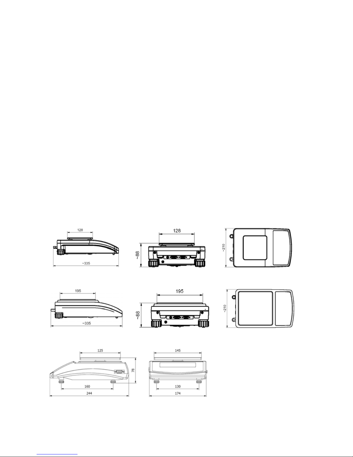
4. MAIN DIMENSIONS
Scales WLC/A1/C/2
Scales WLC/A2, WLC/A2/C/2
Scales WLC/B1
- 7 -
Page 8
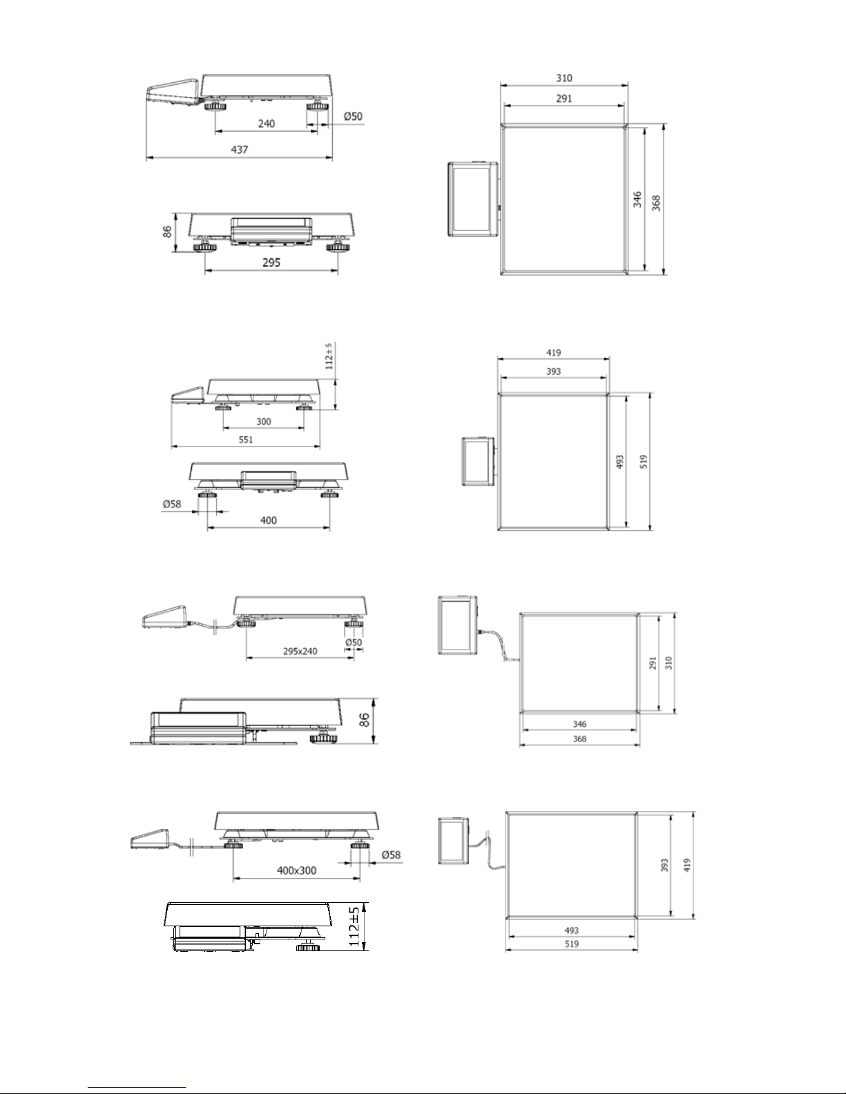
Scales WLC/C1/R
Scales WLC/C2/R
Scales WLC/C1/K
Scales WLC/C2/K
- 8 -
Page 9
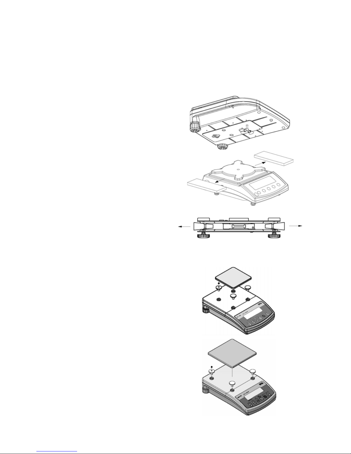
5. UNPACKING AND ASSEMBLY
x Unpack and put the scale on a flat even stable surface far away
from sources of heat,
x Remove the transport protection:
Scales WLC…/C/2:
Scales WLC/B1:
Scales WLC/C/K, WLC/C/R:
x Install the weight pan according to the drawings below:
Scales WLC/A1/C/2:
scales WLC/A2, WLC/A2/C/2:
- 9 -
Page 10
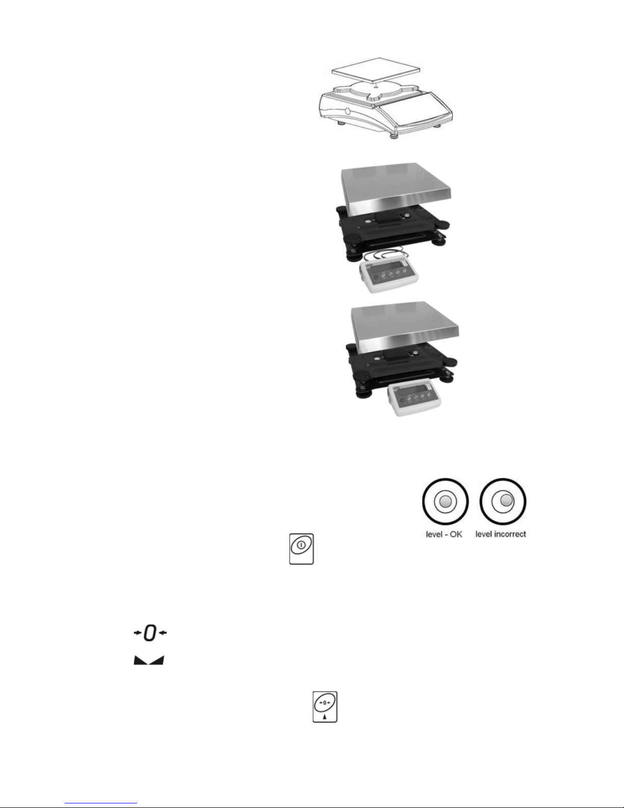
scales WLC/B1:
scales WLC/C/K:
scales WLC/C/R:
6. GETTING STARTED
x After unpacking and mounting the scale level it
out. Use levelling legs and the level condition
indicator installed in the basis of the scale.
x Turn the device on using the key – keep pressing the key
for about 0.5 sec,
x Wait for the test completion,
x Then you will see zero indication and pictograms:
- zero indication
- stable result
kg - weight unit
x If the indication is not zero press
key.
- 10 -
Page 11
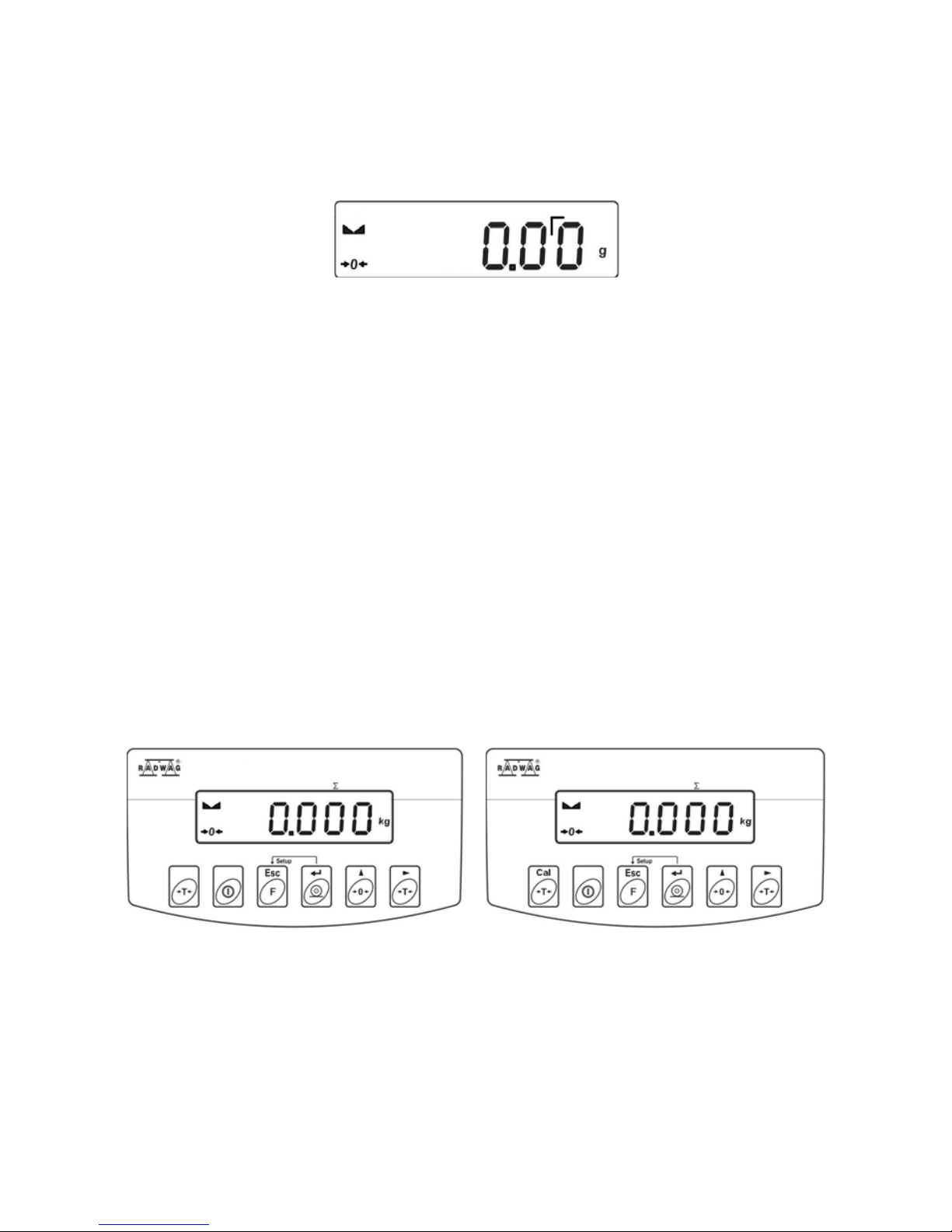
Caution:
In case of verified scales in II OIML class with divisions e=10d
(where: d – reading division, e – verified division) the last digit
will be marked as shown below:
7. BALANCE LEVELLING
x Operation temperature range for this device is outlined as
+15qC y +30qC;
x After powering up this device requires 30 minute worming up;
x During the worm-up time the indication can change;
x User calibration should be performed after the warm-up time.
x Temperature and humidity changes during operation can increase
measurement errors, which can be minimized by performing the
user calibration process.
8. KEYPAD
Keypad of WLC/A2 series Keypad of WLC…/C/2 series
- 11 -
Page 12
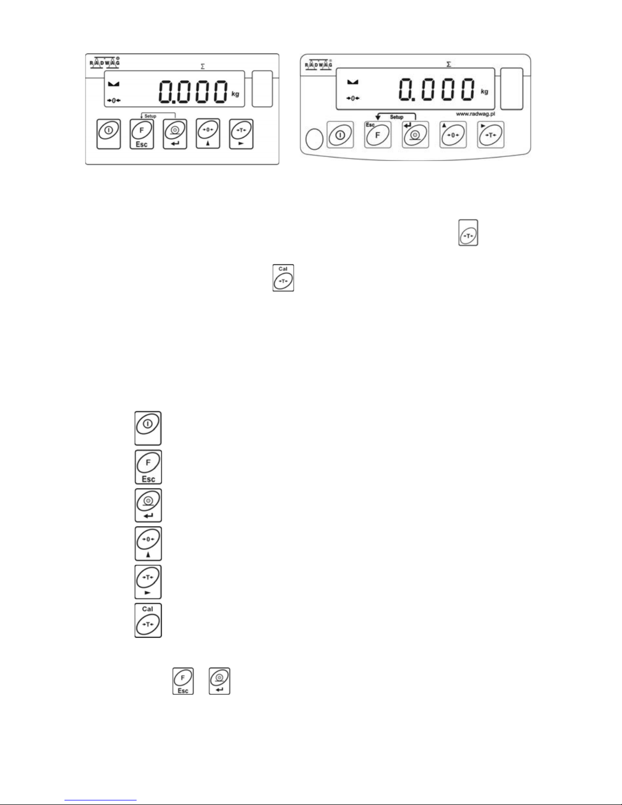
Keypad of WLC C1…C2 series Keypad of WLC/B1 series
Notice:
Scales of WLC/A2 series are equipped with an additional key
for
tarring and has no additional functions but the keypad of the WLC…/C/2
scale include an additional key
for direct starting the process of
internal calibration. Because the functionality and operation of the
rest of the keys is the same, the further part of this manual
describes the keypad of WLC C1…C2 series.
9. KEYS’ FUNCTIONS
Switching on/off
Function key (operation mode selection)
Sending a weighing result to RS232
Zeroing
Tarring
Manual internal calibration (WLC…/C/2 scales)
Notice:
After pressing
+ keys’ functions changes. The way of operation
in this mode is described in details further in this manual.
- 12 -
Page 13
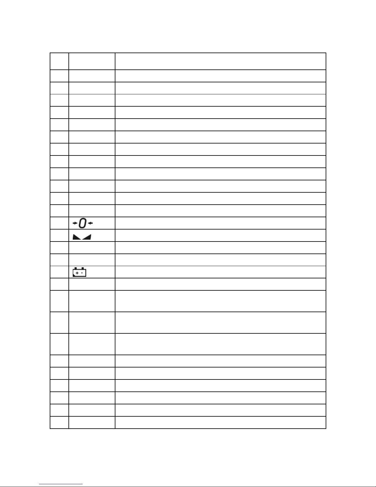
10. INSCRIPTIONS ON THE DISPLAY
No Text string Description
1 FIL
Filter level
2 bAud
Transmission baud rate
3 PCS
Piece counting
4 HiLo
+/- control according to a standard mass
5 rEPL
Automatic printout
6 StAb
The condition of printing data
7 Auto
Autozero correction
8 t1
Power save – time to switch off while no operation
9 toP
Latch of the max measurement
10 Add
Totalizing
11 AnLS
Weighing animals
12 tArE
Memory of 9 tare values
13
Indication in autozero zone (indication = exact zero)
14
Stable result (ready to read)
15 PCS
Operation mode - counting pieces
16 kg (g)
Operation mode - weighing
17
Rechargeable battery pack or battery discharged (BAT-LO)
18 Net
Tare function has been used
19 Min
+/- control with reference to the standard mass: setting
the lower threshold or mass below the first threshold
20 OK
+/- control with reference to the standard mass:
load mass between the thresholds
21 Max
+/- control with reference to the standard mass: setting
the upper threshold or mass over the second threshold
22 CALIb
The stability test for the internal calibration procedure
23 CAL-H
Manual internal calibration
24 CAL-A
Automatic internal calibration after powering up
25 CAL-t
Internal calibration triggered of by temperature
26 CAL-C
Internal calibration triggered of by timer
27 Abort
Terminating of internal calibration
- 13 -
Page 14

- 14 -
11. USER MENU
11.1. Submenus
User’s menu is divided into 6 basic submenus. Each group has its
own characteristic name preceded by the letter P and a number.
P1 rEAd
P 1.1 Fil |
3
P 1.2 Auto | YES
P 1.3 tArA | no
P 1.4 Fnnd | YES
P2 Prnt
P2.1 Pr_n | StAb
P2.2 S_Lo |
P2.3 bAud | 9600
P2.4 S_rS | 8d1SnP
P3 Unit
P3.1 StUn | kg
P4 Func
P4.1 FFun | ALL
P4.2 Funi | no
P4.3 PcS |
no
P4.4 HiLo |
no
P4.5 PrcA |
no
P4.6 Prcb |
no
P4.7 AtAr |
no
P4.8 toP |
no
P4.9 Add |
no
P4.A AnLS |
no
P4.b tArE |
no
P5 othr
P5.1 bL
|
Auto
P5.2 bLbt
|
70
P5.3 bEEP
|
YES
P5.4 t1
|
Auto
P5.5 CHr6
|
YES
P6 CAL
P6.1 St_u | * FUNCTION *
P6.2 uCAL | * FUNCTION *
P6.3 CA-C | 0
P6.4 CA-r | YES
Page 15
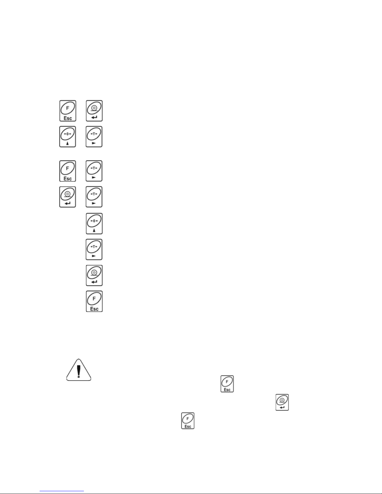
11.2. Browsing user menu
Use scale’s keys to move inside the menu.
11.2.1. Keypad
+
Entering main menu
+
Inscribing tare value
Increasing a digit value by „1”
moving down in the menu
+
Battery / accumulator state monitoring
+
Toggling between gross / net values
Selecting the parameter or changing the value
of a selected parameter
Entering the selected submenu
or activating a parameter for changes
Confirmation (enter)
Leaving without changes or reaching a higher level
of the menu
11.2.2. Return to the weighing mode
The changes that have been introduced should be saved
in order to keep them in the memory for good.
While leaving parameters press key until the text
<SAuE?> appears on the display. Then press:
– to save changes or – to leave without changes.
- 15 -
Page 16
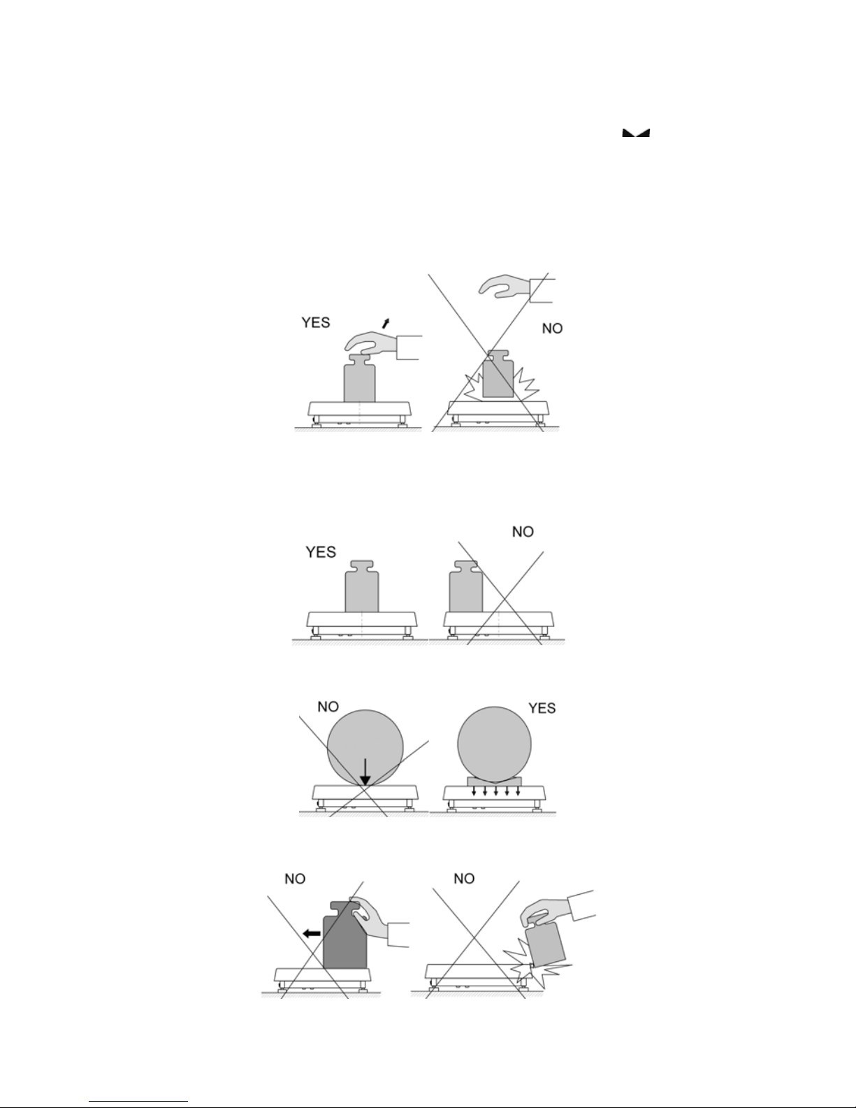
12. WEIGHING
Put a load you want to weigh on the weighing pan. When the
pictogram appears it means that the result is stable and ready to read.
In order to assure long-term operation and appropriate measurements of
weighted loads following precautions should be taken into consideration:
x Loads should be placed on the pan delicately and carefully
in order to avoid mechanical shocks:
x Loads should be placed centrally on the pan (errors caused
by eccentric weighing are outlined by standard PN-EN 45501
ch. 3.5 and 3.6.2):
x Do not load the pan with concentrated force:
x Avoid side loads, particularly side shocks should be avoided
- 16 -
Page 17
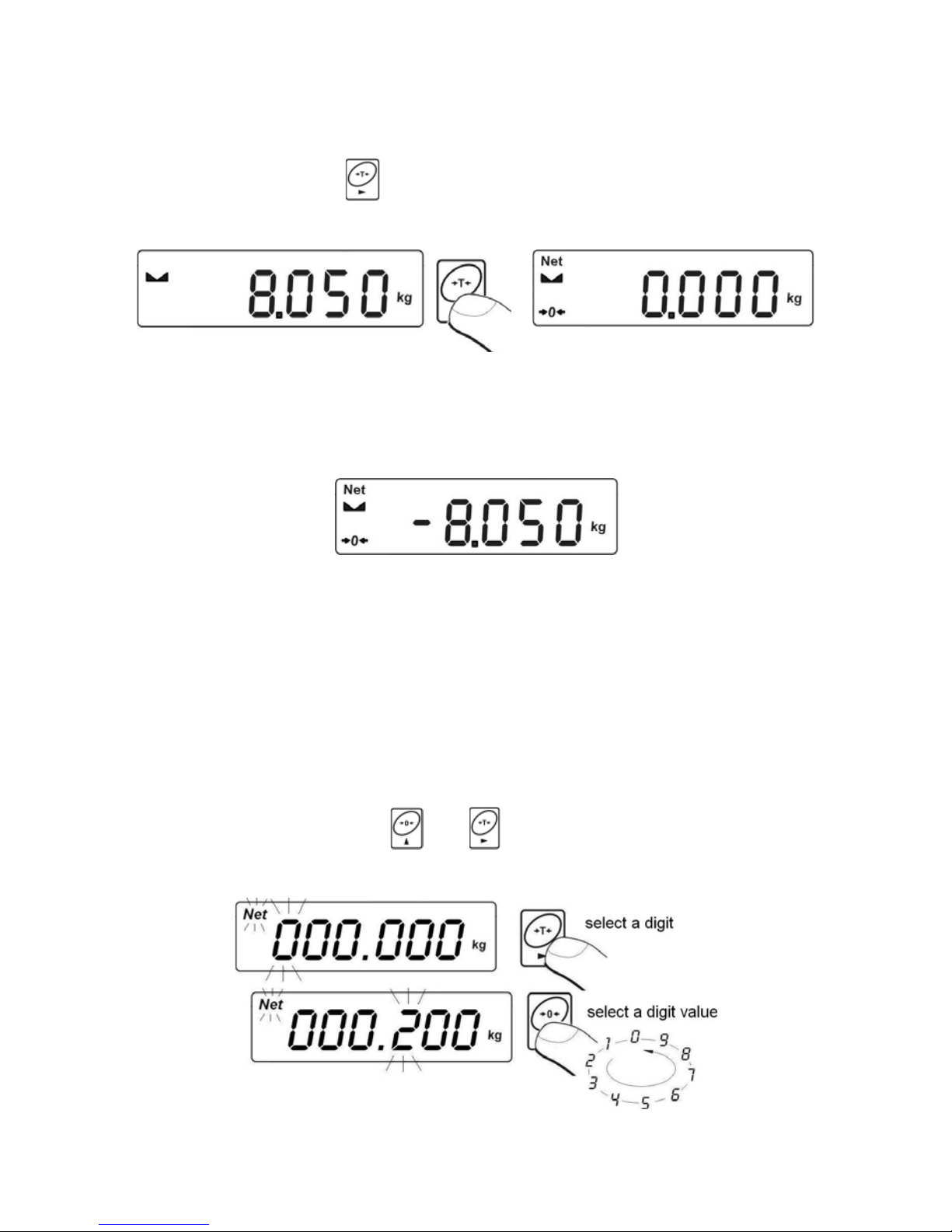
12.1. Tarring
In order to determine the net mass put the packaging on the pan.
After stabilising press -
(Net pictogram will be displayed in the
left upper corner and zero will be indicated).
After placing a load on the weight pan net mass will be shown.
Tarring is possible within the whole range of the scale. After unloading
the pan the display shows the tarred value with minus sign.
Notice:
Tarring cannot be performer when a negative or zero value is being
displayed. In such case Err3 appears on the display and short audible
signal will be emitted.
12.2. Inscribing tare value
You can also inscribe a tare value. While in weighings mode press:
x Press simultaneously
and ,
x You will see :
- 17 -
Page 18

x Using
and set the tare value,
x Press
,
x Program returns to weighings mode. The inscribed tare value
can be seen on the display with „–” sign,
x Tare can be inscribed anytime in weighings mode.
Notice:
1. You cannot inscribe a new tare value when the tare value in memory
is greater than zero. In the case of trying this the <Err3> message
will be displayed and short audible signal will be emitted.
2. Users can also enter up to 9 tare values to the scale memory
(see 16.10 of his manual).
12.3. Zeroing
To ZERO the scale press:
.
The scale will display zero and following pictograms:
and .
Zeroing is only possible within the scope of ±2% of full scale. While
zeroing outside the scope of ±2% you will see <Err2>. Zeroing
is possible only in stable state.
Notice:
Zeroing is possible only within the ±2% interval of the maximal range.
If zeroing is performed beyond this range the <Err2> message and
short audible signal will be emitted.
12.4. Weighings in two ranges
Switching between the I range and the II range happens automatically
(exceeding Max of the I range). Weighings in the second range is
signalled by a pictogram in the top left corner of the display.
Then weighings is done with the accuracy of the II range to the moment
of returning to zero (autozero range
) where the scale switches back
to the I range.
- 18 -
Page 19
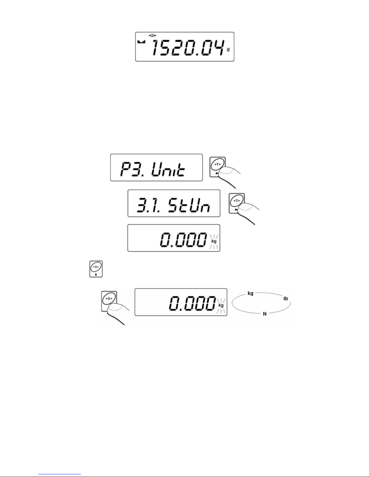
12.5. Selection of basic weight unit
This function is used to set weight unit the scale will start with.
Procedure:
x Enter the submenu <P3.Unit> and then:
x press , until the expected unit appears on the display:
Options:
A. When the basic unit is [kg], users can toggle between:
[kg, lb, N], for verified scales [lb] is not accessible,
B. If the basic unit is [g], users can toggle between:
[g, ct, lb], for verified scales [lb] is not accessible,
- 19 -
Page 20
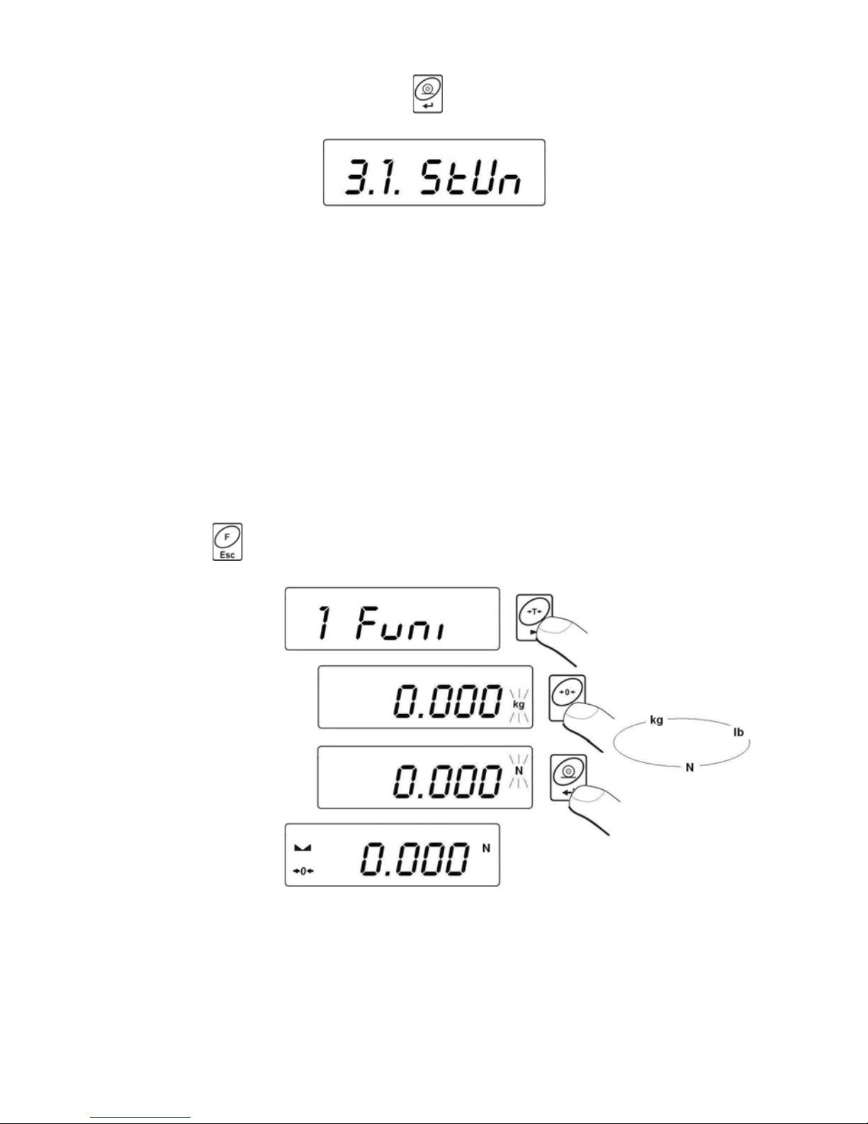
x After you select the unit press
, the scale returns to:
x Return to weighing according to chapter - 11.2.2.
Notice:
After turning on the scale always sets the basic unit.
12.6. Temporarily selected unit
This function is used to set weight unit the scale will use temporarily
until the next power off or next selection.
Procedure:
x Press
and then:
x After you select the unit you want come back to weighing procedure.
- 20 -
Page 21
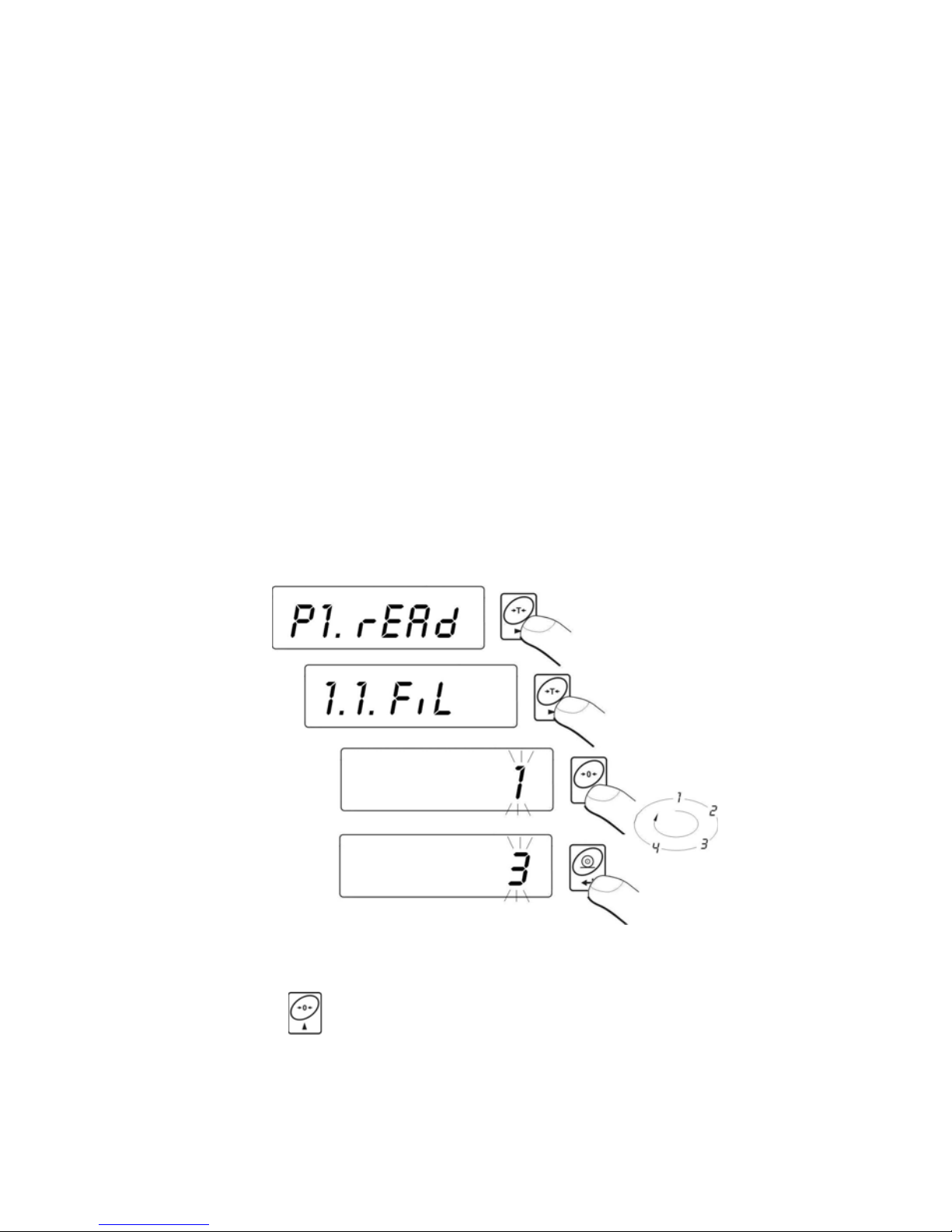
Options:
A. When [kg] is a basic unit, users can select following units:
[kg, lb, N], [lb] is not accessible for verified scales.
B. When [g] is a basic unit, users can select following units:
[g, ct, lb], [lb] is not accessible for verified scales.
13. MAIN PARAMETERS
Users can adjust the scale to external ambient conditions (filtering level)
or particular needs (autozero operation, tare memory). This parameters
are placed in <P1.rEAd> submenu.
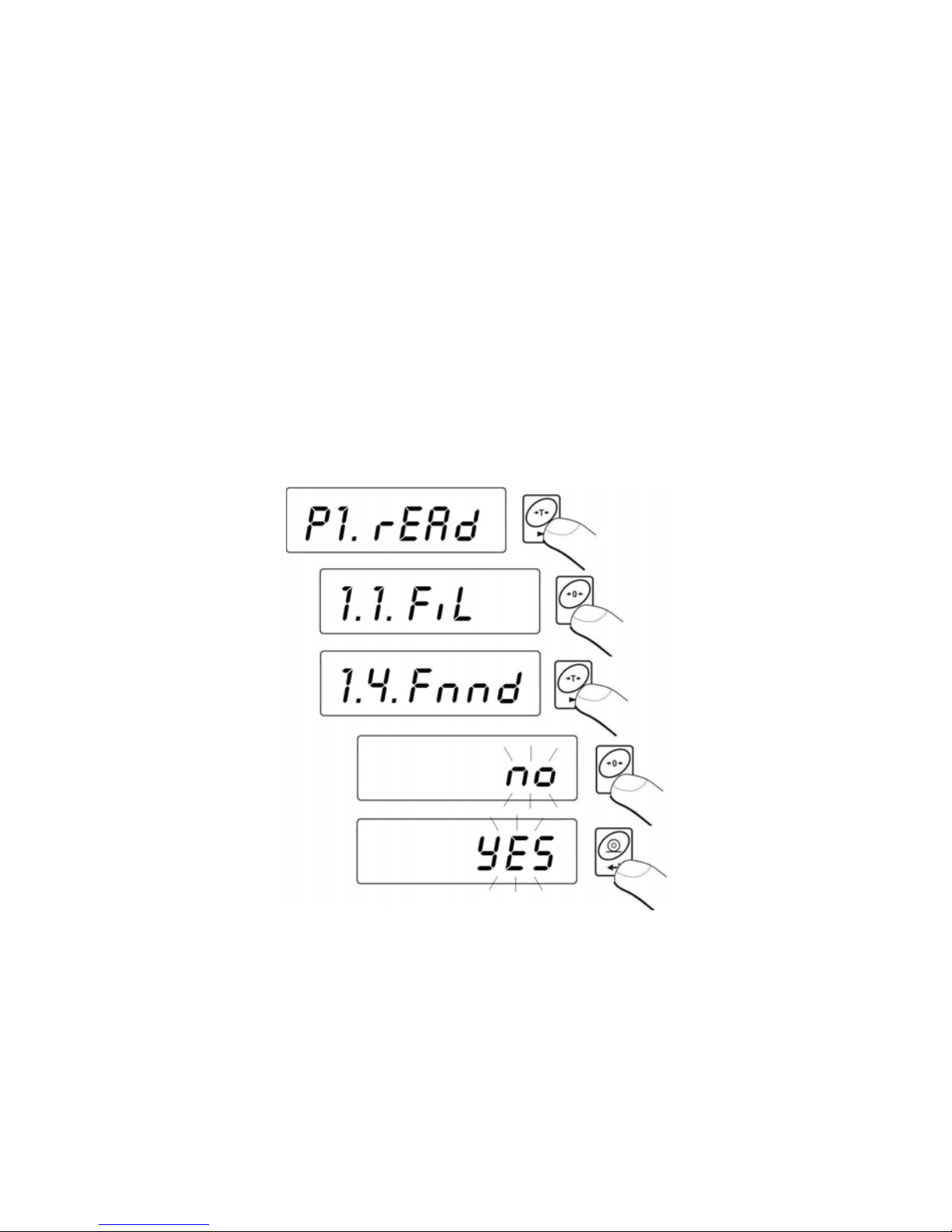
13.1. Setting a filtering level
Procedure:
x Enter the submenu <P1.rEAd> and then:
1 - 4 - level of filtering
x By pressing
select the filtering level you need
- 21 -
Page 22
Notice:
Filtering level influences the time of stabilization. The higher the filtering
level is the longer stabilization time is needed.
Return to weighing:
See - 11.2.2.
13.2. Median filter
This filter eliminates short changes (impulses) of measure signal
(e.g. shocks).
Procedure:
x Enter the submenu <P1.rEAd> and then:
Fnnd no - filter disabled
Fnnd YES - filter enabled
Return to weighing:
See - 11.2.2.
- 22 -
Page 23
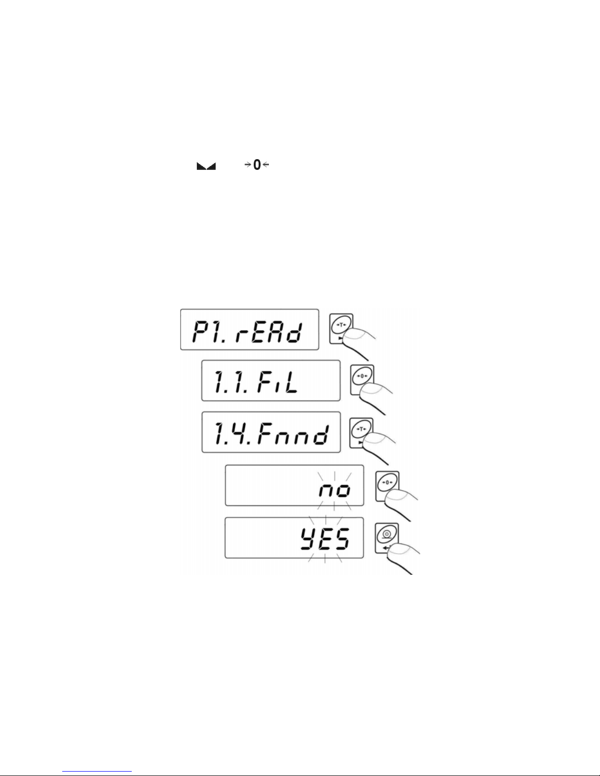
13.3. Autozero function
The autozero function has been implemented in order to assure precise
indications. This function controls and corrects „0” indication. While the
function is active it compares the results continuously with constant
frequency. If two sequentional results differ less than the declared
value of autozero range, so the scale will be automatically zeroed
and the pictograms
and will be displayed.
When AUTOZERO is disabled zero is not corrected automatically.
However, in particular cases, this function can disrupt the measurement
process e.g. slow pouring of liquid or powder on the weighing pan.
In this case, it is advisable to disable the autozero function.
Procedure:
x Enter the submenu <P1.rEAd> and then:
Fnnd no - filter disabled
Fnnd YES - filter enabled
Return to weighing:
See - 11.2.2.
- 23 -
Page 24
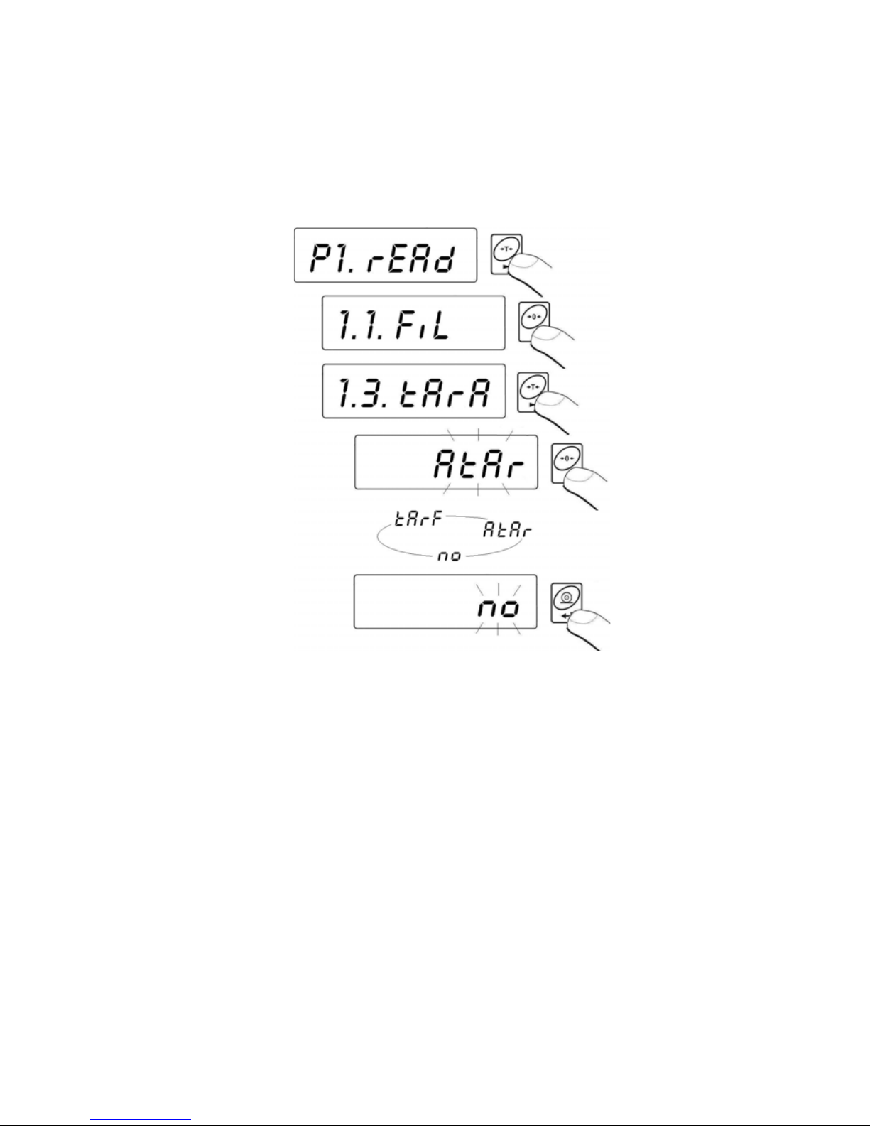
13.4. Tare function
This parameters enables users to configure a tare function.
Procedure:
x Enter the submenu <P1.rEAd> and then:
tArA AtAr
-
automatic tare function on and is stored in balance
memory after unplugging it from mains (Description
of function operating point 16.6 automatic tare)
tArA
no
-
automatic tare function off (user can turn on
operating of automatic tare F6 AtAr – till unplugging
the balance from mains)
tArA tArF
-
tare memory function – stores last value of tare in
balance memory. It is automatically displayed after
starting the balance. Value of tare is displayed with
minus sign, and there is Net symbol indicated on the
display. (user can turn on operating of automatic tare
F6 AtAr – till unplugging the balance from mains)
Return to weighing:
See - 11.2.2.
- 24 -
Page 25

14. RS 232 PARAMETERS
External devices connected to RS 232C have to be supplied from the
same mains and common electric shock protection. It prevents from
appearing a potential difference between zero leads of the two devices.
This notice does not apply to the devices that do not use zero leads.
Transmission parameters:
x Baud rate - 2400 – 38400 bit / s
x Data bits - 7,8
x Stop bits - 1,2
x Parity control - no, even, odd
There are four ways of sending data via RS232 interface:
xManually – after pressing
,
xAutomatically – after stabilizing the indication over -LO- threshold
xContinuously – after it is activated in parameter or by a command
sent via RS232
xOn external request - see - „List of scale - computer commands”.
The indication can be sent as:
xstable – the indication is sent after the scale stabilizes.
xany – the indication is sent immediately after pressing the
key,
this state is assign with <?> in the printout.
14.1. Printout type
This parameter is to select the type of printout.
Procedure:
x Enter the submenu <P2.Prnt> and then:
- 25 -
Page 26
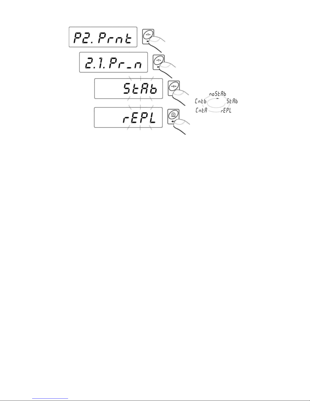
Pr_n noStAb
- immediate printout
(not accessible in verified scales)
Pr_n StAb
- sending stable results
Pr_n rEPL
- automatic operation
Pr_n CntA
- continuous transmission in basic unit
Pr_n Cntb
- continuous transmission in present unit
Return to weighing:
see 11.2.2.
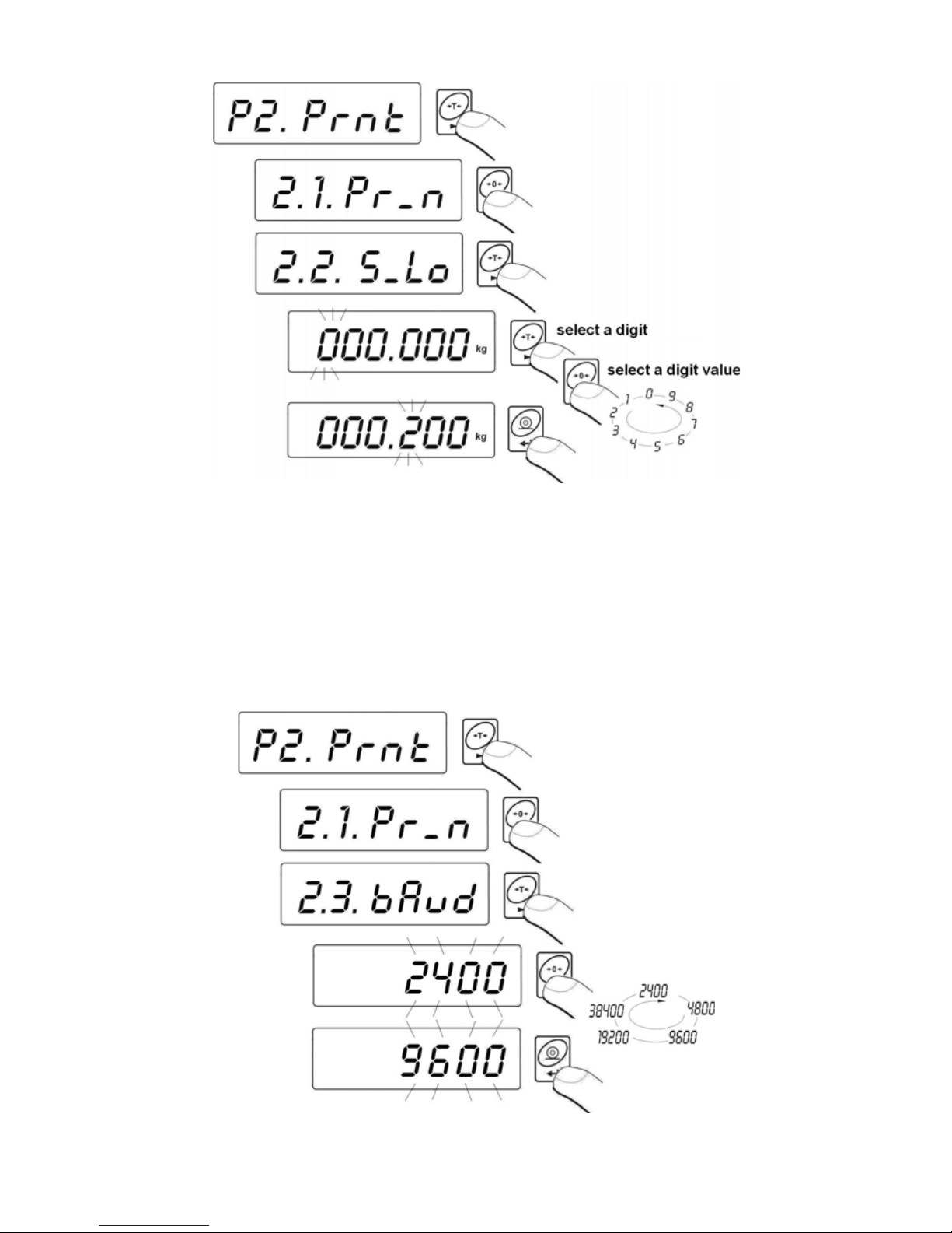
14.2. Minimal mass threshold
This function is necessary while working with automatic tare
or automatic operation or weighing animals.
Automatic tarring will not be applied until the indication (gross)
is lower than the value inscribed in S_Lo parameter.
In automatic operation measurements (net) are sent via RS232
when the indication is equal or greater than the value inscribed
in S_Lo parameter.
Weighings animals is performer when the indication is equal
or greater than the value inscribed in S_Lo parameter.
Procedure:
x Enter the submenu <P2.Prnt> and then:
- 26 -
Page 27
Return to weighing:
see 11.2.2.
14.3. Baud rate
Procedure:
x Enter the submenu <P2.Prnt> and then:
- 27 -
Page 28
Return to weighing:
see 11.2.2.
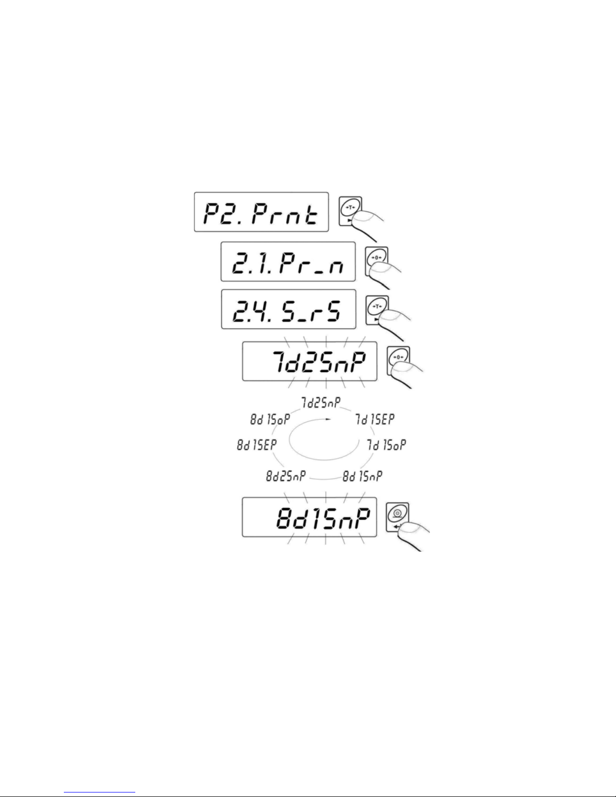
14.4. Serial transmission parameters
Procedure:
x Enter the submenu <P2.Prnt> and then:
7d2SnP - 7 data bits; 2 stop bits, no parity control
7d1SEP - 7 data bits; 1 stop bit, EVEN parity control
7d1SoP - 7 data bits; 1 stop bit, ODD parity control
8d1SnP - 8 data bits; 1 stop bit, no parity control
8d2SnP - 8 data bits; 2 stop bits, no parity control
8d1SEP - 8 data bits; 1 stop bit, EVEN parity control
8d1SoP - 8 data bits; 1 stop bit, ODD parity control
Return to weighing:
See 11.2.2.
- 28 -
Page 29
15. OTHER PARAMETERS
The user can set parameters which influence the scale operation.
They are gathered in the submenu <P5.othr> e.g. backlight and beep
signal. Enter this submenu <P5.othr> according to chapter 11.2.
15.1. Backlight function
Program recognises the way the scale is supplied (mains, battery)
and automatically selects the way of operating on the backlight:
bl – for mains,
blbt – for batteries or rechargeable battery pack.
15.1.1. Backlight for supplying from mains
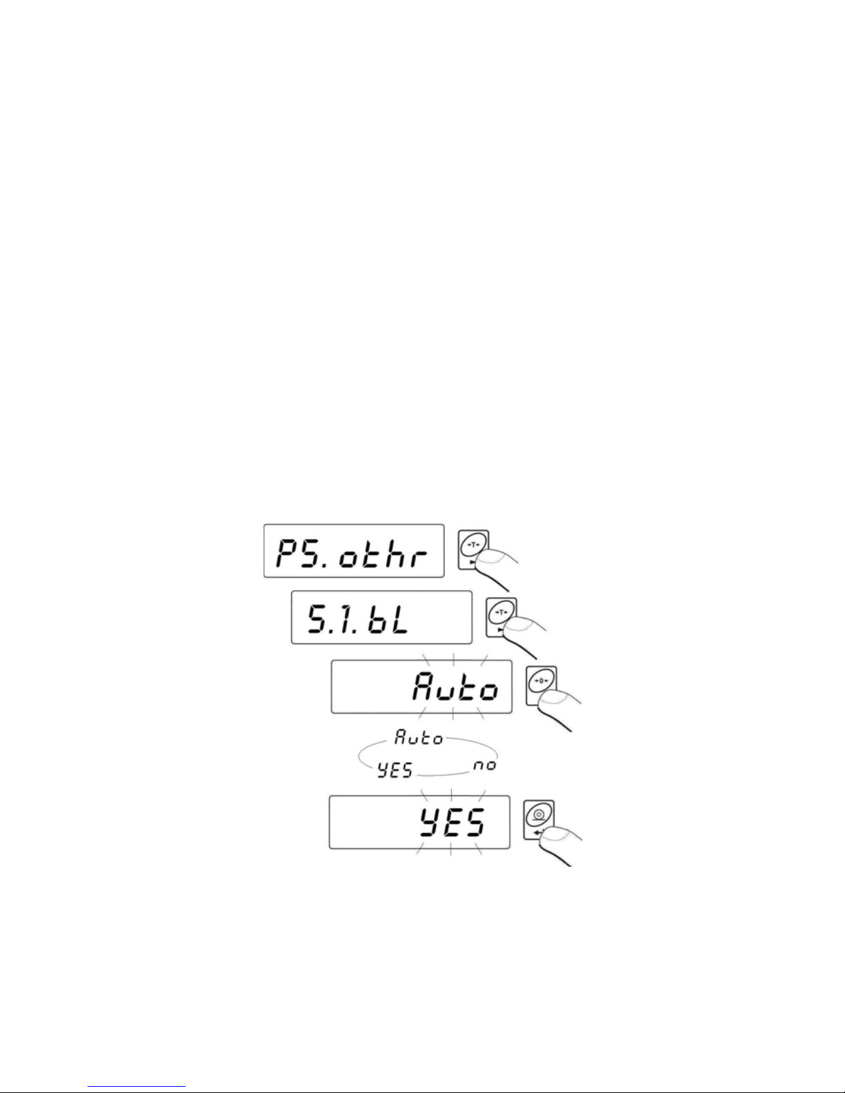
Procedure:
x Enter the submenu <P5.othr> and then:
bL no
- backlight switched off
bL YES
- backlight switched on
bL Auto
- backlight switched off automatically if indication
becomes stable for about 10s
- 29 -
Page 30
Return to weighing:
See 11.2.2.
Notice:
When bl=Auto, and the indication has not changed for 10s,
the backlight is automatically switched off. The backlight is
switched on again automatically after the result changes.
15.1.2. Backlight for supplying from batteries
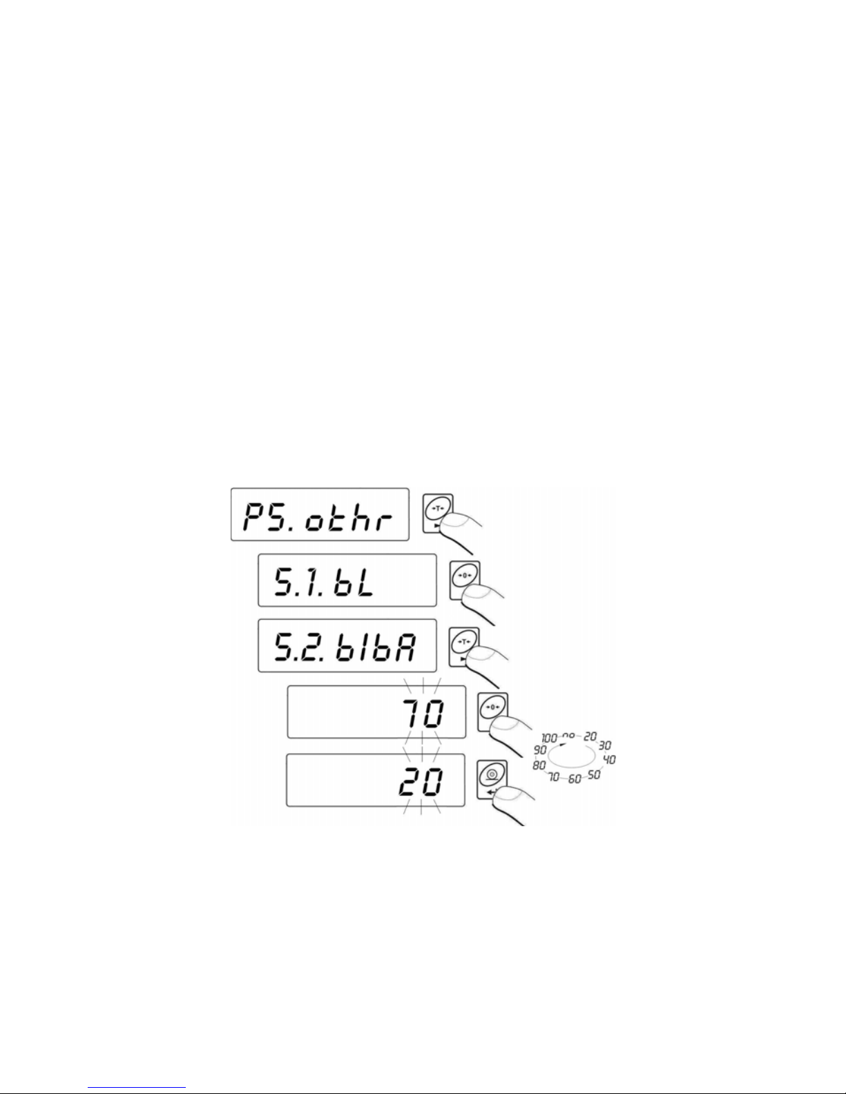
The user can change the intensity of backlight from 0% to 100%.
The lower the intensity is the longer the scale operates without
recharging or exchanging batteries. When the intensity is set
this function works as AUTO (described above).
Procedure:
x Enter the submenu <P5.othr> and then:
Return to weighing:
See 11.2.2.
Notice:
The more intense the backlight is the shorter the scale operates
on batteries.
- 30 -
Page 31
15.2. “Beep” signal – after pressing a key
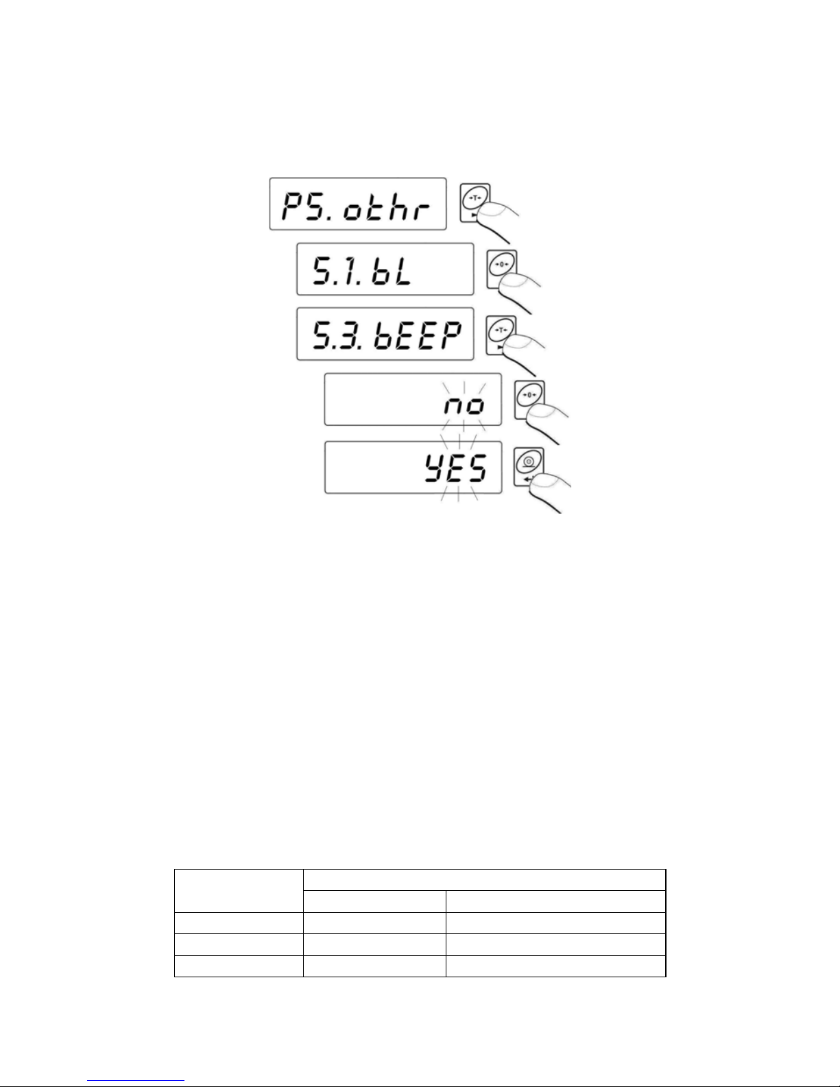
Procedure:
x Enter the submenu <P5.othr> and then:
bEEP no - switched off
bEEP YES - switched on
Return to weighing:
See 11.2.2.
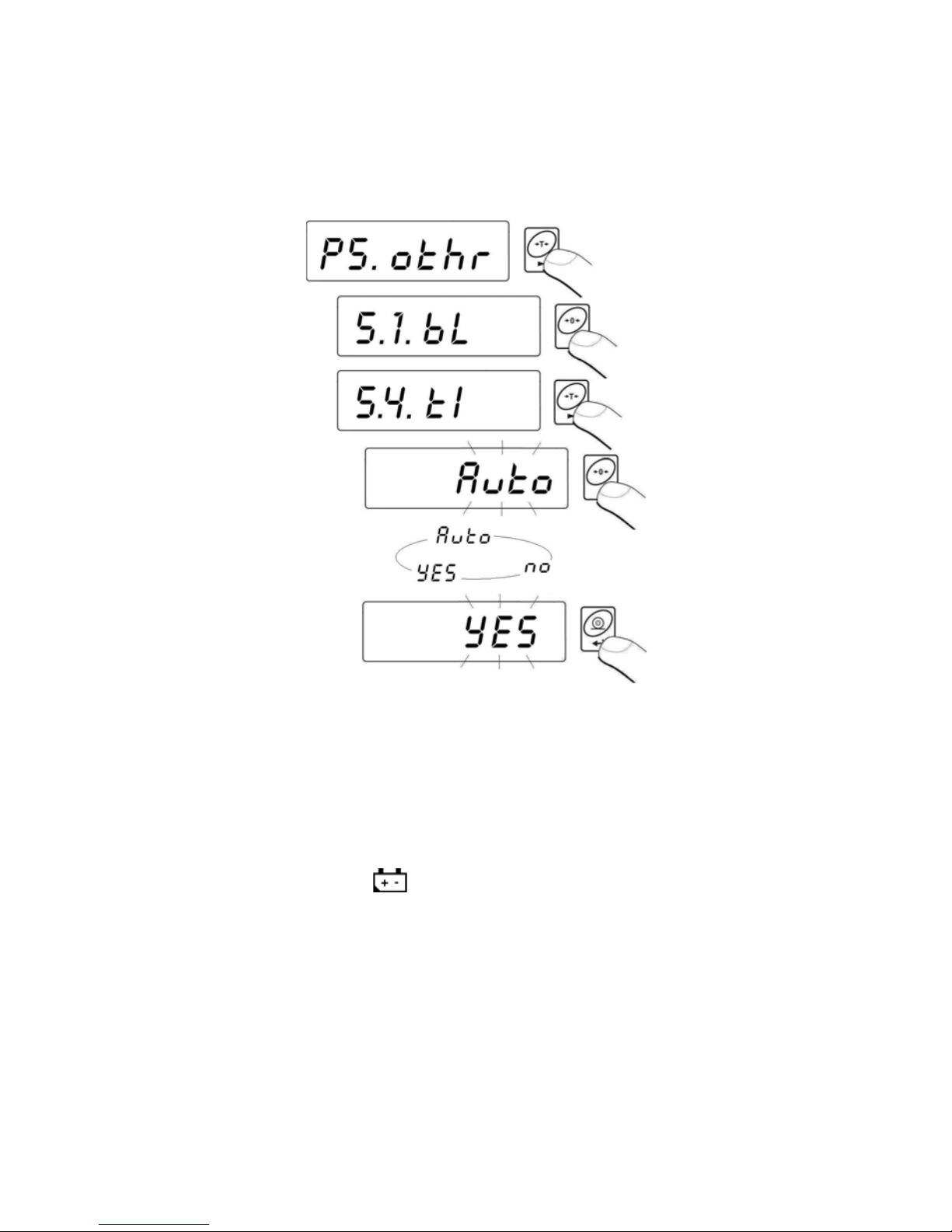
15.3. Automatic switch-off
This function is essential to save the battery power. The scale is switched
off automatically when (function t1 = YES) no weighing appears in 5
minutes. (no changes on the display). In case when this function disrupts
the operation (e.g. long time weighing procedures) or while working with
connection to mains, switch off this function.
Operation according to the power supply:
Operation
Setting
Mains Batteries / accumulator
t1 = 0 disabled disabled
t1 = YES enabled enabled
t1 = Auto * disabled enabled
- 31 -
Page 32
* automatic enabling/disabling according to the source of power.
Procedure:
x Enter the submenu <P5.othr> and then:
Returnto weighing:
See 11.2.2.
15.4. Battery voltage level check
While supplying from batteries too low level of voltage is measured
by software the pictogram
is displayed. It means that charging
or exchanging batteries is required.
15.4.1. Checking the batteries
This function is to check the level of battery supply. It works only if:
x Weighing mode is set,
x Battery supply is set in parameters.
- 32 -
Page 33
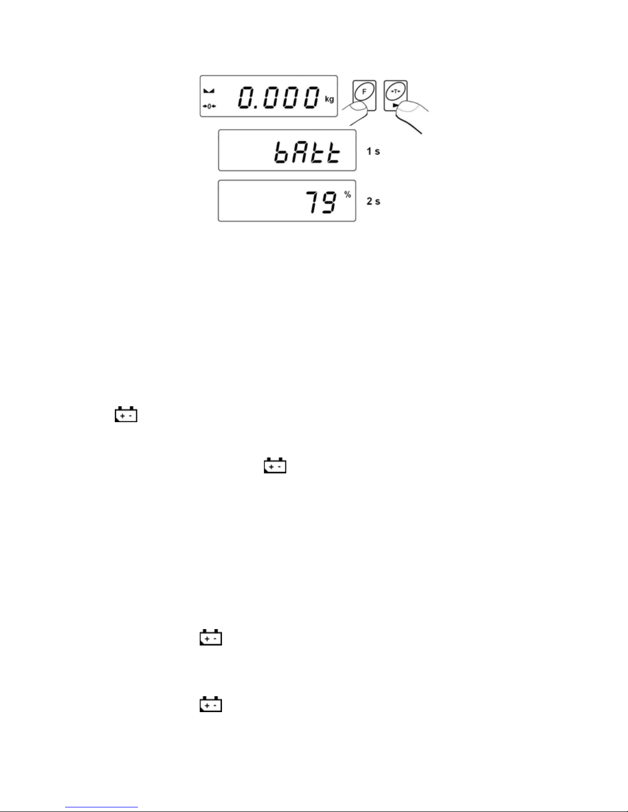
Procedure:
After displaying the level of batteries (in per cents) the program returns
to weighing.
15.4.2. Battery discharge pictogram
The symbol (bat low) switches on when the voltage level drops to 18%
of the accepted level of voltage. It means that charging or exchanging
batteries is required.
Low level of batteries:
x
pictogram on the display,
x After some time the device will automatically switch off
to protect the batteries from destructible discharging,
x Charging is signalled by
(blinking period about 2 seconds)
on the display.
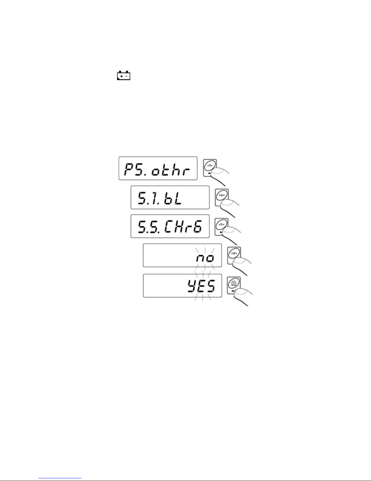
15.4.3. Accumulator charging option
This function allows to switch on charging algorithm for NiMH batteries
(for scales of WLC C1…C2, WLC/B1 series) or a gel cell SLA
accumulator (for scales of WLC/A2, WLC…/C/2 series):
a) Parameter <CHr6> set to <no>:
x Pictogram
does not appear, charging disabled,
x During software initializing, after turning on <bAtt>.
b) Parameter <CHr6> set to <YES>:
x Pictogram
blinks slowly (period about 2 seconds),
charging is enabled,
- 33 -
Page 34
x Message <nImh> appears on the display (for scales
of WLC C1…C2, WLC/B1 series) or <SLA> (for scales
of WLC/A2, WLC…/C/2 series),
x In case of damaging accumulators or lack of it the
pictogram
blinks quickly (period about 0.5 sec).
Notice:
WLC C1…C2 and WLC/B1 scales are equipped with NiMH batteries
packs, R6 (AA) size and Power adapters for supplying from mines.
Procedure:
x Enter the submenu <P5.othr> and then:
CHr6 YES - enabled
CHr6 no - disabled
Return to weighing:
See 11.2.2.
15.4.4. Formatting rechargeable battery packs
WLC C1…C2 and WLC/B1 scales are equipped with NiMH batteries
packs, R6 (AA) size and Power adapters for supplying from mines.
They need formatting after first powering up. It is crucial for batteries
lifetime to undertake this process. Formatting consist in charging and
total discharging (without meantime charging).
- 34 -
Page 35
Procedure:
1. Supply the indicator from mains,
2. Charge batteries for 12 hours (time of charging 2200mAh batteries),
3. After 12 hours unplug from mains,
4. Use the device up to the moment of self powering down,
5. Repeat the process of charging starting from point 1.
Notice:
They reach their optima capacity after three cycles of full charging
and discharging.
16. OPERATION MODES
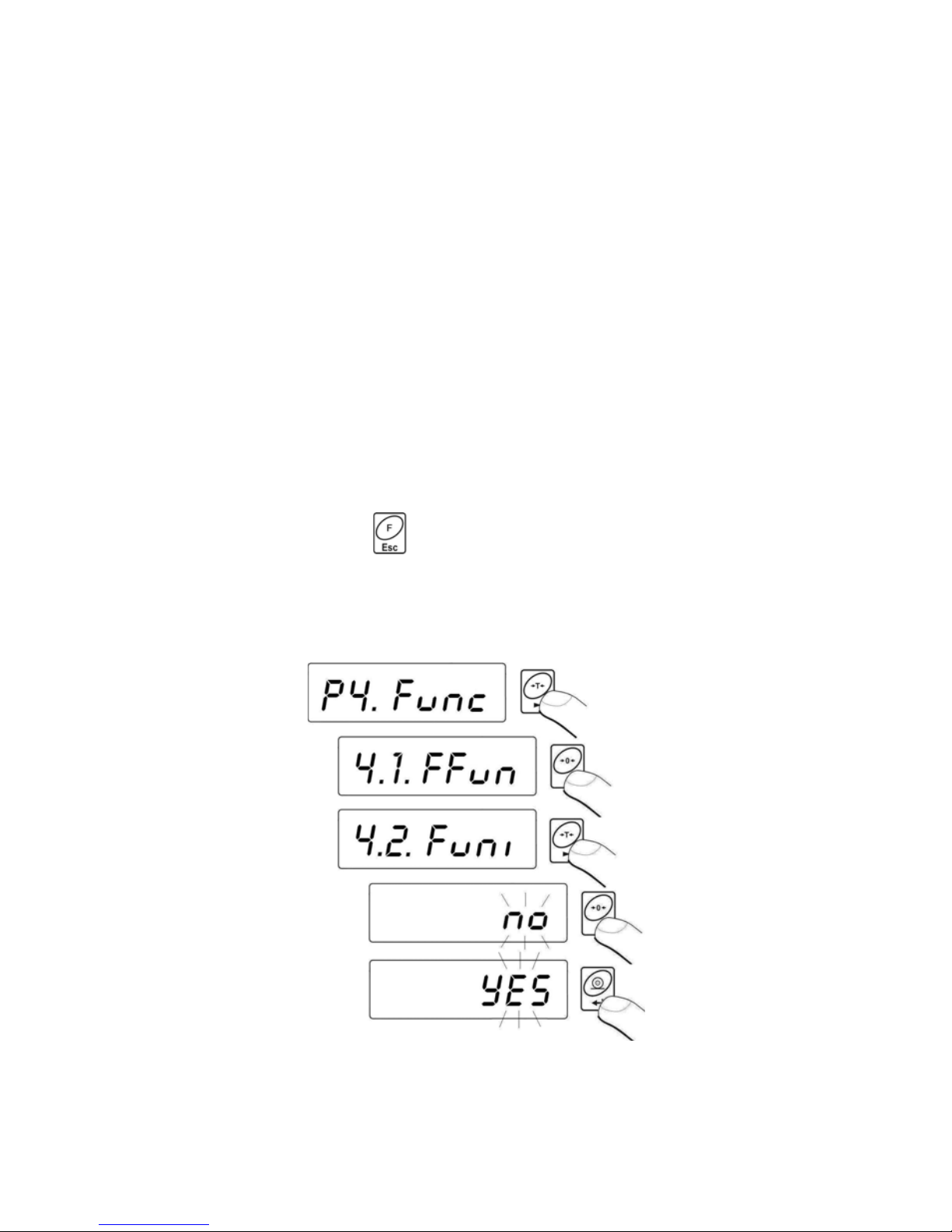
16.1. Setting accessibility of operation modes
In this parameter group users can disable/enable accessibility
of functions after pressing
key.
Procedure:
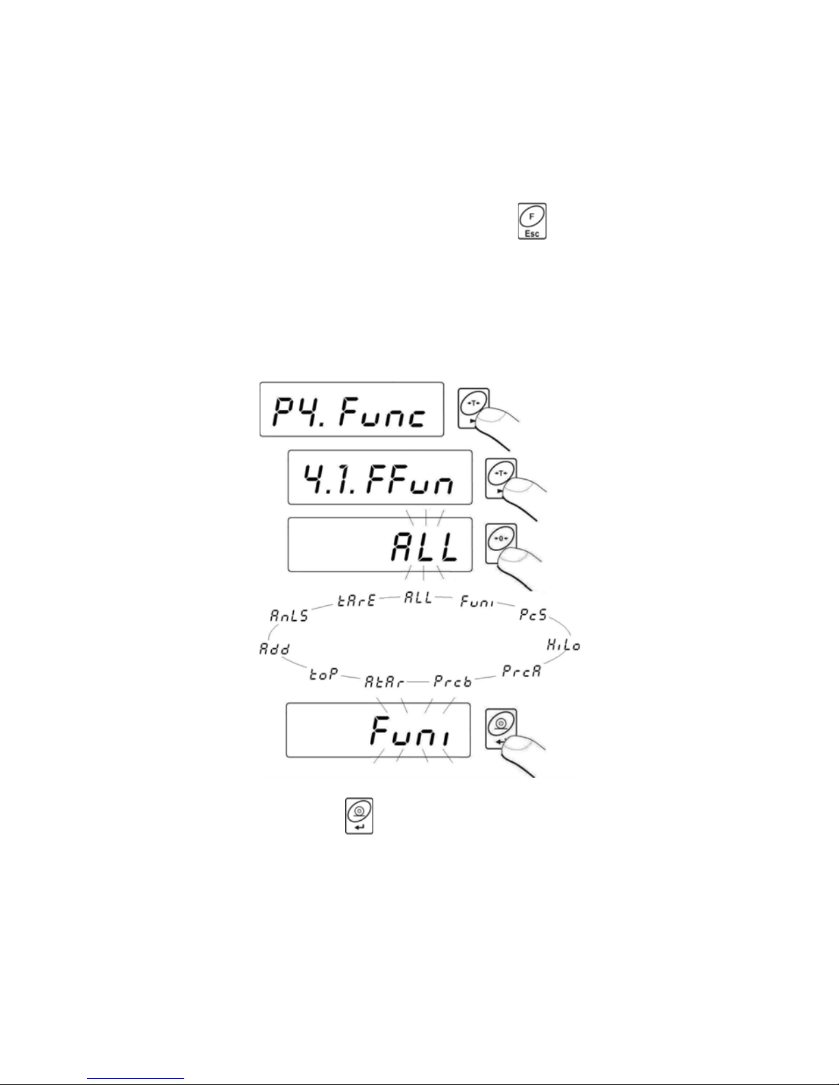
x Enter the submenu <P4.Func> and then:
no – mode is disabled
YES – mode is enabled
- 35 -
Page 36
Return to weighing:
See 11.2.2.
16.2. Selecting quantity of operation modes
This function enables user to set if ,after pressing
key, all operating
modes will be accessible (ALL) or only one from the list chosen and
used by operator.
Procedure:
x Enter the submenu <P4.Func> and then:
After choosing setting press
key. The program will return
to displaying name of submenu <P4.1.FFun>.
Return to weighing:
See 11.2.2.
- 36 -
Page 37
16.3. Counting pieces of the same mass
Standard solution is equipped with option of counting small pieces of the
same mass. Counting pieces does not operate with other scale functions.
It is possible to execute a tare function in this operating mode in order to
tare a container value.
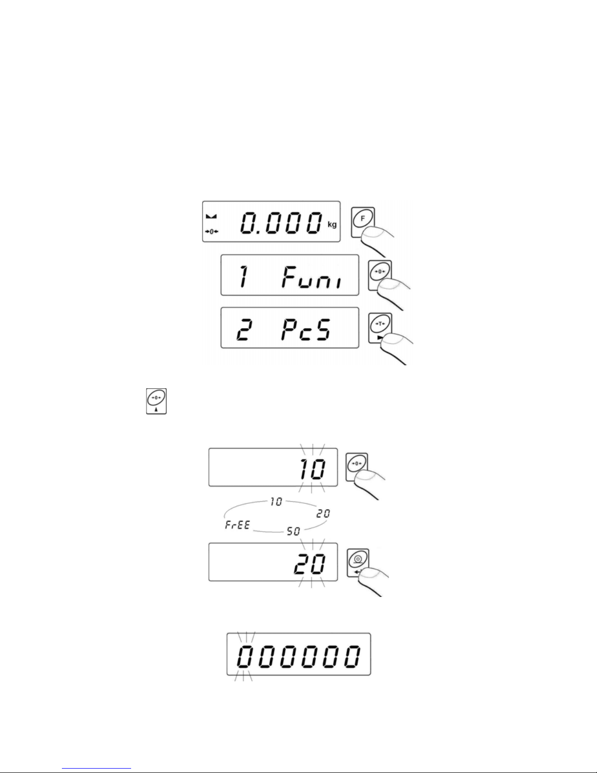
Procedure:
x Enter to <PcS> function:
x You will see a blinking value of sample quantity.
x Press
key to start setting quantity of sample, you have
a few options to chose from:
x If the <FrEE> option is selected you will see:
- 37 -
Page 38
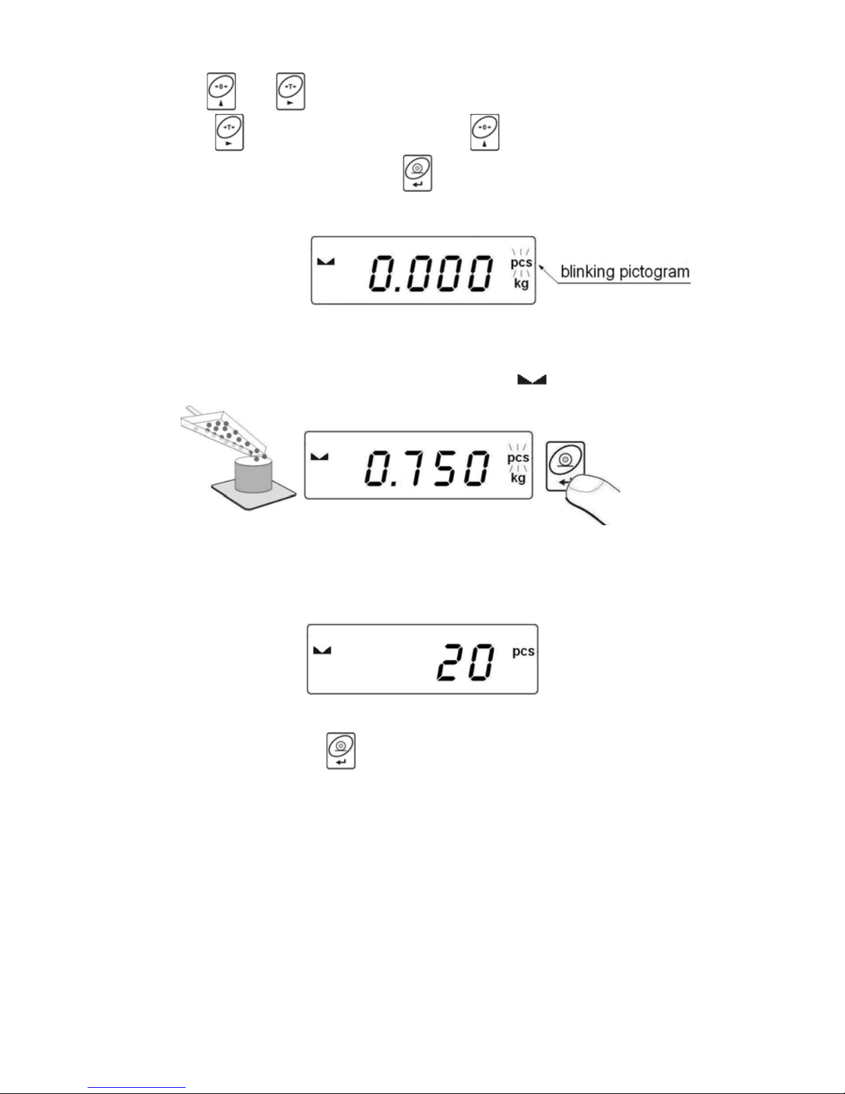
x Using
and enter the required sample quantity,
where:
- selection of digit position, - setting the digit,
x Confirm the value by pressing
,
x You will see <LoAd> on the display and then:
x If weighing is performed in a container put the container on the pan
first and then tare it. Then put the declared quantity of pieces on the
pan and confirm it when stable (signalled by
):
x The program will automatically calculate the mass of a single piece
and go on to the Piece Counting mode (pcs). You will see the
following display:
Notice:
1. If a user presses the
key when load is not present on the pan,
the message -Lo- will be indicated for a few seconds and the scale
will automatically return to weighing.
2. In order to comply with the rules of appropriate counting pieces put
as many pieces as possible during unit mass adjustment. Single
piece mass should not be less than 5 divisions.
3. If a single piece mass is lower than a reading interval d the display
will show the <Err5> message (see ch. 21. Error messages) and
short audible signal will be emitted than the scale returns to weighing.
- 38 -
Page 39
Return to weighing:
xPress the
key twice.
16.4. +/- control referring to the inscribed standard mass
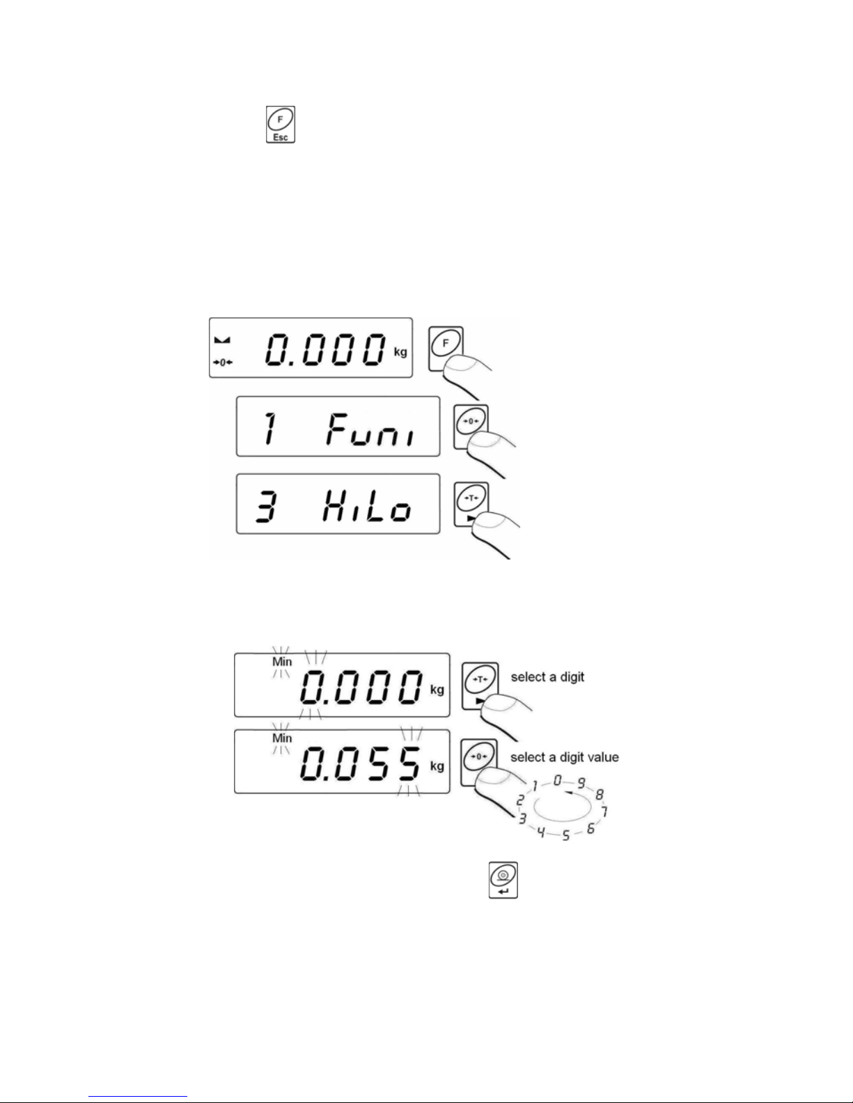
Procedure:
x Enter to <HiLo> function:
x The program enters the window of setting the lower threshold
of weighing (Min):
x The inscribed value confirm by pressing
, the program will
automatically go to the higher threshold of weighing (Max):
- 39 -
Page 40
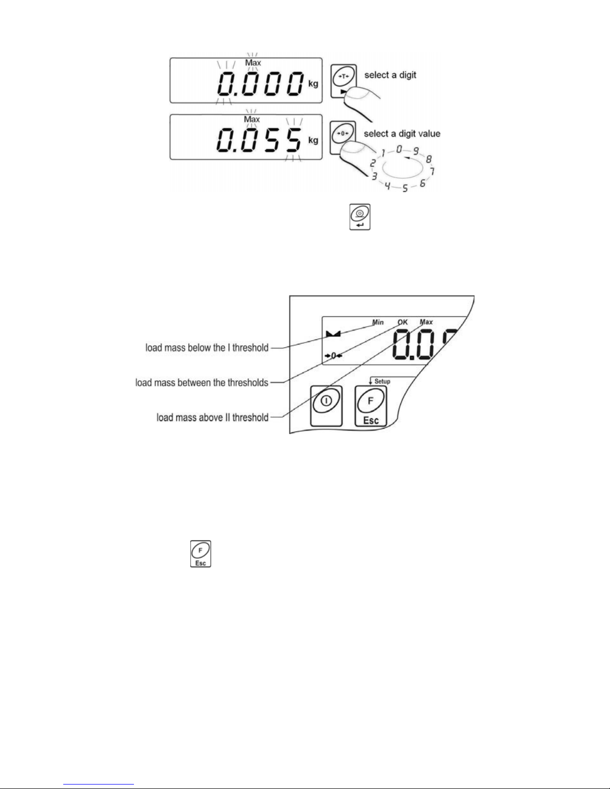
x The inscribed value confirm by pressing , the program will
automatically go to the main window,
x During setting threshold values following cases take place:
Notice:
If a user erroneously enters a value of the lower threshold higher than
the upper one, the scale will indicate an error message and will return
to weighing.
Return to weighing:
xPress the
key twice.
16.5. Control of % deviation referring to the inscribed standard mass
Scale software enables control of deviation (in %) of weighed loads
mass referring to the inscribed standard mass. Mass of standard can
be determined by its weighing (PrcA function) or entered to the scale
memory by an user (PrcB function).
- 40 -
Page 41
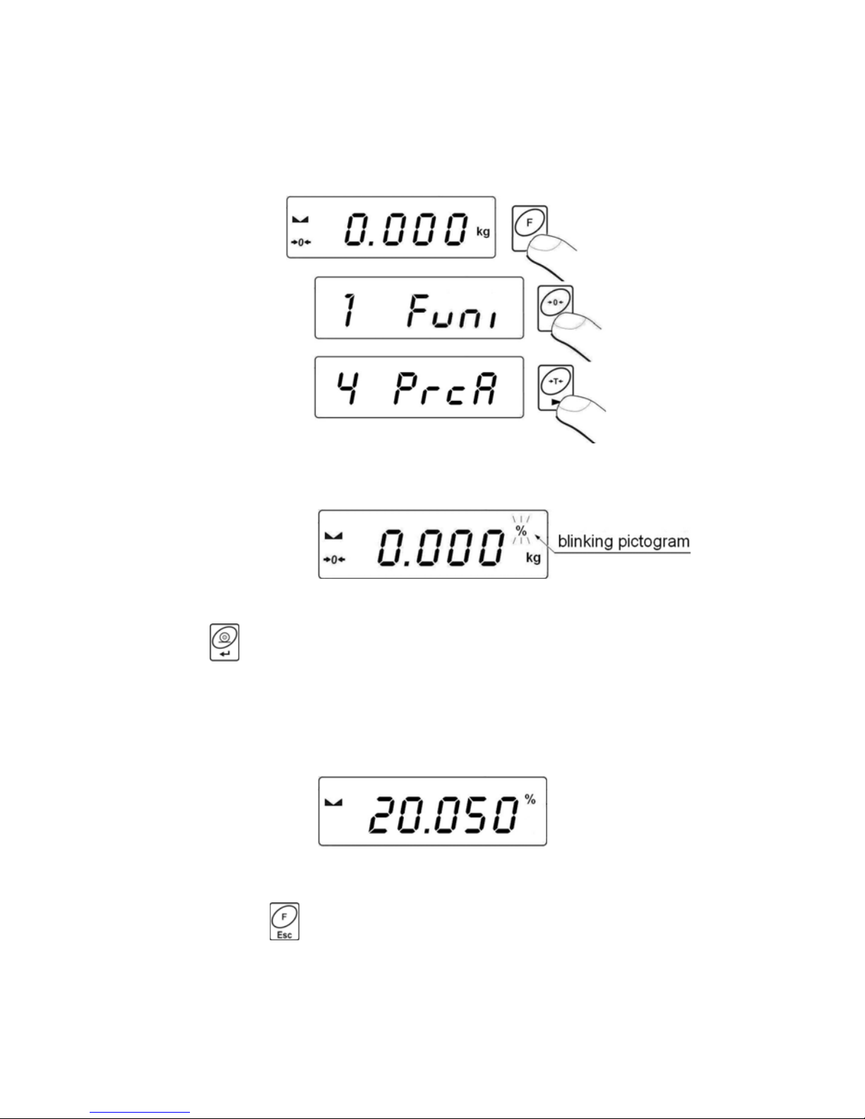
16.5.1. Standard mass determined by its weighing
Procedure:
x Enter to <PrcA> function:
x You will see <LoAd> on the display and then:
x place an load on the pan which mass will be accepted as standard,
x press
to confirm this operating mode,
x after few seconds the indication 100,00% will be displayed,
x From this moment display will not indicate mass of weighed load
but deviation of load mass placed on the pan referring to the mass
of standard (in %).
Return to weighing:
xPress the
key twice.
- 41 -
Page 42
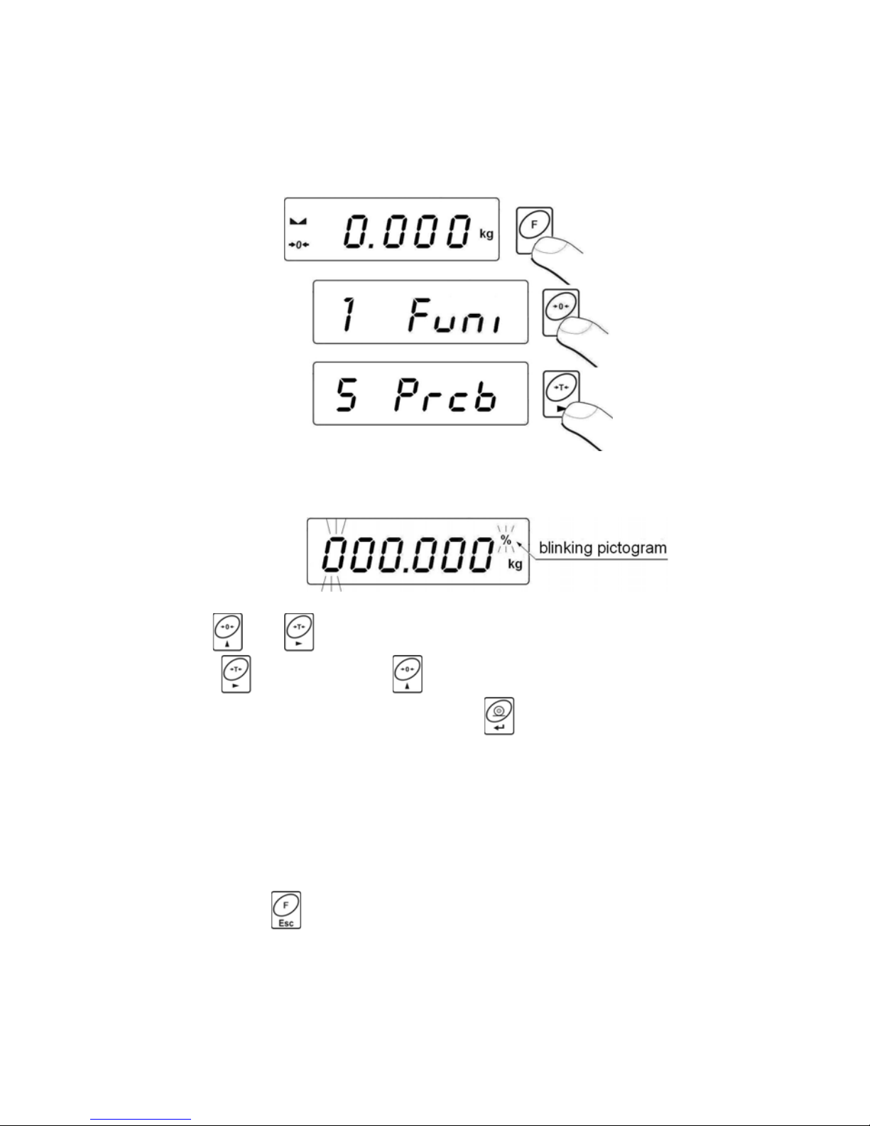
16.5.2. Mass of standard inscribed to scale memory
Procedure:
x Enter to <PrcB> function:
x Program wagowy przejdzie do wy!wietlania okna:
x Using
and set standard mass,
where:
- digit selection, - digit setting,
x Confirm the entered value by pressing
,
x You will see the indication equal to 0,000%,
x From this moment display will not indicate the mass of weighed
load but deviation of the load mass placed on the pan referring
mass of standard (in %).
Return to weighing:
xPress the
key twice.
- 42 -
Page 43
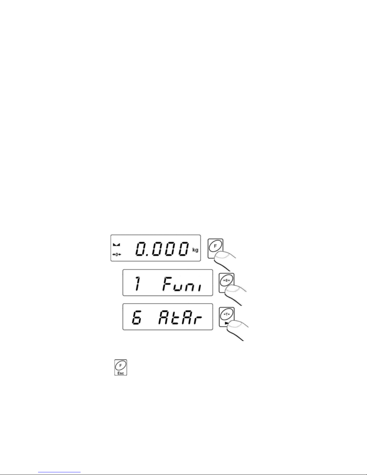
16.6. Automatic tare
This function is useful for fast net mass determination of weighed load
in case when tare value of is different for each load. In case when the
function is active the cycle of scales operating looks as follows:
x press zeroing key when the pan is empty,
x place the container for pieces,
x when indication is stable automatic tarring of the container mass will
be performed (Net marker will appear in the upper part of the display),
x place a sample into the package,
x display will indicate net mass of sample,
x remove the sample together with the container,
x display will indicate tare mass with minus sign,
x place a container for the next sample. When indication is stable
automatic tarring will take place (Net marker will appear in the
upper part of the display),
x place next sample into the package.
Procedure:
Return to weighing:
xPress the
key twice.
- 43 -
Page 44
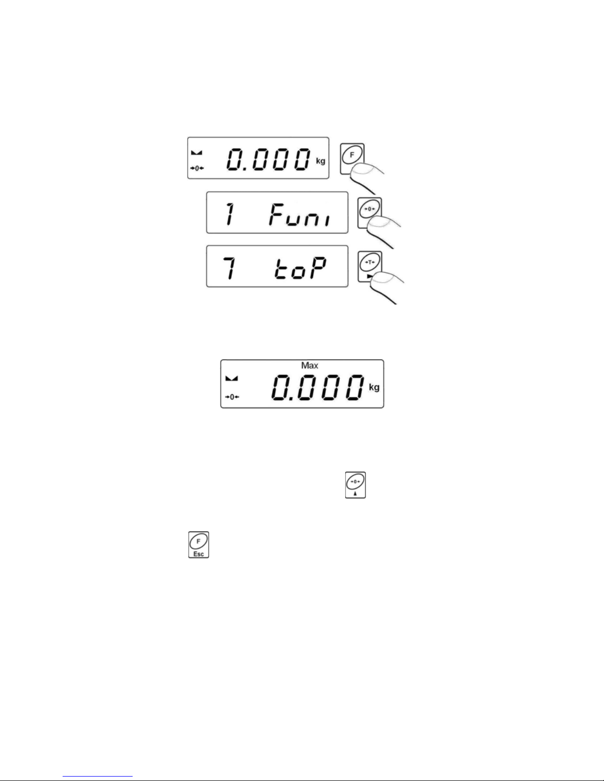
16.7. Measurement of maximal force on the pan – latch
Procedure:
x Enter to <toP> function:
x Confirmation of choice of <toP> function is indication of the Max
pictogram:
x Apply a force to the weighing pan,
x The display of scale will latch the maximum value of the force,
x Remove loads from the pan,
x Before the next measurement press the
key.
Return to weighing:
xPress the
key twice.
16.8. Totalizing
Scale software is equipped in a totalizing function of single weighings.
The totalizing procedure can be documented on the printer connected
to the indicator.
- 44 -
Page 45
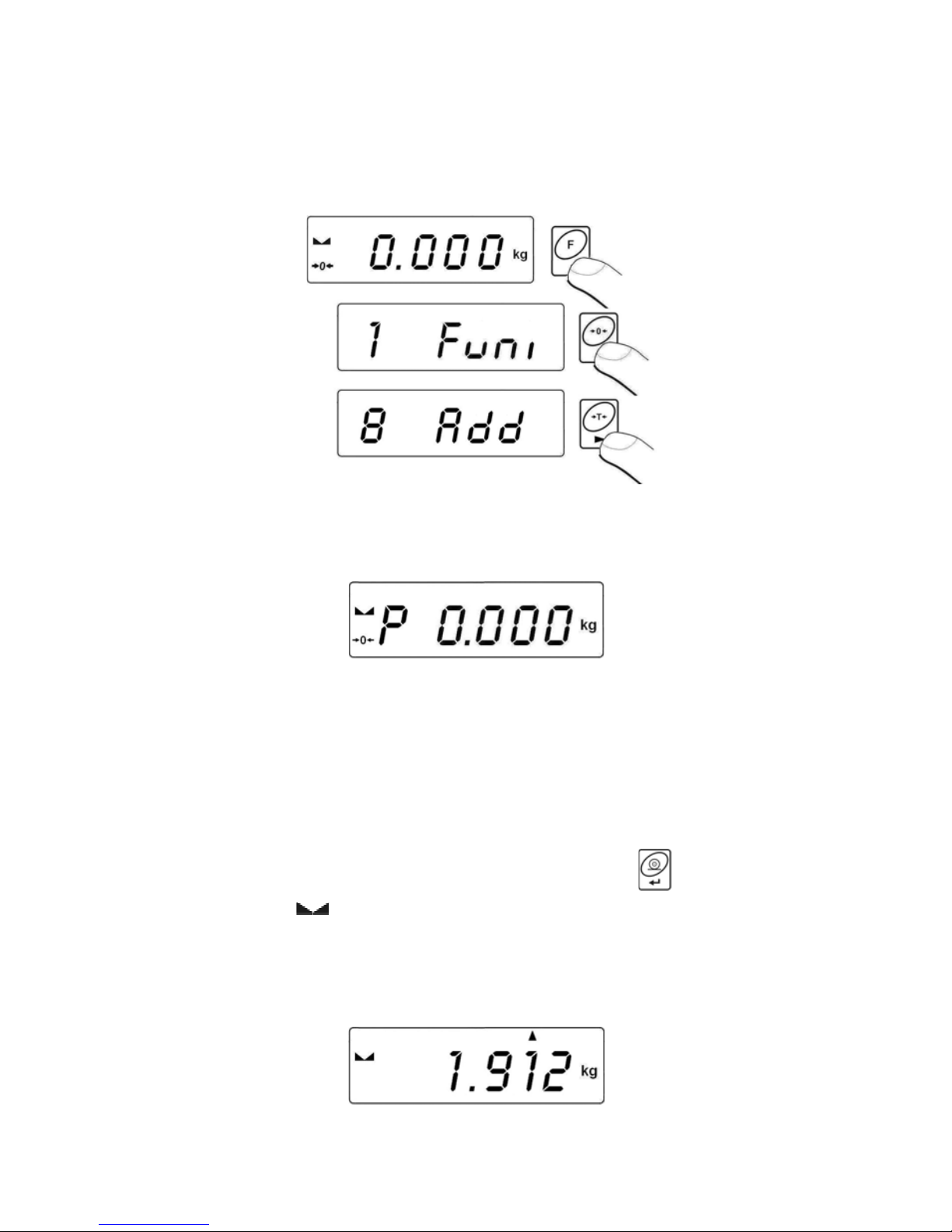
16.8.1. Enabling the work mode
Procedure:
x Enter to <Add> function:
x A letter „P” in the left side of the display is a confirmation that
<Add> function have been selected:
16.8.2. Totalizing procedure
x Enter <Add> function according to ch. 16.8.1,
x Put the first load on the pan. If the weighing procedure is performed
in a container put the container on the pan first and tare it. Then put
the first load on the pan and confirm it by pressing
when stable
(signalled by
),
x You will see a sum of weighings on the display, the „"” pictogram
in the upper right corner will be displayed and the weighing result
will be printed on the printer connected to the indicator.
- 45 -
Page 46
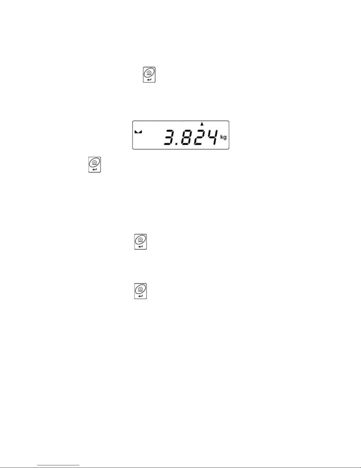
x Take off the load from the pan, indication returns to ZERO
and the letter „P” in the left part of the display appears,
x Put the next load on the pan,
x After stabilizing press
, the sum of first and second weighing will
appear on the display, the „"” pictogram in the upper right corner
will be displayed and the second weighing result will be printed
on the printer connected to the indicator:
x Press to complete the procedure (with the loaded or unloaded
pan), a sum of all weighings will be printed:
(1) 1.912 kg
(2) 1.912 kg
----------------------- TOTAL: 3.824 kg
x In case of pressing
one more time with loaded pan, you will see
the <unLoAd> message. Unload the pan, the scale will return to
ZERO and the letter „P” in the left part of the display will appear.
The scale is ready for the next procedure.
x In case of pressing
one more time with loaded pan, you will see
the letter „P” in the left part of the display will appear. The scale is
ready for the next procedure.
16.8.3. Memory of the last value of sum of weighed goods
After interrupting (e.g. switching off) the totalizing procedure, it is possible
to restart the procedure without loosing data. In order to do it just enter
the totalizing procedure:
x Enter <Add> function again according to the ch.16.8.1 of the manual,
x You will see the last memorized sum of weighings on the display
- 46 -
Page 47
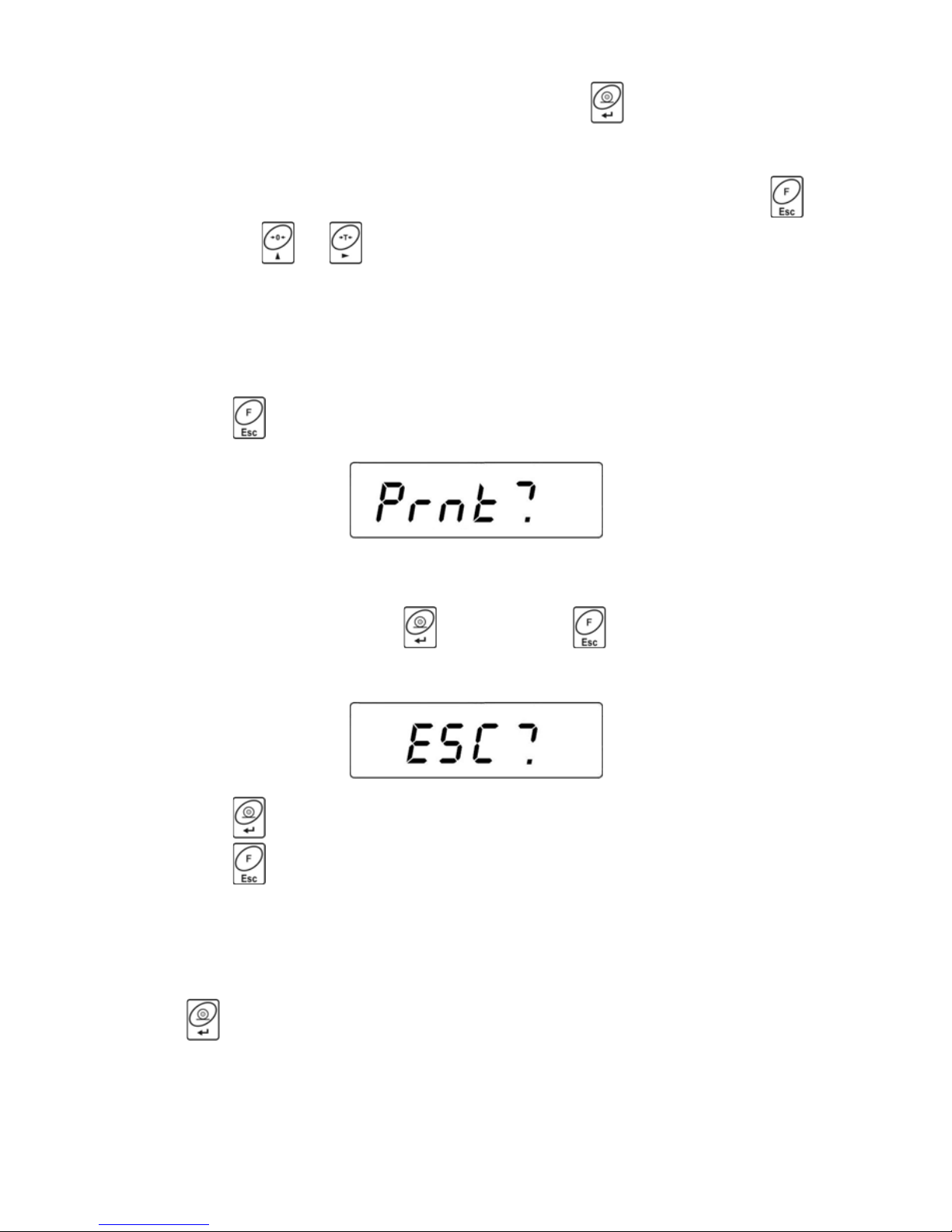
- In order to continue the procedure press
, the indication
returns to ZERO and the letter „P” appears in the left part of the
display. The scale is ready for weighing,
- In order to terminate the previous totalizing procedure press
key,
, or . You will see the letter „P” in the left part of the
display. The scale is ready for weighing.
16.8.4. Return to weighing
x Press
key, you will see:
x Before leaving the <Add> function it is possible to print out
subsequent weighings and the sum of weighings on the
connected printer (press
to print, press to cancel).
x The following message will appear on the display:
x Press key to return to weighing,
x Press
to return to totalizing.
Notice:
In case of overflow of the range of the display in totalizing you will see
<5-FULL> message in the display. In that case unload the pan and
press
to complete the procedure with a printout of sum of all
weighings or put a lower mass on the pan which does not cause
the overflow error.
- 47 -
Page 48
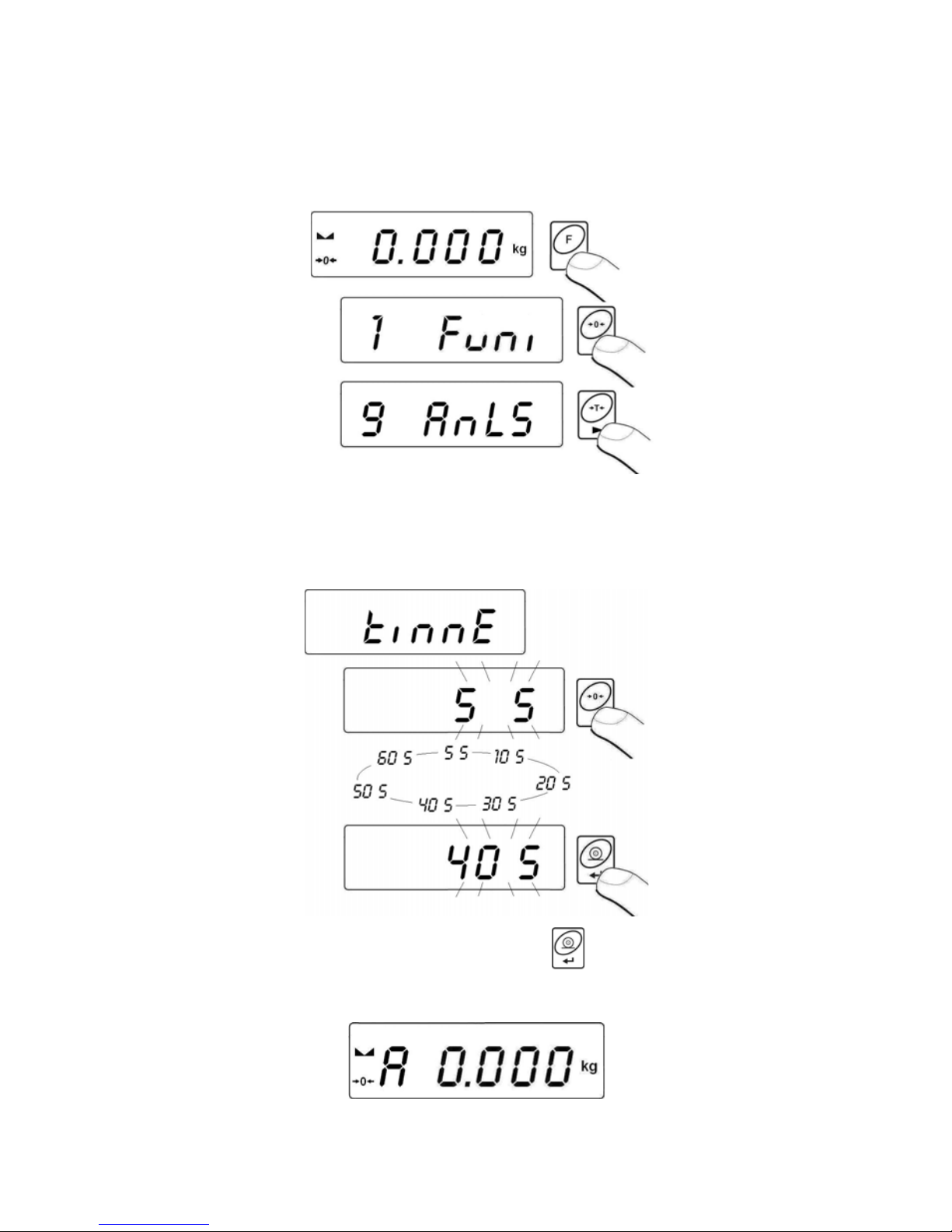
16.9. Weighing animals
Procedure:
x Enter to <AnLS> function:
x The <tinnE> message appears on the display for 1s, and then the
program goes to the window of setting the duration time (in seconds)
of the animal weighing process:
x Confirm the selected value by pressing ,
x You will see the following window:
- 48 -
Page 49
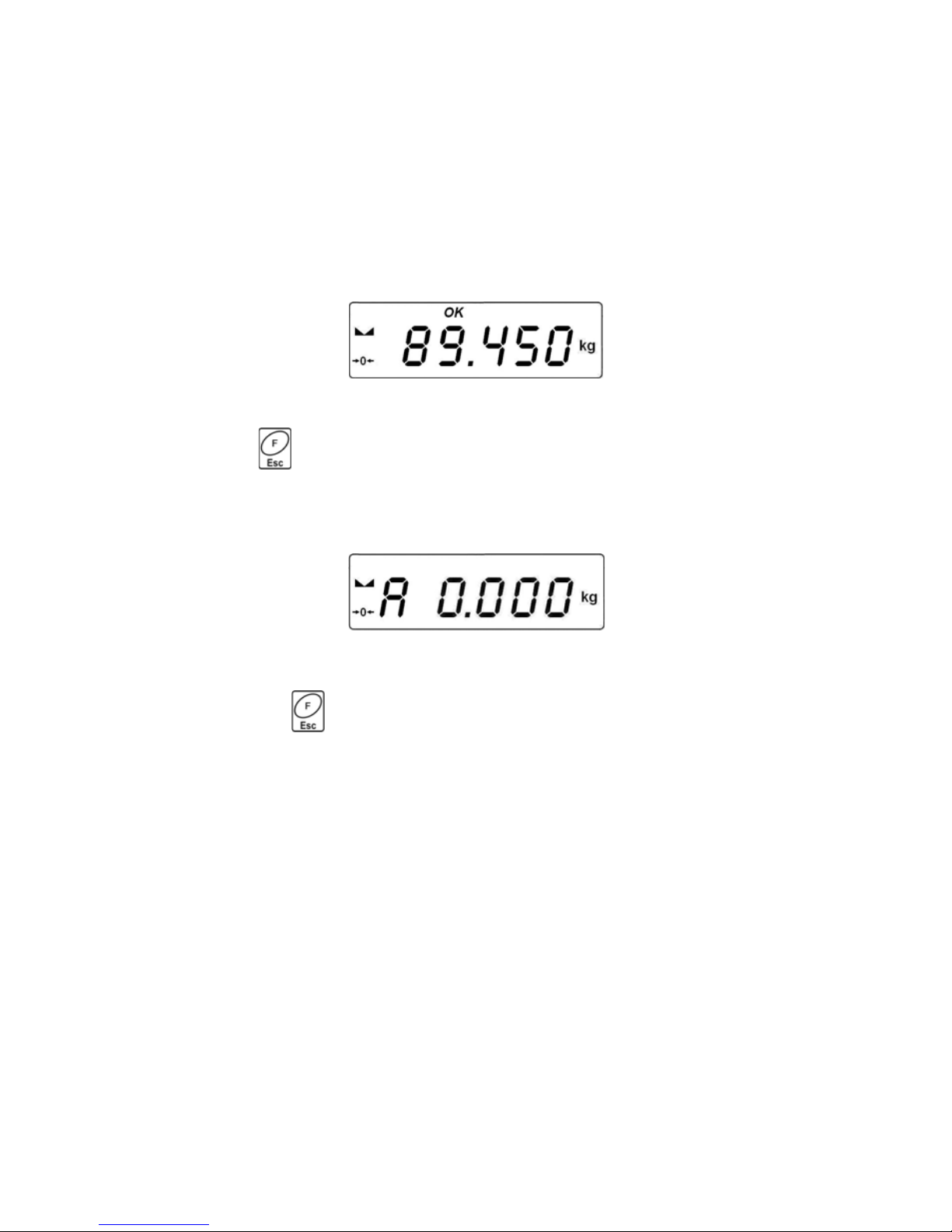
x Load an animal to the platform,
x After exceeding the -LO- value (see 14.2), program starts the
weighings process. The appearance of subsequent hyphens
< - - - - - - - > showing the progress,
x After completing the process of weighings the result is latched
on the display and additionally the OK pictogram is shown in
the upper part of the display:
x You can start the procedure of weighing animals again by
pressing
,
x After removing the animal from the platform program returns
to the window:
Return to weighing:
xPress
.
16.10. Tare memory
Users are allowed to Enter Up to 9 tare values to the memory.
16.10.1. Entering the tare value to the scale memory
Procedure:
x Enter to <tArE> function:
- 49 -
Page 50
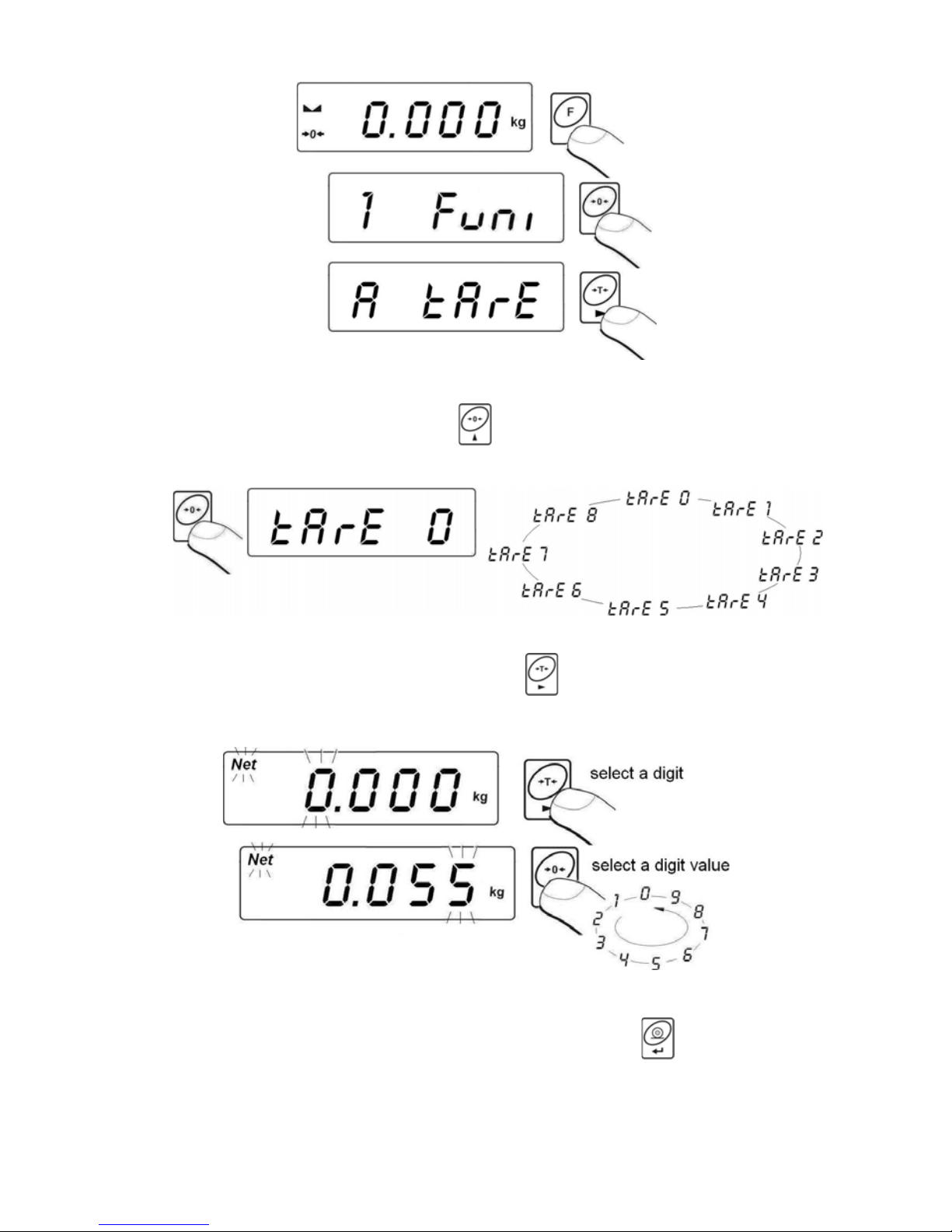
x The program goes to displaying the first value from the selection
of tare values <tArE 0> (press
to chose different values):
x After selecting the right position press and you will see
an editing field:
x Enter the selected tare value to the scale memory
,
- 50 -
Page 51
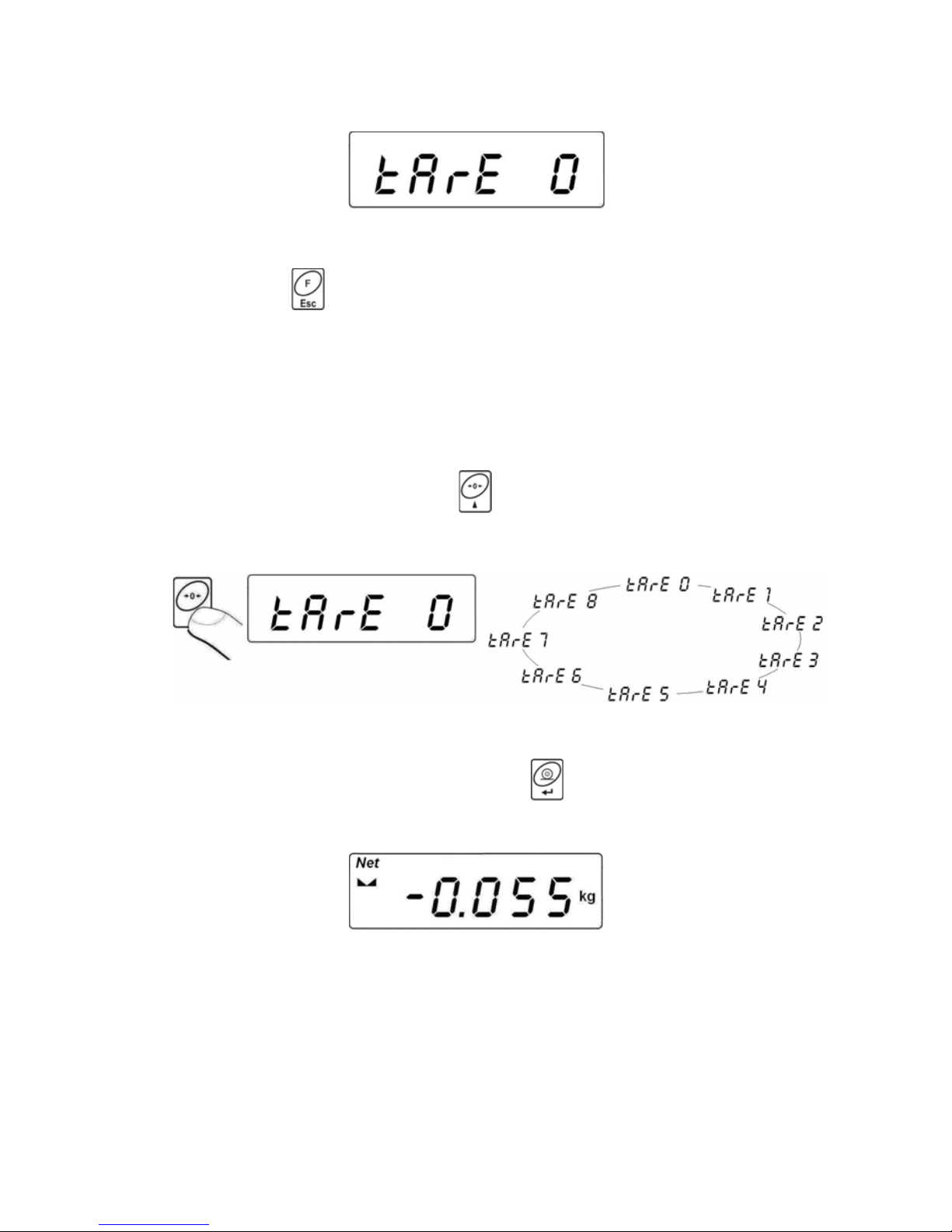
x The program returns to the following window:
Return to weighing:
xPress
.
16.10.2. Selecting a tare value from the memory
x Enter <tArE> function according to the ch. 16.10.1 of the manual,
x The program goes to displaying the first value from the selection
of tare values <tArE 0> (press
to chose different values):
x
To use an entered tare value press
, you will see the tare value
on the display preceded by the „-„ sign and the Net pictogram:
Caution:
A tare value from the memory is not remembered after powering off
and on the scale.
- 51 -
Page 52

- 52 -
17. SCALE CALIBRATION
In precise scales changes of gravitational acceleration have noticeable
influence. The gravitational acceleration changes with altitude and
latitude. Every scale has to be adjusted to the place of use especially
when the place changes. Frequent calibration also prevents weighing
process from the influence of humidity and temperature.
For assuring the maximal accuracy of weighing a periodical user
calibration is required.
Calibration should be performed:
x Before weighing process,
x After a long break between series of measurements,
x After the ambient temperature change.
Conditions of trigerring off calibration:
x Automatic internal calibration:
Started by adequate temperature change,
Started after adjusted time period,
Started after powering up the device,
x Manual internal calibration started from the keyboard,
x Calibration with an external weight.
Caution:
Internal calibration is accessible only in WLC…/C/2 scales of WLC series.
In WLC…/C/2 scales calibration with an external weight is not accessible.
It should be remembered that the calibration process should be performed
with the empty pan! The calibration process can be terminated by
pressing Esc when necessary.
17.1. Internal calibration
An option for WLC…/C/2 scales of WLC series only
The internal calibration process can be initiated manually or automatically.
Press Cal to initiate it manually. Automatic calibration system performs
internal calibration and informs a user on the display about the course
of the process.
Page 53
17.1.1. Manual internal calibration
Procedure:
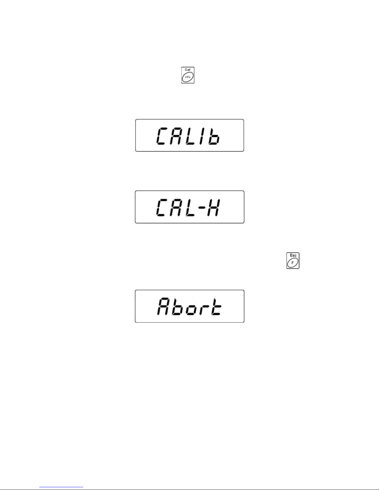
x While in weighing mode press
,
x The scale program starts to check stability conditions for the
calibration process and displays the following message:
x Then the program automatically goes to the internal calibration
procedure which is signalled by the following message:
x After completion of the calibration process program returns
to the weighing mode,
x Calibration process can be terminated anytime by pressing
which is signalled by the following message on the display:
Notice:
1. It should be remembered that internal calibration should
be performed with unloaded pan with keeping possibly
constant ambient conditions.
2. If the calibration process lasts longer than 15 seconds scale
software will react with <Err8> displayed and a short sound
and then the calibration procedure will start again.
- 53 -
Page 54
17.1.2. Automatic internal calibration
The automatic calibration process can be triggered off by 3 different
factors:
xCalibration after powering up
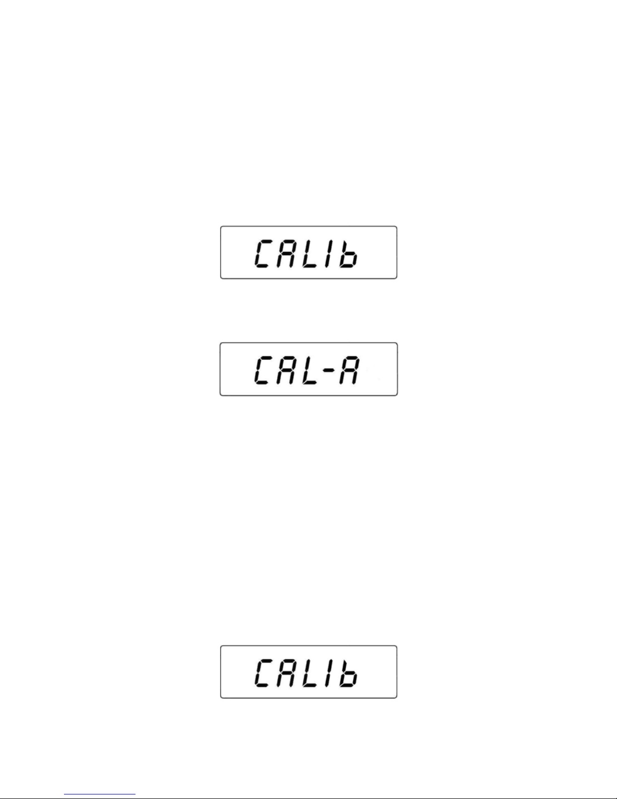
After performing the start procedure the scale program starts
to check stability conditions for the calibration process and
displays the following message:
Then the program automatically goes to the internal calibration
procedure which is signalled by the following message:
After completion of the calibration process program returns
to weighing mode.
xCalibration triggered off by temperature changes
The scale has been equipped in the temperature monitoring
system;
Temperature triggers off calibration every time when the internal
system measures the temperature change greater than 3°C;
The calibration procedure triggered off by the temperature
change starts with checking which is signalled by the
following message:
- 54 -
Page 55
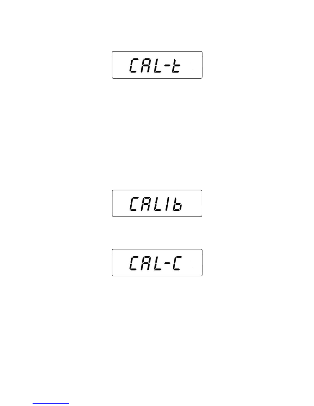
Then the program automatically goes to the internal calibration
procedure which is signalled by the following message:
After completion of the calibration process program returns
to the weighing mode.
xCalibration triggered off by timer
The time condition for subsequent automatic calibration is 3
hours. It means that, when no other triggering factor appear,
the calibration will appear every 3 hours;
The calibration procedure triggered off by the time change starts
with checking which is signalled by the following message:
Then the program automatically goes to the internal calibration
procedure which is signalled by the following message:
The program for non-verified scales has a parameter for setting
a maximal time interval between subsequent internal calibration.
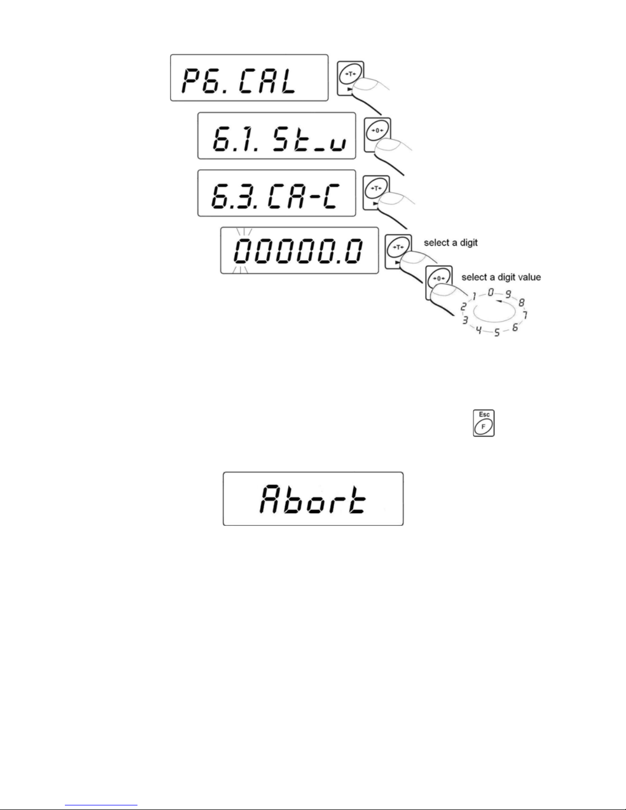
Procedure:
Enter the submenu <P6.CAL> and then:
- 55 -
Page 56
After completion of the calibration process program returns
to weighing mode.
x Calibration process can be terminated anytime by pressing
which is signalled by the following message on the display:
Notice:
1. It should be remembered that internal calibration should
be performed with unloaded pan with keeping possibly
constant ambient conditions.
2. If the calibration process lasts longer than 15 seconds scale
software will react with <Err8> displayed and a short sound
and then the calibration procedure will start again.
- 56 -
Page 57
17.2. External calibration
Option only for non-verified scales
Not accessible in WLC…/C/2 scales of WLC series
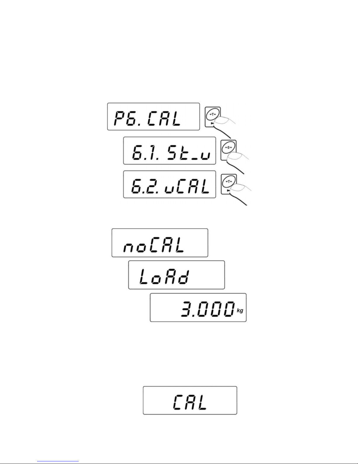
Procedure:
x Enter submenu <P6.CAL> and then:
x Following messages will be displayed:
x During this time start mass is adjusted, and after completing the
procedure calibration weight mass is displayed (e.g. 3.000kg),
x Place the required weight on the pan,
x Calibration process starts automatically after placing the
adequate weight that is signalled by the following message:
- 57 -
Page 58
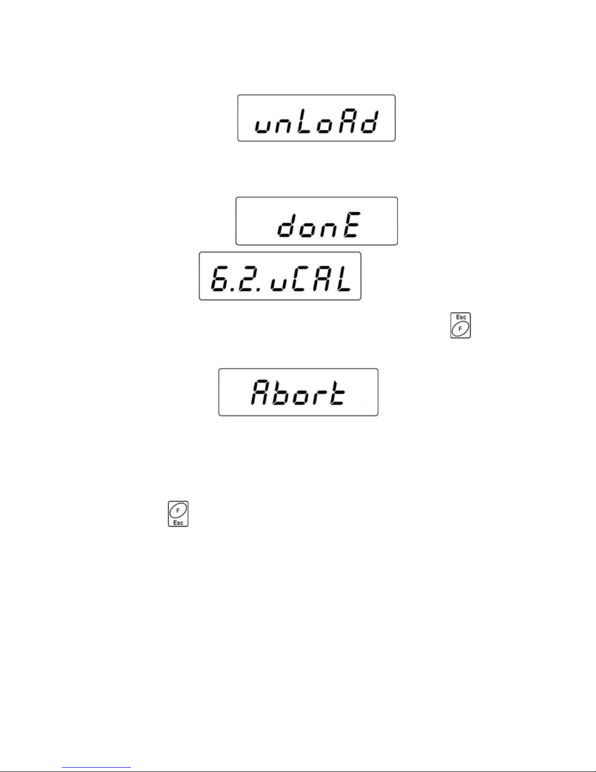
x The completion of the calibration procedure is signalled
by the following message:
x Take off the weight from the pan, the message <donE> is displayed
for 1s and the program returns to the calibration submenu:
x Calibration process can be terminated anytime by pressing
which is signalled by the following message on the display:
x Return to weighing with saving changes that have been made.
Caution:
If the calibration process (span adjustment) lasts longer than 15 the
<Err8> message will be displayed and short audible signal will be
emitted. Press
to perform calibration again with more stable
ambient conditions!
17.3. Start mass adjustment
Option only for non-verified scales
Not accessible in WLC…/C/2 scales of WLC series
The scale can require only adjusting new start mass. In this scale adjusting
start mass can be excluded from the process of calibration and performed
separately.
- 58 -
Page 59
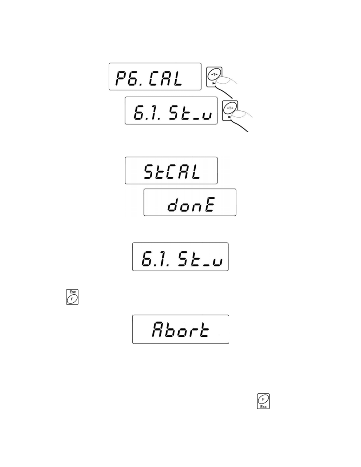
Procedure:
x Enter submenu <P6.CAL> and then:
x The following messages are displayed:
x The new start mass is adjusted and returns to the submenu:
x The process of start mass adjustment can be terminated by pressing
, which is signalled on the display:
x Return to weighing with saving changes that have been made.
Caution:
If the start mass adjustment lasts longer than 15 the <Err8> message will
be displayed and short audible signal will be emitted. Press
to perform
calibration again with more stable ambient conditions!
- 59 -
Page 60
18. COOPERATION WITH PRINTER
Each time the
key is pressed a current mass value together with
mass units is sent to RS 232 interface.
Depending on setting of STAB parameter it can be printed out with
temporary or stable value. Depending on setting of REPL parameter,
printout will be automatic or manual.
One of thermal printer in KAFKA series can cooperate with each
platform scales:
a) KAFKA
Only result of weighing with mass unit can be printed.
b) KAFKA 1/Z
This printer is equipped with an internal real time clock.
Both date and time can be printed.
c) KAFKA SQ S
This printer is equipped with an internal real time clock and
possibility of running statistics from measurements. Statistic
contents: quantity of samples, sum of masses of all samples,
average value, standard deviation, variation factor, min value,
max value, difference max - min.
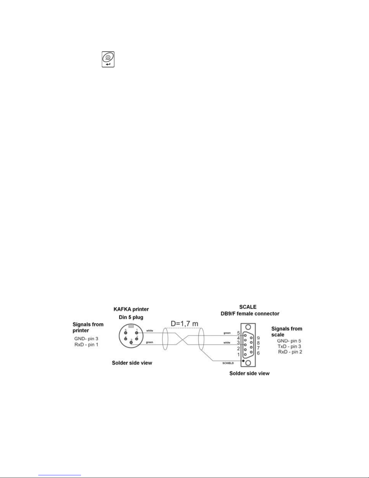
Cable diagrams:
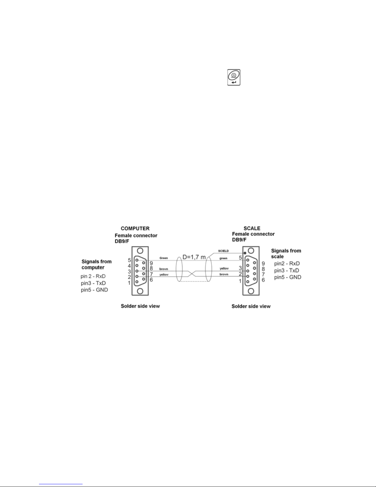
Scale – Kafka printer cable diagram
- 60 -
Page 61
19. COOPERATION WITH COMPUTER
Sending weighing results to the computer can be done:
- manually
- after pressing
key,
- in continuous way
- after function activating or sending
an appropriate command,
- automatically
- After stabilizing the indication
- on the request from
the computer
- After sending a control command
These scales can cooperate with „EDYTOR WAG” program. The indicator
window comprises the most important information from the scale display.
The program allows to configure easily, e.g. design printouts, edit
parameters. A precise description is issued in the „Help” file that
accompanies the program.
Cable diagrams:
Scale – computer cable diagram
- 61 -
Page 62

- 62 -
20. COMMUNICATION PROTOCOL
20.1. General information
A. A character protocol scale-terminal has been designed
for communication between RADWAG scales and external
devices via RS-232 interface.
B. It consists of commands sent from an external device to the
scale and a responses from a scale.
C. Responses are sent every time after receiving a command
(reaction for any command).
D. Using commands allows users to receive some information
about the state of scale and/or influence the operation e.g.:
x Requesting weighing results,
x Display control,
20.2. A set of commands for RS interfaces
Commands
Description of commands
Z
Zeroing
T
Tarring
S
Send the stable result in basic unit
SI
Send the result immediately in basic unit
SU
Send the stable result in current unit
SUI
Send the result immediately in current unit
C1
Switch on continuous transmission in basic unit
C0
Switch off continuous transmission in basic unit
CU1
Switch on continuous transmission in current unit
CU0
Switch off continuous transmission in current unit
PC
Send all implemented commands
Notice:
1. Each command have to be terminated in CR LF;
2. The best Policy for communication is not sending another
command until the former answer has been received.
Page 63

- 63 -
20.3. Respond message format
After sending a request message you can receive:
XX_A CR LF
command accepted and in progress
XX_D CR LF
command completed (appears only after XX_A)
XX_I CR LF
command comprehended but cannot be executed
XX _ ^ CR LF
command comprehended but time overflow error appeared
XX _ v CR LF
command comprehended but the indication below the
XX _ OK CR LF
Command done
ES_CR LF
Command not comprehended
XX _ E CR LF
error while executing command – time limit for stable result
exceeded (limit time is a descriptive parameter of the scale)
XX - command name
_ - substitutes spaces
20.4. Command’s description
20.4.1. Zeroing
Syntax Z CR LF
Possible answers:
Z_A CR LF
Z_D CR LF
- command accepted and in progress
- command completed
Z_A CR LF
Z_^ CR LF
- command accepted and in progress
- command comprehended but zero range overflow appeared
Z_A CR LF
Z_E CR LF
- command accepted and in progress
- time limit for stable result exceeded
Z_I CR LF
- command comprehended but cannot be executed
20.4.2. Tarring
Syntax: T CR LF
Possible answers:
T_A CR LF
T_D CR LF
- command accepted and in progress
- command completed
Page 64

- 64 -
T_A CR LF
T_v CR LF
- command accepted and in progress
- command comprehended but tare range overflow appeared
T_A CR LF
T_E CR LF
- command accepted and in progress
- time limit for stable result exceeded
T_I CR LF
- command comprehended but cannot be executed
20.4.3. Send the stable result in basic unit
Syntax: S CR LF
Possible answers:
S_A CR LF
S_E CR LF
- command accepted and in progress
- time limit for stable result exceeded
S_I CR LF
- command comprehended but cannot be executed
S_A CR LF
MASS FRAME
- command accepted and in progress
- mass value in basic unit is returned
Frame format:
1 2-3 4 5 6 7-15 16 17 18 19 20 21
S space stability space sign mass space unit CR LF
Example:
S CR LF – computer command
S _ A CR LF - command accepted and in progress
S _ _ _ _ - _ _ _ _ _ _ 8 . 5 _ g _ _ CR LF – command done, mass value
in basic unit is returned.
20.4.4. Send the result immediately in basic unit
Syntax: SI CR LF
Possible answers:
SI_I CR LF
- command comprehended but cannot be executed at the
moment
SI_A CR LF
MASS FRAME
- command accepted and in progress
- mass value in basic unit is returned
Page 65

- 65 -
Frame format:
1 2 3 4 5 6 7-15 16 17 18 19 20 21
S I space stability space sign mass space unit CR LF
Example:
S I CR LF – computer command
S I _ ? _ _ _ _ _ _ _ 1 8 . 5 _ k g _ CR LF - command done, mass value
in basic unit is returned immediately.
20.4.5. Send the stable result in current unit
Syntax: SU CR LF
Possible answers:
SU_A CR LF
SU_E CR LF
- command accepted and in progress
- timeout while waiting for stable results
SU_I CR LF
- command comprehended but cannot be executed
SU_A CR LF
MASS FRAME
- command accepted and in progress
- mass value in current unit is returned
Frame format:
1 2 3 4 5 6 7-15 16 17 18 19 20 21
S U space stability space sign mass space unit CR LF
Example:
S U CR LF – computer command
S U _ A CR LF - command accepted and in progress
S U _ _ _ - _ _ 1 7 2 . 1 3 5 _ N _ _ CR LF - command done, mass value
in current unit is returned.
20.4.6. Send the result immediately in current unit
Syntax: SUI CR LF
Possible answers:
Page 66
- 66 -
SUI_I CR LF
- command comprehended but cannot be executed
SUI_A CR LF
MASS FRAME
- command accepted and in progress
- mass value in current unit is returned immediately
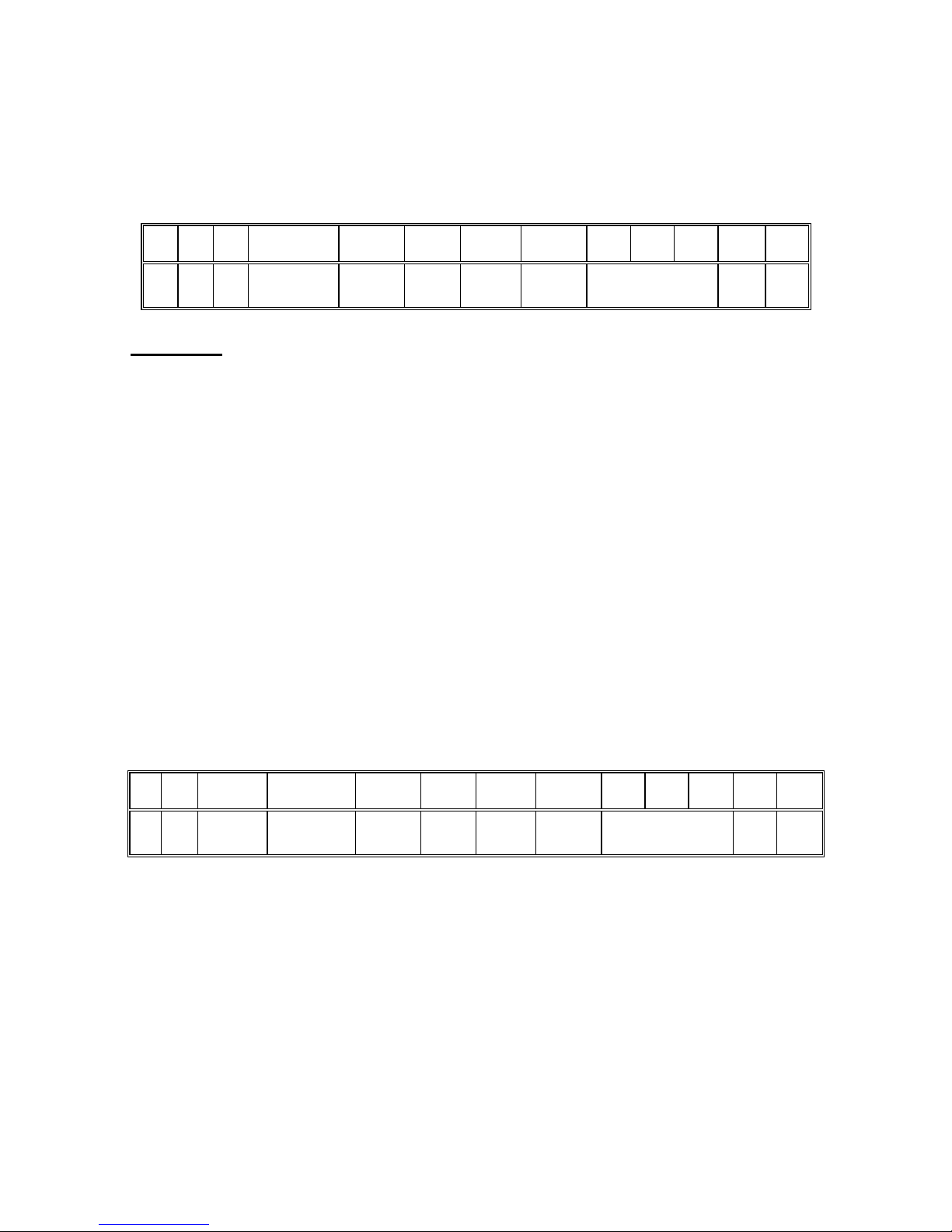
Frame format:
1 2 3 4 5 6 7-15 16 17 18 19 20 21
S U I stability space sign mass space unit CR LF
Example:
S U I CR LF – computer command
S U I ? _ - _ _ _ 5 8 . 2 3 7 _ k g _ CR LF - command executed and mass
returned
20.4.7. Switch on continuous transmission in basic unit
Syntax: C1 CR LF
Possible answers:
C1_I CR LF
- command comprehended but cannot be executed
C1_A CR LF
MASS FRAME
- command comprehended and in progress
- mass value in basic unit is returned
Frame format:
1 2 3 4 5 6 7-15 16 17 18 19 20 21
S I space stability space sign mass space unit CR LF
20.4.8. Switch off continuous transmission in basic unit
Syntax: C0 CR LF
Possible answers:
C0_I CR LF
- command comprehended but cannot be executed
C0_A CR LF
- command comprehended and executed
Page 67

- 67 -
20.4.9. Switch on continuous transmission in current unit
Syntax: CU1 CR LF
Possible answers:
CU1_I CR LF
- command comprehended but cannot be executed
CU1_A CR LF
MASS FRAME
- command comprehended and in progress
- mass value in current unit is returned
Frame format:
1 2 3 4 5 6 7-15 16 17 18 19 20 21
S U I stability space sign mass space unit CR LF
20.4.10. Switch off continuous transmission in current unit
Syntax: CU0 CR LF
Possible answers:
CU0_I CR LF
- command comprehended but cannot be executed
CU0_A CR LF
- command comprehended and executed
20.4.11. Send all implemented commands
Syntax: PC CR LF
Possible answers:
PC_- >_Z,T,S,SI,SU,SUI,C1,C0,CU1,CU0,PC – command executed,
the indicator have sent all the implemented commands.
Page 68
20.5. Manual printouts / automatic printouts
Users can general manual or automatic printouts from the scale.
x Manual printouts can be performed after loading the pan
and stabilizing indication by pressing
.
x Automatic printouts can be performed only after loading the pan
and stabilizing indication.
Notice:
If a scale is verified printouts of immediate values are blocked.
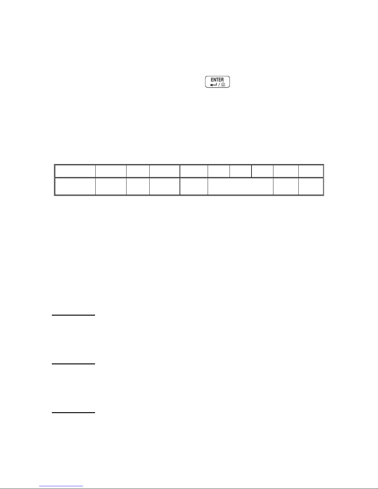
Format frame:
1 2 3 4 -12 13 14 15 16 17 18
stability space sign mass space unit CR LF
Stability character
[space] if stable
[?] if not stable
[^] if an indication over the range
[v] if fan indication below the range
sign
[space] for positive values or
[-] for negative values
mass
9 characters justified to the right
unit
3 characters justified to the left
command
3 characters justified to the left
Example 1:
_ _ _ _ _ _ 1 8 3 2 . 0 _ g _ _ CR LF – the printout generated from the
scale after pressing ENTER/PRINT.
Example 2:
? _ - _ _ _ _ 2 . 2 3 7 _ l b _ CR LF - the printout generated from
the scale after pressing ENTER/PRINT.
Example 3:
^ _ _ _ _ _ _ 0 . 0 0 0 _ k g _ CR LF - the printout generated from
the scale after pressing ENTER/PRINT.
- 68 -
Page 69
- 69 -
20.6. Continuous transmission
The indicator can work in a continuous transmission mode. It can
be switched on or off in parameters or using RS232 commands.
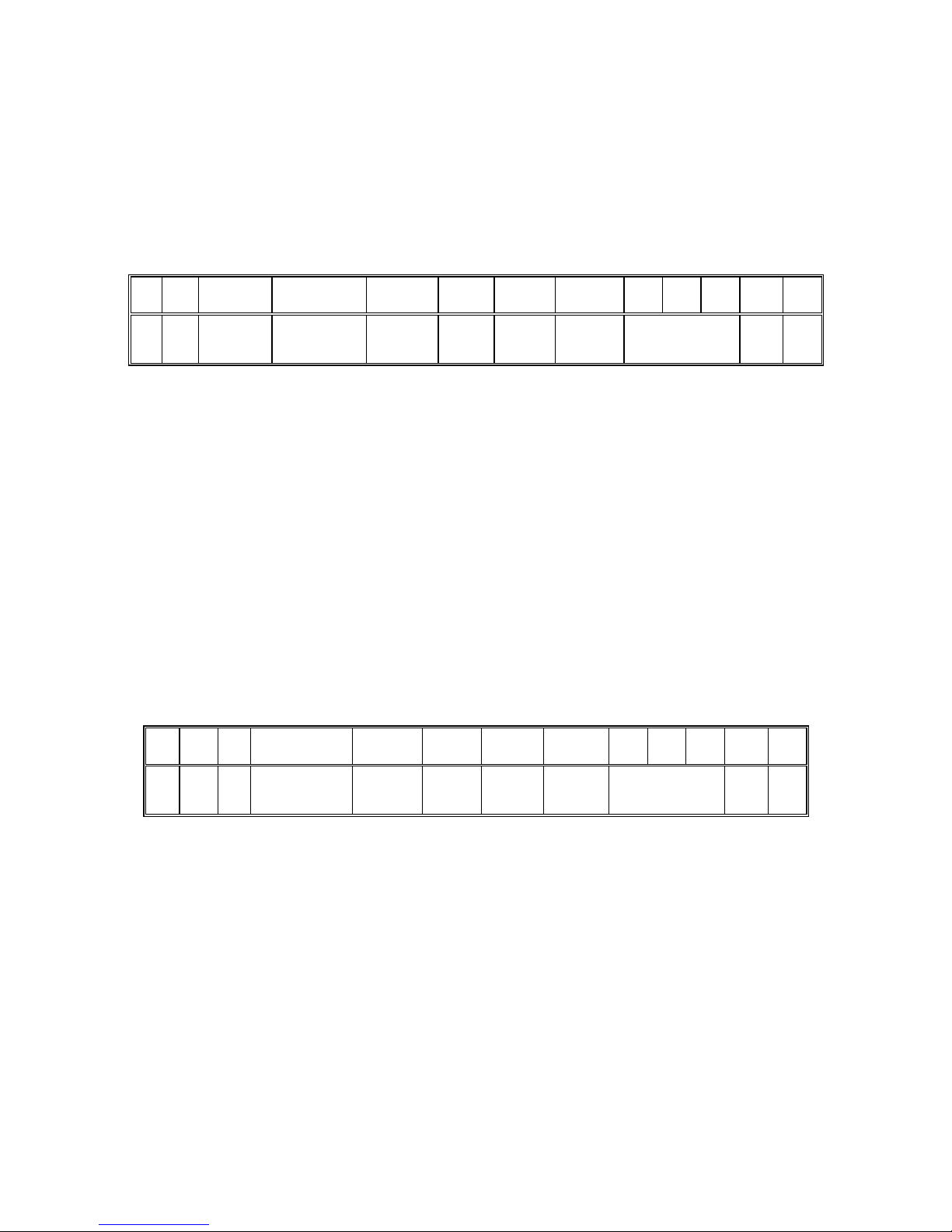
The frame format sent by the indicator in case of setting <P2.Prnt>
to CntA:
1 2 3 4 5 6 7-15 16 17 18 19 20 21
S I space stability space sign mass space Unit CR LF
Stability character
[space] if stable
[?] if not stable
[^] if an indication over the range
[v] if fan indication below the range
sign
[space] for positive values or
[-] for negative values
mass
9 characters justified to the right
unit
3 characters justified to the left
command
3 characters justified to the left
The frame format sent by the indicator in case of setting <P2.Prnt>
to Cntb:
1 2 3 4 5 6 7-15 16 17 18 19 20 21
S U I stability space sign mass space unit CR LF
20.7. Configuring printouts
General information
If some information included are redundant or not sufficient and there
is a necessity of changes one can design their own protocol format in
EDYTOR WAG computer program. This piece of software is accessible
in: http://www.radwag.com
Page 70

- 70 -
21. ERROR COMMANDS
Err2
- Value beyond the zero range
Err3
- Value beyond the tare range
Err4
- Calibration mass or start mass beyond the acceptable
range (r1% for weight, r10 for start mass)
Err5
- Mass of a single piece lower than the scale division
Err8
- Exceeded the time for tarring, zeroing, start mass
adjustment or span adjustment
NULL
- Zero value from the AD converter
FULL2
- Measurement range overflow
LH
- Start mass error, the mass on the weighing platform
is beyond the acceptable range r10 of start mass
5-FULL
- Display range overflow in totalizing
Notice:
1. Errors: Err2, Err3, Err4, Err5, Err8, null, that appear on the display
are also signalled by a short beep sound (about 1 sec.);
2. Error FULL2 that appears on the display is also signalled by
a continuous sound until the cause of error disappears.
22. TROUBLE SHOOTING
Problem Cause Solution
Discharged batteries
Connect to mains or
change batteries
Turning on does
not work
No batteries (not installed
or improperly installed)
Check the correctness of
installation (polarization)
The scale turns off
automatically
„t1” set to „YES”
(Power save)
In „othr” submenu change
„5.4 t1” to „no”
After turning on „LH”
message on the display
Loaded weight pan during
powering up
Unload pan. Then the
scale will indication zero
Page 71
- 71 -
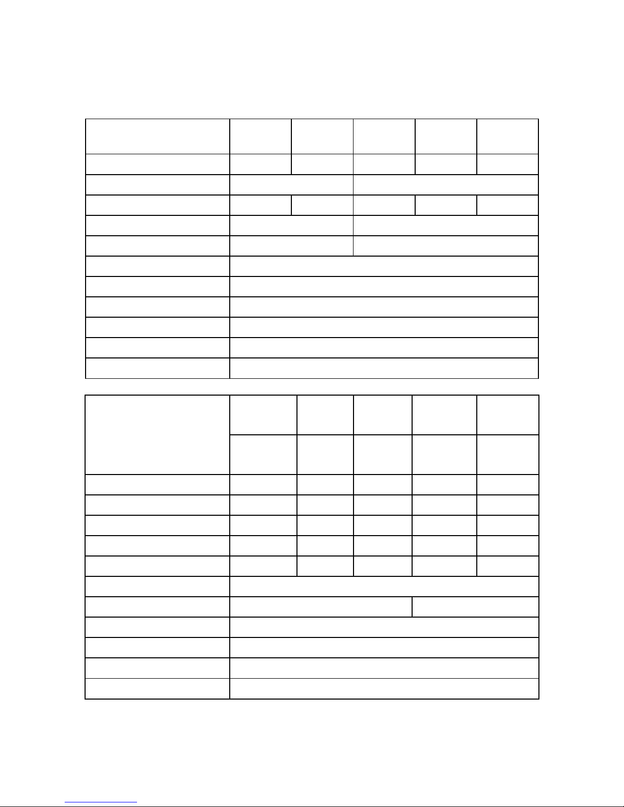
23. TECHNICAL PARAMETERS
23.1. Precisions scales of WLC series
Scale type:
WLC
1/A2
WLC
2/A2
WLC
6/A2
WLC
10/A2
WLC
20/A2
Max capacity 1kg 2kg 6kg 10kg 20kg
Readability 0,01g 0,1g
Range of tare -1kg -2kg -6kg -10kg -20kg
Repeatability 0,03g 0,3g
Linearity ±0,03g ±0,3g
Stabilization time 3 sec
Pan size 195 × 195mm
Operation temperature +15°C to +30°C
Supply 230V AC 50Hz / 11V AC, internal accumulator 6V
Supplied from batteries Average operation when supplied from batteries 45h
Display LCD (with backlight)
WLC 6
/C1/R
WLC 12
/C1/R
WLC 30
/C1/R
WLC 60
/C2/R
WLC 120
/C2/R
Scale type:
WLC 6
/C1/K
WLC12
/C1/K
WLC 30
/C1/K
WLC60
/C2/K
WLC 120
/C2/K
Max capacity 6kg 12kg 30kg 60kg 120kg
Readability 0,1g 0,2g 0,5g 1g 2g
Range of tare 6kg 12kg 30 kg 60 kg 120 kg
Repeatability 0,3g 0,6g 1,5g 3g 6g
Linearity ±0,3g ±0,6g ±1,5g ±3g ±6g
Stabilization time 3 sec
Pan size 290 × 360mm 400 × 500mm
Operation temperature +15°C to +30°C
Supply 230V AC 50Hz / 11V AC and 6×AA NiMH
Supplied from batteries Average operation when supplied from batteries 35h
Display LCD (with backlight)
Page 72
- 72 -
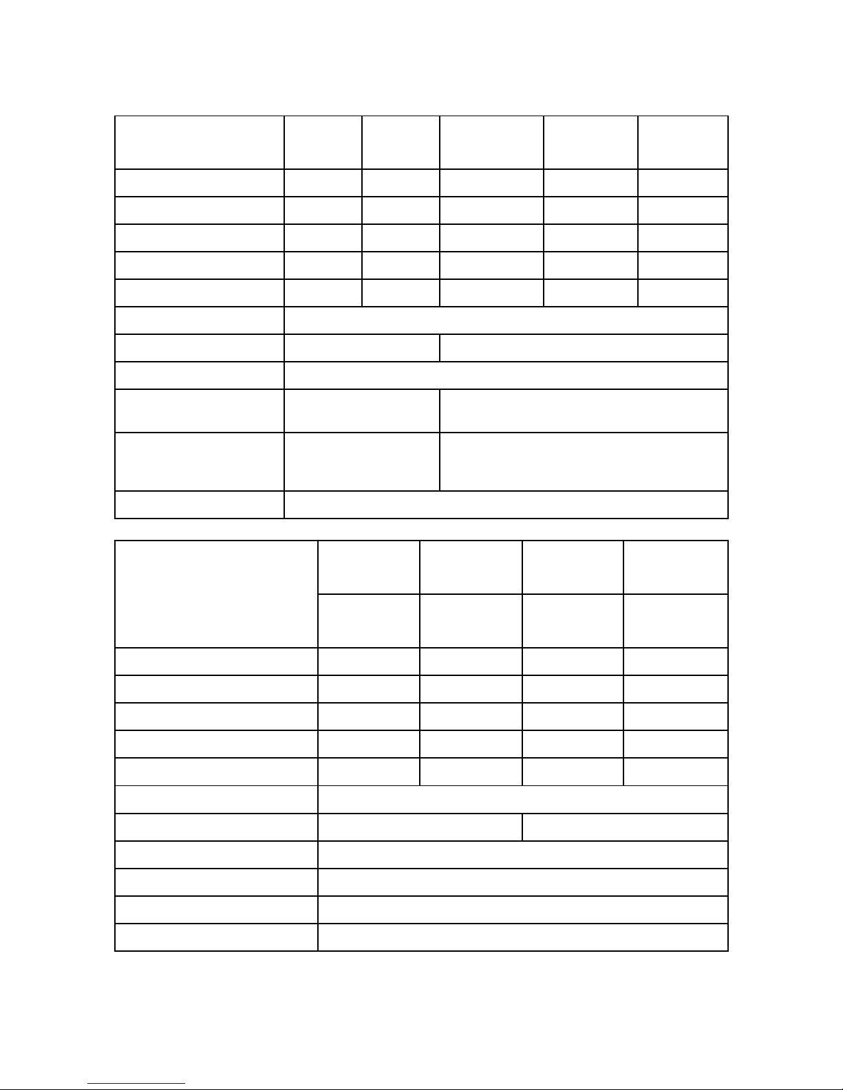
23.2. Verified precise scales of WLC series
Scale type:
WLC
0,6/B1
WLC
1,2/B1
WLC
1,2/3/A2
WLC
3/6/A2
WLC
6/12/A2
Max capacity 0,6kg 1,2kg 1,2/3kg 3/6kg 6/12kg
Readability 0,01g 0,02g 0,02/0,05g 0,05/0,1g 0,1/0,2g
Range of tare 0,6kg 1,2 kg 3 kg 6 kg 12kg
Repeatability 0,01g 0,02g 0,02/0,05g 0,05/0,1g 0,1/0,2g
Linearity ±0,01g ±0,02g ±0,02/0,05g ±0,05/0,1g ±0,1/0,2g
Stabilization time 3 sec
Pan size 125 x 145mm 195 x 195mm
Operation temperature +15°C to +30°C
Supply
230V AC 50Hz / 11V
AC and 6×AA NiMH
230V AC 50Hz / 11V AC,
internal accumulator 6V
Supplied from
batteries
Average operation
when supplied from
batteries 35h
Average operation when supplied
from batteries 45h
Display LCD (with backlight)
WLC 6/12
/C1/R
WLC 12/30
/C1/R
WLC 30/60
/C2/R
WLC 60/120
/C2/R
Scale type:
WLC 6/12
/C1/K
WLC 12/30
/C1/K
WLC 30/60
/C2/K
WLC 60/120
/C2/K
Max capacity 6/12kg 12/30kg 30/60kg 60/120 kg
Readability 0,1/0,2g 0,2/0,5g 0,5/1g 1/2 g
Range of tare -12kg -30kg -60kg -120 kg
Repeatability 0,1/0,2g 0,2/0,5g 0,5/1g 1/2 g
Linearity ±0,1/0,2g ±0,2/0,5g ±0,5/1g ±1/2 g
Stabilization time 3 sec
Pan size 290 × 360mm 400 × 500mm
Operation temperature +15°C to +30°C
Supply 230V AC 50Hz / 11V AC and 6×AA NiMH
Supplied from batteries Average operation when supplied from batteries 35h
Display LCD (with backlight)
Page 73
- 73 -
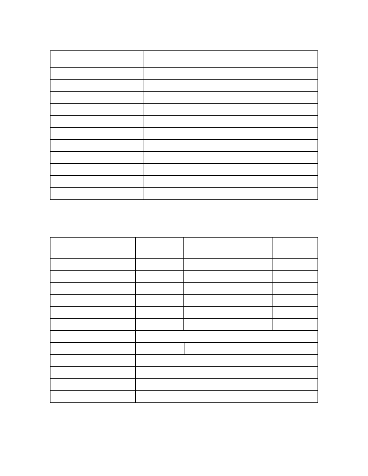
23.3. Precise scales of WLC…/C/2 series
Scale type: WLC 1/A2/C/2
Max capacity 1kg
Readability 0,01g
Range of tare -1kg
Repeatability 0,03g
Linearity ±0,03g
Stabilization time 3 sec
Pan size 195 × 195mm
Operation temperature +15°C to +30°C
Supply 230V AC 50Hz / 11V AC, internal accumulator 6V
Supplied from batteries Average operation when supplied from batteries 45h
Display LCD (with backlight)
23.4. Verified precise scales of WLC…/C/2 series
Scale type:
WLC
0,6/A1/C/2
WLC
1,2/A2/C/2
WLC
3/A2/C/2
WLC
6/A2/C/2
Max capacity 0,6kg 1,2kg 3kg 6kg
Min capacity 0,5g 1g 2,5g 5g
Readability 0,01g 0,02g 0,05g 0,1g
Repeatability 0,01g 0,02g 0,05g 0,1g
Linearity ±0,01g ±0,02g ±0,05g ±0,1g
Range of tare -0,6kg -1,2kg -3kg -6kg
Stabilization time 3 sec
Pan size 128 x 128mm 195 × 195mm
Operation temperature +15°C to +30°C
Supply 230V AC 50Hz / 11V AC, internal accumulator 6V
Supplied from batteries Average operation when supplied from batteries 45h
Display LCD (with backlight)
Page 74

- 74 -
24. ADDITIONAL EQUIPMENT
P0136 KAFKA printer cable for PUE C/31 indicators
P0151 EPSON printer cable
P0108 Computer cable
Page 75

- 75 -
 Loading...