

VETEC P1001, D100X Series Series Manual

Tel: +45 65919802
Fax: +45 65918802
post@vetec.dk
VETEC ApS, Lucernemarken 18
DK-5260 Odense, Denmark
http://www.vetec.dk
Serial Output option for the P1001 and D100X series
-232 RS232
-485 RS485 / RS422
Includes settings details for the Real Time Clock option -RTC
Software version F00.21
Document Ref:pm65\manuals\Serial Output Revision:4 Dated: 28 February 2011
1

.
Warranty
We warrant this product against defects in materials or workmanship for a period of three
(3) years from the date of purchase.
In the event of a defect during the warranty period, the unit should be returned, freight (and
all duties and taxes) prepaid by the Buyer to the authorised distributor from where the unit
was purchased.
The Distributor, at its option, will repair or replace the defective unit. The unit
will be returned to the Buyer with freight charges prepaid by the distributor.
LIMITATION OF WARRANTY
The foregoing warranty shall not apply to defects resulting from:
1. Improper or inadequate maintenance by the buyer.
2. Unauthorised modification or misuse.
3. Operation outside the environmental specification of the product.
4. Mishandling or abuse.
The warranty set forth above is exclusive and no other warranty, whether written or oral is
expressed or implied. We specifically disclaim the implied warranties of merchantability
and fitness for a particular purpose.
EXCLUSIVE REMEDIES
The remedies provided herein are the buyer’s sole and exclusive remedies.
In no event shall we be liable for direct, indirect, incidental or consequential damages
(including loss of profits) whether based on contract, tort or any other legal theory.
2

Warranty 2
General Description 4
Installation Hints 5
Serial Output board configuring 6
Setting up your serial port 7
Specifications 8
Modbus ASCII 9
Signal Levels 10
Fault finding 11
Contents
-RTC Real Time Clock option 12
-RTC Real Time Clock setup method 13
Notes 14
Notes 15
Connections and installing into a display See main display manual*
Record of revisions 16
* Need a manual urgently?
You can download manuals from our website
3
General Description
This manual only covers the setup of the serial output option. Please refer to the main display’s
operating manual for full specifications, installation methods, safety notices etc. You can
download manuals from our website.
The serial output option allows you to create an isolated RS232 or RS485 signal which provides
data proportional to the nett or gross value shown on the front of your display.
This can be used to feed remote devices such as data loggers, displays, PLCs and other
peripheral equipment.
There are 2 different option boards available:-
1. An RS232 board, for short distance point to point transfer of data
2. An RS485 board, which is suited for longer distance transmission and which may
be part of a group of addressed instruments.
Both boards can be set to transmit continuously or can be requested to transmit by a data
request.
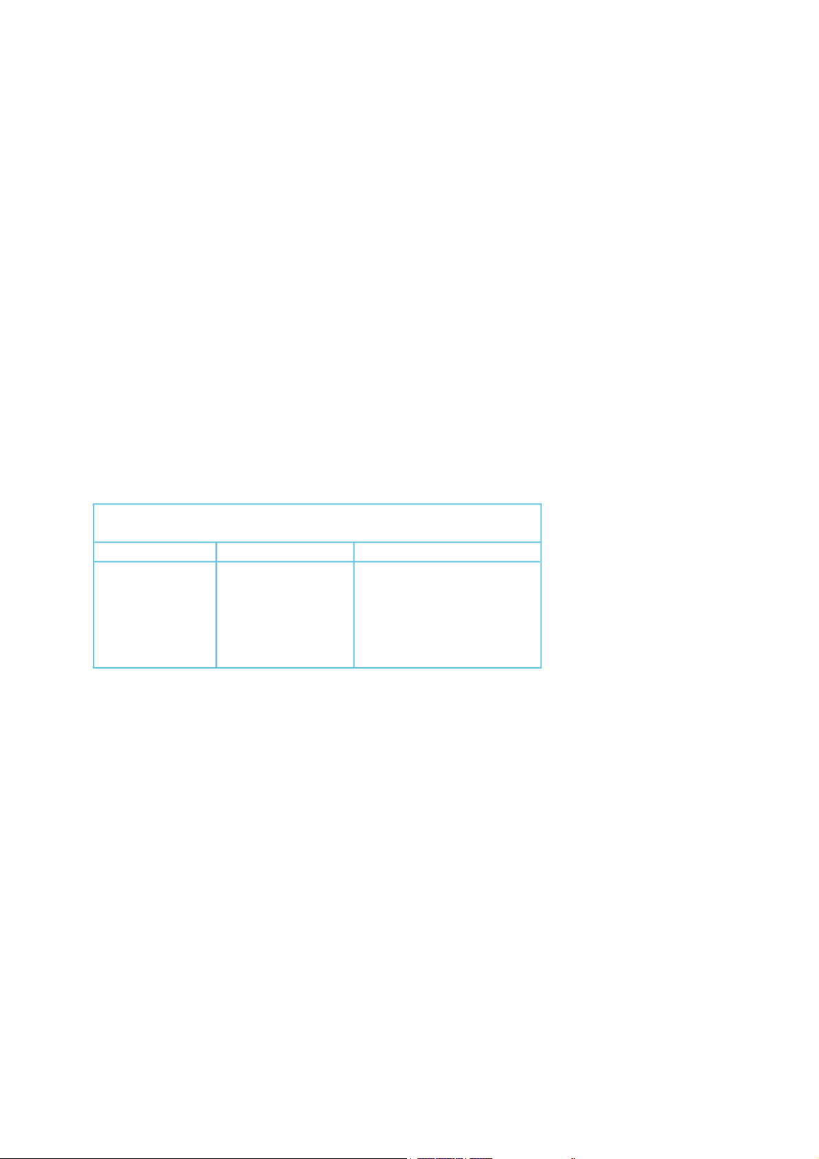
Maximum recommended cable distances if using LOW
capacitance screened cable such as CAT5 cable.
Baud Rate RS232 RS485 or RS422
1200 50m 1200m
9600 20m 150m
19200 10m 75m
38400 5m 30m
115200 2m 10m
The serial output is derived from the displayed value, so if you adjust filtering for the display,
the serial output will also be filtered and will respond to any input changes at the same speed
as the display.
The serial output is updated 10 times per second when in continuous mode.
4
Installation hints for best performance
This section offers several suggestions which will help you get the best performance from
your serial output.
1. Use good quality low capacitance twisted-pair screened signal cable. CAT5
screened twisted-pair is ideal.
2. The cable should be routed away from noisy wiring and devices such as power
feeds from inverters, discharge-lighting cables, welder cabling etc, and should
preferrably be routed in a dedicated low voltage signalling/instrumentation conduit
or cable tray.
3. Screened cable should be earthed at the destination end only.
4. All wires and screens coming out of the screened cable should be kept as short
as possible to minimise pickup of noise.
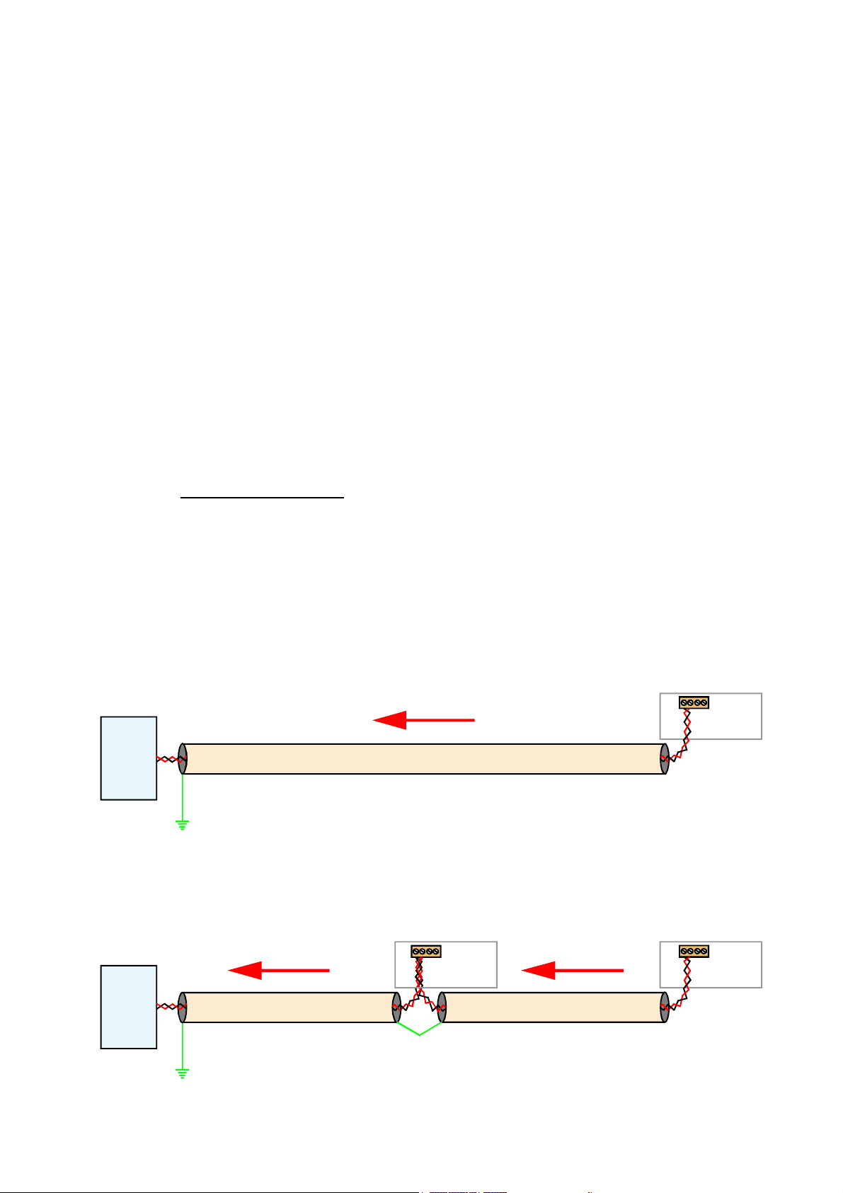
5. If you are going to daisy chain several RS485 devices together on the same data
line, you should earth your screen as shown below, paying particular care that you
do not earth both ends of any run of of cable.
6. Remember to fit a termination resistor to the instruments at each extreme end of
the cable run, but no termination resistor on intermediate units.
Receiver connection
With termination resistor
Remote
device
Connect screen
to earth ONLY
at this end.
Clean Earth
Receiver connection
With termination resistor
Length of screened cable
Polled
Output
NO termination
Display connections
Do not
connect
screen at
this end.
resistor
Display connections
Polled
Output
WITH termination
resistor
Polled
Output
WITH termination
resistor
Remote
device
Length of screened cable
Connect screen
to earth ONLY
at this end.
Clean Earth
Link Screen but do
not earth at this point.
Length of screened cable
Do not
connect
screen at
this end.
5
 Loading...