

Page 1
VESTIL MANUFACTURING CORPORATION
Revised 01-13
P.O. Box 507., Angola, IN 46703 USA
Phone (260) 665-7586 • Fax (260) 665-1339
E-mail: sales@vestil.com • www.vestil.com
Ergonomic Solutions
Revised 05-05 15-126-121
A company dedicated to solving ergonomic and material
handling problems since 1955
.
OWNER'S
MANUAL
TILT MASTER & TILT MASTER STRADDLE
MODELS TM / TMS
Contents
Warnings & Safety Instructions ....................... 1
Replacement Parts.......................................... 1
Receiving Instructions ..................................... 1
Operation Instructions .................................. 2-3
Routine Maintenance & Safety Checks ........... 4
TM Exploded Structural Parts ......................... 5
TM, TMS Bill of Materials ................................ 6
TMS Exploded Structural Parts ........................... 7
WARNINGS & SAFETY INSTRUCTIONS
Ensure that all employees understand and follow the
following.
• Read and understand the owner’s manual before using or
servicing the Tilt Master.
• For battery powered units, review the additional warnings
included in the “Operation Instructions” section of the
manual.
• Watch the container carefully when the tilter is in operation.
• Have the caster lock engaged solidly when the tilter is in
operation.
• Verify the container (not just the pallet) is fully back
against the fork carriage before tilting.
• Be alert of the possibility of parts falling from the container
when it is being tilted.
• Before transporting the container, raise the forks slightly.
• The load must be removed and the forks fully lowered
before any work is performed on the hydraulic system.
• Do not use the Tilt Master if damage or unusual noise is
observed.
• Do not perform any modifications to the Tilt Master without
the manufacturer’s approval. Failure to receive authorization for changes to the equipment could void the warranty.
• Maintenance and repairs are to be done only by personnel
qualified to perform the required work.
• Do not use brake fluid or jack oils in the hydraulic system.
If oil is needed, use an anti-wear hydraulic oil with a
viscosity grade of 150 SUS at 100° F, (ISO 32 cSt @ 40° ),
or Dexron transmission fluid.
• Ensure that safety and warning labels stay in place and
are legible.
• Use only replacement parts either supplied or
approved by the manufacturer.
Electrical Diagrams .......................................... 8
Motor & Transformer Diagrams ........................ 9
Hydraulic Diagrams ........................................ 10
Power Unit’s Operation .................................. 11
Modular Power Unit Breakdown - DC .......12-13
Modular Power Unit Breakdown - AC........ 14-15
Troubleshooting ............................................. 16
Safety Label Identification ......................... 17-18
Warranty......................................................... 19
WHEN ORDERING REPLACEMENT PARTS
We take pride in using quality parts on the equipment we
manufacture. We are not responsible for equipment problems
resulting from the use of unapproved replacement parts.
To order replacement or spare parts for this equipment,
contact the factory.
In any communication with the factory please be prepared to
provide the machine’s serial number, which is indicated on the
machine dataplate.
RECEIVING INSTRUCTIONS
Every unit is thoroughly tested and inspected prior to
shipment. However, it is possible that the unit could incur
damage during transit.
Inspect the unit closely when it arrives.
of damage or rough handling to either the packaging or to the
product when it is being unloaded,
it on the Bill Of Lading!
It is important that you remove the product’s packaging upon
its arrival to ensure that there is no concealed damage or to
enable a timely claim with the carrier for freight damage.
Also verify that the product and its specifications are as
ordered.
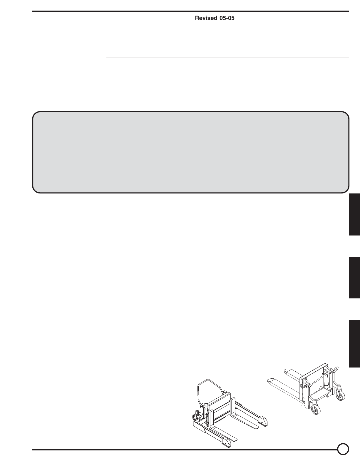
TM-SERIES Tilt Master
TMS-SERIES Tilt Master
STRADDLE
If you see evidence
immediately make a note of
1
E
N
G
L
I
S
H
E
S
P
A
N
O
L
F
R
A
N
Ç
A
I
S
Page 2

OPERATION INSTRUCTIONS – TM, TMS
•
Ensure that all employees involved in the operation of the Tilt Master model box/basket rotator understand and follow
these instructions!
The standard model Tilt Master is suitable for use indoors in most industrial locations. It is intended to be used to
transport, lift and rotate rigid, sturdy tote boxes or baskets containing nonhazardous materials so that they can be
gradually, manually unloaded. The model TM is intended for use only with open-bottom pallets or skids. The model TMS
can be used with either open- or closed-bottom pallets.
Loading:
The load rating, in pounds, is shown on the machine dataplate located on the top of the fork carriage. It indicates the
net capacity of the tilter, based on loads having a center of gravity not exceeding 20” horizontally and 20” vertically. The
load must be evenly distributed across both of the lifting forks.
Warning:
result from exceeding the listed capacity.
Warning:
the Tilt Master to become unstable and tip over.
Caution:
damage to the structure and its parts.
Note:
mining the maximum centers of gravity and working load that can be placed on the fork carriage.
To load the Tilt Master, fully lower the fork carriage. Push the tilter’s forks under the skid or container, or place the skid
or container on the forks with a fork truck, until the skid or container is back against the carriage. The forks can be raised
slightly to lift them off of the load rollers, and the load can be moved to the work location.
Do not exceed the load ratings stated above. Injury to personnel or permanent damage to the machine could
Tilting any load exceeding the 20” center of gravity rating (either horizontally or vertically) can potentially cause
Do not drop loads onto the Tilt Master’s forks. Shock loads to the carriage can cause premature wear and
The addition of any ancillary equipment to the Tilt Master by third parties must be taken into account when deter-
Operation:
When the Tilt Master is in the desired location, depress the pedal on the side of each swivel caster to prevent the tilter
from rolling during its operation.
Warning:
unit from rolling.
Warning:
Warning:
able to avoid being trapped or injured in the event there is an unexpected movement of the material or the machine.
Caution:
Warning:
The Tilt Master is furnished with a constant-pressure (dead-man style) push-button control.
Press the “UP” push-button to turn on the power unit to rotate the forks upward. The forks will rotate only while the
control is pressed. Upon releasing the control, the forks will stop and hold position.
Pressing the “DOWN” push-button energizes the lowering valve to allow the forks to rotate downward by gravity (the
motor does not run). Again, releasing the control will stop the forks’ movement, and the unit will hold its position.
Caution:
malfunctioning. Notify your supervisor or maintenance personnel if you notice anything out of the ordinary.
On DC-powered units, attempting to raise the carriage when the battery is low will cause the motor relay protection to
prevent the motor’s operation. Adequate battery voltage is indicated by a green LED on the motor relay. See the next
page for more notes regarding operation of battery-powered units.
Ensure that all safety and warning labels stay in place and are legible. Refer to the labels page in this manual.
Do not tilt loads more than two inches off the floor without the caster brakes properly engaged, to prevent the
Keep personnel clear of the machine when it is in operation.
Loads in containers can shift quickly when tilted. Always have an effective escape route for personnel to be
Always carefully watch the Tilt Master and any load on it when it is in operation.
Be certain no part of any person or object is under the forks or fork carriage before lowering the unit.
Never use the tilter if any damage or unusual noise is observed, if it is in need of repairs, or if it seems to be
2
Page 3

ADDITIONAL INSTRUCTIONS FOR BATTERY-POWERED UNITS
Note: If this product has the 24V powered traction-drive option, consult that option’s information for more
specific details regarding the batteries and battery charger.
Warning!
! Working with or near lead acid batteries is dangerous. Batteries contain sulfuric acid and produce explosive gases.
A battery explosion could result in loss of eyesight or serious burns.
! Do not smoke or allow a spark or flame near batteries. Charge batteries in locations that are clean, dry, and well
ventilated. Do not lay tools or anything metallic on top of any battery. All repairs to a battery must be made by
experienced and qualified personnel.
! When working with batteries, remove personal items such as rings, bracelets, necklaces, and watches. Batteries can
produce enough energy to weld jewelry to metal, causing a severe burn.
! Always have fresh water and soap nearby in case battery acid contacts skin, clothing, or eyes.
! Operating the battery with a low battery voltage can cause premature motor contact failure.
! Do not expose the tilter or charger to rain or adverse conditions.
! Replace defective cords or wires immediately.
! Check the battery’s water level frequently.
Battery Charger Operating Instructions
Never operate the charger with either of the cables coiled. Operating a battery charger with the cord either coiled or
wrapped around itself could cause the cord to overheat, melt, and cause a short-circuit or a fire.
Connection: the ribbed wire of the charger’s output cord must be connected to the battery’s negative (-) terminal. The
non-ribbed wire (with words printed on it) must be connected to the battery’s positive (+) terminal.
When properly connected, the charger will indicate the status of its output:
Flashing green LED – the charger is not seeing a good connection to the battery.
Solid yellow LED – the charger is providing charging current to the battery.
Solid green LED – the charger is maintaining a fully charged battery.
Plug the charger into a standard 115V receptacle. If an extension cord must be used, keep it as short as possible.
Caution:
cords, receptacles, and other equipment.
The battery charger can be left connected to the battery indefinitely without risk of harming the battery.
Remember to unplug the charger before moving the equipment. Failure to do so could cause damage to
E
N
G
L
I
S
H
Troubleshooting
If the unit does not operate, check all of the wiring connections to make sure they’re both mechanically and electrically sound – specifically at the battery, the motor, and at any location a wire is connected to the chassis. Also, make
sure the quick-connect plug on the end of the pendant control cord is plugged in correctly (if applicable).
A fully charged lead acid battery in good condition at room temperature should read 12.65 volts. At 11.9 volts it is
considered to be fully discharged and in need of charging. When checking battery voltage, wait at least 1/2 hour
after the charger has been turned off before checking the battery’s voltage.
If the batteries don’t seem to be taking a charge, check the charger’s 115V supply circuit and the charger’s output with a
voltmeter. If all check okay, confirm the battery’s state of charge using a hydrometer or a voltmeter.
3
Page 4

ROUTINE MAINTENANCE & SAFETY CHECKS – TM, TMS
•
Care should be taken to identify all potential hazards and comply with applicable safety procedures before beginning
work.
•
The load must be removed and the forks fully lowered before any work is performed on the hydraulic system.
•
Only qualified individuals trained to understand mechanical devices and their associated electrical and hydraulic
circuits should attempt troubleshooting and repair of this equipment
(A) Before each use inspect for the following:
1.) Frayed wires
2.) Oil leaks
3.) Pinched or chafed hoses
4.) Damage or structural deformation to the structural members, the cylinder brackets, etc.
5.) Unusual noise or binding, or evidence thereof.
6.) Proper functioning of the locking caster (to prevent wheel rotation).
7.) Proper functioning of all limits.
(B) In addition to the above, inspect monthly for:
1.) The oil level. Oil should be 1” to 1½” below the reservoir’s fill hole with the forks fully lowered.
2.) Worn or damaged hydraulic hoses and electrical wires.
3.) Pivot point wear at the hinge pins and cylinder ends.
4.) Intact pin and clevis retaining rings and / or fasteners.
5.) Looseness, wear, or damage to the casters’ bearings, mounting hardware, locking mechanism, or surface
material.
6.) Proper water level in the battery. (DC units.)
7.) Unusual noises.
8.) Information and warning labels being in place and in good condition.
9.) The need to clean off dirt and debris.
(C) Yearly inspection
The oil should be changed if the oil darkens, becomes gritty, or turns a milky color (indicating the presence of water).
Replace with an anti-wear hydraulic oil with a viscosity grade of 150 SUS at 100°F, (ISO 32 @ 40°C). Ex: AW 32 or HO
150 hydraulic fluid, or Dexron transmission fluid.
Ordering replacement parts:
We take pride in using quality parts on the equipment we manufacture. We are not responsible for equipment problems
resulting from the use of unapproved replacement parts.
Note: Motors, cylinders, and pumps can vary by model. Consult the manufacturer to determine the exact part numbers
for these items.
To order replacement or spare parts for this equipment, contact the manufacturer.
In any communication with the manufacturer, please be prepared to provide the machine’s serial number, which is
indicated on the machine dataplate.
4
Page 5
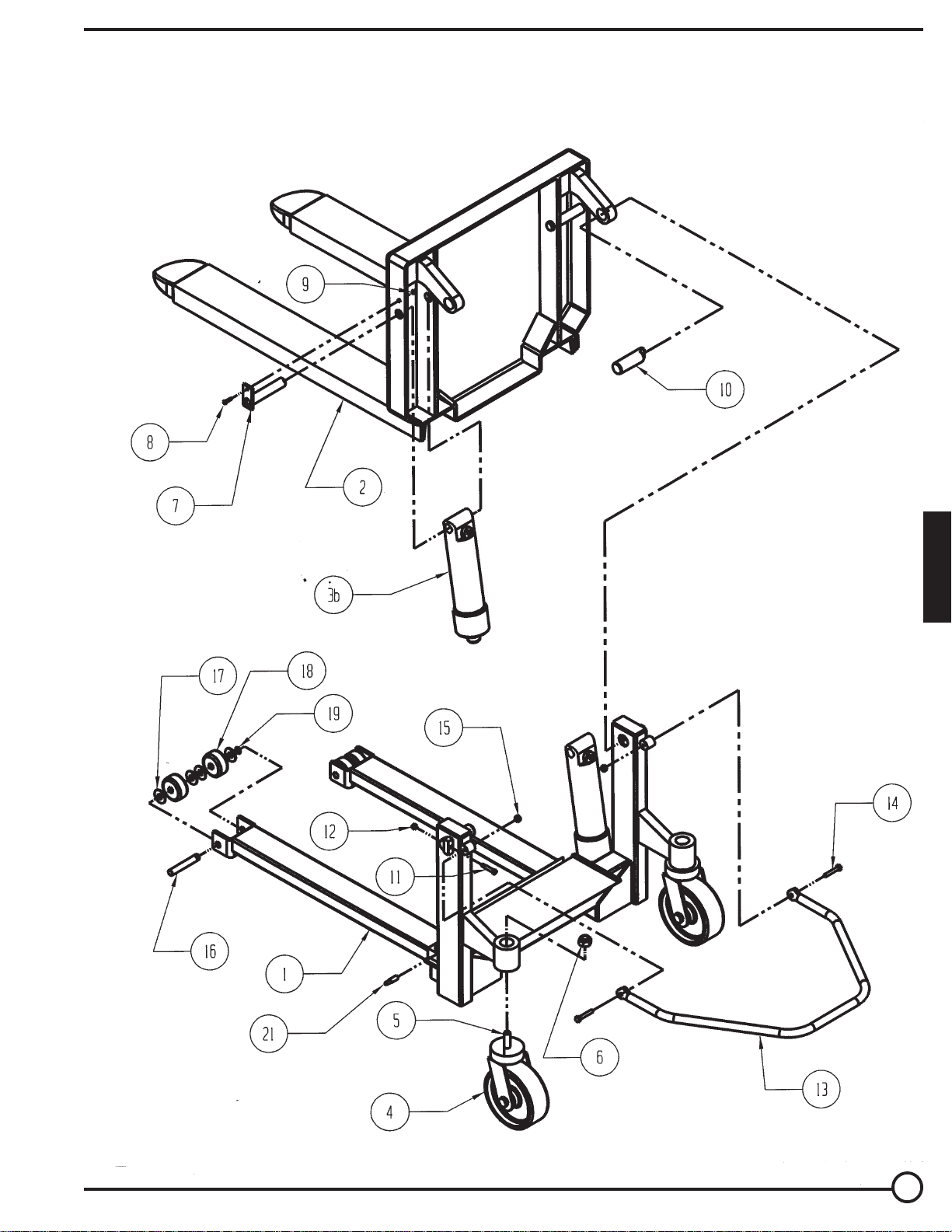
EXPLODED STRUCTURAL PARTS VIEW — TM
E
N
G
L
I
S
H
5
Page 6

BILL OF MATERIALS - TM
Item No.
1
2
3
4
5
6
7
8
9
10
11
12
13
14
15
16
17
18
19
20
21
Description
Frame weldment
Deck weldment
Cylinder, 3” x 10”, TM-60
Cylinder, 2-1/2” x 10”, TM-40
Cylinder, 2” x 10”, TM-20
Caster, Ø8” x 3” phenolic, swivel
olt, 3/4” -10 x 3 long
B
3/4” -10 jam top lock nut
Cylinder pin weldment
Bolt, 1/4” -20 x 1” long
Nut, 1/4” -20
Hinge pin weldment, Ø1 1/8” x 4”
Screw, self-tapping, 5/16” x 3/4” long
Cap, plastic, black
Push handle
Bolt, 3/8”-16 x 2-1/4” long
Nylock nut, 3/8” - 16
Roller pin, Ø3/4” x 4-3/4” long
Flat washer, 3/4” ID
Wheel, Ø3” x 1-1/2” wide phenolic
Snap ring, external, 3/4”
Limit switch, roller arm
Bolt, cylinder retaining, 1/2” -13 x 2” long
Part No.
38-514-033
38-513-006
99-021-901
99-021-906
99-021-914
PH-8/3-S-SWB-NTP
13365
37275
38-612-003
A/L
A/L
38-612-004
A/L
99-024-003
38-525-001
A/L
A/L
38-112-014
A/L
PH-3/1.5
A/L
01-022-001
01-118-001
Qty.
1
1
2
2
2
2
2
2
2
2
2
2
2
2
1
2
2
2
8
4
2
1
2
Item No.
1
2
3
4
5
6
7
8
9
10
11
12
13
14
15
16
17
18
19
20
21
BILL OF MATERIALS - TMS
Description
Frame weldment
Deck weldment
Handle assembly weldment
Bolt, 1/2” -13 x 2-1/4” long
Nylock nut, 1/2” -13
Hinge pin weldment, Ø1/8” x 4” long
Cap, plastic, black
Stem caster, Ø8” x 3” wide phenolic swivel
Bolt, 3/4” -10 x 3-1/4” long
Lock nut, 3/4” -10
Cylinder, 2” x 10”, TMS-20
Cylinder, 2-1/2” x 10”, TMS-40
Cylinder, 3” x 10”, TMS-60
Cylinder pin weldment
Bolt, 1/4” -20 x 1” long
Nut, 1/4” -20
Bolt, cylinder retaining, 1/2” -13 x 2” long
Wheel, Ø8” x 2” wide phenolic
Bolt, w/ grease zirk, 1/2” -13 x 3-1/2” long
Class II lifting fork, 36” long
Bolt, 3/8” -16 x 1” long, w/ 3/8” -16 lock nut
Screw, self-tapping, 5/16” x 3/4” long
Limit switch, roller arm (not shown)
Part No.
38-514-034
38-513-008
38-525-001
A/L
A/L
05-112-003
99-024-003
PH-8/3-S-SWB-NTP
A/L
A/L
99-021-914
99-021-906
99-021-901
38-612-003
A/L
A/L
01-118-001
PH-8/2-W
ZA2
15-028-007
A/L
A/L
01-022-001
Qty.
1
1
1
2
4
2
2
2
2
2
2
2
2
2
2
2
2
2
2
2
2
2
1
6
Page 7

EXPLODED STRUCTURAL PARTS VIEW — TMS
E
N
G
L
I
S
H
7
Page 8

Mobile Power Unit electrical system diagram, DC configuration (battery powered)
Mobile Power Unit electrical system diagram, AC configuration
Electrocution hazard: Disconnect the power cord from the energy source BEFORE opening/removing
the plastic housing. DO NOT modify the power unit.
Page 9

MOTOR & TRANSFORMER CONNECTION DIAGRAMS
Caution!
If the motor voltage is changed, the wire on the control transformer’s primary wire has to be changed to
match the new motor voltage also
E
N
G
L
I
S
H
9
Page 10

HYDRAULIC DIAGRAM – LIFT-HOLD-LOWER CIRCUITS
•
Warning: Care should be taken to identify all potential hazards and comply with applicable safety procedures before
beginning work. Fully lower or secure the forks, and ensure that all system pressure and power have been removed,
before attempting to work on the electrical or hydraulic systems.
•
Fully lower the unit before beginning any inspections or work.
•
Only qualified individuals trained to understand mechanical devices and their associated electrical and hydraulic
circuits should attempt troubleshooting and repair of this equipment
•
Caution: Do not use brake fluid or jack oils in the hydraulic system. If oil is needed, use an anti-wear hydraulic oil
with a viscosity of 150 SUS at 100°F (ISO 32 @ 40°C), or non-synthetic transmission fluid.
10
Page 11

THE POWER UNIT’S OPERATION – TM, TMS
The electric / hydraulic pallet tilter utilizes an electric motor directly coupled to a gear-type hydraulic pump to produce the
needed fluid pressure and flow to allow the cylinder(s) to perform the work of tilting a container.
A hydraulic manifold houses the hydraulic control components, and is bolted directly onto the gear pump.
The power unit’s hydraulic components are all rated for 3,000 psi working pressure.
• Important parts of the power unit include:
- The electric motor operates on 12 VDC deep-cycle battery supply.
- The gear pump. Its shaft is coupled directly to the shaft of the electric motor.
- The check valve. Its purpose is to prevent the backflow of fluid through the pump. In this way it allows the fork
carriage to be held at a given elevation indefinitely.
- The pressure relief valve. Its job is to open a path for fluid to flow back to the reservoir in the event that the fluid
pressure built up by the pump exceeds 3,000 psi. Thus the system cannot see more than 3,000 psi.
- The lowering solenoid valve. This is an electrically operated cartridge valve. It contains a screen to keep contaminants from entering the valve.
- The pressure-compensated flow control spool. This rests under the lowering valve, and regulates the fluid flow back
to the reservoir when the valve opens. It allows the forks to always lower at the same rate regardless of whether
there is a load on the fork carriage or not.
- The hydraulic tilt cylinder(s). These are displacement-style cylinders. They have a bleeder valve located at their top
end to allow air to be bled from the hydraulic system.
- The safety velocity fuse. This is a device that is installed in the cylinder’s hose port. It closes quickly in the event of a
catastrophic hose failure to prevent the fork carriage from collapsing down. The forks remain stationary until pressure is reapplied to the system.
- The hydraulic fluid. The system uses HO150 hydraulic fluid. Any anti-wear hydraulic fluid with a viscosity grade of
150 SUS at 100°F (ISO 32 @ 40°C) such as AW-32 or Dexron transmission fluid are acceptable.
When the forks are to be tilted, press the “UP” push-button. The motor turns, and in turning it spins the hydraulic
gear pump. Oil is drawn from the reservoir through the suction filter and into the pump. The pump pushes the thenpressurized oil through the check valve and out to the tilt cylinder(s).
When the fork carriage is to be lowered, press the “DOWN” push-button. The lowering valve opens, bypassing the
check valve and allowing the oil in the cylinder(s) to return back to the reservoir through the return hose. The rate at
which the fork carriage lowers is regulated by the internal pressure-compensated flow spool.
E
N
G
L
I
S
H
• In the event that the fork carriage creeps down slowly after releasing the “DOWN” control, it will be necessary to
remove the lowering cartridge valve for inspection and cleaning, as follows:
- Lower the forks until they are fully lowered.
- Remove any load from the forks.
- Remove the nut holding the solenoid coil on the valve stem, then remove the coil, and then unscrew the valve from
the manifold.
- Inspect the valve for contaminants, and the valve’s o-rings and backup washers for cuts, tears, or other damage.
- With the valve immersed in mineral spirits or kerosene, use a thin tool such as a small screwdriver or a small hex
wrench to push the poppet in and out several times from the bottom end of the valve. The valve should move freely,
about 1/16” from closed to open position. If it sticks in, the valve stem could be bent and will need to be replaced if it
doesn’t free up after cleaning. Blow the valve off with a compressed-air gun while again pushing the poppet in and
out.
- Inspect the bottom of the manifold’s valve cavity for contaminants.
- Again with the thin tool, press on the middle of the flow control spool located in the bottom of the cavity. It should
move down and back up freely.
- Reinstall the valve into the manifold, tightening the valve with approximately 20 lb-ft of torque.
• If the fork carriage lowers extremely slowly, or not at all, the cylinder’s velocity fuse could be closing. This can be
caused by air in the hydraulic cylinder(s). To bleed the air from the system:
- Lower the fork carriage until it is fully lowered.
- Remove any load from the forks.
- Hold a rag over the cylinder’s bleeder valve (it looks like a grease zirk) and open the valve about 1/2 turn with a 1/4”
or 5/16” wrench. Oil and air will sputter from the valve – once no air is observed, close the valve.
11
Page 12

Page 13

Page 14

MODULAR POWER UNIT PARTS BREAKDOWN — AC-1
Note: Motors, cylinders, and pumps can vary by model. Consult the manufacturer to determine the exact part numbers
for these items.
14
Page 15

MODULAR POWER UNIT PARTS BREAKDOWN — AC-2
•
Note: Motors, cylinders, and pumps can vary by model. Consult the manufacturer to determine the exact part
numbers for these items.
E
N
G
L
I
S
H
15
Page 16

TROUBLESHOOTING GUIDE — TM, TMS
Before performing any task, always lower the carriage fully to the floor and disconnect the power supply.
Consult the manufacturer for problems not addressed below.
* Check the DC notes page for troubleshooting other problems specific to battery-powered units.
Problem:
Power unit doesn’t run when “UP”
button is pressed.
Motor runs properly, carriage doesn’t
raise. Motor and pump not noisy.
Motor or control enclosure hums,
chatters, or buzzes, or some type of
squeal can be heard; the carriage
does not move, or the carriage
moves only slowly.
Carriage raises, then drifts down.
Carriage lowers too quickly.
Carriage lowers too slowly.
Carriage won’t lower.
Spongy or jerky carriage motion.
Possible cause(s):
No supply voltage (AC).
Upper-travel limit switch is engaged or
bad.
Bad connection in control circuit.
No control voltage (AC).
Bad motor relay coil.
Battery voltage low (DC).
Motor rotation is wrong (AC).
Pump has failed.
Fluid level is low.
See second item above, for when
carriage doesn’t raise.
Excess voltage drop to motor, due to
power wire size too small, wire run
too long, or incoming voltage too
low (AC).
Motor is “single-phasing” (AC).
Contamination holding open the
lowering valve or the check valve.
See last paragraph, above.
See above.
Flow control spool is stuck.
Flow control spool is stuck.
Pinched hose.
Velocity fuse locking (carriage only
slowly creeps down.)
Velocity fuse locking.
Control transformer (AC).
No supply voltage (AC).
Valve solenoid is bad.
Bad connection in control circuit.
Physical blockage of the structure.
Solenoid valve or suction hose screen
plugged.
Excessive air in the hydraulic
cylinders.
Action:
Test with meter. Check fuses,
breakers, and overloads to
determine the cause.
Inspect and test switch. Replace if
bad.
Test all circuits with meter.
Check for 24 VAC at control
transformer’s secondary; replace
fuse if blown.
Test with meter; replace if bad.
Test with meter. Charge battery if low
(is motor relay LED on?).
Verify motor shaft rotates CCW.
Consult factory for replacement.
Ensure reservoir is filled.
Same as above.
Check power installation for adequacy.
Check incoming voltage
is running
Determine cause of loss of voltage on
one phase; correct.
Remove and inspect. Clean per
instructions in this manual.
Same as above.
Same as above.
See below.
Remove plug from FC port; push on
flow spool to ensure it is fully
pressed into the cavity.
Check pressure, supply, and return
hoses for kinks.
Same as for jerky carriage motion.
Same as for jerky carriage motion.
Test with meter; replace if bad.
Check for 24 VAC at secondary;
replace fuse if blown.
Check with multimeter on diodecheck
function. (Reading for ohms will not
provide an accurate test of the coil.)
Test all of circuit with meter.
Inspect for foreign material or objects
blocking the carriage.
Remove and inspect. Clean per
instructions in this manual.
Bleed air per procedure described in
this manual.
. Correct problem found.
while motor
16
Page 17

SAFETY LABEL IDENTIFICATION
* Product safety signs or labels should be periodically inspected and cleaned by the product users as necessary to
maintain good legibility for safe viewing distance — ANSI 535.4 (10.21). Contact the manufacturer for replacement
labels.
1
RAISE
EL AUMENTO
AUGMENTATION
376
LOWER
MAS BAJO
PLUS BAS
377
MODEL TM
2
3
2
4
1
E
N
G
L
I
3
S
H
5
Inside on Reservoir
ISO 32 / 150 SUS
HYDRAULIC OIL OR HIGH-SYNTHETIC TRANSMISSION FLUID
ACEITE HIDRAULICO O LIQUIDOS DE TRANSMISION NO
SINTETICOS
HUILE OU LIQUIDE HYDRAULIQUE NON-SYNTHÉTIQUE
VESTIL MANUFACTURING CORPORATION • Phone (260) 665-7586 • www.vestil.com
Rev. 1003
6
7
Both Sides
VESTIL
MANUFACTURING
CORPORATION
Phone: (260) 665-7586
Fax: (260) 665-1339
E-mail: sales@vestil.com
www.vestil.com
580
206
8
8
Both Sides
4
5
6
7
17
Page 18

SAFETY LABEL IDENTIFICATION
* Product safety signs or labels should be periodically inspected and cleaned by the product users as necessary to
maintain good legibility for safe viewing distance — ANSI 535.4 (10.21). Contact the manufacturer for replacement
labels.
1
RAISE
EL AUMENTO
AUGMENTATION
376
LOWER
MAS BAJO
PLUS BAS
377
MODEL TMS
2
3
2
1
4
3
4
5
5
Inside on Reservoir
6
ISO 32 / 150 SUS
HYDRAULIC OIL OR HIGH-SYNTHETIC TRANSMISSION FLUID
ACEITE HIDRAULICO O LIQUIDOS DE TRANSMISION NO
SINTETICOS
HUILE OU LIQUIDE HYDRAULIQUE NON-SYNTHÉTIQUE
VESTIL MANUFACTURING CORPORATION • Phone (260) 665-7586 • www.vestil.com
6
7
Both Sides
VESTIL
MANUFACTURING
CORPORATION
Phone: (260) 665-7586
Fax: (260) 665-1339
E-mail: sales@vestil.com
www.vestil.com
18
580
Rev. 1003
206
8
7
8
Both Sides
Page 19

Rev. 01/2011
LIMITED WARRANTY
Vestil Manufacturing Corporation (“Vestil”) warrants this product to be free of defects in material and workmanship
during the warranty period. Our warranty obligation is to provide a
is covered by the warranty
, after we receive a proper request from the warrantee (you) for wa rranty service.
replacement for a defective original part, if the part
Who may request service?
Only a warrantee may request service. You are a warrantee if you purchased the product from Vestil or from an
authorized distributor AND Vestil has been fully paid.
What is an “original part”?
An original part is a part used to make the product as shipped
to the warrantee.
What is a “proper request”?
A request for warranty service is pr oper if Vestil receives: 1) a photocopy of the Customer Invoice
shipping date; AND 2) a written request
by any of the following methods:
for warranty service including your name and phone number. Send requests
that displays the
Mail Fax Email
Vestil Manufacturing Corporation (260) 665-1339 sales@vestil.com
2999 North Wayne Street, PO Box 507 Phone
Angola, IN 46703 (260) 665-7586
In the written request, list the parts believed to be defective and include the address where replacements should be
delivered.
What is covered under the warranty?
After Vestil receives your request for warranty service, an authorized representative will contact you to determine
whether your claim is covered by the warranty. Before providing warranty service, Vestil may require you to send the
entire product, or just the defective part or parts, to its facility in Angola, IN. The warranty covers defects in the
following original dynamic components: motors, hydraulic pumps, electronic controllers, switches and cylinders. It
also covers defects in original parts that wear under normal usage conditions (“wearing parts”): bearings, hoses,
wheels, seals, brushes, batteries, and the battery charger.
How long is the warranty period?
The warranty period for original dynamic components is 1 year
. For wearing parts, the warranty period is 90 days.
Both warranty periods begin on the date when Vestil ships the product to the warrantee. If the product was purchased
from an authorized distributor, the periods began when the distributor shipped the product. Vestil may extend the
warranty period for products shipped from authorized distributors by up to 30 days to account for shipping time.
If a defective part is covered by the warranty, what will Vestil do to correct the problem?
Vestil will provide an appropriate replacement for any covered part. An authorized representative of Vestil will contact
you to discuss your claim.
What is not covered by the warranty?
1. Labor;
2. Freight;
3. Occurrence of any of the following, which automatically voids the warranty
:
Product misuse;
Negligent operation or repair;
Corrosion or use in corrosive conditions;
Inadequate or improper maintenance;
Damage sustained during shipping;
Accidents involving the product;
Unauthorized modifications
: DO NOT modify the product IN ANY WAY without first receiving
written authorization from Vestil. Modification(s) might make the product unsafe to use or might
cause excessive and/or abnormal wear.
Do any other warranties apply to the product?
Vestil Manufacturing Corp. makes no other express warranties. All implied warranties are disclaimed to the extent
allowed by law. Any implied warranty not disclaimed is limited in scope to the terms of this Limited Warranty.
 Loading...