

Page 1
10/21/2010 rev. 10/22/2010 FTLP manual, operation instructions.doc
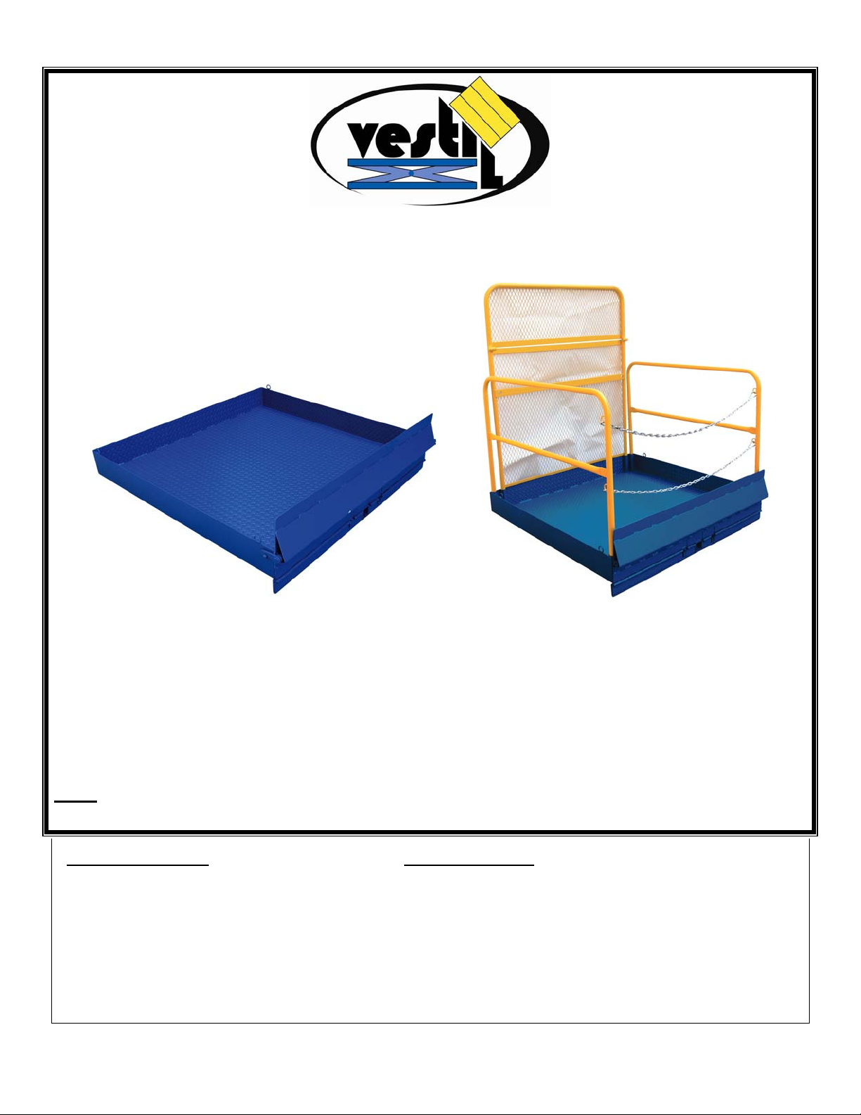
FTLP-SERIES EQUIPMENT PLATFORMS
INSTRUCTION MANUAL
MODEL: FTLP-5454 FTLP-5454-HR
MAXIMUM RATED LOAD: 2,000LBS (~909KG) 2,000LBS (~909KG)
VESTIL MANUFACTURING CORP.
2999 NORTH WAYNE STREET, P.O. BOX 507, ANGOLA, IN 46703
TELEPHONE: (260) 665-7586 -OR- TOLL FREE (800) 348-0868
FAX: (260) 665-1339
URL: WWW.VESTILMFG.COM EMAIL: SALES@VESTIL.COM
NOTE: Compliance with regulatio ns, codes, and/or statu tory (non-voluntary) standards enf orced in the
location where the platform is used is exclusively the responsibility of the end-user.
Table of Contents Table of Figures
Product Introduction………………………... 2 Fig. 1 “FTLP-series Exploded Parts Diagram & Parts List”….. 4
Safety Principles……………………............. 2 Fig. 2A “FTLP-5454 Center of Gravity Diagram”…………….. 5
Safety Guidelines…………………............... 3 Fig. 2B “FTLP-5454-HR Center of Gravity Diagram”…..…….. 5
Inspections & Maintenance………………… 3 - 4 Fig. 3 “Mast Guard Hinge”……………..………………...……… 6
Loading and Using the Platform…………… 6 - 7 Fig. 4 “Proper Attachment of Safety Strap to Carriage”……… 6
Fig. 5 “Safety Strap Attachment to Platform”…………...…....... 6
Fig. 6 “Anchorage Points”……………………………………….. 7
Fig. 7 “Ramp Closure Mechanism”……………………………. 7
Fig. 8 “Product Markings and Labels”…………………………. 8
Copyright 2010 Vestil Manufacturing Corp.
Page 2
10/21/2010 rev. 10/22/2010 FTLP manual, operation instructions.doc
PRODUCT INTRODUCTION
Standard design features i nclude: fork pocket s that rece ive the tines (forks) of a fo rk lift; loading ramp; t oeboards;
textured flo or plate fo r improved tractions; and a safety chain to secure the work platform to the fork carriage to prevent
the platform from sliding off of the forks if the lift operator accidentally tilts the m ast forward during use. Optional features
include: mast guard; gu ard rails; and e ntryway-spanning chains. Dimensions and other p roduct sp ecifications appear in
the following table:
Model
FTLP-5454 54 x 54 (137 x 137)cm 7½ x 2½ (19 x 6.4)cm 2,000 (909kg) 300 (136kg)
FTLP-5454-HR* 54 x 54 (137 x 137)cm 7½ x 2 ½ (19 x 6.4)cm 2,000 (909kg) 410 (186kg)
*Includes removable handrails (2), entryway chains (2), and expanded metal mast guard.
: To ca lculate the weight of a “ful ly loaded platform,” select the sp ecific model you own/use, find the net weight of
NOTE
your model in the table above, and then add 2,000 pounds (909kg).
Platform dimensions
width x length in
Thank you f or p urchasing a fork-mou ntable e quipment loadi ng platform (“platform” or
“loading pl atform”) m ade
by Vestil Ma nufacturing Corporation (“Vestil”). Our platform s a re
durable, high-quality products that combine safety-features and reliable mechanics. Altho ugh
use and m aintenance p rocedures are relatively intuitive, all person s who might use o r
maintain this product must familiarize themselves with the instructions provided in this manual.
inches (~cm)
Fork pocket dimensions
width x height in inches
(~cm)
Uniform maximum
rated load in pounds
(kg)
Net weight in
pounds (~kg)
Safety Principles
Vestil Manufacturing Corp. recognizes the critical im portance of workplace safety. Howeve r, although Vestil diligently
strives to ide ntify foreseeable hazardous situations, this manual cannot a ddress every conceivable danger. The end-user
is ultimately responsible for exercising sound judgment at all times.
This m anual will acquai nt person s au thorized to u se a nd/or maintain this equipment pla tform with sa fe use a nd
maintenance pro cedures. Each person, who might use or perform maintenance on the equipment platform, must
read and understand every instruction BEFORE using the device or performing maintenance. Users sh ould have
access to the manual at all times and should routinely review the directions.
Employers are responsible for training employees to use the product properly. If you do not understand an instruction,
ask yo ur su pervisor or emp loyer for assistance, be cause fa ilure to follo w th e directio ns i n this m anual might result in
serious personal injury or even death.
Vestil is not liable for a ny injury o r property damage that occu rs as a consequence of faili ng to ap ply e ither: 1) th e
instructions that appear in this manual; or 2) the information provided on labels affixed to the product. Furthermore, failure
to exercise good judgment and comm on sense might result in property damage, serious personal injury or death. Such
failure is solely the fault of the person(s) using the equipment platform.
This manual uses SIGNAL WORDS to classify personal injury risks and situations that might lead to property damage,
as well a s to draw attenti on to safety messag e(s). The reader must und erstand that eac h signal word indicate s the
seriousness of the described hazard.
Identifies a hazardous situation which, if not avoided, WILL result in DEATH or SERIOUS
Identifies a hazardous situation which, if not avoided, COULD result in DEATH or SERIOUS
Indicates a hazardous situation which, if not avoided, COULD result in MINOR or MODERATE
Identifies practices likely to result in product/property damage, such as operation that might damage the
INJURY. Use of this signal word is limited to the most extreme situations.
INJURY.
injury.
equipment platform.
Copyright 2010 Vestil Manufacturing Corp.
p. 2 of 9
Page 3
10/21/2010 rev. 10/22/2010 FTLP manual, operation instructions.doc
SAFETY GUIDELINES
Study the entire manual before you use the product for the first time and before each subsequent use
Failure to read and understand the instructions included in this manual before
using or servicing the work platform constitutes misuse of the product.
. Read the
manual to re fresh you r u nderstanding of the safe use, in spection an d mai ntenance procedures explai ned o n p. 5. If
questions re main about the product after you fini sh rea ding the manual, contact Vestil for answers. DO NOT attem pt to
resolve any problems with the work platform unless you are authorized to do so and are certain
afterwards.
that it will be safe to use
Electrocution might result if the platform contacts electrified wires. Reduce the likelihood of electrocution by
applying common sense:
DO NOT contact electrified wires with any part of the platform;
DO NOT use the platform in an area where contact with electrified wires is likely;
DO NOT use the platform close to electrified wires or other sources of electricity;
Before using the platform, always inspect the usage area for unusual conditions that require special precautions.
Material ha ndling i s dangerous. Improper or carel ess ope ration might result in se rious pe rsonal inju ries
sustained by the fork truck ope rator, platform occupant, and/or bystanders. Apply to the foll owing suggestions to reduce
the likelihood of injury (unless law compels different action(s)):
Contact the manufacturer of your lift truck to verify that the truck is ca pable of safely handling the fully loaded platfo rm.
To calculate t he weight of a “fully loa ded platform,” select the specific model y ou own/use, find the net weight of you r
model in th e table above, and then add 2,000 pounds (9 09kg). The width of your pl atform must be equal to or le ss
than the width of your fork truck plus 10 inches (250mm).
ONLY use the platform as a means for lifting and transporting equipment NOT people.
DO NOT use a structurally compromised platform. Examples of structural damage includes: broken/severely damaged
railings, mast guard, or fork pockets, and holes produced by rust or corrosion in the platform floor. Inspect the platform
before ea ch use according to the inspection instructions on p. 3-4. DO NOT use the platform unle ss it passes every
part of the inspection.
DO NOT use the platform if the safe ty strap i s d amaged or missing; DO NOT lift the platform u ntil it is se curely
connected to the carriage of the fork truck with the safety strap (see Step 1 & 2 on p. 6).
DO NOT attempt to lift a load that wei ghs more than the maximum load rating of the platform. The net wei ght, i.e. the
combined weight of everything supported by the platform including any person supported by the platform while loading
or unloading equipment, cannot exceed the maximum rated load of the platform.
DO NOT stand beneath or travel under the platform while it is elevated.
DO NOT use the chains, mast guard, or guardrails as a step.
DO NOT use the platform to transport people! A person should only stand o r walk on the p latform to load and unload
equipment.
DO NOT use the platform UNLESS each l abel shown i n Fi g. 8 on p. 8 is affixed to the platform, undamaged and
readable.
Inspections & Maintenance
Before each use inspect the listed components:
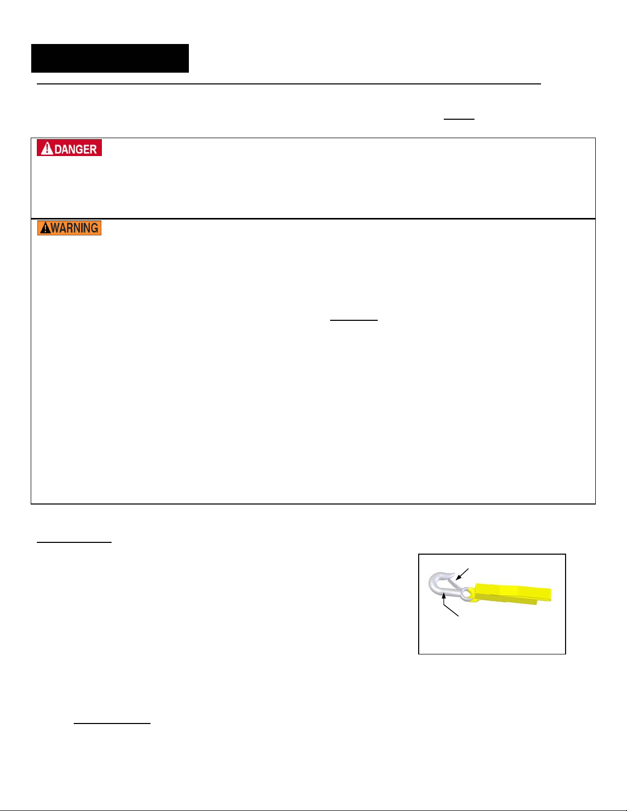
1. Snap hook (attached to th e free en d of the nylon sa fety strap): confirm that
the sp ring latch a utomatically closes securely against the tip of the hoo k as
shown in the diag ram to the rig ht. If the h ook, n ylon strap, o r latch i s
spring
latch
damaged, th en do not use the platfo rm until a complete, ne w safety strap i s
obtained an d attach ed to the platfo rm. Refer to steps 1 & 2 o n p. 6 fo r
attachment procedures.
2. [FTLP-54 54-HR] Handrails: che
ck the rails, rail wel ds, and poi nts of conta ct
between the rails and t he sl eeves welded to th e platform f or be nding,
warping and cracking.
hook
Nylon safety strap (item no. 1
on p. 4)
3. [FTLP-54 54-HR] Lanyard attachment points: check the anchorage weldment
(see FIG. 6 on p. 7) and points of attachment to the mast guard for bending,
warping, or cracking.
4. Product labels: all labels should be readable and located as shown in the diagram on p. 8. If a label(s) is unreadable
or missing, contact Vestil to order a replacement.
At least 1 time per month, inspect:
1. Fasteners (hardware):
Mast guard hinge - bolts, nuts, washers. Replace all damaged fasteners.
Gate – chains, sn ap hooks, welded D-rings (attachment point s for each chain ). DO NOT use the platform
until all damaged hooks and chains are replaced and damaged D-rings are restored to original condition.
Copyright 2010 Vestil Manufacturing Corp.
p. 3 of 9
Page 4

10/21/2010 rev. 10/22/2010 FTLP manual, operation instructions.doc
2. Fork pockets: confirm that each pocket is structurally sound, not corroded or rusted. DO NOT use the platform if the
fork pockets are structurally compromised or dangerously rusted or corroded.
3. Welds: confirm that all welds are intact . DO NOT u se the platform if authorized mainten ance p ersonnel determine
that a damaged weld compromises the soundness of the platform.
4. Barriers: inspect handrails, mast guard, and entryway chains for obvious damage or deformation.
5. (Overall con dition of) Pla tform: the structure should be clean, squ are and rigid, and fre e of ru st an d co rrosion.
Remove dirt and debris. DO NOT use the platform if the base is rusted or corroded.
FIG. 1: FTLP-SERIES EXPLODED PARTS DIAGRAM AND PARTS LIST
7
Item no. 2
Item
* = Optional features usable with FTLP-5454-HR platform &
Description Part No. Quantity
No.
Nylon safety strap and hook
1
2 5/16in. quick link 45214 1
3 3/16in. x 9in. chain 08-145-007 1
*4 Mast guard 14-514-134 1
*5 ¼ in. spring hook 0500499 4
*6 ¼ in. x 60in. chain 99-145-036 2
Platform & ramp weldment:
7
*8 Handrail 14-524-001 2
ramp weldment.
FTLP-5454
FTLP-5454-HR
08-145-027
14-513-011
14-513-012
1
1
1
Copyright 2010 Vestil Manufacturing Corp.
p. 4 of 9
Page 5

10/21/2010 rev. 10/22/2010 FTLP manual, operation instructions.doc
A
A
FIG. 2A: FTLP-5454 Center of Gravity Diagram
Model
FTLP-5454 32in. (~81¼ cm) 0.8in. (~2cm)
A: Horizontal
Center of Gravity
B: Vertical Center
of Gravity
Horizontal center of gravity (B)
measured f rom back of toe
guard
B
Lanyard attachment points
Mast
guard
Vertical cente r of
gravity (A ) cal culated
from bottom of platform
floor
center of gravity
(C.O.G.)
WP-series
FIG. 2B: FTLP-5454-HR Center of Gravity Diagram
Model
A: Horizontal Center
of Gravity
FTLP-5454-HR 25.3in. (~64.3cm) 11.3in. (~28.7cm)
B: Vertical Center
of Gravity
Vertical cente r of
gravity (A ) cal culated
from bottom of platform
floor
Copyright 2010 Vestil Manufacturing Corp.
p. 5 of 9
B
Horizontal cente r of g ravity (B )
measured fr om back of mast
guard
Page 6

10/21/2010 rev. 10/22/2010 FTLP manual, operation instructions.doc
t
Fig. 3: Mast Guard Hinge
Upper mast guard
Lower mast
guard
lower portio ns of the ma st guard are
improperly fa stened, the g uard cannot
adequately protect platform occupants.
Therefore, make sure that hing e
fasteners (circled i n the d rawings) are
tightened t o 35ft·lb of torque.
Retighten the connection to 35 ft·lb
whenever:
1. The work pla tform is take n out of
storage:
Raise th e u pper po rtion of the
mast guard, and then
Hex
nut
Bol
Tighten the bolts and nuts.
2. If the mast guard is b umped (or
deflected from vertical):
Immediately lower the pl atform to
the ground; then
Straighten the mast guard (return
Close-up of con
between to p and bott om
nection
it to the ve rtical orientation) a nd
retighten the bolts and nuts.
portions of mast guard.
If the upper an d
Loading and using the platform:
Step 1: Mount the platform on the forks of your lift truck.
Drive the fork truck forwa rd until the toe guard (or mast guard
for FTLP-5454-HR) contacts the back (vertical part) of the tines.
Step 2: Fasten the nylon safety strap to the fork carriage.
T he n ylon s trap is an es sential s afetyenhancing fe ature. If the forks a re accidentally tilted forward,
the strap will not prevent the platfo rm from sliding off of the fork
lift if it is improperly conn ected to either the platform or the fork
lift. Use the strap to connect the platform to the carriage of your
fork truck. Wrap the strap around the carriage with no slack at
the point indicated by dotted arrows in Fig. 4.
When the platform is deliv ered to you, you will also receive a nyl on safety strap and a quick link. Atta ched to one end of
the strap is a latching safety hook; at the other end is a small loop. Slide the small loop onto the quick link; then attach the
quick link to the D-ring welded to the back of the platform (see Fig. 5 below) and close the link. Wrap the strap around the
carriage (see FIG. 4 above) and connect the hook to the D-ring with no slack. Increase the number of wraps around the
carriage, if necessary, to eliminate slack.
FIG. 5: Safety Strap Attachment to Platform
Tie-down rings
Copyright 2010 Vestil Manufacturing Corp.
p. 6 of 9
FIG. 4: Proper Attachment of Safety Strap to Carriage
Mast
Carriage
Fork
(tine)
D-ring welded to
platform
Latching
hook
Quick link
Nylon safety strap
Page 7

10/21/2010 rev. 10/22/2010 FTLP manual, operation instructions.doc
Step 3: Load the platform
The fork truck operator and bystander(s) might sustain serious personal injuries or could be killed if the
platform is misused. Disre garding obvious ha zards con stitutes produ ct misuse. To red uce the likeli hood of harmful
consequences:
FTLP-se ries products are medium-duty rated platfo rms. Therefore,
ONLY use the platform wit h sit-down rider high lift fork trucks havi ng
a maximu m rated load of at least 3,000 p ounds a t a 24i n. loa d
FIG. 6: Anchorage
Points (arrows)
Anchorage
weldment
center.
ALWAYS review the “Safety Guidelines” on p. 3 before each use.
Apply ANSI/ITSDF B56.1-2005, “Safety Standard f or Low Lift and
High Lift Trucks,” su ggestions reg arding the use of fork-mounted
platforms. The p ublication i s freely downl oadable:
http://www.itsdf.org/pB56.asp
When raised 4 feet (~1.2m) or higher, guard rail s are re quired if
any person must occupy the pla tform to load/unload equipme nt. Do
not lea n a gainst the ha ndrails o r safety chai ns. NO pe rson should
occupy the pl atform during load tran sport. Maximum occup ancy is 2
persons.
If work s ite prac tice requires that any person wh o occupies a n
elevated pl atform m ust wear a safety h arness a nd l anyard, only 1
person should connect to a given anchorage point. Ancho rage
points a re prese nt at each end of the anch orage weldment (see
arrows in FIG. 6). NO person should occupy the platform during load
transport. Maximum occupancy is 2 persons.
FIG. 7: Ramp Closure Mechanism
Only use the platform on smooth, level, finished surfaces capable of
supporting th e combin ed weight of th e pe rson(s) occupying th e
platform an d all equipm ent and/or mate rial present o n the platform,
the platform itself, the lift truck and operator.
Avoid sudden stops or quick turns while transporting the platform.
DO NOT drive the fork truck while the platform is occupied. If it
is ne cessary to repo sition the fork truck or to rel ocate the platform,
fully lower the forks, require all persons to disconnect safety lanyards
and dismount the platform.
Set the parking brake before lifting the platform.
Before tran sporting the platform, se cure it to the (f ork truck )
Inspect the p latform for signs of dama ge, and ve rify that the ra mp
closure mechanism functions properly as shown in FIG. 7.
mast.
Closure
chain
Closure plate
Load equipment onto the platform:
1. Pull upwards on the free end of the closure chain (see Fig. 7 a bove) pull the chain through the opening in the closure
plate;
2. Lower the ramp;
3. Center the load/equipment on the platform;
4. Secure the lo ad to the plat form with tie -down strap s or eq uivalent means. Attach th e end s of the stra ps to the tie-
down D-rings (see FIG. 5 on p. 6). Make sure that the load is immobilized and secured to the platform.
5. Raise the ramp and secure it with the closure chain. Lift the platform only as high as necessary to avoid contact with
obstacles present along the path of travel. Transport the load to the desired location.
6. Adjust the elevation of the platform so that it rests on the surface that will receive t he load/equipment (the bed of a
truck, for exa mple). Make sure that the platform is l evel; adjust the tilt of the mast if ne cessary to level th e platform.
Lower the ramp and release the tie-down straps. Transfer the equipment/load to the truck or other surface.
7. Raise the ramp and secure it with the closure chain; then return the platform to its storage location.
Copyright 2010 Vestil Manufacturing Corp.
p. 7 of 9
Page 8

10/21/2010 rev. 10/22/2010 FTLP manual, operation instructions.doc
FIG. 8: Product Markings and Labels
D
C
B
A
A
el
(Lab
#729)
B (Label #726)
C (Large Vestil logo) D (Label #287)
Copyright 2010 Vestil Manufacturing Corp.
p. 8 of 9
Page 9

LIMITED WARRANTY
Vestil Manufacturing Corporation (“Vestil”) warrants this product to be free of defects in material and workmanship
during the warranty period. Our warranty obligation is to provide a replacement for a defective original part if the part is
covered by the warranty, after we receive a proper request from the warrantee (you) for warranty service.
Who may request service?
Only a warrantee may request service. You are a warrantee if you purchased the product from Vestil or from an
authorized distributor AND Vestil has been fully paid.
What is an “original part”?
An original part is a part used to make the product as shipped to the warrantee.
What is a “proper request”?
A request for warranty service is proper if Vestil receives: 1) a photocopy of the Customer Invoice that displays the
shipping date; AND 2) a written request for warranty service including your name and phone number. Send requests
by any of the following methods:
Mail Fax Email
Vestil Manufacturing Corporation (260) 665-1339 sales@vestil.com
2999 North Wayne Street, PO Box 507 Phone
Angola, IN 46703 (260) 665-7586
In the written request, list the parts believed to be defective and include the address where replacements should be
delivered.
What is covered under the warranty?
After Vestil receives your request for warranty service, an authorized representative will contact you to determine
whether your claim is covered by the warranty. Before providing warranty service, Vestil may require you to send the
entire product, or just the defective part or parts, to its facility in Angola, IN. The warranty covers defects in the
following original dynamic components: motors, hydraulic pumps, electronic controllers, switches and cylinders. It also
covers defects in original parts that wear under normal usage conditions (“wearing parts”): bearings, hoses, wheels,
seals, brushes, batteries, and the battery charger.
How long is the warranty period?
The warranty period for original components is 90 days. The warranty period begins on the date when Vestil ships the
product to the warrantee. If the product was purchased from an authorized distributor, the period begins when the
distributor ships the product. Vestil may extend the warranty period for products shipped from authorized distributors
by up to 30 days to account for shipping time.
If a defective part is covered by the warranty, what will Vestil do to correct the problem?
Vestil will provide an appropriate replacement for any covered part. An authorized representative of Vestil will contact
you to discuss your claim.
What is not covered by the warranty?
1. Labor;
2. Freight;
3. Occurrence of any of the following, which automatically voids the warranty:
Product misuse;
Negligent operation or repair;
Corrosion or use in corrosive environments;
Inadequate or improper maintenance;
Damage sustained during shipping;
Collisions or other incidental contacts causing damage to the product;
Unauthorized modifications: DO NOT modify the product IN ANY WAY without first receiving written
authorization from Vestil. Modification(s) might make the product unsafe to use or might cause excessive
and/or abnormal wear.
Do any other warranties apply to the product?
Vestil Manufacturing Corp. makes no other express warranties. All implied warranties are disclaimed to the extent
allowed by law. Any implied warranty not disclaimed is limited in scope to the terms of this Limited Warranty.
Copyright 2016 Vestil Manufacturing Corp. Page 9 of 9.
 Loading...