

Page 1
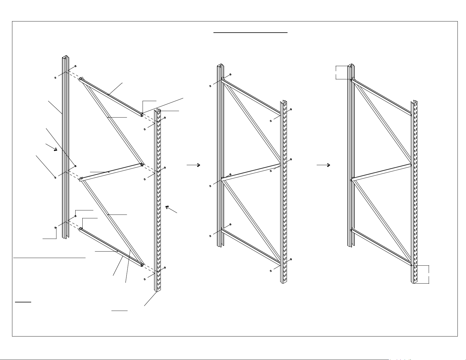
STEP 1:
1 - LAYDOWN 2 UPRIGHTS ON THE FLOOR, WITH OPEN SIDES FACING EACH OTHER.
2 - WHEN ASSEMBLING BOTTOM & TOP HORIZONTOL BRACING, USE THE RUBBER SPACER
3 - CONNECT ONE END OF THE HORIZONTOL BRACING WITH 1ST UPRIGHT AND CONNECT
THE OTHER END OF HORIZONTOL BRACING AND ANGLE BRACING WITH THE 2ND UPRIGHT
4 - USE RUBBER BASE UPRIGHT GRIP ON BOTTOM OF THE UPRIGHTS.
Horizontal bracing
GRAVITY FLOW RACK
6 3/4"
1
6
5
angle bracing
nut
rubber spacer
bolt
Horizontol bracing
PARTS LIST TO ASSEMBLE UPRIGHTS:
1 - UPRIGHT - 4 PCS./UNIT
2 - HORIZONTOL BRACING - 4PCS./UNIT
3 - ANGLE BRACING - 6PCS./UNIT
4 - RUBBER SPACERS - 4PCS./UNIT
5 - BOLT: M8X1.25X50MM - 12PCS./UNIT
6 - NUT: M8X1.25 - 12PCS./UNIT
7 - RUBBER BASE UPRIGHT GRIP - 4PCS./UNIT
angle bracking
angle bracing
2
3
rubber spacer
4
upright
7 1/4"
FLOW-3
UPRIGHT - 84"
HORIZONTAL BRACE OVERALL LENGTH - 34"
ANGLE BRACE OVERALL LENGTH - 41.60"
DIVIDER OVERALL LENGTH - 37"
ROLLER OVERALL LENGTH - 37"
FLOW-4
UPRIGHT HEIGHT - 84"
HORIZONTOL BRACE OVERALL LENGTH - 46"
ANGLE OVERALL LENGTH - 52"
DIVIDER OVERALL LENGTH - 49"
ROLLER OVERALL LENGTH - 49"
7
Page 2
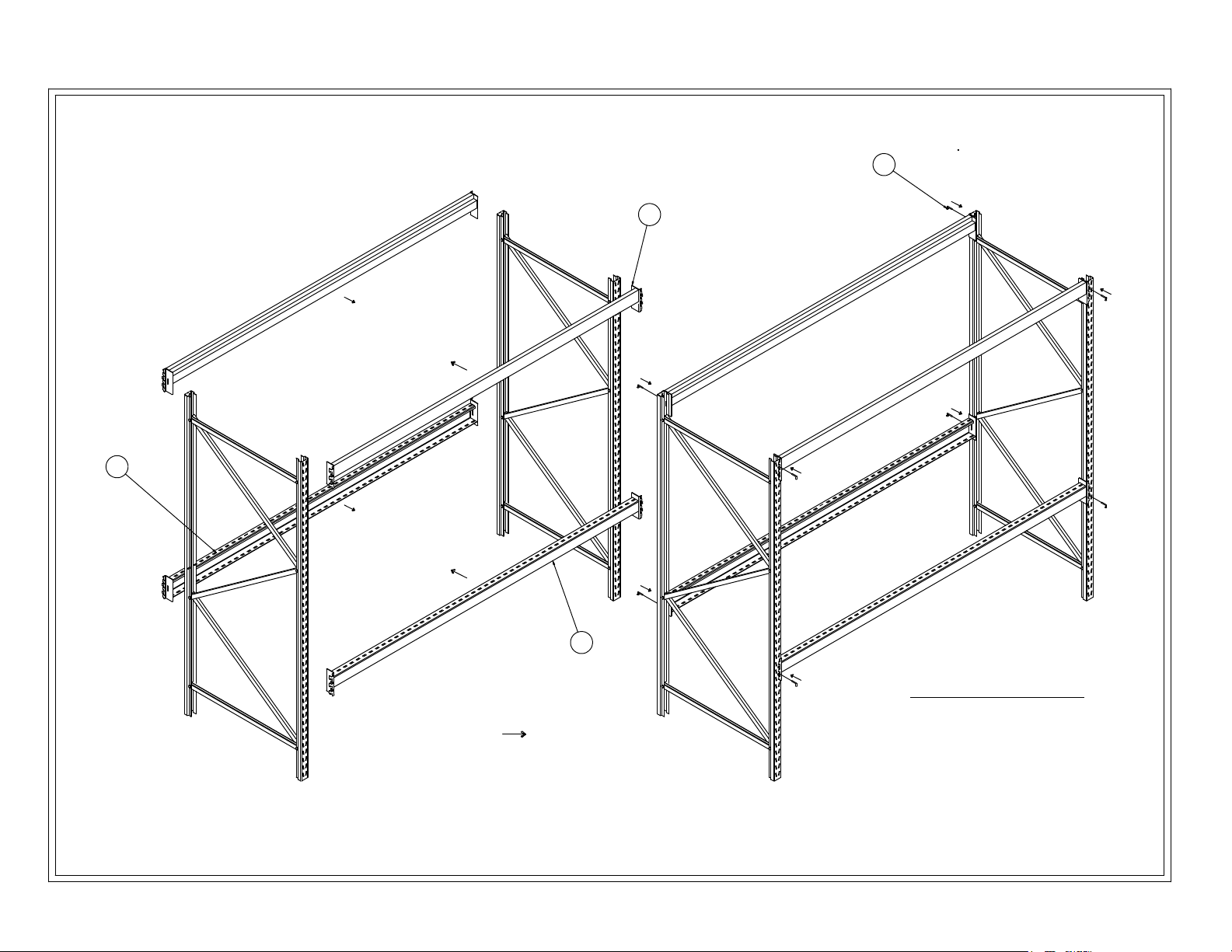
STEP 2:
1 - Assemble 2 top beams (beam tabs should fit in upright slots).
2 - Assemble roller beams at desired height (beam tabs should fit in upright slots).
3 - Install safety pin in all beams ( two per beam)
3
4
1
2
PARTS LIST TO ASSEMBLE THE BEAMS.
1 - TOP BEAM - 2PCS./UNIT
2 - REAR ROLLER BEAM - 3PCS/UNIT FOR FLOW-3
- 4PCS/UNIT FOR FLOW-4
- 5PCS/UNIT FOR FLOW-5
3 - FRONT ROLLER BEAM - 3PCS/UNIT FOR FLOW-3
- 4PCS/UNIT FOR FLOW-4
- 5PCS/UNIT FOR FLOW-5
4 - SAFETY PIN - 2PCS/BEAM
16 PCS. FOR FLOW-3
20 PCS. FOR FLOW-4
24 PCS. FOR FLOW-5
Page 3
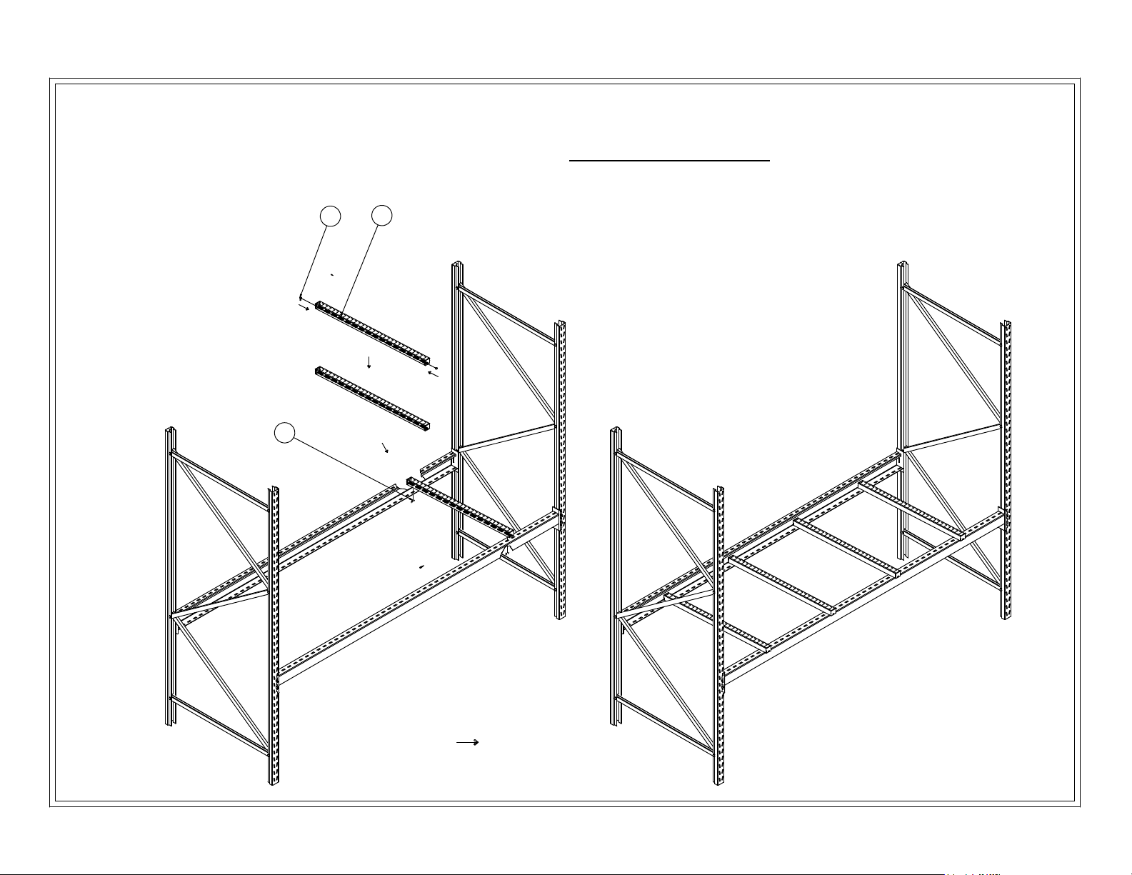
STEP 3:
1 - Assemble 8 rollers per shlef.
2 - Assemble 4 dividers per shelf.
PARTS LIST TO ASSEMBLE ROLLERS & DIV IDERS
1 - 8 ROLLERS PER SHELF
FLOW-3-3: 24 ROLLERS
FLOW-3-4: 32 ROLLERS
3
5
1
FLOW-3-5: 40 ROLLERS
2 - 4 DIVIDERS PER SHELF (not shown in the drawing)
FLOW-3-3: 12 DIVIDERS
FLOW-3-4: 16 DIVIDERS
FLOW-3-5: 20 DIVIDERS
3 - M6X1.00X25mm BOLT - 16PCS/SHELF
FLOW-3-3: Total bolt 48 PCS.
FLOW-3-4: Total bolts 64 PCS.
FLOW-3-5: Total bolts 80 PCS.
4 - M6x1.00x10.00mm Shoulder bolt - 8PCS/DIVIDER (not shown in the
drawing)
FLOW-3-3: Total bolts 24 PCS.
FLOW-3-4: Total bolts 32 PCS.
FLOW-3-5: Total bolts 40 PCS.
5 - M6x1.00 WING NUT
FLOW-3-3: Total wing nuts 72 PCS.
FLOW-3-4: Total wing nuts 96 PCS.
FLOW-3-5: Total wing nuts
120
PCS.
ÃÏ
Page 4

STEP 4
BOLT TWO UNITS TOGETHER TO MAKE A CONTINUOUS GRAVITY FLOW RACK
PARTS LIST TO ASSEMBLE 2 RACKS TOGETHER
1 - THREADED STUD M8X1.25X70MM - 6PCS/UNIT
2 - NUT M8X1.25 - 18PCS/UNIT
2
NUT
THREADED STUD
1
(IF APPLICABLE)
8"
NUT
42"
8"
Page 5

GRAVITY FLOW RACK ASSEMBLY INSTRUCTIONS
9/24/2007
Fig.1
M8-1.25x50mm long Bolt (12 pcs/unit)
to secure horizontal & angle bracing to
to uprights
Position of bottom horizontal brace (Fig.2)
7 1/4"
Fig.2
Page 6

Position of top horizontal brace (Fig.3)
6 3/4"
Fig.3
Spacer 4 pcs/unit
Fig.4
Page 7

Roller bar
Fig.5
M6-1.25x25mm long Bolt 16 pcs/shelf to secure 8 roller
bars.
M6-1.25 Wing Nut 16 pcs/shelf to secure 8 Roller bars
M6-1.25 Wing Nut 8pcs/shelf to secure 4 dividers
M6-1.25x10mm long Shoulder Bolt 8 pcs/shelf to secure 4 dividers
Divider
Fig.6
Page 8

Bolt two units together to make a continuous Gravity Flow Rack
Fig.9
M8-1.25 nut as a spacer between 2 racks, 18pcs./unit
M8-1.25x70mm long stud, 6 pcs./unit
Fig.10
 Loading...