

Page 1
Rev. 0213 EPT, Manual.doc
VESTIL MANUFACTURING CORP.
2999 North Wayne Street, P.O. Box 507, Angola, IN 46703
Telephone: (260) 665-7586 -or- Toll Free (800) 348-0868
Fax: (260) 665-1339
www.vestilmfg.com e-mail: sales@vestil.com
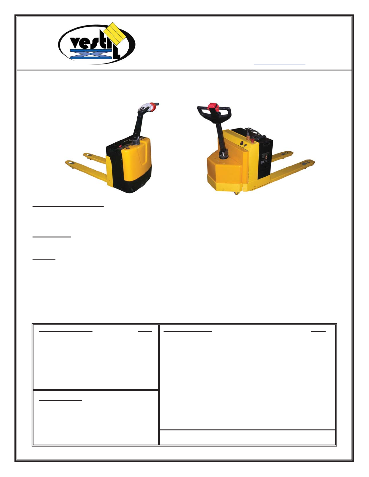
EPT-SERIES ELECTRIC PALLET TRUCKS
OPERATION AND MAINTENANCE MANUAL
Receiving instructions:
After delivery, IMMEDIATELY remove the packaging from the product in a manner that preserves the
packaging and maintains the orientation of the product in the packaging; then inspect the product closely to
determine whether it sustained damage during transport. If damage is discovered during the inspection,
immediately
record a complete description of the damage on the bill of lading. If the product is
undamaged, discard the packaging.
NOTES
:
1) Compliance with laws, regulations, codes, and non-voluntary standards enforced in the location where
the product is used is exclusively the responsibility of the owner/end-user.
2) VESTIL is not liable for any injury or property damage that occurs as a consequence of failing to apply either:
a) Instructions in this manual; or b) Information provided on labels affixed to the product.
Neither is Vestil
responsible for any consequential damages sustained as a result of failing to exercise sound judgment
while assembling, installing, using or maintaining this product.
TABLE OF CONTENTS PAGE TABLE OF FIGURES PAGE
Safety Principles 2 Fig. 1A EPT Main Body Components 5
Product Introduction 2 Fig. 1B EPT-30 (optional) Scale Components 6
Safety Guidelines 3 Fig. 2 EPT-30 Hydraulic Cylinder Assembly 7
Removing EPT from Pallet 3 - 4 Fig. 3 EPT-30 Drive Wheel Assembly 8
st
Use, 1
Operation 20-21 Fig. 4B EPT-30 Fork & Carriage (optional) Scale 10
Lifting & Transporting Loads 21 Fig. 5A Control Yoke & Handle Components 11-12
Batteries & Charger 21-22 Fig. 5B Control Yoke & Handle (optional) Scale 13-14
Fig. 6 Hydraulic Pump & Motor Assemblies 15
Troubleshooting
Changing Motor Assy. 37-39 Fig. 10 EPT-45 Fork & Carriage Assemblies 18
Changing Battery Charger 43-46 Maintenance & Inspections 49-50
Adding Quencharcs 47-48 Markings 51
Inspection, & Functions Tests 20 Fig. 4A EPT-30 Fork & Carriage 9
23-48 Fig. 7 EPT-45 Main Housings & Supporting Structure 16
Changing Cylinder 28-31 Fig. 8 Removable Battery Box & Components 16
Changing Throttle Assy. 32-36 Fig. 9 EPT-45 Cylinder & Fuse Panel 17
Replacing Forward/Reverse Contactor 40-42 Fig. 11 Function Controls, Gauges, & Safety Features 19
Copyright 2013 Vestil Manufacturing Corp. Page 1 of 51
Page 2

Rev. 0213 EPT, Manual.doc
PRODUCT INTRODUCTION
Specifications for each of the 4 models appear in the table below:
Net Wt. Fork Size Service
MODEL (lbs.)
EPT-2047-30 660 20in. X 47in. 3.2 to 7.8 3,000 28 x 65 x 49
EPT-2547-30 671 25in. x 47in. 3.2 to 7.8 3,000 28 x 65 x 49
EPT-2048-45 990 20in. x 48in. 3.4 to 8 4,500 30x 78.5 x 49
EPT-2748-45 1012 27in. x 48in. 3.4 to 8 4,500 30x 78.5 x 49
Vestil Manufacturing Corp. created this manual to acquaint owners and users of our electric pallet trucks
with safe operation and maintenance procedures. Employers are responsible for instructing employees to
use the product properly. Employees and any other persons, who might foreseeably use, repair, or
perform maintenance on the EPT must read and understand every instruction BEFORE using the device.
Cart operators should have access to the manual at all times and should review the directions before each
use. Contact Vestil for answers to any question you have after reading the entire manu al.
Although Vestil diligently strives to identify foreseeable hazardous situations, this manual cannot address
every conceivable danger. The end-user is ultimately responsible for exercising sound judgment at all times.
Thank you for purchasing an electric pallet truck (“EPT,” “pallet truck,” “truck,” or
“unit”) offered by Vestil Manufacturing Corporation (“Vestil”). Our EPT’s are durable,
high-quality products that combine safety features and low-maintenance mechanisms.
Despite the product’s relatively simple mechanics, all personnel must familiarize
themselves with the safe operation instructions provided in this manual.
(W x L) in inches Range (in.)
Capacity
(lbs.)
Overall Size
(W X L x H) in inches
SAFETY PRINCIPLES
We offer four types of electric pallet truck (EPT): two 3,000 pound (~1364kg) capacity models, the EPT-204730 and 2547-30, and two 4,500 pound (~2045kg) capacity models, the EPT-2048-45 and 2748-45. Each unit
conforms to the generalized specifications disclosed in this manual and fulfills our demanding standards for
quality, safety and durability.
Vestil Manufacturing Corp. recognizes the critical importance of workplace safety. Each person who might
participate in operation or maintenance of the product must read this manual. Read the entire manual and fully
understand the directions BEFORE using or performing maintenance on the cart. If you do not
understand an instruction, contact Vestil for clarification. Failure to adhere to the directions in this
manual might lead to serious personal injury or even death.
Vestil is not liable for any injury or property damage that occurs as a consequence of failing to apply the safe
operation and maintenance procedures explained in this manual or that appear on labels affixed to the product.
Furthermore, failure to exercise good judgment and common sense may result in property damage, serious
personal injury, or death, and also are not the responsibility of Vestil.
This manual applies the hazard identification methods suggested for instruction manuals by the American
National Standards Institute (ANSI). In accordance with ANSI guidelines for hazard identification language, this
manual classifies personal injury risks and situations that could lead to property damage with SIGNAL WORDS.
These signal words announce an associated safety message. The reader must understand that the signal word
chosen indicates the seriousness of that hazard according to the following convention:
Identifies a hazardous situation which, if not avoided, WILL result in DEATH or SERIOUS
INJURY. Use of this signal word is limited to the most extreme situations.
Identifies a hazardous situation which, if not avoided, COULD result in DEATH or
SERIOUS INJURY.
Indicates a hazardous situation which, if not avoided, COULD result in MINOR or
MODERATE injury.
Identifies practices not related to personal injury, such as operation that could damage the cart.
No safety alert symbol (equilateral triangle enclosing an exclamation point) accompanies th is
signal word.
Copyright 2013 Vestil Manufacturing Corp. Page 2 of 51
Page 3
Rev. 0213 EPT, Manual.doc
SAFETY GUIDELINES
Failure to read and understand the instructions included in this manual before using or servicing the
pallet truck constitutes misuse of the product. Study the entire manual before you use the truck for the
first time and before each subsequent use. Read the manual to refresh your understanding of the safe use and
maintenance procedures on p. 50-51. If questions remain after you finish reading the manual, contact Vestil for
answers. DO NOT attempt to resolve any problem with the truck unless you are certain
afterwards.
that it will be safe to use
To decrease the risk of electrocution:
¾ DO NOT contact or operate the pallet truck close to electrified wires or other sources of electricity;
¾ Before operating the EPT, always inspect the area where you will use it.
Improper use might result in serious personal injuries to the operator and/or bystanders. To
minimize the possibility of injury, ALL persons who might operate, perform maintenance on, or service the EPT
must read, understand and apply the following instructions:
x DO NOT operate the EPT unless and until you are:
1. Trained to use the machine; AND
2. Certified as a trained operator by your employer in accordance with U.S. OSHA regulations (29 CFR
§1910.178) and any standards incorporated by reference (e.g. ANSI/ITSDF B56.1-2005).
x DO NOT attempt to lift or transport loads that exceed the rated capacity.
x Inspect the machine before each use; DO NOT use the EPT unless it is in normal condition. Normal
operating condition exists if the EPT passes the inspection and functions tests described under the heading,
“Inspect the EPT & Perform a Functions Tests” on p. 20.
x DO NOT use the unit until you read and understand the entire owner’s manual. Review the manual before
each use AND before performing maintenance on the device.
x DO NOT use the EPT if the load-supporting elements sustain any structural damage. Structural elements
include, but are not limited to, the forks, carriage, and wheels. If structural damage is present, immediately
tag the unit “Out of Service” and inform maintenance personnel of the problem.
x DO NOT use the EPT if it makes unusual noises during operation.
x DO NOT allow people to ride on the pallet truck. Only the operator of an EPT equipped with a properly
installed rider platform (EPT
x DO NOT attempt to lift an unevenly distributed load. Always center and evenly distribute the load on the forks.
x DO NOT operate the EPT on surfaces (ramps or grades) angled more than 4 degrees.
x DO NOT leave the EPT unattended while it supports a load. Always fully lower the forks, and then completely
disengage the skid or pallet. Complete the parking / storing procedure described in “Storing the EPT” on p.
22.
x DO NOT modify the pallet truck without first receiving written authorization from Vestil. Unauthorized
modifications may make the EPT unsafe to use.
To maximize the service life of the EPT and to prevent damage:
x Always store the machine in a secure, dry location where it will not interfere with traffic or other activities.
x Maintain the product as suggested in “Maintenance & Inspections” on p. 49-50.
REMOVING THE PALLET TRUCK FROM THE SHIPPING PALLET:
The pallet truck is shipped in ready-to-use condition. However, it must first be removed from the shipping pallet
before it can be used for the first time.
DO NOT attempt to drive the pallet truck off of the pallet; it might tip over and cause bodily injuries
or property damage. To minimize the risk of injury to yourself or other persons, perform the following steps to
remove the machine from the shipping pallet:
1. Remove all packing material.
2. Inform all personnel not participating in the unpacking process to clear the area.
3. Lift the EPT off of the pallet using either a hoist or a forklift with a capacity of at least 2,000 pounds. Always
apply the proper hoisting procedures or forklift operation practices you learned during your trai ning program.
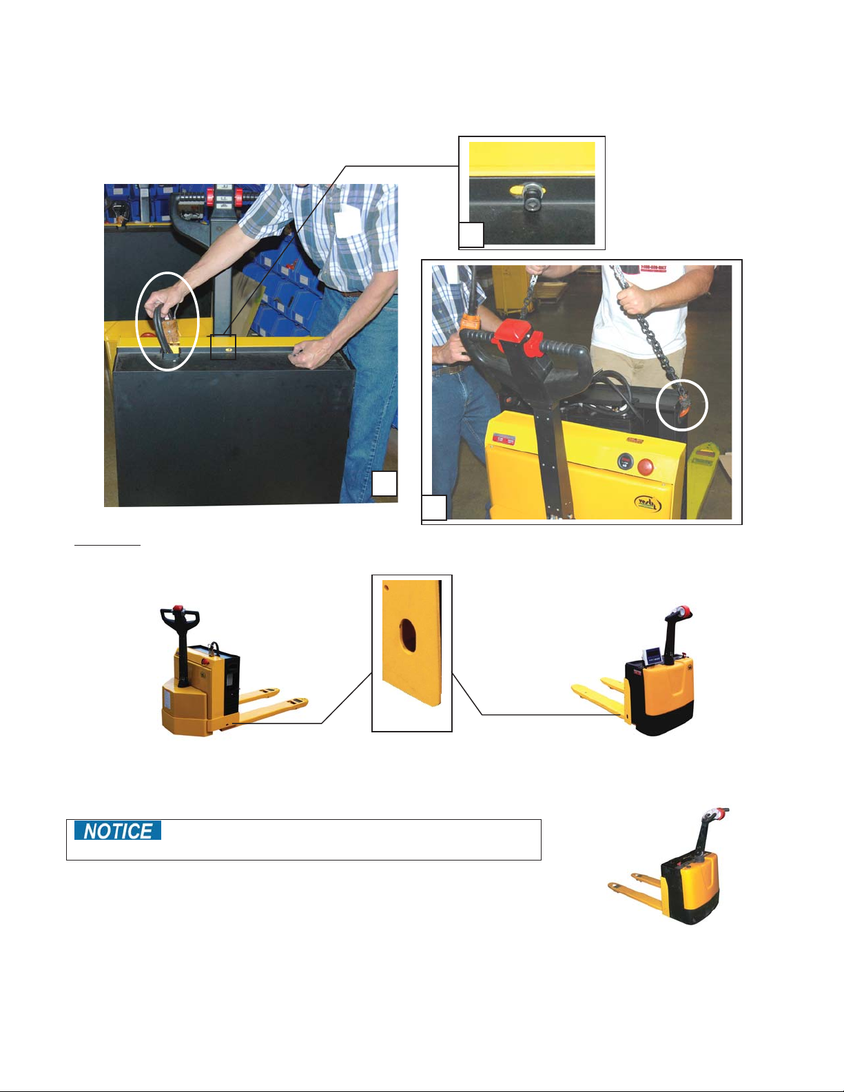
To remove the EPT from the shipping pallet using a hoist:
EPT-2###-45 models: Remove the battery box.
a) Disconnect the power cable from the socket on top of the EPT housing (circled in photo 1 below). Unfasten the
box from the EPT frame by unscrewing the bolt in the center of the flange; the bolt is shown in photograph 2 (next
page).
Copyright 2013 Vestil Manufacturing Corp. Page 3 of 51
Page 4
Rev. 0213 EPT, Manual.doc
b) Connect the sling to both hook points on the EPT (1 on each side; the picture below only shows the hook point
on the right side); then lift the unit no more than 6 – 8 inches above the pallet. The EPT will tilt towards the
control yoke. Additionally, it may swing from side-to-side once free of the pallet if you did not properly position the
hoist above the center of the sling. Stabilize the suspended truck with one hand, and stand safely to the side while
operating the hoist.
1
2
3
All Models: Securely connect the sling hooks to the hook points (see photographs below), lift the EPT a few
inches off of the pallet, direct the EPT away from the pallet, and then lower it until it is entirely supported by the
ground.
EPT-45 EPT-30
Hook point
To lift the EPT with a forklift:
Avoid contacting the drive wheel with the tines of your
forklift; contact could damage the drive wheel.
Loading
side
Approach the pallet truck from the operator side. Lift the EPT just a few
inches above the pallet. Slowly back the forklift away from the pallet, and
then carefully lower the forks until the EPT rests firmly on the ground.
Operator
Side
Copyright 2013 Vestil Manufacturing Corp. Page 4 of 51
Page 5
Rev. 0213 EPT, Manual.doc
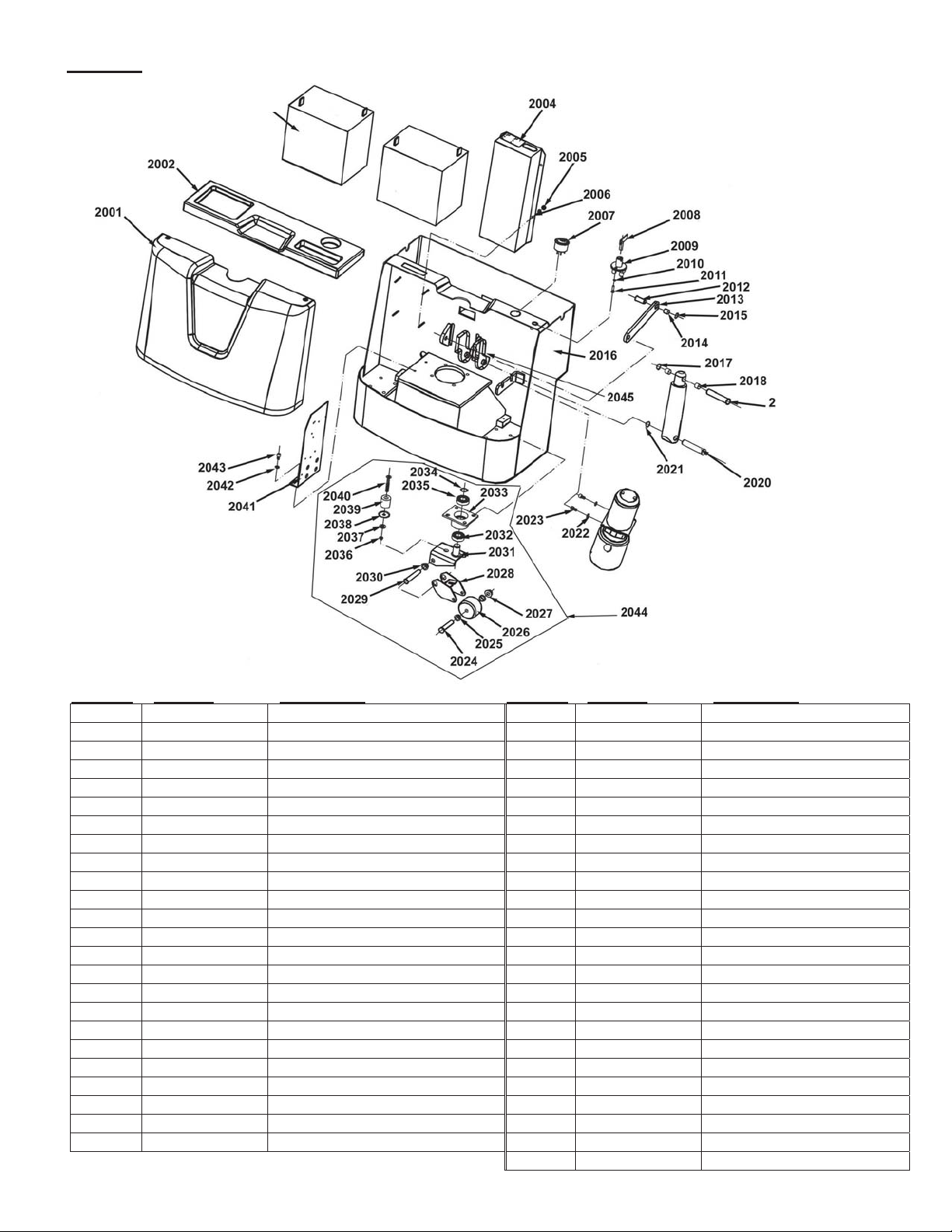
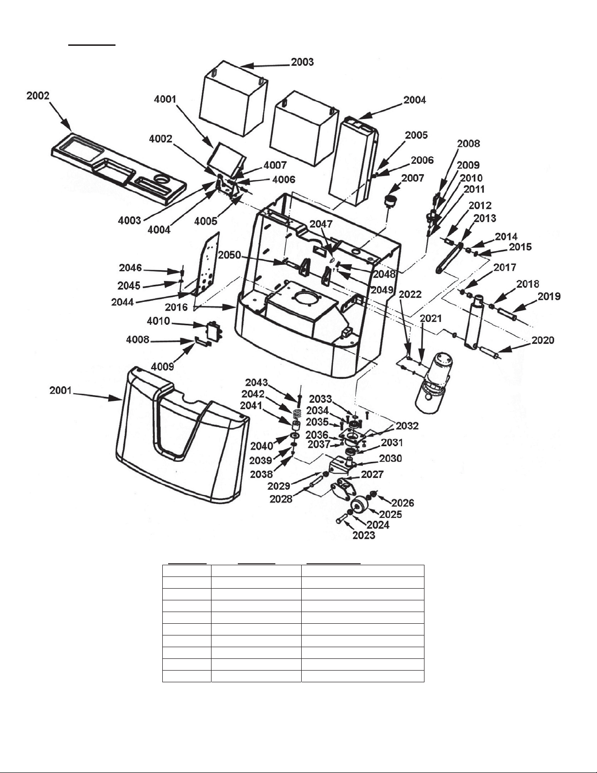
FIG. 1A: EPT-30 MODELS MAIN BODY COMPONENTS
2003
Item No. Part No. Description Item No. Part No. Description
2001 EPT-30-2001 Main Body Housing 2021 EPT-30-2021 22mm Snap Ring
EPT-30-2001-2
2002 EPT-30-2002 Battery Cover 2023 EPT-30-2023 M10 x 22 Screw
2003 EPT-30-2003 Battery (2 per unit) 2024 EPT-30-2024 Bolt
2004 EPT-30-2004 Battery Charger (OEM) 2025 EPT-30-2025 Bolt
EPT-30-2004-2 Replacement Charger (OEM Unit)
EPT-CORD Battery Charger Cord 2027 EPT-30-2027 M12 Nut
2005 EPT-30-2005 M6 Spring Washer 2028 EPT-30-2028 Wheel Frame
2006 EPT-30-2006 M6 Nut 2029 EPT-30-2029 Shaft
2007 EPT-30-2007 24V Battery Charge Gauge 2030 EPT-30-2030 Bushing
2008 EPT-30-2008 Key Switch 2031 EPT-30-2031 Bearing Plate
2009 EPT-30-2009 Emergency Stop Switch 2032 EPT-30-2032 Bearing 30205
EPT-30-KSA Key Switch Assembly 2033 EPT-30-2033 Bearing Plate
2010 EPT-30-2010 M6 Flat Washer 2034 EPT-30-2034 Ball Bearing 6205
2011 EPT-30-2011 M6 x 25 Bolt 2035 EPT-30-2035 25mm Washer
2012 EPT-30-2012 Set Pin 2036 EPT-30-2036 M10 Nut
2013 EPT-30-2013 Pivot Link Arm 2037 EPT-30-2037 8mm Washer
2014 EPT-30-2014 Bushing 2038 EPT-30-2038 Fixed Ring
2015 EPT-30-2015 16mm Snap Ring 2039 EPT-30-2039 Link Rod
2016 EPT-30-2016 Main Body 2040 EPT-30-2040 Bolt
2017 EPT-30-2017 20mm Snap Ring 2041 EPT-30-2041 Mounting Plate
2018 EPT-30-2018 Bushing 2042 EPT-30-2042 8mm Washer
2019 EPT-30-2019 Cylinder Pivot Pin, Upper 2043 EPT-30-2043 Bolt
2020 EPT-30-2020 Cylinder Pivot Pin, Lower 2044 EPT-30-2044 Wheel Stabilizer Assembly
2045 EPT-30-2045 Upper Travel Limit Switch
Housing Screw 2022 EPT-30-2022 10mm Washer
2026 EPT-30-2026 Wheel 76 x 36
Copyright 2013 Vestil Manufacturing Corp. Page 5 of 51
Page 6
Rev. 0213 EPT, Manual.doc
FIG. 1B: EPT-30 MODELS (OPTIONAL) SCALE COMPONENTS
Item No. Part No. Description
4001 EPT-30-SCL-4001 Scale Display
4002 EPT-30-SCL-4002 Display Mounting Bracket
4003 EPT-30-SCL-4003 6mm Flat Washer
4004 EPT-30-SCL-4004 M6 x 10 Bolt
4005 EPT-30-SCL-4005 M6 x 30 Bolt
4006 EPT-30-SCL-4006 6mm Spring Washer
4007 EPT-30-SCL-4007 M6 Nut
4008 EPT-30-SCL-4008 M6 Nut
4009 EPT-30-SCL-4009
4010 EPT-30-SCL-4010
Copyright 2013 Vestil Manufacturing Corp. Page 6 of 51
Page 7
Rev. 0213 EPT, Manual.doc
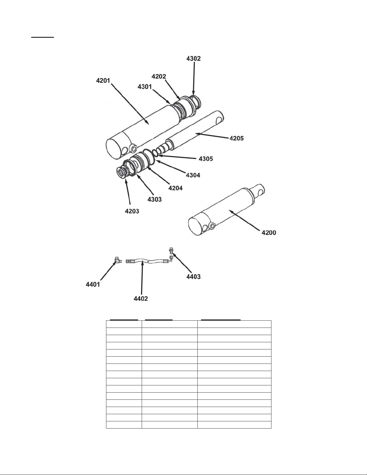
FIG. 2: EPT-30 MODELS HYDRAULIC CYLINDER ASSEMBLY
Item No. Part No. Description
4200 EPT-30-4200 Cylinder Assembly
4201 EPT-30-4201 Cylinder Body Tube
4202 EPT-30-4202 Gland Tube
4203 EPT-30-4203 Nut
4204 EPT-30-4204 Piston
4205 EPT-30-4205 Piston Rod
4301 EPT-30-4301 O-Ring
4302 EPT-30-4302 Seal Ring
4303 EPT-30-4303 Seal Ring
4304 EPT-30-4304 O-Ring
4305 EPT-30-4305 O-Ring
4401 EPT-30-4401
4402 EPT-30-4402 Hydraulic Hose
4403 EPT-30-4403
4300 EPT-30-4300 Seal Kit (EPT 30 & 45)
Copyright 2013 Vestil Manufacturing Corp. Page 7 of 51
Page 8
Rev. 0213 EPT, Manual.doc
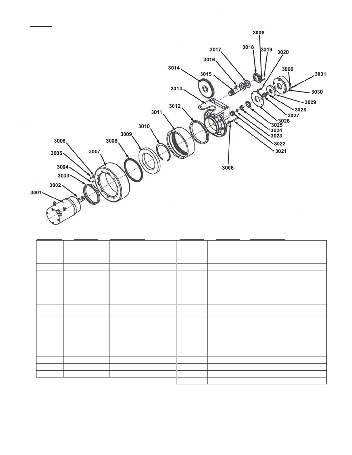
FIG. 3: EPT-30 MODELS DRIVE WHEEL ASSEMBLY
Item No. Part No. Description Item No. Part No. Description
Not
Shown
EPT-30/45-DBA
3300 EPT-30-DWA
3001 EPT-30-3001
3002 EPT-30-3002
3003 EPT-30-3003
3004 EPT-30-3004
3005 EPT-30-3005
3006 EPT-30-3006
3007 EPT-30-3007
3007 EPT-30-3007-R
3008 EPT-30-3008
3009 EPT-30-3009
3010 EPT-30-3010
301 EPT-30-3011
3012 EPT-30-3012
3013 EPT-30-3013
3014 EPT-30-3014
Drive Brake Assembly
Complete Drive Wheel
Assembly (includes Motor)
24VDC (700W) Drive Motor
Woodruf Key
Motor Adaptor Ring
5 x 16 Dowel Pin
M6 x 15 Cap Screw
6mm Washer
Replacement Polyurethane
Drive Wheel
Replacement Rubber Drive
Wheel
140 x 180 x 12 Oil Seal
Wheel Bearing
Snap Ring
Bull Gear
Grease Seal
Gear Box Casting
Idler Gear
3015 EPT-30-3015 Pinion Gear
3016 EPT-30-3016 Key
3017 EPT-30-3017 Pinion Gear Bearing
3018 EPT-30-3018 Cap
3019 EPT-30-3019 Cap Screw
3020 EPT-30-3020 M6 x 15 Cap Screw
3021 EPT-30-3021 Motor Retainer Cap Screw
3022 EPT-30-3022 Drive Gear
3023 EPT-30-3023 Spacer
3024 EPT-30-3024 Motor Shaft Pilot Bearing
3025 EPT-30-3025 Spacer
3026 EPT-30-3026 Brake Mounting Adapter
3027 EPT-30-3027 Splined Coupling
3028 EPT-30-3028 Snap Ring
3029 EPT-30-3029 Brake Pad
3030 EPT-30-3030 Brake Coil
3031 EPT-30-3031 Cap Screw
EPT-30-MTR-BLT
M6-1.0 x 185mm Motor Bolt
Copyright 2013 Vestil Manufacturing Corp. Page 8 of 51
Page 9
Rev. 0213 EPT, Manual.doc
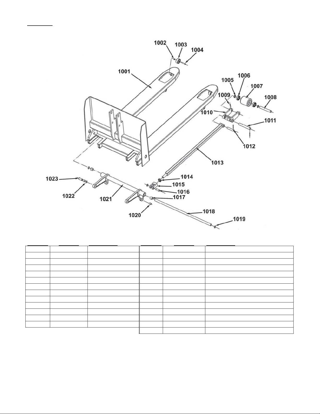
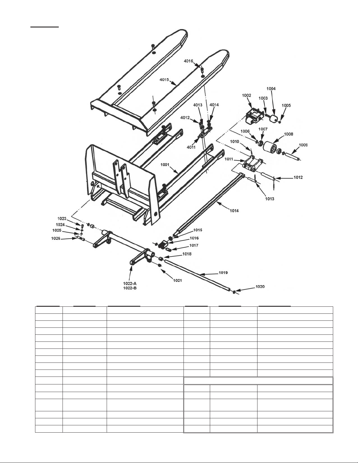
FIG. 4A: EPT-30 MODELS FORK AND CARRIAGE
Item No. Part No. Description Item No. Part No. Description
1001 EPT-30-1001 Fork Assembly 1012 EPT-30-1012-2 Push Rod Pin (Hole in Center)
1002 EPT-30-1002 M6 Nut 1013 EPT-30-1013 40” Push Rod
1003 EPT-30-1003 Nose Wheel 1013-2 EPT-30-1013-2 37-1/2” Push Rod
1004 EPT-30-1004 M6 x 45 Screw 1014 EPT-30-1014 Lock Nut
1005 EPT-30-1005 Snap Ring 1015 EPT-30-1015 Clevis
1006 EPT-30-1006 Ball Bearing 6204z 1016 EPT-30-1016 Clevis Pin
1007 EPT-30-1007 75 x 96 Load Roller 1017 EPT-30-1017 22 x 20 Sleeve Bearing
1008 EPT-30-1008 Load Roller Axle 1018 EPT-30-1018 Trunion Shaft
1009 EPT-30-1009 5 x 30 Roll Pin 1019 EPT-30-1019 16mm Snap Ring
1010 EPT-30-1010 Load Roller Bracket 1020 EPT-30-1020 16 x 16 Clevis Pin Sleeve Bearing
1011 EPT-30-1011 Bracket Pin 1021 EPT-30-1021-25 Trunion (Mod el EPT-2547-30)
Not Shown
1012 EPT-30-1012 Push Rod Pin 1022 EPT-30-1022 22mm Snap Ring
EPT-30-EXT-RL
1023 EPT-30-1023 Pin
Steel Exit Roller 1021 EPT-30-1021-20 Trunion (Model EPT-204 7-30)
Copyright 2013 Vestil Manufacturing Corp. Page 9 of 51
Page 10
Rev. 0213 EPT, Manual.doc
FIG. 4B: EPT-30 MODELS FORKS AND CARRIAGE WITH INTEGRATED SCALE
Item No. Part No. Description Item No. Part No. Description
1001
1002
1003
1004
1005
1006
1007
1008
1009
1010
1011
1012
1013
1014
1015
1016
1017
EPT-30-SCL-1001
EPT-30-SCL-1002
EPT-30-SCL-1003
EPT-30-SCL-1004
EPT-30-SCL-1005
EPT-30-SCL-1006
EPT-30-SCL-1007
EPT-30-SCL-1008
EPT-30-SCL-1009
EPT-30-SCL-1010
EPT-30-SCL-1011
EPT-30-SCL-1012
EPT-30-SCL-1013
EPT-30-SCL-1014
EPT-30-SCL-1015
EPT-30-SCL-1016
EPT-30-SCL-1017
Fork Assembly 1018
Nose Wheel Frame 1019
M10 x 65 Screw 1020
Nose Wheel 1021
M10 Nut 1022-A
Retaining Ring 1022-B
Ball Bearing 6204z 1023
Drive/Load Wheel 75 x 90 1024
Drive/Load Wheel Axle 1025
Roll Pin 5 x 30 1026
Load Roller Bracket
Load Roller Bracket Pivot Pin
Push Rod Pivot Pin 4012
Push Rod (Owner must provide
measurement)
M22 x 1.5 Lock Nut 4014
Push Rod Clevis 4015
Clevis Pin 4016
4011
4013
EPT-30-SCL-1018
EPT-30-SCL-1019
EPT-30-SCL-1020
EPT-30-SCL-1021 Clevis Pin Sleeve Bearing 16 x 16
EPT-30-SCL-1022-A
EPT-30-SCL-1022-B
EPT-30-SCL-1023
EPT-30-SCL-1024
EPT-30-SCL-1025
EPT-30-SCL-1026
Integral Scale Components
EPT-30-SCL-4011
EPT-30-SCL-4012
EPT-30-SCL-4013
EPT-30-SCL-4014
EPT-30-SCL-4015
EPT-30-SCL-4016
Sleeve Bearing 22 x 20
Trunion Pivot Shaft
Retaining Ring 16
Trunion (EPT-2547-30-SCL)
Trunion (EPT-2047-30-SCL)
M8 x 30 Screw
Washer
M8 Nut
Pin
Load Cell
M12 x 45 Bolt
12mm Spring Washer
Washer
Weighing Forks
M12 x 38 Bolt
Copyright 2013 Vestil Manufacturing Corp. Page 10 of 51
Page 11
Rev. 0213 EPT, Manual.doc
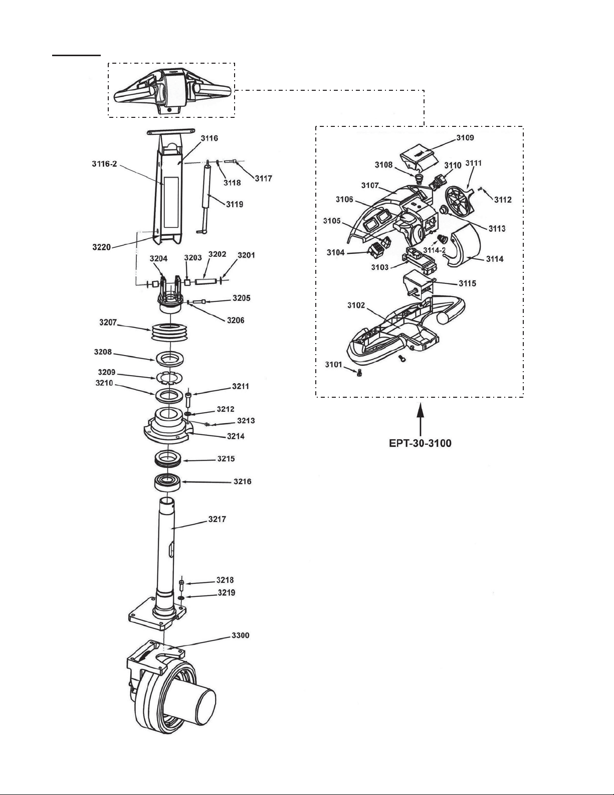
FIG. 5A: CONTROL YOKE AND HANDLE COMPONENTS (ALL MODELS)
Copyright 2013 Vestil Manufacturing Corp. Page 11 of 51
Page 12

Rev. 0213 EPT, Manual.doc
Item No. Part Number Description
3100 EPT-30-3100-2 Control Handle
3101 EPT-30-3101 Screw
3102 EPT-30-3102 Handle Cover (Bottom)
3103 EPT-30-3103 Throttle Seat with Switches
3103-2 EPT-30-3103-2 Belly / Horn Switch
3104 EPT-30-3104 Electrical Outlet (Big)
3105 EPT-30-3105 Electrical Outlet (Small)
3106 EPT-30-3106 Throttle Knob (Left)
3107 EPT-30-310 7 Top Handle Cover (grey)
3108 EPT-30-3108 Spring – (Same as EPT-30-3114-2)
3109 EPT-30-3109 Horn Switch Operator
3110 EPT-30-3110
3111 EPT-30-3111 Throttle Knob (right)
3112 EPT-30-3112 M3 x 10 Screw
3113 EPT-30-3113 Throttle Shaft Bushing
3114 EPT-30-3114 Emergency Reverse Switch Cover
3114-2 EPT-30-3114-2 Emergency Reverse Return Spring
3115 EPT-30-3115 Throttle Assembly (identical to EPT-45-1112)
3115 EPT-30-3115-2 Throttle Assembly Unit
3115 EPT-30-3115-3 Curtis Throttle Assembly
3116 EPT-30-3116 Yoke Arm
3116-2 EPT-30-3116-2 Upper Removable Cover
3117 EPT-30-3117 Bolt
3118 EPT-30-3118 8mm Washer
3119 EPT-30-3119 Gas Shock
3201 EPT-30-3201 Snap Ring 20mm
3202 EPT-30-3202 Pivot Pin
3203 EPT-30-3203 Bushing
3204 EPT-30-3204 Handle Coupling (identical to EPT-45-1210)
3205 EPT-30-3205 Hex Head Cap Screw
3206 EPT-30-3206 8mm Washer
3207 EPT-30-3207
3208 EPT-30-3208 M56 x 1.5 Nut
3209 EPT-30-3209 56mm Washer
3210 EPT-30-3210 Washer
3211 EPT-30-3211 Bolt
3212 EPT-30-3212 Washer
3213 EPT-30-3213 Grease Zerk
3214 EPT-30-3214 Bearing Housing
3215 EPT-30-3215 Bearing 8112
3216 EPT-30-3216 Bearing 80113
3217 EPT-30-3217 Steering Post
3218 EPT-30-3218 M10 x 30 Bolt
3219 EPT-30-3219 10mm Washer
3220 EPT-30-3220 Handle Limit Switch
3300 EPT-30-3300 Drive Wheel System
Raise / Lower Button with Micro-Switch
Rubber Coupling Cover (same as EPT-45-1210)
Copyright 2013 Vestil Manufacturing Corp. Page 12 of 51
Page 13
Rev. 0213 EPT, Manual.doc
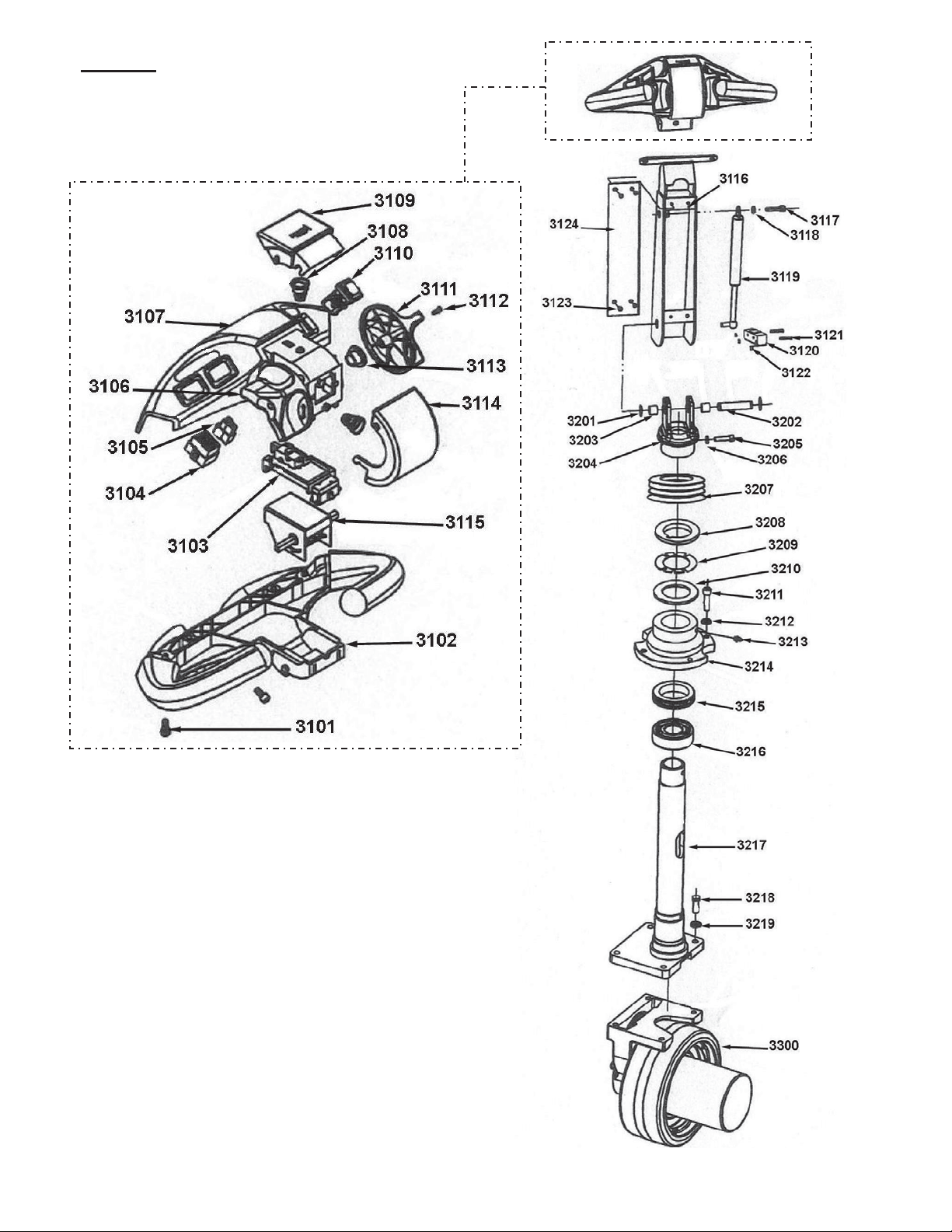
FIG. 5B: CONTROL YOKE AND HANDLE
C
OMPONENTS (ALL MODELS)
WITH
INTEGRAL SCALE
Copyright 2013 Vestil Manufacturing Corp. Page 13 of 51
Page 14

Rev. 0213 EPT, Manual.doc
Item No. Part No. Description
3101 EPT-30-SCL- M6 x 12 Bolt
3102 EPT-30-SCL- Handle Cover (Bottom)
3103 EPT-30-SCL- Throttle Seat
3103-2 EPT-30-SCL- Belly / Horn Switch
3104 EPT-30-SCL- Electrical Outlet (Large)
3105 EPT-30-SCL- Electrical Outlet (Small)
3106 EPT-30-SCL- Throttle Knob (left)
3107 EPT-30-SCL- Handle Cover (Top)
3108 EPT-30-SCL- Spring
3109 EPT-30-SCL- Horn Switch Operator
3110 EPT-30-SCL- Raise / Lower Button
3111 EPT-30-SCL- Throttle Knob
3112 EPT-30-SCL- M3 x 10 Screw
3113 EPT-30-SCL- Throttle Shaft Bushing
3114 EPT-30-SCL-
3114-2 EPT-30-SCL- Switch Cover Spring
3115 EPT-30-SCL- Throttle
3116 EPT-30-SCL- Yoke Arm
3117 EPT-30-SCL- M8 x 10 Bolt
3118 EPT-30-SCL- 8mm Spring Washer
3119 EPT-30-SCL- Gas Shock
3120 EPT-30-SCL- Handle Limit Switch
3121 EPT-30-SCL- M4 x 30 Screw
3122 EPT-30-SCL- M4 Nut
3123 EPT-30-SCL- M5 x 6 Screw
3124 EPT-30-SCL- Yoke Arm Access Panel
3201 EPT-30-SCL- 20mm Washer
3202 EPT-30-SCL- Pivot Pin
3203 EPT-30-SCL- 16 x 20 Sleeve Bearing
3204 EPT-30-SCL- Handle Coupling
3205 EPT-30-SCL- M8 x 30 Bolt
3206 EPT-30-SCL- 8mm Spring Washer
3207 EPT-30-SCL- Rubber Boot, Coupler Cover
3208 EPT-30-SCL- M56 x 1.5 Nut
3209 EPT-30-SCL- Washer 56
3210 EPT-30-SCL- Flat Washer
3211 EPT-30-SCL- M10 x 40 Bolt
3212 EPT-30-SCL- 10mm Spring Washer
3213 EPT-30-SCL- M8 x 1 Grease Zerk
3214 EPT-30-SCL- Bearing Housing
3215 EPT-30-SCL- Bearing 8112
3216 EPT-30-SCL- Ball Bearing 80113
3217 EPT-30-SCL- Steering Post
3218 EPT-30-SCL- M10 x 30 Bolt
3219 EPT-30-SCL- 10mm Flat Washer
3300 EPT-30-SCL- Drive Wheel Assembly
Emergency Stop / Reverse Switch Cover (Red)
Copyright 2013 Vestil Manufacturing Corp. Page 14 of 51
Page 15
Rev. 0213 EPT, Manual.doc
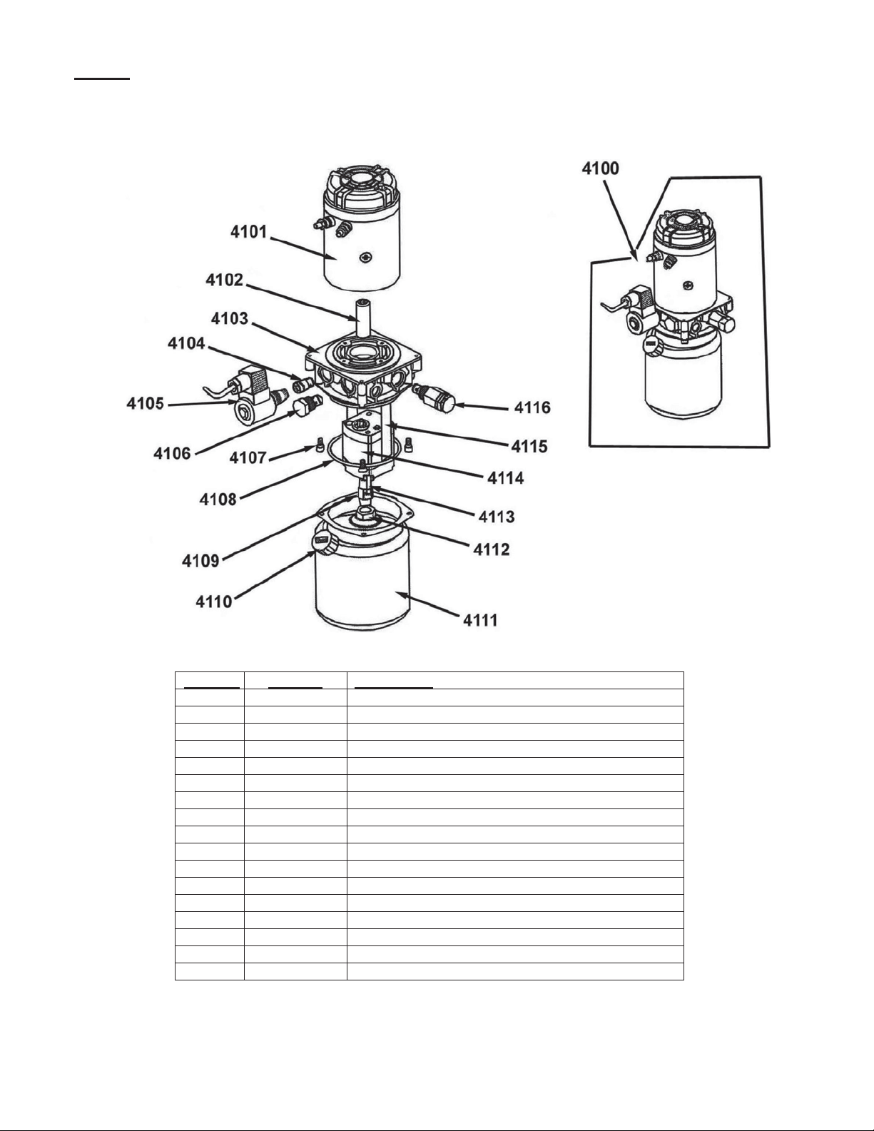
FIG. 6
: Hydraulic Pump and Motor Assemblies (All Models)
Item No. Part No. Description
4100 EPT-30-4100 Complete Motor Pump Assembly
4101 EPT-30-4101 24VDC (1.3kW) DC Motor
4102 EPT-30-4102 Motor-to-Pump Shaft Coupling
4103 EPT-30-4103 Manifold Base
4104 EPT-30-4104 Flow Control Valve 5LMRN
4105 EPT-30-4105 Solenoid Valve
4106 EPT-30-4106 Check Valve
4107 EPT-30-4107 Bolt
4108 EPT-30-4108 90 x 3.1 O-Ring
4109 EPT-30-4109 Pick Up Tube
4110 EPT-30-4110 Breather
4111 EPT-30-4111 Hydraulic Fluid Reservoir
4112 EPT-30-4112 Intake Strainer
4113 EPT-30-4113 Pump Retaining Bolt
4114 EPT-30-4114 Hydraulic Gear Pump
4115 EPT-30-4115 Return Tube
4116 EPT-30-4116 Relief Valve
Copyright 2013 Vestil Manufacturing Corp. Page 15 of 51
Page 16

Rev. 0213 EPT, Manual.doc
7: EPT-45 MAIN HOUSINGS AND SUPPORTING STRUCTURE
FIG.
Item No. Part No. Description
1001
1001
1002
1002
1003
1004
1005
1006
1007
1007
1008
1009
1010
1011
1012
1013
1013
1014
EPT-45-1001 M6 Hood Retaining Screw
EPT-45-1001-1 M5 Hood Retaining Screw
EPT-45-1002 Gear-Drive Cover (Fiberglass)
EPT-45-1002-2 Gear-Drive Cover (Plastic)
EPT-45-1003 Rear Cover Bracket
EPT-45-1004 Bolt
EPT-45-1005 Spring Washer
EPT-45-1006 Washer
EPT-45-1007 Rear Cover (Fiberglass)
EPT045-1007-2 Rear Cover (Plastic)
EPT-45-1008 Rear Frame
EPT-45-1009 Screw
EPT-45-1010 Spring Washer
EPT-45-1011 Snap Ring
EPT-45-1012 Bearing
EPT-45-1013 Wheel
EPT-45-1013-2 Complete Stabilizing Wheel
EPT-45-1014 Wheel Axle
FIG. 8: EPT-45 REMOVABLE BATTERY BOX AND COMPONENTS
Assembly
Copyright 2013 Vestil Manufacturing Corp. Page 16 of 51
Item No. Part No. Description
3002 EPT-45-3002 Battery
3003 EPT-45-3003 Battery Charger – OEM
3003 EPT-45-3003-2 Battery Charger – Soneil
3003 EPT-45-3003-3 Battery Disconnect Connector
EPT-CORD Battery Charger Cord
3004 EPT-45-3004 Battery Box
Page 17

Rev. 0213 EPT, Manual.doc
FIG.
9: EPT-45 CYLINDER AND FUSE PANEL
Item No. Part No. Description Item No. Part No. Description
3005 EPT-45-3005 Spring Washer 3401
3006 EPT-45-3006 Bolt 3402
3007 EPT-45-3007 Retaining Ring 3403
3008 EPT-45-3008 Upper Cylinder Pin 3403
3009 EPT-45-3009 Lower Cylinder Pin 3404
3100 EPT-45-3100 Power Pack 3405
3200 EPT-45-3200 Hydraulic Hose 3406
3300 EPT-45-3300 Hydraulic Cylinder 3406 EPT-45-3406-2
3300 EPT-45-3300-2 Hydraulic Cylinder 3407
3408
EPT-45-3401 150Amp Drive Motor Circuit Fuse
EPT-45-3402 100Amp Pump Circuit Fuse
EPT-45-3403 5Amp Control Circuit Fuse
EPT-45-3403-2 Fuse Holder
EPT-45-3404 Motor Controller
EPT-45-3405 Main Circuit Contactor
EPT-45-3406 Forward/Reverse Contactor
Forward/Reverse Contactor (Curtis)
EPT-45-3407 Pump Motor Contactor
EPT-45-3408 Horn
Copyright 2013 Vestil Manufacturing Corp. Page 17 of 51
Page 18

Rev. 0213 EPT, Manual.doc
FIG. 10: EPT-45 FORK AND CARRIAGE ASSEMBLIES
Item No. Part No. Description Item No. Part No. Description
2001
2002
2003
2004
2004-2
2005
2006
2007
2008
2009
2010
2010-1
2011
2012
2013
2014
EPT-45-2001
EPT-45-2002
EPT-45-2003
EPT-45-2004
EPT-45-2004-2
EPT-45-2005
EPT-45-2006
EPT-45-2007
EPT-45-2008
EPT-45-2009
EPT-45-2010
EPT-45-2010-1
EPT-45-2011
EPT-45-2012
EPT-45-2013
EPT-45-2014
Retaining Ring 2015
Link Arm 2016
Sleeve Bearing 22 x 20 2017
Fork Frame 2018
Upper Travel Limit Switch 2019
Pin 2020
Sleeve Bearing 22 x 20 2021
Plate 2022
Snap Ring 2023
Trunion (caller must measure)
Clevis Pin 2025
Snap Ring 2025
Nut 2026
Washer 2027
Clevis 2028
Clevis Lock Nut
2024
EPT-45-2015
EPT-45-2016
EPT-45-2017
EPT-45-2018
EPT-45-2019
EPT-45-2020
EPT-45-2021
EPT-45-2022
EPT-45-2023
EPT-45-2024
EPT-45-2025
EPT-45-2025-2
EPT-45-2026
EPT-45-2027
EPT-45-2028
EPT-45-KSA Key Switch Assembly
Push Rod
Sleeve Bearing
Trunion Shaft
Roll Pin
Push Rod Pin
Load Roller Frame
Roll Pin
Load Roller Frame Pin
Roll Pin
Load Roller Pin
Load Roller
Load Roller
Bearing
Washer
Roll Pin
Copyright 2013 Vestil Manufacturing Corp. Page 18 of 51
Page 19

Rev. 0213 EPT, Manual.doc
p
p
A
p
FIG. 11: Function Controls, Gauges, and Safety Features
BATTERY CHARGE GAUGE:
The battery charge gauge
indicates the status of the battery.
It is located on top of the EPT main
body and to the right of the control
yoke. As the battery discharges,
display lines disappear from right
to left.
lways check the gauge before
using the device; make sure that
the battery is charged before using
the
allet truck.
BELLY SWITCH:
The belly switch protects the operator from injury
while driving the EPT in reverse. When pressed, the
truck will change direction, i.e. move forward, for
approximately 3 seconds; after 3 seconds it will stop
completely. If the belly switch becomes jammed or
stuck, the stacker will move forward (away from the
operator) for at most 3 seconds; the control circuit will
remain disabled until reset.
¾ To reset the circuit, either raise the handle to the
fully vertical position (or simply release the
handle), or press it downwards to the fully
horizontal position.
EMERGENCY STOP (“E-STOP”) BUTTON:
Press the E-stop button to
immediately interrupt all powered
functions. Use the E-stop during
operation if the travel or fork (raise
and lower) functions do not respond
normally to operator commands.
Use the E-stop as a service brake to secure the EPT
when
arked.
MOVEMENT CONTROLLERS:
To drive the EPT in the
forward
movement control forward with
your thumbs as indicated by the
solid arrow superimposed on
photograph below. To move the
pallet truck in reverse
the control wheel in the opposite
direction, which is shown with a
dashed arrow.
direction, rotate the
, rotate
Reverse Forward
POWER:
EPT-30’s and 45’s activate
differently. EPT-30’s feature a
removable, red key-like power
disconnect switch shown at right.
Turn the switch clockwise to turn
on the power. Turn off power by
turning the switch
counterclockwise.
EPT-45’s are activated simply by pulling the red Estop button up. Turn off power by pressing the button
down.
Copyright 2013 Vestil Manufacturing Corp. Page 19 of 51
The degree of rotation determines the speed of
movement, so the farther you press the wheel in
either direction, the faster the EPT will travel, up to a
maximum speed of ~3mph when unloaded or
~2.6mph when loaded to capacity. Simply by
releasing the movement control, the EPT will
decelerate to a com
lete stop.
Page 20

Rev. 0213 EPT, Manual.doc
USE INSTRUCTIONS:
1. Determine Condition of Floor or Other Supporting Surface: Inspect the floor (or other surface; for example
a parking lot, dock board or dock leveler) prior to use. The supporting surface must be smooth and dry so choose
a route that avoids obstacles, spills, and surface damage.
Casters might become stuck in gaps or cracks in the surface, which could cause the EPT to stop
suddenly. A sudden stop can cause the load to shift and the load and truck might tip over.
2. Inspect the EPT & Perform a Functions Test:
Inspection Prior to Use:
ALWAYS inspect the unit before you use it.
Begin the inspection by removing all debris found on the surface of
the forks and the housing, and then:
a. Check the forks for deformation and cracks;
b. Check the floor beneath the truck and the truck itself for leaked hydraulic fluid or battery acid.
DO NOT use the EPT if you discover any damage or abnormalities. Tag the unit “Out-of-Service”
and report the problem[s] to authorized maintenance personnel.
Functions Test:
Verify that the unit works properly. Drive the stacker to a location where the following tests can be performed
without contacting overhead obstructions or items on the ground:
1. Raise the forks to the maximum elevation;
2. Return the forks to the lowest position.
3. Raise the forks, and while raising them, press the E-stop button. The forks should immediately stop
moving. Reset the E-stop by returning the control yoke to either position 1 or 3 (see Operation Step 3
below on this page), and then pull up on the red button.
4. Fully raise the forks, and while lowering the forks press the E-stop. The forks should immediately stop
moving. Reset the E-stop.
5. Drive the EPT in reverse at low speed and while driving press the belly switch. The machine should
immediately move in the opposite direction for ~3 seconds and then stop. Reset the control yoke.
6. Drive the EPT in both the forward and reverse directions for a few seconds.
7. Test the horn (see Fig. 1, p. 9).
8. Verify that the control yoke automatically returns to the vertical position when released (see Operation
Step 3 on this page).
Only use the pallet truck if all mechanisms function normally. If [a] malfunctions occurred, park the
stacker in a safe location, tag it “Out-of-Service” and then report the malfunctions to maintenance personnel.
Operation:
Step 1
: Turn on the power. [See “Power” callout box on p. 9].
Step 2: Pull the red E-Stop button up to disengage the service brake.
Step 3: Tilt the control yoke to the drive position (#2), which is shown
in the photograph to the right.
NOTE: The EPT uses magnetic brakes, which engage when the
handle is in or near either of the neutral positions (1 and 3).
The yoke is designed to automatically return to neutral position #1 after
the handle is released; therefore, the brakes will engage automatically
as well.
1 = Neutral
2 = Drive
3 = Neutral
Step 4: Rotate the movement control wheel in the appropriate direction to move either forward or in
reverse. [See “Movement Controls” text box and the corresponding photo on p. 9]
Copyright 2013 Vestil Manufacturing Corp. Page 20 of 51
Page 21

Rev. 0213 EPT, Manual.doc
(
)
Step 5
: Drive the pallet truck to the desired
location. To steer the unit, turn the yoke to the
right or left of the center line. Moving the yoke to
the right will cause the EPT to turn to the right, and
moving the yoke to the left of the center line will
cause the unit to turn left. The degree of
deflection from the centerline determines how
sharply the EPT turns. The illustration at right
demonstrates how the position of the yoke
determines the direction the machine follows.
Lifting and Transporting Loads:
DO NOT operate the EPT until you read AND understand every instruction. If you do not understand
an instruction, contact Vestil for clarification. To reduce the possibility of sustaining or causing serious personal
injuries, ALWAYS:
1. Make sure that all other persons clear the area while you use the EPT.
2. Apply the fork truck operation and lifting practices learned during your operator training, and applied by your
employer. Follow the instructions below ONLY to the extent that they do not disagree with the operating practices
required by your employer.
x Make sure that the net weight to be lifted (load + skid) does not exceed the rated load (capacity) of your truck;
x Center and evenly distribute the load on the forks. The load must not project more than 2” beyond the tips of the forks.
3. Review the safety guidelines on p. 3 before each use:
x Apply proper loading techniques (p. 8);
x Ask a coworker to help you load and unload the lifter.
4. “Operator” means a person, who is trained and authorized to use a manually propelled high lift device. ONLY
persons who have successfully completed a training program, like the courses outlined on p. 4-5 of B56.10-2006,
should operate the HYRDA-Lift. Safe operation requires operators to:
x Develop safe working habits and a process for identifying hazards that exist or might be encountered during
operation;
x Conduct thorough inspections of the usage area to identify unusual/hazardous conditions. Walk the path you will
use to transport loads with the lifter beforehand. Do not use the HYDRA lift if the floor (or other supporting
surface) is uneven or damaged or cannot support the combined weight of the operator, the lifter and the load.
x Make sure that the lifter has been inspected as recommended in the “Inspections & Maintenance” section of this
manual (p. 9). Use the lifter ONLY IF it is deemed safe to use by designated inspection personnel.
To engage a pallet/skid, drive the unit to a position in front of the intended load. Before engaging the load, confirm
that the forks will fit within the fork pockets. Fully lower the forks to allow them to slide into the fork pockets of the
skid. Confirm that the net weight of the load plus the skid do not exceed the capacity of the EPT.
Continue forward until either the skid rests against the back (vertical/upright portion), or the forks are as far
underneath the skid as they can be. When the skid contacts the back of the forks, put the yoke in a neutral position to
stop forward motion. Wait until the stacker stops completely, and then lift the skid off of the ground/supporting surface
by pressing one of the two fork raising buttons. [See Fig. 1 on p. 9].
Proper Transport Configuration: To avoid unintended contact between the skid/pallet and surface features, transport
the load to the desired location with the forks elevated.
To release the load, stop in the desired location; fully lower the forks; and then slowly drive the EPT forward until the
forks are no longer beneath the skid/pallet.
Batteries and Charger:
The charger allows electrical current to flow from
Disconnect
battery cable
EPT-45’s
a wall socket through the batteries. While operating the
charger, contact with water (rain, snow, etc.) could result in
electric shock or electrocution. Do NOT recharge the batteries
if the EPT is outdoors. Only recharge the batteries indoors.
Turn off your EPT:
x EPT-45’s: Push E-stop to turn off the EPT;
x EPT-30’s: Press the E-stop button and turn the
key switch to the off position;
Press E-stop
Disconnect the battery cable (EPT-45’s);
Copyright 2013 Vestil Manufacturing Corp. Page 21 of 51
Page 22

Rev. 0213 EPT, Manual.doc
Plug the charger’s AC cord into an 115VAC power source:
x EPT-30’s
: to access the cord, remove the top tray.
AC charger
cord
x EPT-45’s
: the AC cord is tucked inside the battery box on the right side (circled in the second photo
below)
Plug this end into a standard 115 volt outlet and charge batteries for at least 8 hours. The charger will not
overcharge the batteries, so leaving the unit plugged in overnight or over a weekend is ok. However, the charger
should only be used indoors! When the charge cycle completes, disconnect the AC cord from the outlet, and
reinstall the tray (EPT-30’s).
Storing the EPT
: Unload the lifter; then return it to the designated storage location.
1. Interfere with or obstruct traffic or other operations;
2. Be exposed to corrosive chemicals or water, either as a consequence of weather or of worksite
conditions.
A proper storage location is one where the unused lifter will not:
Copyright 2013 Vestil Manufacturing Corp. Page 22 of 51
Page 23

Rev. 0213 EPT, Manual.doc
ROUBLESHOOTING:
T
Before performing any corrective action described in the following table, block the drive
wheel off of the ground.
Contact Vestil for problems at time of installation, or for any problems not addressed below.
Problem: Possible cause(s): Action:
Unit does not respond to
movement controls (does not
move either forward or in
reverse).
Unit will not charge
Unit will not go forward; reverse
works; belly switch just kills unit
(does not go forward and faults
out)
Unit will not go reverse; belly
switch works (i.e. when the
handle is in operating range and
rotating throttle in reverse and
the belly switch is hit, the unit
moves forward and times out)
Battery voltage low (battery
charge lower than 17 Volts)
Problem with motor controller
(check for LED flash code on
side of controller)
Fuse blown
Charger malfunction
Bad batteries
Broken wire, or loose connection
Contactor bad, motor controller
bad
Broken wire, or loose connection,
contactor bad, motor controller
bad
Charge batteries.
Bad batteries; load test batteries
and replace if necessary.
Consult diagnostics page Table 2
Troubleshooting Chart; or Refer
to 15-124-029 electrical drawing
for proper voltage readings and
operation; or Consult Factory
Remove back shroud and check
fuses (3 fuses).
Verify output voltage on charger,
it should be 26 to 30 volts, dc,
connected to batteries, and
plugged into 115vac.
Load test the batteries
Locate Pin 2 on Molex connector
at motor controller. Trace wiring
to contactor and verify
connection.
While attempting to go forward,
tap on the contactor with a
screwdriver handle. If the unit
moves forward, then the
contactor may need replaced, or
plungers lubed with a light oil.
Remove both wires from each
side of the contactor, and check
with ohm meter; resistance
should be approximately 38
ohms. If it’s open or zero, the
contactor should be replaced.
Consult diagnostics page Table 2
Troubleshooting Chart; or Refer
to 15-124-029 electrical drawing
for proper voltage readings and
operation; or Consult Factory.
Same as above; except locate
Pin 3 on Molex connector on
motor controller…and follow
procedure.
Copyright 2013 Vestil Manufacturing Corp. Page 23 of 51
Page 24

Rev. 0213 EPT, Manual.doc
Problem:
Possible cause(s): Action:
Unit will not go forward, or
reverse.
Broken wire, or loose connection,
bad motor controller.
Throttle assembly bad
Locate Pin 6 on Molex connector
at the motor controller. Try to
drive the unit in forward, there
should be 0 to 5 volts (5V is full
throttle) at this pin. If there is
voltage at pin 5, and 24 volts on
either pin 11, or 12 and the unit
does not move, the motor
controller may be bad. Consult
diagnostics page Table 2
Troubleshooting Chart; or Refer
to 15-124-029 electrical drawing
for proper voltage readings and
operation; or Consult Factory.
If the connections are all good,
and there is no voltage coming
out of throttle assembly, then the
throttle assembly may be bad.
Verify there is 24 volts going into
the throttle assembly, and that
there is a good ground. If there
is still no output voltage for pin 6,
or forward and reverse outputs
replace throttle assembly.
Consult diagnostics page Table 2
Troubleshooting Chart; or Refer
to 15-124-029 electrical drawing
for proper voltage readings and
operation; or Consult Factory
Unit will not move forward, or
reverse, and the Belly switch will
not function, unit does turn on as
indicated by the battery gage
lighting up.
Blown fuse
Broken wire, or loose connection
Verify fuses are good, replace if
blown.
Locate Pin 7 on Molex connector
at the motor controller. Trace
wire back up to tiller head and
verify continuity all the way to the
throttle assembly. Repair any
loose connections.
When replacing throttles, it may
be necessary, and does not hurt
to run a jumper wire from pin 7 to
B-.
Check the ground wire that
comes off of “B-“ on the motor
controller. Re-terminate with a
ring terminal if loose.
Run jumper wire around large
diode coming off of small AGC
fuse. If this diode is bad it can
cause the unit to not move.
Copyright 2013 Vestil Manufacturing Corp. Page 24 of 51
Page 25

Rev. 0213 EPT, Manual.doc
Problem:
Possible cause(s): Action:
Unit will not go forward; the belly
switch functions; reverse works.
Belly switch does not function;
forward ok; reverse ok
Unit will not move at all.
Broken wire, or loose connection,
bad motor controller
Bad throttle assembly
Broken wire, or loose connection,
bad motor controller
Bad belly switch
Stuck Switch
Locate Pin 11 on Molex
connector at the motor controller.
Try to drive the unit in forward,
there should be 24 volts at this
pin. If there is voltage and the
unit does not move, the motor
controller may be bad. If there is
no voltage, trace the wiring back
towards the tiller head and check
voltage on each side of
connectors. Continue this until
bad connection is found.
If the connections are all good,
and there is no voltage coming
out of throttle assembly, then the
throttle assembly may be bad.
Verify there is 24 volts going into
the assembly, and that there is a
good ground. If there is still no
output voltage for pin 11, replace
throttle assembly. Reference 15124-029.
Locate Pin 13 on Molex
connector at the motor controller.
Try to drive the unit in reverse,
and hit the belly switch… there
should be 24 volts at this pin. If
there is voltage and the unit does
not move, the motor controller
may be bad. If there is no
voltage, trace the wiring back
towards the tiller head and check
voltage, or continuity on each
side of connectors. Continue this
until bad connection is found.
If the connections are all good,
and there is no voltage, then the
switch may be bad. Verify there
is 24 volts going into the switch;
and check to see if it is coming
back out of the switch when
depressed. If there is no output
voltage, replace the switch.
The belly switch is stuck on. Tap
the orange belly switch assembly
to see if the switch can be freed.
If this doesn’t work, disassemble
the tiller head by removing 3
screws from bottom. Slightly
loosen up the two screws that
hold the switch in place, this may
free the switch. If it is still stuck,
contact the factory for a
replacement switch.
Copyright 2013 Vestil Manufacturing Corp. Page 25 of 51
Page 26

Rev. 0213 EPT, Manual.doc
Problem:
Possible cause(s): Action:
Unit will not raise; motor does not
run
Loose wire
Bad solenoid
Upper limit switch out of
adjustment
Blown fuse
Verify 24 volts at coil when raise
is pushed, if no voltage, trace
wiring back to till her head
looking for voltage on each side
of the connectors until the bad
connection is found.
If voltage is present at the
solenoid and the unit does not
raise, remove the two wires to
the coil and measure the coil
resistance. It should be around
19 ohms. If it’s open, or shorted
replace the solenoid.
Bypass upper limit switch and
see if the unit raises…DO NOT
TAKE IT ALL THE WAY UP… If
it does raise, verify the limit
switch is normally closed and will
open when activated. If the limit
switch is ok, try to adjust the
switch accordingly so that the
units raise height is
approximately 7 to 8”
Check fuses.
Unit will not raise; motor runs Lower solenoid stuck on Check to see if the lowering
switch is stuck on. If it is, remove
the tiller head via 3 screws on
bottom and replace switch, or tap
on switch to see if it can be freed
up. If the lower switch is not
stuck “on,” the pump could be
bad, consult factory.
Unit will not lower
Unit keeps blowing fuses when
the raise button is pressed
Loose wire; bad coil
Upper limit switch out of
adjustment
Shorted solenoid for motor raise Remove the wire to the solenoid
Verify 24 volts at coil when lower
is pushed, if no voltage, trace
wiring back to tiller head looking
for voltage on each side of the
connectors until the bad
connection is found.
If voltage is present at the coil
and the unit does not lower,
remove the connector to the coil
and measure the coil resistance.
It should be around 39 ohms. If
it’s open, or shorted replace the
coil.
Loosen hydraulic line at pump to
relieve pressure build up. Readjust limit switch so unit stops at
7 to 8 inches above the ground.
coil on the pump motor.
Measure the resistance, it should
be around 19 ohms. If it is nearly
zero ohms replace the solenoid.
Copyright 2013 Vestil Manufacturing Corp. Page 26 of 51
Page 27

Rev. 0213 EPT, Manual.doc
Problem:
Unit will not reverse; belly switch
does not function; forward ok
Possible cause(s): Action:
Broken wire, or loose connection,
bad throttle assembly, bad motor
controller.
Locate Pin 12 on Molex
connector at the motor controller.
Try to drive the unit in reverse,
there should be 24 volts at this
pin. If there is voltage and the
unit does not move, the motor
controller may be bad, consult
factory. If there is no voltage,
trace the wiring back towards the
tiller head and check voltage on
each side of connectors.
Continue this until bad
connection is found. If the
connections are all good, and
there is no voltage coming out of
throttle assembly, then the
throttle assembly may be bad.
Verify there is 24 volts going into
the assembly, and that there is a
good ground. If there is still no
output voltage for pin 12, replace
throttle assembly. Reference 15124-029.
Copyright 2013 Vestil Manufacturing Corp. Page 27 of 51
Page 28

Rev. 0213 EPT, Manual.doc
Instructions for Changing the Cylinder
Estimated time: 45 minutes
Necessary tools:
14mm wrench, 16mm wrench, or 2 adjustable crescent wrenches
Regular (flat) blade screwdriver
“Dental” Pick
Only trained, authorized personnel should perform maintenance on this equipment. Lead acid
batteries present hazards to the person(s) working on, with, or in the vicinity of them. To minimize the risk of serious
personal injury, read every one of the instructions and DO NOT proceed with maintenance unless you understand
each of them.
x Lock out all potential energy sources (i.e. battery) before attempting this installation according to OSHA
lockout/tagout procedures (29 CFR 1910.147); turn off the unit and remove the key.
x DO NOT work on, with, or in the vicinity of the battery UNLESS you are wearing personal protective equipment,
particularly a face shield. Batteries contain sulfuric acid and produce explosive gases. A battery explosion could
result in loss of eyesight or serious burns.
x DO NOT smoke near the battery or expose the battery to sparks or flames.
x Charge batteries ONLY in clean, dry, and well-ventilated locations.
x DO NOT lay tools or anything metallic on top of a battery.
x Remove personal items like rings, bracelets, necklaces, and watches BEFORE beginning to work on the battery.
The battery can produce energy sufficient to weld jewelry to metal; underlying skin could be severely burned.
x Keep fresh water and soap nearby in case battery acid contacts skin, clothing, or eyes. Immediately rinse any
skin that has been contacted by acid. If acid gets in your eyes, rinse them thoroughly with eye wash. After
rinsing the affected area, notify your supervisor about the incident.
x DO NOT expose the unit or the charger to rain or other adverse conditions. ALWAYS return the unit to its
designated storage location when you finish using it. The designated storage location should offer protection from
the elements and should not interfere with or obstruct traffic.
x Replace defective cords or wires immediately.
x Routinely check the water level in the battery.
x Make sure the battery charger is unplugged from the 115V source BEFORE driv ing the unit.
x Operating the pallet truck when battery voltage is low can cause premature motor contact failure.
Turn off power to the pallet truck and remove the key.
Purpose: To repair a leaking cylinder or to replace a damaged cylinder with a n ew cylinder.
Step 1
the negative
disconnect the red cables from the positive terminal (red arrow). NOTE: Make a record of the cable connections,
so that you will be able to reconnect the batteries later.
: Remove the black plastic cover by lifting it as shown below; then disconnect the black battery cables from
post with 13mm wrench (negative terminal identified with a white arrow in Photo1 below). Next,
21
Copyright 2013 Vestil Manufacturing Corp. Page 28 of 51
Page 29

Rev. 0213 EPT, Manual.doc
Step 2
: Lift both sides of the battery, so that the battery remains level. To facilitate level lifting, attach tie wraps or
other NONMETALLIC material (for example, two short lengths of nylon rope) to the terminals; then lift both sides
simultaneously (see Photo 3). The cylinder hose will be visible through the opening in the base of the battery box
after the batteries are removed. See Photo 4.
DO NOT create a path between the terminals by connecting the tie wraps (or sections of nylon rope).
Cylinder
Hose
3 4
Step 3: Disconnect the cylinder from the lower retaining bracket: 1) Disconnect the hose from the bottom of the
cylinder with a 16mm wrench (see Photo 5); 2) To prevent leakage from the hose, pull the free end of the hose into
the battery box (shown in Photo 7); 3) Remove the snap ring from the pin (see Photo 6); 4) Pull the pin out of the
bracket and cylinder.
6
5
Disconnect hydraulic hose
from cylinder with 16mm
(or adjustable) wrench
Lower retaining
bracket
Snap ring (another snap
ring is fastened to the
other end of the pin)
7
Retaining pin
Step 4: Disconnect the cylinder from the upper retaining bracket: 1) Remove the snap ring from the pin that extends
through the piston rod (photo 8); then 2) Remove the pin (see Photo 9) and collect the bushings.
Remove Snap
Ring
Bushings
If the pin requires encouragement to move, use a
flat punch and hammer.
8 9
Upper
retaining
bracket
Copyright 2013 Vestil Manufacturing Corp. Page 29 of 51
Page 30

Rev. 0213 EPT, Manual.doc
Step 5
: The cylinder is now completely disconnected from the EPT frame; remove the disconnected cylinder.
To install a new cylinder: perform steps 1 through 4 in reverse order with the replacement cylinder.
To repair the cylinder: follow the remaining steps.
Step 6
: Separate the piston rod from the barrel. To loosen the rod, immobilize the cylinder in a vise and use a flat
punch and a hammer to tap the cylinder head in a counterclockwise direction (see Photos 10 & 11). Once the
cylinder head loosens, you should be able to rotate it by hand to withdraw it from the barrel (see Photo 12).
11
10
Retaining pin
opening in
piston rod
12
Step 7: With a small screwdriver, remove the Seal and the O-Ring from the piston, both of which are identified in
Photo 13.
13 14
Seal
15
O-Ring
Copyright 2013 Vestil Manufacturing Corp. Page 30 of 51
Page 31

Rev. 0213 EPT, Manual.doc
Step 8
: Remove the bushings from the top of the cylinder rod, (see Photo 16; Note: In the photograph, one bushing
has already been removed.) Slide the cylinder head off of the piston rod.
Cylinder Head
Piston Rod
16 17
Step 9
: Remove the internal seal (photo 18 & 19). Photo 20 shows a fully disassembled cylinder.
Piston
Inner Seal
Cylinder
Head
18 19
Bushing
Inner
Seal
Cylinder
Head
Piston Rod
O-Ring
Cylinder Barrel
Piston
Outer
Seal
20
Step 10: Replace the seals; then perform steps 1 through 9 in reverse order to reassemble the cylinder and to
refasten it to the pallet truck.
Copyright 2013 Vestil Manufacturing Corp. Page 31 of 51
Page 32

Rev. 0213 EPT, Manual.doc
Instructions for Changing the Throttle Assembly
Estimated time: 30 minutes
Necessary tools:
5mm Allen wrench
Philips-blade screwdriver
Step 1: Open the throttle assembly by removing the three 5mm Allen head bolts from the underside of the handle (photo
1); then lift the base of the assembly away from the handle (photo 2).
Small Regular (flat) blade screwdriver
Only trained, authorized personnel should perform maintenance on this equipment. Lead acid
batteries present hazards to the person(s) working on, with, or in the vicinity of them. To minimize the risk of serious
personal injury, read every one of the instructions and DO NOT proceed with maintenance unless you understand
each of them.
x Lock out all potential energy sources (i.e. battery) before attempting this installation according to OSHA
lockout/tagout procedures (29 CFR 1910.147); turn off the unit and remove the key.
x DO NOT work on, with, or in the vicinity of the battery UNLESS you are wearing personal protective equipment,
particularly a face shield. Batteries contain sulfuric acid and produce explosive gases. A battery explosion could
result in loss of eyesight or serious burns.
x DO NOT smoke near the battery or expose the battery to sparks or flames.
x Charge batteries ONLY in clean, dry, and well-ventilated locations.
x DO NOT lay tools or anything metallic on top of a battery.
x Remove personal items like rings, bracelets, necklaces, and watches BEFORE beginning to work on the battery.
The battery can produce energy sufficient to weld jewelry to metal; underlying skin could be severely burned.
x Keep fresh water and soap nearby in case battery acid contacts skin, clothing, or eyes. Immediately rinse any
skin that has been contacted by acid. If acid gets in your eyes, rinse them thoroughly with eye wash. After
rinsing the affected area, notify your supervisor about the incident.
x DO NOT expose the unit or the charger to rain or other adverse conditions. ALWAYS return the unit to its
designated storage location when you finish using it. The designated storage location should offer protection from
the elements and should not interfere with or obstruct traffic.
x Replace defective cords or wires immediately.
x Routinely check the water level in the battery.
x Make sure the battery charger is unplugged from the 115V source BEFORE driv ing the unit.
x Operating the pallet truck when battery voltage is low can cause premature motor contact failure.
Turn off power to the pallet truck and remove the key.
Purpose: To repair a non-functional or malfunctioning belly switch, i.e. the batteries are fully charged, but the belly
switch does not function. The following procedure includes instructions for:
A) Replacing the entire throttle assembly, which incorporates the belly switch and throttle controls; AND
B) A method for restoring normal function to the belly switch mechanism.
Throttle assembly
5mm Allen screws
1 2
Copyright 2013 Vestil Manufacturing Corp. Page 32 of 51
Handle
Page 33

Rev. 0213 EPT, Manual.doc
Step 2
The housing should separate from the handle as shown in photo 4.
: Carefully pull the (red) belly switch cover away from the handle while continuing to lift the base of the housing.
Do not drop the assembly once it is disconnected from the handle, because the wires might be
damaged or might rip out of the connectors
3 4
Step 3: Unplug the two connectors shown in photo 5. [NOTE: Wires may not attach to connectors. If this is the case,
record the wire combinations before you separate them!]
At this point, the entire assembly can be replaced with a new one by simply plugging the replacement
assembly into the two connectors. If the problem appears to be in the belly switch, continue to disassemble the
throttle. Remove the Philips screw located at the center of the throttle control wheel (photo 6).
5 6
Step 4: Note the orientation of the control wheel on the shaft (correct orientation shown in Photo 7); then slide the it off
of the shaft. Remove the remaining wheel from the other side; note the orientation of the two plastic bushings (identified
with arrows in photo 8). If the wheels stick or grind when rotated, contact Vestil to request replacement
bushings.
7 8
Copyright 2013 Vestil Manufacturing Corp. Page 33 of 51
Page 34

Rev. 0213 EPT, Manual.doc
Step 5
: The (red) belly switch cover connects to the throttle assembly via a tab on each side, one of which is circled in
Photo 9. To remove the switch cover, lift an edge with a flat blade screwdriver; then push the cover over the tab. Next,
disengage the tab on the other side. You should now be able to separate the cover from the rest of the assembly.
9 10
Step 6
: A spring rests in a seat molded into the inner surface of the switch cover (see Photo 11). The top of the spring fits
over a molded nub (see Photo 12). Confirm that both solder joints are intact and that the two wires (green and pink in
Photo 13) are securely attached to the switch as shown below. Also verify that the belly switch actuator moves freely
between the actuated position (pressed) and the inactive position (released). The switch activator should click as it
moves between positions. If the switch is stuck, or if you notice any other broken or missing components, contact Vestil to
discuss replacement options.
Solder Connections
Nub
Molded
spring
seat
11 12
Belly Switch
Actuator
13
Step 7: To reconstruct the throttle assembly, first press the switch cover until it snaps into place over the tabs (see Photo
14). You may need to lift the edge of the cover over the tabs with a flat-blade screwdriver. Push the larger end of the
spring into the pocket, and position the top of the spring around the nub (Photos 12 and 15).
14 15
Copyright 2013 Vestil Manufacturing Corp. Page 34 of 51
Page 35

Rev. 0213 EPT, Manual.doc
p
Step 8
to the right of Photo 16 below.
: Install the bushings onto the throttle wheel shaft. Notice that the bushing must be installed as shown the drawing
16
Step 9
: Install the throttle wheels, and secure them to the wheel shaft with Philips head screws.
This end onto
wheel shaft
17 18
Step 10
: To fasten the tiller assembly to the handle, first insert the assembly aligning tabs (circled in Photo 19; NOTE:
Tabs underneath the switch cover; Photo 19) into the slots in the handle tongue shown in photos 20 and 21 and identified
with arrows in the magnified view. An Exploded Parts Diagram appears on the next page.
19
NOTE: In order
to show the
aligning tabs,
the switch
cover does not
appear in this
icture.
20
21
Magnified view of Handle Tongue
(arrows point to aligning tab slots)
Copyright 2013 Vestil Manufacturing Corp. Page 35 of 51
Page 36

Rev. 0213 EPT, Manual.doc
FIG. 2: EXPLODED PARTS VIEW OF BELLY SWITCH
MECHANISM
Step 11
: Press and hold the switch cover; then slide the assembly down the handle tongue. The tab slot of the switch
cover must wrap around the tabs on both sides of the handle.
FIG. 3: ROTATED VIEW OF BELLY SWITCH
MECHANISM
Tab slot in
the switch
cover
Tab
Tab
22 23
Step 12
: Make sure that the wires tuck securely inside the tiller handle; then press the assembly and handle together. Do
not crush wires between the two parts as they come together. Fasten the assembly to the handle with the three 5mm
Allen head bolts removed in Step 1.
Copyright 2013 Vestil Manufacturing Corp. Page 36 of 51
Page 37

Rev. 0213 EPT, Manual.doc
Instructions for Changing the Motor Controller
Estimated time required: 30 minutes
Tools Required:
2x 14mm wrench, open face;
Philips head screwdriver;
8mm wrench or adjustable crescent wrench.
Only trained, authorized personnel should perform maintenance on this equipment. Lead acid
batteries present hazards to the person(s) working on, with, or in the vicinity of them. To minimize the risk of serious
personal injury, read every one of the instructions and DO NOT proceed with maintenance unless you understand
each of them.
x Lock out all potential energy sources before attempting this installation according to OSHA lockout/tagout
procedures (29 CFR 1910.147); turn off the unit and remove the key.
x DO NOT work on, with, or in the vicinity of the battery UNLESS you are wearing personal protective equipment,
particularly a face shield. Batteries contain sulfuric acid and produce explosive gases. A battery explosion could
result in loss of eyesight or serious burns.
x DO NOT smoke near the battery or expose the battery to sparks or flames.
x Charge batteries ONLY in clean, dry, and well-ventilated locations.
x DO NOT lay tools or anything metallic on top of a battery.
x Remove personal items like rings, bracelets, necklaces, and watches BEFORE beginning to work on the battery.
The battery can produce energy sufficient to weld jewelry to metal; underlying skin could be severely burned.
x Keep fresh water and soap nearby in case battery acid contacts skin, clothing, or eyes. Immediately rinse any
skin that has been contacted by acid. If acid gets in your eyes, rinse them thoroughly with eye wash. After
rinsing the affected area, notify your supervisor about the incident.
x DO NOT expose the unit or the charger to rain or other adverse conditions. ALWAYS return the unit to its
designated storage location when you finish using it. The designated storage location should offer protection from
the elements and should not interfere with or obstruct traffic.
x Replace defective cords or wires immediately.
x Routinely check the water level in the battery.
x Make sure the battery charger is unplugged from the 115V source BEFORE driv ing the unit.
x Operating the pallet truck when battery voltage is low can cause premature motor contact failure.
Turn off power to the unit and remove the key.
Step 1: Remove the screws (2) shown below; then remove the yellow cover. The battery charger is located on the
left side of the unit; the Campro motor controller is adjacent to the charger and is identified with an arrow in Photo
2 below.
1
2
Copyright 2013 Vestil Manufacturing Corp. Page 37 of 51
Page 38

Rev. 0213 EPT, Manual.doc
r
r
Step 2
motor controller. For instance, in the photograph below the red and green insulated ring terminals display a distinct
number of hash marks to indicate order of attachment from top to bottom. In newer EPT’s, a yellow tag marked with a
specific letter identifies each cable. The diagram below and to the right indicates where cables A through I attach to
the Motor Controller or the Forward/Reverse Contactor.
: If necessary, mark each of the cables with a unique identifier to make it easier to reconnect them to the new
Motor Controlle
Forward/Reverse Contacto
Step 3: Remove the two (1 front, 1 back) 14mm bolts that fasten the motor controller mounting plate (identified with a
yellow asterisk) to the frame.
*
Step 4: Remove the Molex connector from
the motor controller.
Step 5: Disconnect the motor controller wiring with two
14mm wrenches.
Copyright 2013 Vestil Manufacturing Corp. Page 38 of 51
Page 39

Rev. 0213 EPT, Manual.doc
Step 6: After you have unfastened all 4 of the cable connections (first photograph below); then remove the three
8mm screws (1 screw in back and 2 in the front) holding the motor controller to the back plate with a Philips
screwdriver, and 8mm wrench.
Step 7: Remove the motor controller.
Step 8: Verify that each of the 4 spade terminal
connections on the forward / reverse motor
contactor is sound.
Step 9: Install a new controller by reversing steps 1 through 8.
Copyright 2013 Vestil Manufacturing Corp. Page 39 of 51
Page 40

Rev. 0213 EPT, Manual.doc
Instructions for Replacing the Forward/Reverse Contactor
Estimated time: 45 minutes
Necessary tools:
1. Two 9/16 inch or 14mm sockets/wrenches;
present hazards to the person(s) working on, with, or in the vicinity of them. To minimize the risk of serious personal injury,
read every one of the instructions and DO NOT proceed with maintenance unless you understand each of them.
x Lock out all potential energy sources (i.e. battery) before attempting this installation according to OSHA lockout/tagout
x DO NOT work on, with, or in the vicinity of the battery UNLESS you are wearing personal protective equipment,
x DO NOT smoke near the battery or expose the battery to sparks or flames.
x Charge batteries ONLY in clean, dry, and well-ventilated locations.
x DO NOT lay tools or anything metallic on top of a battery.
x Remove personal items like rings, bracelets, necklac es, and watches BEFORE beginning to work on the battery. The
x Keep fresh water and soap nearby in case battery acid contacts skin, clothing, or eye s. Immediately rinse any skin that
x DO NOT expose the unit or the charger to rain or other adverse conditions. ALWAYS return the unit to its designated
x Replace defective cords or wires immediately.
x Routinely check the water level in the battery.
x Make sure the battery charger is unplugged from the 115V source BEFORE driving the unit.
x Operating the pallet truck when battery voltage is low can cause premature motor contact failure.
2. Phillips head screwdriver
Only trained, authorized personnel should perform maintenance on this equipment. Lead acid batteries
procedures (29 CFR 1910.147); turn off the unit and remove the key.
particularly a face shield. Batteries contain sulfuric acid and produce explosive gases. A battery explosion could result
in loss of eyesight or serious burns.
battery can produce energy sufficient to weld jewelry to metal; underlying skin could be severely burned.
has been contacted by acid. If acid gets in your eyes, rinse them thoroughly with eye wash. After rinsing the affected
area, notify your supervisor about the incident.
storage location when you finish using it. The designated storage location should offer protection from the elements
and should not interfere with or obstruct traffic.
Turn off power to the pallet truck and remove the key.
3. 10mm crescent wrench
4. 5/16 inch crescent wrench/socket
Purpose
: To repair or replace a malfunctioning Forward/Reverse Contactor.
NOTE: Malfunction may not warrant replacing the Forward/Reverse Contactor, because the problem may be
the result of binding of some of the moving parts. To apply lubricant, complete steps 1, 2, 3, 6 and 7.
Step 1
: Remove the Main Body Housing by
1
unfastening the two (2) screws on either
side of the housing as shown in photo 1;
then remove the yellow cover. With the
cover removed, the electrical components
Motor Controller
are visible, as shown in the second
photograph to the right.
Step 2
Reverse Contactor (FRC) –
: Locate the Forward/
2
pointed to in photograph 3. The
diagram identifies each of the
cables that attach to the
Campro motor controller and to
the FRC.
Forward/Reverse Contactor
Copyright 2013 Vestil Manufacturing Corp. Page 40 of 51
Page 41

Rev. 0213 EPT, Manual.doc
Step 3: Use 10mm wrenches (or adjustable wrenches) to disconnect
the horn from the mounting plate.
Step 4: Disconnect cables I and G from the terminal on the top side of the FRC.
Close-up side view of the terminal on
top of the FRC.
Step 5: Disconnect the spade terminals (locations shown in photograph below).
Red & Black wire Orange wire
Orange wire Green & Black wire
Step 4: Disconnect cables B, A, F,
and C from the FRC, using either a
9/16 inch crescent wrench (or
socket) or a 14mm wrench.
[Photograph below shows
disconnection of A & F cables.]
I G
Copyright 2013 Vestil Manufacturing Corp. Page 41 of 51
Page 42

Rev. 0213 EPT, Manual.doc
Step 6: Disconnect the FRC from the mounting plate. The FRC mounts on the plate with 2 Phillip’s head bolts
and 5/16 inch nuts. After the bolts are unfastened, remove the FRC.
5/16 inch
nuts
Step 7: The FRC may not need to be replaced if the malfunction results from mechanical binding of some of the
moving parts. To apply lubricant, remove the plastic caps shown below (identified with arrows) with a flatblade screwdriver.
Side View
Remove
plastic caps
Apply lubricant
Step 8: Install the replacement FRC by performing Steps 1 through 7 in reverse order. Similarly, if you simply
lubricated the original FRC, perform steps 1, 2, 3, 6 and 7 in reverse order.
Copyright 2013 Vestil Manufacturing Corp. Page 42 of 51
Page 43

Rev. 0213 EPT, Manual.doc
Instructions for Changing the Battery Charger
Estimated time: 30 minutes
Tools Required:
10mm deep socket, or small wrench
14mm wrench, or crescent wrench
Regular (flat) blade screw driver
Only trained, authorized personnel should perform maintenance on this equipment. Lead acid
batteries present hazards to the person(s) working on, with, or in the vicinity of them. To minimize the risk of serious
personal injury, read every one of the instructions and DO NOT proceed with maintenance unless you understand
each of them.
x Lock out all potential energy sources before attempting this installation according to OSHA lockout/tagout
procedures (29 CFR 1910.147); turn off the unit and remove the key.
x DO NOT work on, with, or in the vicinity of the battery UNLESS you are wearing personal protective equipment,
particularly a face shield. Batteries contain sulfuric acid and produce explosive gases. A battery explosion could
result in loss of eyesight or serious burns.
x DO NOT smoke near the battery or expose the battery to sparks or flames.
x Charge batteries ONLY in clean, dry, and well-ventilated locations.
x DO NOT lay tools or anything metallic on top of a battery.
x Remove personal items like rings, bracelets, necklaces, and watches BEFORE beginning to work on the battery.
The battery can produce energy sufficient to weld jewelry to metal; any underlying skin could be severely burned.
x Keep fresh water and soap nearby in case battery acid contacts skin, clothing, or eyes. Immediately rinse any
skin that has been contacted by acid. If acid gets in your eyes, rinse them thoroughly with eye wash. After
rinsing the affected area, notify your supervisor about the incident.
x DO NOT expose the unit or the charger to rain or other adverse conditions. ALWAYS return the unit to its
designated storage location when you finish using it. The designated storage location should offer protection from
the elements and should not interfere with or obstruct traffic.
x Replace defective cords or wires immediately.
x Routinely check the water level in the battery.
x Make sure the battery charger is unplugged from the 115V source BEFORE driv ing the unit.
x Operating the pallet truck when battery voltage is low can cause premature motor contact failure.
Battery Charger Operating Instructions for New Charger after Installation
Plug the charger into a standard 115V receptacle. If an extension cord must be used, keep it as short and as large as
possible. A small cord will decrease the output of the charger due to the voltage drop in the line. This will increase
the charging time. It can also cause the 115V cord to overheat.
Remember to unplug the charger before moving the equipment. Failure to do so could cause damage to cords,
receptacles and other equipment.
The following procedure will explain how to replace the existing charger with a Soneil charger.
Step 1
: Remove the screws (2) shown below; then remove the yellow cover. The battery charger is located on the left
side of the unit.
Battery
Charger
Copyright 2013 Vestil Manufacturing Corp. Page 43 of 51
Page 44

Rev. 0213 EPT, Manual.doc
Step 2: Remove the black plastic cover by lifting it as shown below; then remove battery wiring from the negative
post with 13mm wrench (negative terminal identified with a white arrow). There will be one large black wire, and
one smaller black wire. The smaller black wire connects to the battery charger.
Step 3
: Follow the wires that connect the charger to the batteries from the bottom of the charger (circled in the
photograph below) to the ends of each wire, which connect to the positive and negative battery terminals. Once you
understand how the wires get from the charger to the battery compartment, carefully pull the two battery charger wires
out of the battery compartment.
Step 4
: Disconnect the red cable from the positive terminal.
Copyright 2013 Vestil Manufacturing Corp. Page 44 of 51
Page 45

Rev. 0213 EPT, Manual.doc
Step 5
deep well 10mm socket, or small 10 mm wrench; then pull the charger off of the retaining bolts.
: Four mounting studs project through the base of the charger to secure it in place. Remove the nuts with a
Mounting studs
& 10mm Nuts
Step 6: Once the old battery charger is removed, the replacement charger can be installed. The new charger is
attached to a mounting bracket (blue in the photograph below) so that it can install onto the 4 mounting studs. Install
the new charger with the pigtail electrical cord facing downwards and the LED’s facing upwards.
Step 7
“POS” and “NEG” into the battery compartment following the same path noted in Step 4
: Secure the new charger in position by winding the nuts back onto the mounting studs. Feed the wires labeled
.
The mounting studs may be damaged if the nuts are over-tightened. Stop tightening each nut
when you first begin to feel resistance.
Copyright 2013 Vestil Manufacturing Corp. Page 45 of 51
Page 46

Rev. 0213 EPT, Manual.doc
Step 8: Connect the “POS” wire to the red, positive (+) post; then connect the “NEG” wire to the negative terminal.
Reconnect the positive cable to the positive post and fasten it with the corresponding nut. On the other side,
reconnect the negative cable to the negative post, and then fasten the connection with the post nut.
BLACK:
Negative (—)
Terminal
Connection to negative post
shown below:
RED:
Positive (+)
Terminal
Step 9: Plug this end into a standard 115 volt outlet
and charge batteries for at least 8 hours. The charger
will not overcharge the batteries, so leaving the unit
plugged in overnight or over a weekend is ok.
However, the charger should only be used indoors
[See p. 25, “Batteries and Charger”].
!
Troubleshooting:
If the unit does not operate:
1. Charge the unit overnight.
2. Check all of the wiring connections to make sure they’re both mechanically and electrically sound. Give
particular attention to the connections with the battery terminals and to the motor.
A fully-charged lead acid battery in nominal condition at room temperature should store 12.65 Volts. When battery
voltage drops to 11.9 Volts, the battery is considered fully discharged. If you need to check the voltage, turn off the
charger and then wait at least 1/2 hour before checking the battery’s voltage.
If the charger fails to charge the batteries, check the output fuse on the bottom of the charger. Verify the fuse is good
with an ohmmeter, or by visual inspection. The output fuse is 10Amp, 250 Volt; GDA 10A. If the fuse is good, plug
the charger in and check the lights next to the fuse:
Red: Power On
Yellow: Charging
Green: Full Charge
Green Flashing: Batteries are not connected to charger
Verify that the on/off toggle switch is in the ON (—) position.
With the charger connected to the battery, read the output voltage of the battery charger. Depending on the
battery voltage, the reading should be within the range of 26V to 29V DC.
Copyright 2013 Vestil Manufacturing Corp. Page 46 of 51
Page 47

Rev. 0213 EPT, Manual.doc
Instructions for Adding Quencharcs
Estimated time: 15 minutes
Tools Required:
Regular flat bladed screw driver
P
URPOSE: If the pallet truck operates normally, but stops running when the horn is activated, then devices that
suppress electrical noise called “Quencharcs” should be added. Each electrical coil (for example the horn, raise/lower
buttons) generates noise, which interferes with normal motor operation.
Only qualified personnel should work on this equipment. READ ALL INSTRUCTIONS
BEFORE PROCEEDING! To minimize the risk of serious personal injury, read every one of the instructions and DO
NOT proceed with maintenance unless you understand each of them.
x Lock out all potential energy sources before attempting this installation according to OSHA lockout/tagout
procedures (29 CFR 1910.147); turn off the unit and remove the key.
x DO NOT work on, with, or in the vicinity of the battery UNLESS you are wearing personal protective equipment,
particularly a face shield. Batteries contain sulfuric acid and produce explosive gases. A battery explosion could
result in loss of eyesight or serious burns.
x DO NOT smoke near the battery or expose the battery to sparks or flames.
x Charge batteries ONLY in clean, dry, and well-ventilated locations.
x DO NOT lay tools or anything metallic on top of a battery.
x Remove personal items like rings, bracelets, necklaces, and watches BEFORE beginning to work on the battery.
The battery can produce energy sufficient to weld jewelry to metal; any underlying skin could be severely burned.
x Keep fresh water and soap nearby in case battery acid contacts skin, clothing, or eyes. Immediately rinse any
skin that has been contacted by acid. If acid gets in your eyes, rinse them thoroughly with eye wash. After
rinsing the affected area, notify your supervisor about the incident.
x DO NOT expose the unit or the charger to rain or other adverse conditions. ALWAYS return the unit to its
designated storage location when you finish using it. The designated storage location should offer protection from
the elements and should not interfere with or obstruct traffic.
x Replace defective cords or wires immediately.
x Routinely check the water level in the battery.
x Make sure the battery charger is unplugged from the 115V source BEFORE driv ing the unit.
x Operating the pallet truck when battery voltage is low can cause premature motor contact failure.
Step 1
below; then remove the yellow cover.
: The quencharcs Vestil supplies (Photo 1) have baby back terminals (circled). Remove the screws (2) shown
2
1
Copyright 2013 Vestil Manufacturing Corp. Page 47 of 51
Page 48

Rev. 0213 EPT, Manual.doc
A
Step 2
to the quencharcs’ piggy back terminals. plug the piggy back terminals into the horn and pump solenoid as shown in
the following pictures. Quencharc shown on horn (photo 4)
: Disconnect the wires from the horn and the pump solenoid; then plug the horn and pump solenoid wires into
Add one to the
pump solenoid
dd one to the horn
3
Quencharc installed on pump solenoid.
4
5
Step 3
: Reinstall the yellow cover and reinstall the screws.
Copyright 2013 Vestil Manufacturing Corp. Page 48 of 51
Page 49

Rev. 0213 EPT, Manual.doc
Maintenance and Inspections:
According to ANSI B56.1, the pallet truck is a “motorized hand truck, pallet truck” (MHT). For this type of lift truck,
only trained, authorized persons should perform inspections or maintenan ce.
Inspections: ALWAYS review the following warning messages and procedures BEFORE inspecting the MHT.
DO NOT use the pallet truck if an inspection reveals structural damage. Structural damage
includes, but is not limited to, cracked welds, warping or other deformation of the cylinder brackets, forks, front rollers
and wheel(s), handle, or the housing that protects the electrical components.
If an inspection exposes any problem, restore the MHT to normal operating condition BEFORE returning it to
regular service. The MHT must not be used until all repairs have been completed.
According to B56.1-2005:
x A “User” is “a person or organization responsible for employing powered industrial trucks.” Therefore, the person
or business that owns the MHT is a user.
x “Authorized” means any person designated by the user to operate or maintain the equipment. In other words, the
owner, most likely your employer, is responsible for training and selecting people to inspect and maintain the MHT.
NOTE: A user may choose to contract with a person or an organization for maintenance services. Vestil is not
responsible for the actions of independently contracted maintenance service providers.
x DO NOT use brake fluid or jack oil in the hydraulic system. If oil is needed, use an anti-wear hydraulic oil,
viscosity grade 150 SUS at 100°F, (ISO 32 @ 40°C), or a non-synthetic transmission fluid.
x Only use replacement parts either supplied or approved by the manufacturer.
The person(s) authorized by the end-user to inspect the MHT must do so before it is used for the first time, and
before each subsequent use
whichever is more frequent. Before the inspection, a) disconnect the battery, and b) either chock the wheels or lift the
MHT until the drive wheels no longer contact the ground.
Inspect the pallet truck prior to each use. Specifically look for:
1. Frayed wires;
2. Oil leaks;
3. Pinched or damaged hoses;
4. Structural damage: cracked welds, warping or other deformation of the cylinder brackets, forks, front rollers
or drive wheel(s), handle, or the housing that protects the electrical components;
5. Proper function of all limit switches;
6. Proper horn operation;
7. Normal battery condition: clean, not leaking electrolyte solution, secure connections with both terminals.
Also make sure that the battery is immobilized so that it cannot move during operation.
8. Proper rotation of all wheels.
Inspect the MHT each month:
1. Oil level: raise the forks to the maximum height; when the cylinder(s) are properly filled, the oil level should
be 1-1/2 to 2 inches below the reservoir fill hole. Return the forks to the fully lowered position.
2. Damage to or excessive wear of:
a. Pivot points;
b. Hydraulic hoses;
c. Electric wires;
d. Retaining rings for the rollers, drive wheels, and all pivot points;
e. Bearings
3. Wobbliness or looseness of rollers and/or drive wheels;
4. Proper function of the hand or foot actuated mechanisms;
5. Proper battery water level;
6. Unusual noise or abnormal movement during operation;
7. Legibility and undamaged condition of all product labels.
Maintenance: the end-user
safety of the lifter. Pages 12-13 of ANSI/ITSDF standard B56.1-2005 describe some recommended maintenance
procedures, and the following steps should be utilized in conjunction with those recommendations.
The user is responsible for training persons to work on the MHT. “Work on” refers to operating,
loading, cleaning, servicing, maintaining, or repairing the product. ONLY trained, authorized maintenance personnel
or independent contractors chosen by the user should perform inspection, maintenance, or repair work.
Copyright 2013 Vestil Manufacturing Corp. Page 49 of 51
. If the MHT is rarely used, inspect the unit at least once per month, or before each use,
must implement a scheduled maintenance program to ensure the proper function and
Page 50

Rev. 0213 EPT, Manual.doc
Step 1
: Tag the MHT, “Out of Service.”
Step 2
structural members is present, DO NOT use the MHT. Contact Vestil for instructions.
Step 3
: Complete an every use and a monthly inspection. If deformity, corrosion, rusting, or excessive wear of
- 49 -
: Remove any dirt or other matter from the forks and other surfaces.
Step 4
: Perform all other necessary adjustments and/or repairs, but DO NOT modify the truck.
The reader should understand the significant difference between necessary adjustments and
repairs, and modifications.
An adjustment is a simple correction that restores the MHT to normal operating condition, such as tightening loose
fasteners, or removing dirt or other debris from the surface; a repair refers to replacing worn parts with new or
replacement parts.
¾ DO NOT use the truck if adjustments and/or repairs are incomplete! Return it to service ONLY after finishing all
necessary repairs and adjustments.
A modification is a change that alters the MHT from normal operating condition, like bending the structural members
or removing a part or several parts. NEVER modify the unit without the express, written approval of Vestil.
Modifications may render the product unsafe to use.
Step 5
: Make a dated record of the repairs, adjustments and/or replacements made.
Copyright 2013 Vestil Manufacturing Corp. Page 50 of 51
Page 51

Rev. 0213 EPT, Manual.doc
M
ARKINGS:
Only use the lifter if ALL labels are readable and undamaged. Contact Vestil for replacement labels if necessary,
and DO NOT use the pallet truck until all replacement labels are affixed to the device.
Proper label placement is shown below:
Label #206
Label #220
Label #527
Label #295
Label #208
Copyright 2013 Vestil Manufacturing Corp. Page 51 of 51
 Loading...