

Vestil EHLTT Series Owner's Manual
VESTIL MANUFACTURING
2999 North Wayne St., Angola, IN 46703
Phone (260) 665-9521 Fax (260) 665-1339
E-mail: info@vestil.com
www.vestil.com.com
Contents
Warning and Safety Instructions ....................... 1
Receiving Instructions ...................................... 1
Loading Instructions ......................................... 2
Installation Instructions ..................................... 2
Operating Instructions ...................................... 2
Electric Schematic......................................... 3-4
Power Conversion............................................ 5
Hydraulic Operation & Schematic ................. 6-7
Revised 11-2013
A company dedicated to solving ergonomic and material
handling problems since 1955
.
OWNER'S
MANUAL
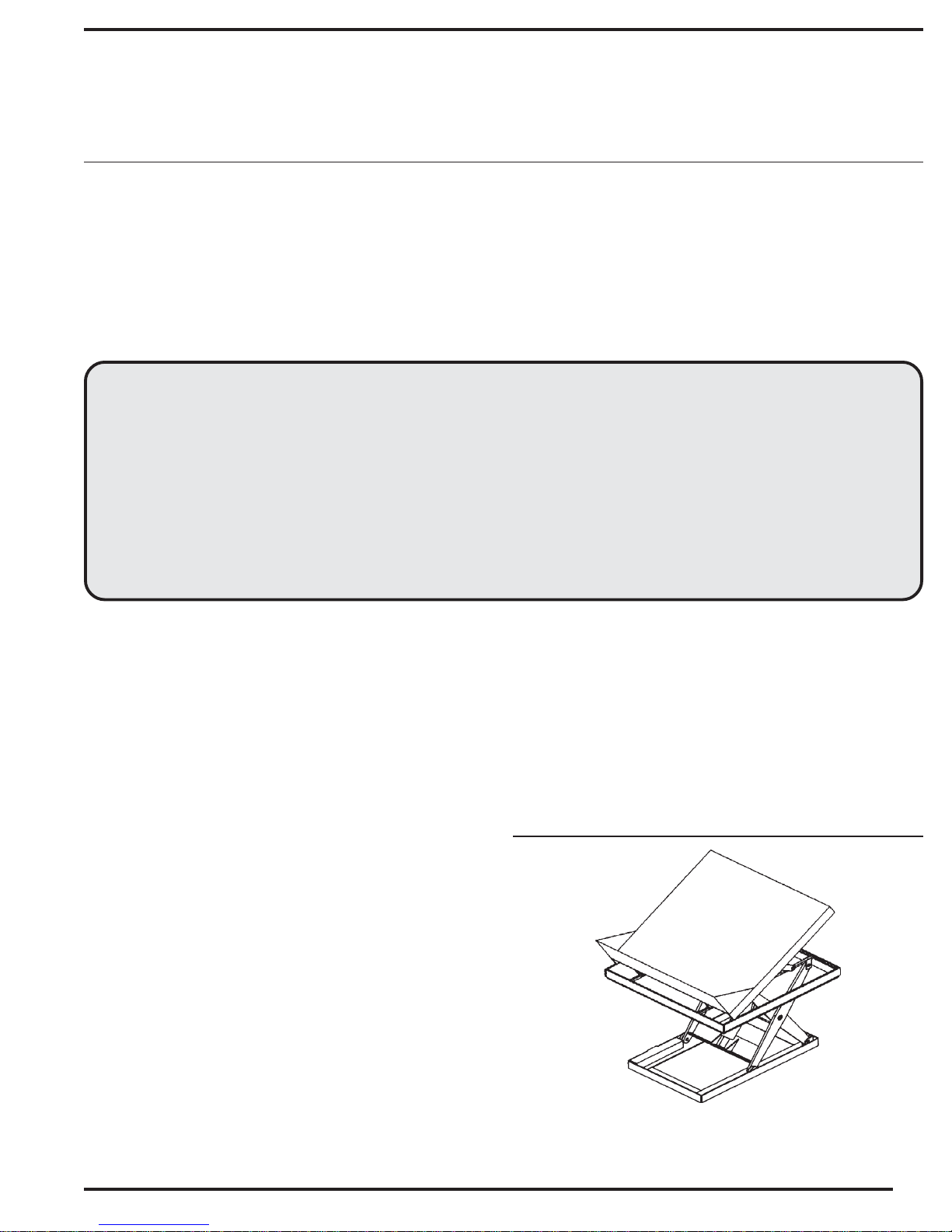
LIFT & TILT SCISSOR TABLE
SERIES EHLTT
Periodic Maintenance Instructions ................... 8
Trouble Shooting Guide ..............................9-10
Exploded Parts Drawing ................................ 11
Parts List ........................................................ 12
Warning Label Identification ........................... 13
Material Safety Data Sheets ...................... 14-15
Warranty ......................................................... 16
Service Record............................................... 16
WARNINGS & SAFETY INSTRUCTIONS
Read owner's manual completely before operating unit!
• Not a personnel lift. Keep clear when operating
• Never go under platform if there is weight on unit.
• Remove weight before working on unit.
• Use only maintenance parts supplied or approved by the
manufacturer.
• Do not change pressure relief valve setting.
• Do not clamp cylinder in vise as you may distort barrel.
• Never operate lift unless you are watching it.
• Load lift as uniformly as possible.
• Consult factory for uneven loading.
• Do not continue to hold down the UP control if unit is not
raising.
• Relieve system pressure by holding DOWN button after
unit has come to rest.
• Consult factory if adding conveyor top or performing any
modification to the original equipment.
• Do not use hydraulic oils, brake fluids or jack oils.
Use AW-32 Hydraulic Oil.
• Make sure all operator safety labels are in place.
RECEIVING INSTRUCTIONS
Every unit is thoroughly tested and inspected prior to
shipment. However, it is possible that the unit may incur
damage during transit. If you see damage when unloading
make a note of it on the SHIPPER RECEIVER.
Remove all packing and strapping material, inspect for
damage. IF DAMAGE IS EVIDENT, FILE A CLAIM WITH THE
CARRIER IMMEDIATELY! Also, check the unit size, type of
power unit, etc., to ensure the unit is correct for the intended
application.
MODEL NUMBER AND CAPACITY
The model number, serial number and capacities are
inscribed on the nameplate. Please remember to include these
numbers in any correspondence with you dealer or the factory.
LIFT & TILT SCISSOR TABLE
SERIES EHLTT
1

LOADING INSTRUCTIONS
SEQUENCE OF OPERATION
The load capacity rating as inscribed on the
nameplate of your unit designates the net capacity,
assuming the load is centered. This capacity must
never be exceeded, as permanent damage or injury
may result.
INSTALLATION TOOLS REQUIRED
A fork truck or some means to lift the table.
An adequately-sized power circuit with the specified
voltage, including a disconnecting means with fuses
or a circuit breaker. See the electrical section and
refer to the NEC and local codes.
INSTALLATION
• Check local codes for requirements pertaining to
your application.
• Blow out any hoses that arrive unconnected in
order to remove any potential contamination.
• Set the machine in place with a fork truck, crane,
etc. (If it is to be pit-mounted, connect power to the
table and raise the platform before setting it into
the pit.)
This machine is furnished with a constantpressure, or dead-main, style push-button control.
Pressing the "LIFT RAISE" button will turn on the
power unit and cause the table to lift straight up. It
will continue to more as long as you hold the button
or until the lift reaches its maximum raised height.
When the button is released, the platform stops and
holds at that particular height.
Pressing the "LIFT LOWER" button
energizes the lowering solenoid's coil and lowers
the platform at a controlled rate of descent. Upon
releasing the button, the platform stops and holds at
that height.
Pressing the "TILT RAISE" button turns on
the power unit and causes the platform to slide in
toward the center of the table and tilt at the same
time. It will continue to tilt until the either the operator
releases the button or the platform reaches its
maximum tilt angle. When the button is released,
the platform stops and holds its position.
Pressing the "TILT LOWER" button also turns
on the power unit and causes the platform to tilt
down toward the horizontal position until either the
button is released or the platform is lowered to the
horizontal position.
• Connect the proper power supply to the table
using personnel qualified to work with electricity.
• Raise the platform to its full raised height using the
push-button control. Install the maintenance props
(one on each side of the frame) and lower the
platform using the push-button control until it rests
on the maintenance props.
• Anchor the frame to the floor using 1/2" concrete
anchors adequate for the floor on which the table
is resting. Shim or grout under the frame sides so
that the entire length of each frame side is
supported.
• Operate the lift through several cycles, verifying
that the "platform raised," "platform tilted," and
"platform level" limit switches all work properly.
Verify the operating of the perimeter pinch point
(toe) safety guard.
• Clean up any spilled oil or debris.
OPERATOR TIPS
• Read and understand all warning labels on the lift
before operating it.
• Stand clear and to the side of the unit when it is
moving.
• Don't use the lift if you suspect it is in need of
repairs or if it is malfunctioning.
• Notify maintenance personnel in the event that
you notice anything out of the ordinary, such as
binding, odd pump noises, etc.
• Don't continue to press either of the "LIFT" buttons
if the platform doesn't move. Doing so could cause
damage to the pump or motor.
2
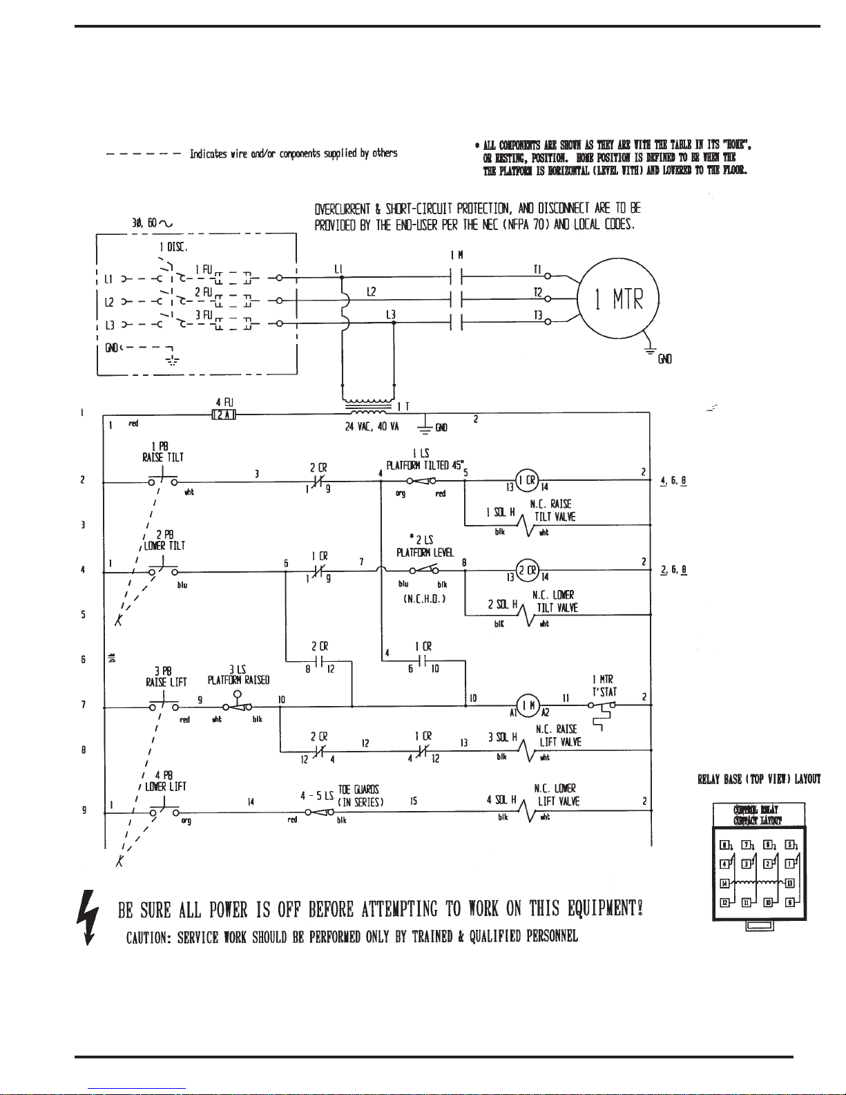
ELECTRICAL SCHEMATIC
3
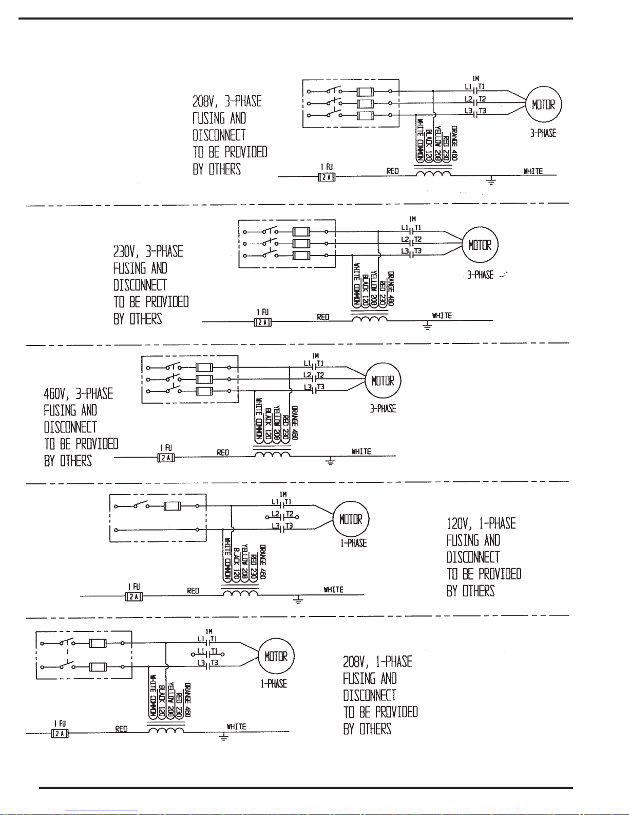
PRIMARY WIRING FOR CONTROL TRANSFORMER
4
POWER CONVERSION
5
 Loading...