

Page 1
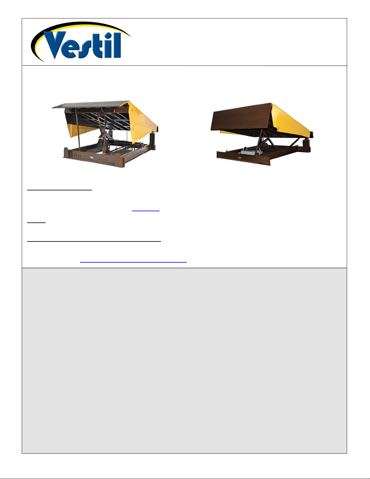
Table of Contents 11/5/2018 EH MANUAL
RR-Series & EH-Series Dock Leve lers
RR Series (Mechanical)
EH Series (Electric-Hydraulic)
TABLE OF CONTENTS
Limited Warranty………………………………………………………………………………………………………………….. 25
Vestil Manufac turing Corp.
2999 North Wayne Street, P.O. Box 507, Angola, IN 46703
Telephone: (260) 665-7586 -or- Toll Free (800) 348-0868
Instruction Manual
Receiving instructions:
After delivery, remove the packaging from the product. Inspect the product closely to determine whether it
sustained damage dur ing tr ans port . If damage is discovered, r ec ord a c omplete description of it on th e b il l of lad ing . If
the product is undamaged, discard the packaging
.
NOTE: The end-user is solely responsible for confirming that product design, use, and maintenance comply with
laws, regulations, codes, and mandatory standards applied where the product is used.
Replacement Parts and Technical Assistance:
For answers to questions not addressed in these instructions and to order replacement parts, labels, and
accessories, call our Technical Service and Parts Department at (260) 665-7586. The department can also be
contacted online at http://www.vestilmfg.com/parts_info.htm
.
Signal Words………………………………………………………………………………………………………….……………. 2
Hazards of Improper Use…………………………………………………………………………………………...…………….. 2
EH-65, EH-66, EH-68 and EH-610 Exploded View & Bill of Materia ls ……………………………………………………….. 3
EH-75, EH-76, EH-78 and EH-710 Exploded View & Bill of Materials……………………………………………………….. 4
Power Unit Exploded View and Bill of Materials [EH-65; EH-66; & EH-68]………………………………………………….. 5
Power Unit Exploded View and Bill of Materia ls [EH-610; EH-75; EH-76; EH-78; & EH-710]…………………………….. 6
Manifold Exploded View and Bill of Materials [EH-65; EH-66; & EH-68]…………………………………………………….. 7
Manifold Exploded View and Bill of Materials [EH-610; EH-75; EH-76; EH-78; & EH-710]……………………………….. 7
Electrical Circuit Diagram, 115V AC, 1-Phase [EH Dock Levelers]..……………………………………..………………….. 8
Electrical Circuit Diagram, 208-230V AC, 1-Phase [EH Dock Levelers]……...……………………………………………… 9
Electrical Circuit Diagram, 3-Phase AC [EH Dock Levelers]………………………………………………………………….10
Electrical System Operation [EH Dock Levelers]..……………………………………………………………...…………….. 11
Hydraulic Circuit Sequence of Operation [EH Dock Levelers]……………………………………………………………….. 11
Adjusting Hydraulic Settings [EH Dock Levelers]…………………………………………………………………….............. 12
RR-65, RR-66, RR-68, and RR-610 Exploded View and Bill of Materials…………………………….………………. 13 - 14
RR-75, RR-76, RR-78, and RR-710 Exploded View and Bill of Materials…………………………………………….. 15 - 16
Installation…………………………………………………………………………………………………………………………. 17
Operation: EH Series………………..…………………………………………………………………………………....17, 18, 19
Operation: RR Series…………………………………………………………………………………………………………….. 19
Troubleshooting: EH-Series…………………...…………………………………………………………………………........... 20
Inspections and Maintenance: EH-Series………………………………...……………………………………………………. 21
Inspections and Maintenance, RR-Series………………………………………………………………………………........... 22
Adjusting Spring Tension: RR -Series…………………………………………………………………………………………… 23
Labeling Diagrams: RR-Series and EH-Series………..………………………………………………………………………. 24
Table of Contents Copyright 2018 Vestil Manufacturing Corp. Page 1 of 25
Page 2
Table of Contents 11/5/2018 EH MANUAL
Signal Words:
This manual uses SIGNAL WORDS to indicate the likelihood that a particular action will cause
personal injuries or
product is misused in the ways
Identifies a hazardous situation which, if not avoided, COULD result in DEATH or
Indicates a hazardous situation which, if not avoided, COULD result in MINOR or
Identifies actions likely to result in product/property damage, such as operation that might
property damage. Signal words also specify the level of seriousness of injury if the
SERIOUS INJURY.
MODERATE injury.
damage the product.
described. The following signal words are used in this manual.
Hazards of Improper Use:
Vestil strives to identify foreseeable hazards associated with the use of its products. However, material
handling is dangerous and no manual can address every conceivable risk. The end-user ultimately is
responsible for exercising sound judgment at all times.
If this product is used or maintained improperly serious personal injuries or death might r esult.
ALWAYS use the product properly.
• Failure to read and understand the entire manual before assembling, using or servicing the product
constitutes misuse.
• Read the manual to refresh your understanding of proper use and maintenance procedures whenever
necessary.
• DO NOT attempt to resolve any issue with the product unless you are certain t hat it will be safe to use
afterwards.
• DO NOT modif y the product in any way. Unauthorized modifications might make the lifter unsafe to use
and automatically void the Limited Warranty (see p. 25).
• DO NOT exceed the capacity of your unit. Capacity information appears on the product in label 287. The
Labeling Diagrams on p. 24 indicates where to find label 287 on your dock leveler.
• Inspect the product according to the instructions on p. 21 & 22. Replace each part that is not in normal
condition. DO NOT use the product until it is fully restored to normal condition. ONLY use manufacturerapproved replacement parts.
• Cycle the deck all the way up and all the way down. Listen for unusual sounds as the deck rises and
lowers. Watch the deck for unusual movement.
• DO NOT u se the dock leveler unless all machine guards are in place.
• This product is NOT a personnel lift. DO NOT use it to lift or transport people.
• [Hydraulically actuated units] NEVER change the setting of the pressure relief valve.
• DO NOT use this device UNLESS all labels are in place, readable, and undamaged. See Labeling
Diagrams on. p.24.
Proper use, maintenance, and storage are essential for this product to function properly.
o Always use this product in accordance with the instructions in t his m anual and c onsist ent with any training
relevant to machines, devices, etc. used in conjunction with this product.
o Keep the product clean & dry. Periodically lubricate moving parts.
o FOR HYDRAULIC UNITS: Do not use brake fluid or jack oils in the hydraulic system. If oil is needed, use
an anti-wear hydraulic oil with a viscosity grade of 150 SUS at 100°F, (ISO 32 cSt @ 40°C), or Dexron
transmission fluid.
o Contact the manufacturer for SDS information
Table of Contents Copyright 2018 Vestil Manufacturing Corp. Page 2 of 25
Page 3
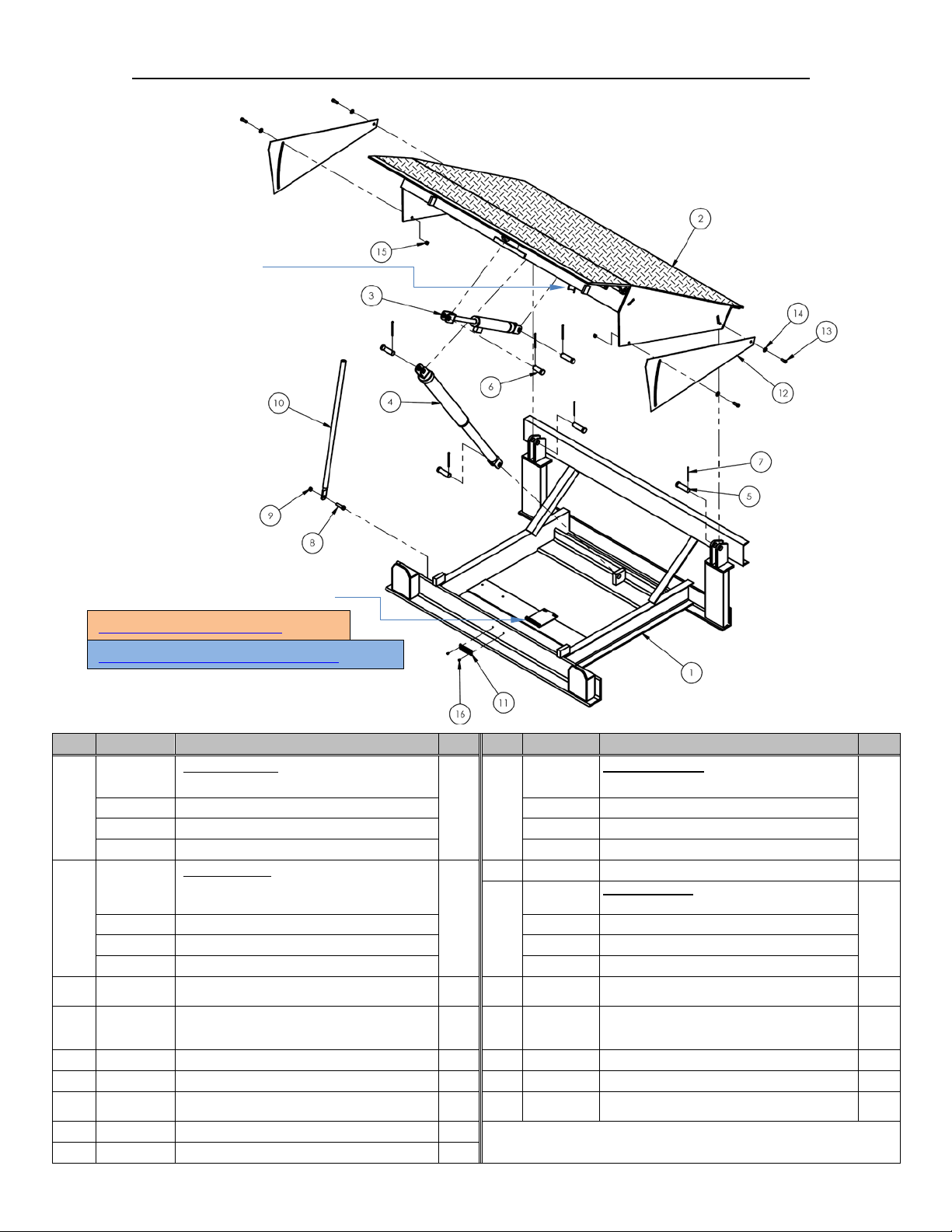
Table of Contents 11/5/2018 EH MANUAL
Item
Part no.
Description
Item
Part no.
Description
11
1
06-024-015
Guard, side skirt
EH-65
99-021-933-
001
Cylinder, hydraulic, 2” x 8” piston style with
clevis mounts
06-521-002
Assembly, cylinder, hydraulic:
EH-610: 21/2” x 18”
5
5
15
2
6
1
16
2
Extended prong cotter pin, zinc finish, 3/16” x
31/2”
8
1
9
1
Power unit installs on this bracket.
Maintenance prop socket
Power Unit Exploded View on p. 5
EH-610 Power Unit Exploded View on p. 6
EH-65, EH-66, EH-68 and EH-610 Exploded View and Bill of Materials
Frame Weldment
06-514-001 EH-65
06-514-003 EH-66 06-014-013 EH-66
1
06-514-005 EH-68 06-014-011 EH-68
06-514-007 EH-610 06-014-015 EH-610
Deck Weldment
06-513-020 EH-65
2
06-513-023 EH-66 06-024-015 EH-66
06-513-026 EH-68 06-024-013 EH-68
06-513-029 EH-610 06-024-016 EH-610
3
06-521-001
4
47-112-001 Pin, clevis, 1” x 31/4”
06-112-014 Pin, clevis, 1” x 21/2”
7
65132
11211 Bolt, HHCS, 1/2”-13UNCx2”, zinc plated
36109 Hex nut, gr. A, plain finish, 1/2”-13
Table of Contents Copyright 2018 Vestil Manufacturing Corp. Page 3 of 25
EH-65; EH-66; and EH-68: 2” x 18”
Qty.
06-014-013
1 10
99-134-003 Tag, Model no., capacity, serial no.
1
12
1 13
1 14
6 *17
11107 Hex bolt, gr. A, zinc finish, 3/8”-16 x 11/4”
33008 Flat washer, low carbon, USS, zinc plated, 3/8”
37024 Nylon insert lock nut, gr. 2, zinc finish, 3/8”-16
51441 Star pin anchor, 3/16” x 3/16”
29-001-251 Bumper, laminated dock, 4.5” x 10.25” x 10”
*Not shown in diagram
Maintenance Prop
EH-65
Qty.
1
2
4
4
2
Page 4
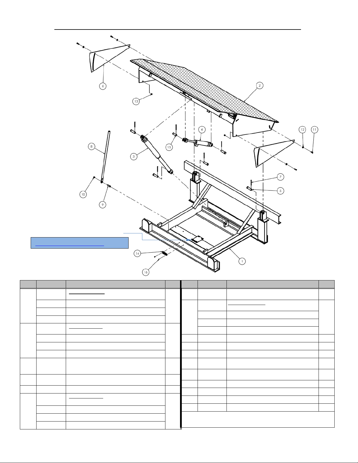
Table of Contents 11/5/2018 EH MANUAL
Item
Part no.
Description
Qty.
06-514-002
Weldment, frame
EH-75
06-513-120
Weldment, d eck
EH-75
06-521-002
Assembly, cylinder, hydraulic:
EH-710: 21/2” x 18”
99-021-933-
001
Cylinder, hydraulic, 2” x 8” piston style with
clevis mounts
5
5
Guard, side skirt
EH-75
Item
Part no.
Description
Qty.
Extended prong cotter pin, zinc finish, 3/16”
x 31/2”
06-014-013
Maintenance prop
EH-75
9
1
10
1
11
4
Flat washer, low carbon, USS, zinc plated,
/8”
Nylon insert lock nut, gr. 2, zinc finish, 3/8”16
14
1
15
1
16
2
*17
2
Power Unit Exploded View on p. 6
Power unit installs on this bracket.
EH-75, EH-76, EH-78 and EH-710 Exploded View & Bill of Materials:
06-514-004 EH-76
1
06-514-006 EH-78
06-514-008 EH-710
06-513-123 EH-76
2
06-513-126 EH-78
06-513-129 EH-710
3
06-521-001
EH-75; EH-76; and EH-78: 2” x 18”
4
47-112-001 Pin, clevis, 1” x 31/4”
06-024-015
06-024-015 EH-76
6
06-024-013 EH-78
06-024-016 EH-710
Table of Contents Copyright 2018 Vestil Manufacturing Corp. Page 4 of 25
7
65132
6
1
06-014-013 EH-76
8
06-014-011 EH-78
06-014-015 EH-710
1
12
1
13
1
2
* Not shown in diagram
11211 Bolt, HHCS, 1/2”-13UNCx2”, zinc plated
36109 Hex nut, gr. A, plain finish, 1/2”-13
11107 Hex bolt, gr. A, zinc finish, 3/8”-16 x 11/4”
33008
37024
99-134-003 Tag: model no. capacity, serial no.
06-112-014 Pin, clevis, 1” x 21/2”
51441 Star pin anchor, 3/16” x 3/16”
29-001-251 Bumper, laminated dock, 4.5”x10.25”x10”
3
1
4
2
Page 5
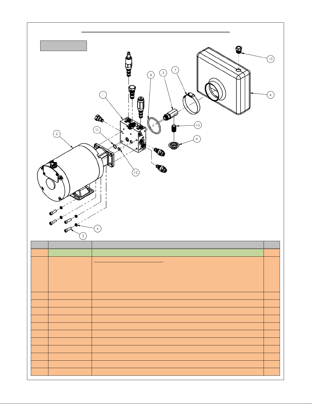
Table of Contents 11/5/2018 EH MANUAL
Power Unit Exploded View and Bill of Materials
Item
Part no.
Description
Qty.
99-137-008-002
Motor-and-Pump subassembly:
208-230V AC, 1-phas e, 0.7 5H P, 172 5rpm, 0.073 displacem ent
1
3
99-116-001
Suction fitting, mini-manifold
1
5
23255
5
/16”-18 x 1” socket head cap screw
4
9
99-031-029
Accessories, hydraulic
1
10
01-116-003
Breather, 1/2” NPT
1
11
99-144-009
O-ring, manifold, 3/4” outer diameter
1
12
99-144-008
O-ring, manifold, 1/2” outer diameter
1
13
99-031-033
Accessories, nipple, close pipe
1
Return to Page 3
EH-65, EH-66, & EH-68
1 06-627-003 Subassembly, Manifold, Lift-Lower, Double Acting LIP (detail view on p. 7) 1
99-137-033-003
99-137-033-004
2
99-137-013-002
99-137-008-001
4 33687 Lock washer, high collar, 5/16” 4
6 06-023-003 Hydraulic tank 1
7 99-145-061 Clamp, worm gear hose, 213/16” – 33/4” 1
8 99-144-007 O-ring, manifold, 3” outer diameter 1
208-230V AC, 3-phase, 2HP, 3450rpm, 0.180 displacement
460V AC, 3-phase, 2HP, 3450rpm, 0.180 displacement
208-230V AC, 1-phase, 2HP, 3450rpm, 0.122 displacement
115V AC, 1-phase, 0.75HP, 1725rpm, 0.073 displacement
1
1
1
1
Table of Contents Copyright 2018 Vestil Manufacturing Corp. Page 5 of 25
Page 6
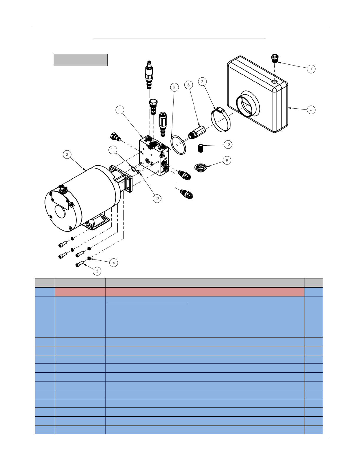
Table of Contents 11/5/2018 EH MANUAL
Power Unit Exploded View and Bill of Materials
Item
Part no.
Description
Qty.
1
06-627-004
Subassembly, Manifold, Lift-Lower, Double Acting LIP (detail view on p. 7)
1
99-137-008-002
Motor-and-Pump subassembly:
208-230V AC, 1-phase, 0.7 5HP, 172 5r pm, 0.073 displacement
1
3
99-116-001
Suction fitting, mini-manifold
1 4 33687
Lock washer, high collar, 5/16”
4 5 23255
5
/16”-18 x 1” socket head cap screw
4 6 06-023-003
Hydraulic tank
1 7 99-145-061
Clamp, worm gear hose, 213/16” – 33/4”
1 8 99-144-007
O-ring, manifold, 3” outer diameter
1
12
99-144-008
O-ring, manifold, 1/2” outer diameter
1
Return to Page 4
99-137-033-003
99-137-033-004
2
99-137-013-002
99-137-008-001
9 99-031-029 Accessories, hydraulic 1
10 01-116-003 Breather, 1/2” NPT 1
11 99-144-009 O-ring, manifold, 3/4” outer diameter 1
13 99-031-033 Accessories, nipple, close pipe 1
EH-610, EH-75, EH-76, EH-78, & EH-710
208-230V AC, 3-phase, 2HP, 3450rpm, 0.180 displacement
460V AC, 3-phase, 2HP, 3450rpm, 0.180 displacement
208-230V AC, 1-phase, 2HP, 3450rpm, 0.122 displacement
115V AC, 1-phase, 0.75HP, 1725rpm, 0.073 displacement
1
1
1
1
Table of Contents Copyright 2018 Vestil Manufacturing Corp. Page 6 of 25
Page 7
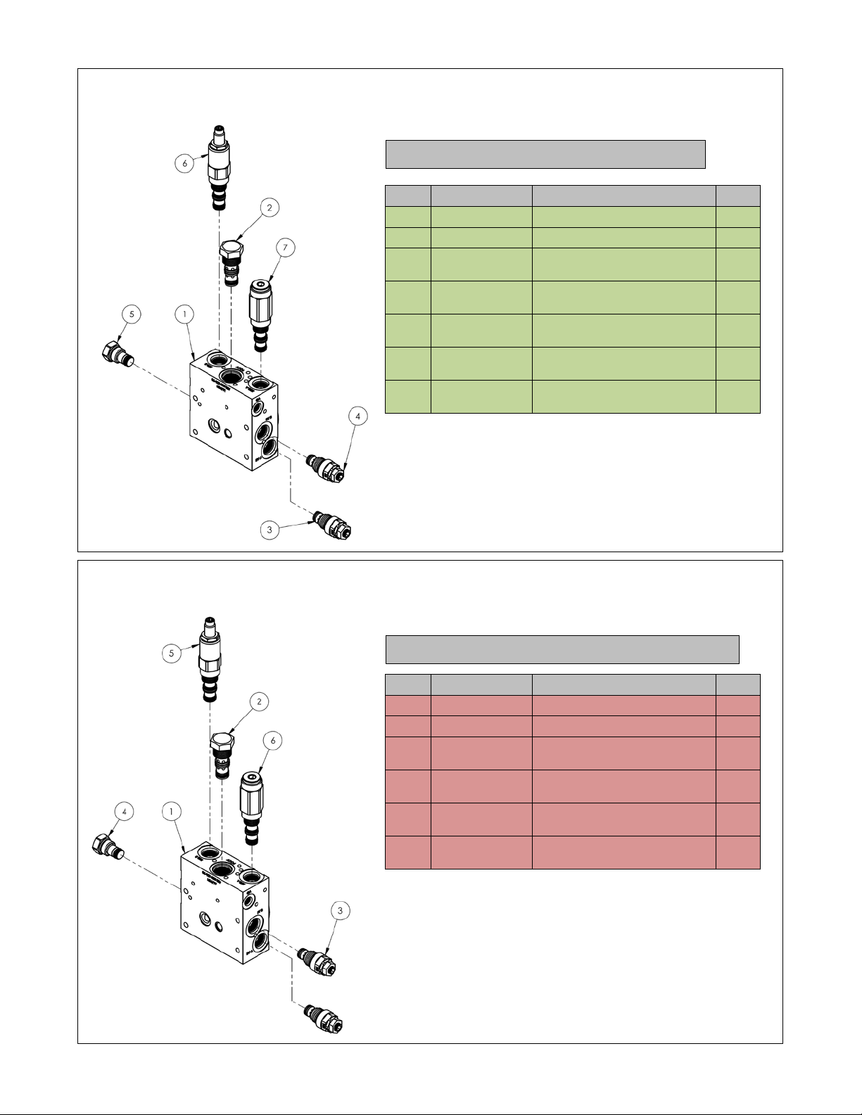
Table of Contents 11/5/2018 EH MANUAL
Manifold Exploded View (06-627-003):
Manifold Exploded View (06-627-004):
Item
Part no.
Description
Qty.
Valve pressure relief, 100
bar
Valve, pressure relief, 33
bar
Check valve, size 08, nose
inside-out
Cartridge valve, sequence,
3-way, adjustable
Cartridge valve, sequence,
2-way with pilot
Item
Part no.
Description
Qty.
1
06-127-005
Manifold, hydraulic
1 2 99-153-020
Pilot-to-close check valve
1
Valve pressure relief, 100
bar
Check valve, size 08, nose
inside-out
Cartridge valve, sequence,
3-way, adjustable
Cartridge valve, sequence,
2-way with pilot
Return to Power Unit Explo ded View on Page 5
Return to Power Unit Explo ded View on Page 6
EH-65; EH-66; & EH-68
1 06-127-005 Manifold, hydraulic 1
2 99-153-020 Pilot-to-close check valve 1
EH-610; EH-75; EH-76; EH-78, & EH-710
3 99-153-004
4 99-153-005
5 99-153-011
6 99-153-054
7 99-153-055
1
1
1
1
1
Table of Contents Copyright 2018 Vestil Manufacturing Corp. Page 7 of 25
3 99-153-004
4 99-153-011
5 99-153-054
6 99-153-055
2
1
1
1
Page 8
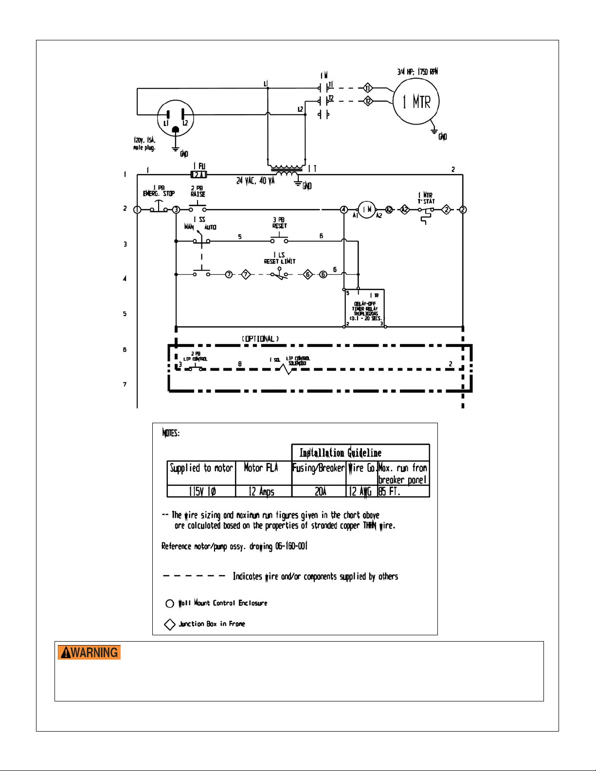
Table of Contents 11/5/2018 EH MANUAL
EH Dock Leveler Electrical Circuit Diagram, 115VAC, 1-phase (06-124-029 rev. B)
The end-user mus t provide overcurrent and short cir cuit protection compliant with NEC guidelines and loc al
codes.
Turn off all sources of electrical power and lock and tag them out before beginning this
installation.
might be added in the future, such as dock locks and lights.
Always turn off all power sources before beginning work on this equipment.
2in. conduit is recommended for this installation to allow adequate room for auxiliary equipment that
Table of Contents Copyright 2018 Vestil Manufacturing Corp. Page 8 of 25
Page 9

Table of Contents 11/5/2018 EH MANUAL
EH Dock Leveler Electrical Circuit Diagram, 208-230VAC, 1-phase
Always turn off all power sources before servicing this equipment.
The end-user mus t provide overcurrent and short circuit prot ection compliant with NEC guidel ines and local
(06-124-030 rev. A)
Turn off all sources of electrical power and lock and tag them out before beginning this
installation.
might be added in the future, such as dock locks and lights.
codes.
Table of Contents Copyright 2018 Vestil Manufacturing Corp. Page 9 of 25
2in. conduit is recommended for this installation to allow adequate room for auxiliary equipment that
Page 10

Table of Contents 11/5/2018 EH MANUAL
EH Dock Leveler Electrical Circuit Diagram, 208, 230, & 460VAC, 3-phase
The end-user mus t provide overcurrent and short circuit prot ection compliant with NEC guidelin es and local
codes
(06-124-031 rev. A)
Turn off all sources of electrical power and lock and tag them out before beginning this
installation.
might be added in the future, such as dock locks and lights.
Always turn off all power sources before servicing this equipment.
Table of Contents Copyright 2018 Vestil Manufacturing Corp. Page 10 of 25
2in. conduit is recommended for this installation to allow adequate room for auxiliary equipment that
.
Page 11

Table of Contents 11/5/2018 EH MANUAL
Figure 4: Hydraulic circuit
Electrical system operation, EH Series
The electric circuit consists of a push-and-hold motor start circuit with thermal protection. The timer circuit
activates and runs the motor for approximately 10 seconds. The timer is actuated by either a limit switch in
automatic mode, or by pressing the RESET button in manual mode.
Hydraulic Circuit Sequence of Operation, EH Series [Numbers in Parentheses () Correspond to Nu mbers in
the Diagram Above]
EH-series dock levelers are hydraulically powered through a sequence of steps. The pressure required to raise
the deck varies with deck size. However, the pressure always remains below the pressure setting of the lip
sequence valve (6). The sequence valve is factory set to 7 00 PSI, unless the deck’s weight requires a different
setting, and should not be changed.
Pressing the “RAISE” button activates the pump. Oil pressure increases until it equals the cracking pressure of
the outlet check valve (3). The pressure closes valve (4), a pilot-to-close check valve with a 3:1 ratio. When the pilot
pressure exceeds one third of the inlet pressure, the valve closes. As pressure builds in the deck cylinder, the deck
rises and the lip rotates outward. When the pressure exceeds 40 PSI, the lip’s dump valve, (5), closes. The dump
valve is a normally open “pilot-to-close” directional valve.
As the lip rotates outward, oil from the cap end of the lip cylinder (12) is forced across the lip relief valve (2B).
The pressure setting of the lip relief valve divides oil flow between the deck cylinder (11) and the lip cylinder (12),
and controls the lip’s movement. If the pressure is too low, the lip will not fully extend. If pressure is too high, the lip
will retract too slowly and fail to return to its stowed position. The lip should completely rotate outward when the
deck rises approximately 18 inches.
After the deck cylinder fully extends, hydraulic pressure continues to increase until the lip sequence valve (6)
shifts. When the valve shifts, there is pressure on both sides of the lip cylinder. Because there is more pressure
applied to the cap end of the cylinder than to the rod end, the lip cylinder retracts.
Releasing the RAISE button deactivates the pump and the hydraulic pressure declines. When the pump output
pressure drops below one third of the lift pressure, the pilot-to-close check valve (4) opens and the deck begins to
descend. A pressure-compensated flow control valve (9) controls the deck’s rate of descent. Pressure continues to
decrease after the deck returns to its fully lowered position. When the pressure drops below 40 PSI, the lip d ump
valve (5) opens which allows the lip to return to its stowed position.
The hydraulic system includes a safet y device , called a velocity fuse, which prevents the deck from collapsing if
system pressure suddenly drops (for example, if the flow control valve fails or a hose is punctured). The fuse is
integrated into the cylinder. When the fuse closes oil cannot flow back to the reservoir.
Table of Contents Copyright 2018 Vestil Manufacturing Corp. Page 11 of 25
Page 12

Table of Contents 11/5/2018 EH MANUAL
Table of Contents Copyright 2018 Vestil Manufacturing Corp. Page 12 of 25
Page 13

Table of Contents 11/5/2018 EH MANUAL
RR-65, RR-66, RR-68 and RR-610 Exploded View (Bill of Materials on Following
Deck shock assembly (attached to underside of item 2)
Page)
Used on RR-66, RR-68, RR-610, RR-76, RR-78, & RR-710
Table of Contents Copyright 2018 Vestil Manufacturing Corp. Page 13 of 25
Page 14

Table of Contents 11/5/2018 EH MANUAL
Base frame weldment
07-514-002
RR-65
07-514-003
RR-66
07-514-004
RR-68
07-514-005
RR-610 2
Deck assembly
06-513-020
RR-65
06-513-021
RR-66
06-513-022
RR-68
06-513-023
RR-610
3
07-518-006
Weldment, standard trunnion
1
20
07-112-019
Clevis pin, 3/4” x 23/4”
1
4
07-042-001
D-comp ratchet
1
21
99-117-005
2” diameter x 1/4” steel ring
1
5
07-527-014
Subassembly, chain roller bearing
1
22
06-014-011
Frame, mechanical prop
1
Spring, subassembly, 800 cam
RR-68 & RR-610
10
7
07-646-003
Subassembly, spring chain
1
24
99-145-050
Specialty hardware, S-hook
1
8
07-016-029
Counterbalance arm
1
25
36109
Hex nut, gr. A, plain finish, 1/2”-13
2
07-145-007
Screw, threaded rod
RR-65
Guard, side skirt
RR-65
07-145-007
RR-66
06-024-015
RR-66
07-145-011
RR-68
06-024-013
RR-68
07-145-012
RR-610
06-024-016
RR-610
10
33016
Flat washer, low carbon, USS, zinc plated, 5/8”
12
27
11107
Hex bolt, gr. A, zinc finish, 3/8”-16x11/4”
4
11
01-145-011
Specialty hardware, eyelet
1
28
33008
Flat washer, low carbon, USS, zinc plated, 3/8”
4
12
5546062
Grease zerk, 3/16”, straight, drive-in
2
29
99-145-013
Cold shut
3
13
47-112-001
Clevis pin, 1” x 31/4”
4
30
99-134-003
Data tag (model, capacity, serial no.)
1
14
28-112-031
3
/4” x 41/2” clevis pin
1
31
51441
Star pin anchor, 3/16” x 3/16”
2
99-145-113
Specialty hardware, chain, trunnion chain
RR-75
99-145-114
RR-76
99-145-115
RR-78
99-145-116
RR-710
07-145-014
Specialty hardware, pull chain
RR-75
07-145-015
RR-76
07-145-016
RR-78
07-145-017
RR-710
17
37024
Nylon insert lock nut, gr. 2, zinc finish, 3/8”-16
3
*34
29-001-251
Laminated dock bumper, 41/2” x 101/4” x 10”
2
* Not shown in diagram
Item
Part no.
Description
Qty.
36
1
37
1
38
2
39
2
40
1
41
4
42
1
43
2
44
1
45
3
46
2
47
1
RR-65, RR-66, RR-68 and RR-610 Bill of Materials
Item Part no. Description
Qty.
Item Part no. Description
1
1 18
1 19
6
07-646-001
RR-65
RR-66
6
8
9
6
15
65080 Extended prong cott er pin, zinc finish, 1/8” x 2”
2 32
16
11119 Hex bolt, gr. A, zinc finish, 3/8”-16 x 4”
1 *33
Table of Contents Copyright 2018 Vestil Manufacturing Corp. Page 14 of 25
07-016-065 Bracket, angle, li p rod
07-026-001 Shaft, lip adjust i ng rod
07-016-001 Bracket, shock absorber, formed
07-016-036 Bracket, l i p adjust6i ng rod, form ed
07-146-007 Spring, pl unger
33011 Flat washer, USS, plain finish, 1/2”
23-112-024 Pin , clevis, 1/2” x 6”
07-146-011 Spring/s hock absorber
36219 1” – 8 plain finish hex jam nut
65080 Extended prong cotter pin, zinc finish, 1/8” x 2 “
28-112-040 Clevis pin, 1/2” x 2”
33446 10Ga machine bushing, 1” x 18ga.
07-146-006 Spring, lip retainer
65132
07-145-018 D-comp limit chain
23
06-024-015
Extended prong cotter pin, zinc finish,
1
3
/2”
26
Qty.
1
3
/16” x
4
1
2
1
1
Page 15

Table of Contents 11/5/2018 EH MANUAL
RR-75, RR-76, RR-78 and RR-710 Exploded View (Bill of Materials On Following
Deck shock assembly (attached to underside of item 2)
Page)
Used on RR-66, RR-68, RR-610, RR-76, RR-78, & RR-710
Table of Contents Copyright 2018 Vestil Manufacturing Corp. Page 15 of 25
Page 16

Table of Contents 11/5/2018 EH MANUAL
07-514-006
RR-75
07-514-008
RR-78
Deck assembly
06-513-041
RR-76
06-513-043
RR-710
3
1
20
1
4
07-042-001
D-comp ratchet
1
21
99-117-005
2” diameter x 1/4” steel ring
1
5
1
22
1
6
07-646-001
Spring, subassembly, 800 cam
10
23
07-145-018
D-comp limit chain
1
7
1
24
1
8
07-016-029
Counterbalance arm
1
25
36109
Hex nut, gr. A, plain finish, 1/2”-13
2
07-145-007
Screw, threaded rod
RR-75
06-024-015
Guard, side skirt
RR-75
07-145-007
RR-76
06-024-015
RR-76
07-145-011
RR-78
06-024-013
RR-78
10
20
27
4
11
01-145-011
Specialty hardware, eyelet
1
28
33008
Flat washer, low carbon, USS, zinc plated, 3/8”
4
12
5546062
Grease zerk, 3/16”, straight, drive-in
2
29
99-145-013
Cold shut
3
13
4
30
1
14
1
31
2
99-145-113
Specialty hardware, chain, trunnion chain
RR-75
RR-76
RR-78
07-145-014
Specialty hardware, pull chain
RR-75
RR-76
RR-710
Nylon insert lock nut, gr. 2, zinc finish, 3/8”-16
RR-75
RR-76, RR-78, & RR-710
5
* Not shown in diagram
Item
Part no.
Description
Qty.
36
1
37
1
38
2
39
2
40
1
41
4
42
1
43
2
44
1
45
3
46
2
47
1
RR-75, RR-76, RR-78 and RR-710 Bill of Materials
Item Part no. Description
Base frame weldment
07-514-007 RR-76
1
07-514-009 RR-710
06-513-040 RR-75
2
06-513-042 RR-78
07-518-006 Weldment, standard trunnion
07-527-014 Subassembly, chain roller bearing
07-646-003 Subassembly, spring chain
9
07-145-012 RR-710 06-024-016 RR-710
33016 Flat washer, low carbon, USS, zinc plated, 5/8”
Qty.
Item Part no. Description
1 18
1 19
07-146-006 Spring, lip retainer
65132
07-112-019 Clevis pin, 3/4” x 23/4”
06-014-011 Frame, mechanical prop
99-145-050 Specialty hardware, S-hook
10 26
11107 Hex bolt, gr. A, zinc finish, 3/8”-16x11/4”
Extended prong cotter pin, zinc finish,
1
3
/2”
3
/16” x
Qty.
1
4
2
47-112-001 Clevis pin, 1” x 31/4”
28-112-031 3/4” x 41/2” clevis pin
15
16
17
65080 Extended prong cott er pin, zinc finish, 1/8” x 2”
11119 Hex bolt, gr. A, zinc finish, 3/8”-16 x 4”
37024
99-134-003 Data tag (model, capacity, serial no.)
51441 Star pin anchor, 3/16” x 3/16”
2 32
R-710
1 *33
RR-78
3
07-016-065 Bracket, angle, li p rod
07-026-001 Shaft, lip adjust i ng rod
07-016-001 Bracket, shock absorber, formed
07-016-036 Bracket, li p adjust6ing rod, f orm ed
07-146-007 Spring, pl unger
33011 Flat washer, USS, plain finish, 1/2”
23-112-024 Pin , clevis, 1/2” x 6”
07-146-011 Spring/s hock absorber
36219 1” – 8 plain finish hex jam nut
65080 Extended prong cotter pin, zinc finish, 1/8” x 2 “
28-112-040 Clevis pin, 1/2” x 2”
33446 10Ga machine bushing, 1” x 18ga.
29-001-251 Laminated dock bumper, 41/2” x 101/4” x 10”
*34
1
1
2
Table of Contents Copyright 2018 Vestil Manufacturing Corp. Page 16 of 25
Page 17

Table of Contents 11/5/2018 EH MANUAL
The Dock Leveler must be level to function properly.
Do not modify the dock leveler to fit in a pit.
NOTE:
Pit bottom
should slope
¼ in. The
rear wall pit
depth should
be 24¾in.
Never work under a dock leveler unless the maintenance prop is installed in its socket.
1. Measure the pit’s dimensions.
2. Using steel shims, position shims under the
frame to prevent frame distortions and flex so
the Dock Leveler’s final, resting position meets
the following:
• The Dock Leveler should be level.
• The Dock Leveler should be against the
rear pit curb angle.
• The platform should be centered from side
to side within the pit.
• The Dock Leveler’s rear channel must be
flush with the rear curb angle.
Do not allow the Dock Leveler
to be above the pit’s rear curb
angle.
3. With the shims in position, skip weld the rear
hinge channel to the rear curb angel, 4 inches
every 8 inches.
4. Grind welds smooth.
Operation, EH Series
The Dock Leveler has an electric motor directly
coupled to a gear-type hydraulic pump to
pressurize the hydraulic system. Hydraulic
pressure allows the cylinders to lift the platform
and extend the lip. The hydraulic control
components are housed within a hydraulic
manifold, bolted directly onto the gear pump. All
hydraulic components are rated for 3,000 psi
working pressure.
Notable power unit parts include:
1. Electric motor: The A/C motor operates on either single-phase or 3-phase AC, depending on the motor
ordered.
2. Gear pump: The pump shaft is coupled directly to the electric motor shaft.
3. Pressure relief valve: At pressures greater than 1,500 psi, fluid flows back into the reservoir.
4. Lip relief valve: The adjustable valve controls the Lip’s retr ac t rate after the platform has risen.
5. Check valve: It prevents fluid backflow through the pump.
6. Pilot-operated check valve: This valve is closed while the leveler rises and it opens when the pilot pressure
drops to less than 1/3 of the inlet pressure, causing the deck to descend.
Table of Contents Copyright 2018 Vestil Manufacturing Corp. Page 17 of 25
Installation
Page 18

Table of Contents 11/5/2018 EH MANUAL
7. Pilot-to-close, two-position va lv e: Normally open, this valve closes when the pilot pressure exceeds 40 psi.
It holds the lip in the extended position until either the platform or the lip is physically supported.
8. Pilot-operated sequence valve: When system pressure reaches ~700 psi, the valve shifts to extend the lip.
9. Pressure-compensated flow control valve: Located in the deck cylinder’s port, it regulates the deck’s lowering rate.
10. Hydraulic cylinders:
a. Deck cylinder - A displacement-style cylinder with a bleeder valve located at the top end raises and
lowers the deck. The bleeder valve allows air to be removed from the hydraulic system.
b. Lip cylinder - A double-acting cylinder extends and retracts the Lip.
11. Safety velocity fuse: Located in the deck cylinder’s hose port, it closes quickly in the event of a catastrophic
hose failure to prevent the deck from collapsing. The deck remains elevated until pressure is reapplied to
the cylinder.
12. Hydraulic fluid: The system uses HO150 hydraulic fluid. Any anti-wear hydraulic oil with a viscosity grade of
150 SUS at 100°F (ISO 32 at 40°C), such as: AW 32 or a non-synthetic transmission fluid is acceptable.
Pressing the RAISE button activ ates t he dock leveler. The motor turns and spins the hydraulic gear pump. Oil is
drawn from the reservoir through the suction filter and into the pump. The pump forces pressurized oil through the
hydraulic manifold to the deck cylinder. Pressure first acts on the deck cylinder causing it to extend, and then,
causes the lip cylinder to extend. When the RAISE button is released, the lip remains extended and the deck
descends at a rate determined by the pressure-compensated flow control valve. The lip eventually rests on the back
end of the trailer. If the deck descends and contacts the supporting frame, a limit switch is engaged. When in
“AUTO” mode, the limit switch causes the leveler to reset itself to the resting/cross-traffic position by turning on the
motor for approximatel y 3 seconds. This brief period is long enough to raise the deck and retract the lip. If the unit
is in “MANUAL” mode, engaging the limit switch only causes the lip to drop.
Issues & Solutions: additional solutions are found under Inspections and Maintenance.
Before beginning work to resolve either of the issues identified below, unload t he dock leveler and apply the
maintenance prop. To install the prop, press and hold the RAISE button. Continue to hold the button after the deck
reaches its maximum elevation. A second person should install the free end of the maintenance prop into the socket
on the underside of the deck. Release the RAISE button to allow the maintenance prop to seat firmly in the socket.
1. If the deck does not rise while the pump runs, remove the pilot-to-close check valve. Inspect and clean the
valve in the following manner:
a) Locate the pilot-to-close check valve, which is identified with the number “4” on the hydraulic manifold, and
remove it from the manifold.
b) Inspect the valve for contaminants. Also inspect the o-rings and back-up washers for cuts, tears, or other damage.
c) Immerse the valve in mineral spirits or kerosene. Use a thin tool, like a small screwdriver or a small hex wrench,
to push the check ball in several times from the bottom end of the valve. The ball should move freely. If it sticks
in, the valve might be defective. Replace the valve if the ball still does not move freely after cleaning. Blow the
valve off with compressed air, while simultaneously pushing the chec k ball in-and-out.
d) Inspect the bottom of the valve cavity in the manifold (the chamber in the manifold that houses the valve) for
debris. Clean the valve cavit y as needed .
e) Reinstall the valve. Tighten the valve in the manifold to approxim atel y 20 lb-ft of torque.
2. If the platform lowers extremely slowly, or not at all, the velocity fuse of the deck cylinder might be closing.
This is typically caused by air in the cylinder. To correct the problem, bleed air from the hydraulic system:
a) Hold a rag over the bleeder valve of the deck cylinder. The valve looks like a grease zirk. Use a ¼ in.
wrench to turn the valve about 1/2 turn. Jog the motor by quickly pressing and releasing the RAISE button.
Oil and air will sputter from the valve. Continue this process until air no longer escapes from the valve; then
close the valve.
Modes of Operation, EH Series
The leveler can be operated in either of two modes—automatic or manual. Before using the leveler, confirm normal
operation by running the leveler through a complete cycle:
1) Automatic mode: Press and hold the “RAISE” button on the remote control box. The deck will rise to its maximum
elevation and then the lip will extend. When the lip fully extends, release the “RAISE” button. The deck should
Table of Contents Copyright 2018 Vestil Manufacturing Corp. Page 18 of 25
Page 19

Table of Contents 11/5/2018 EH MANUAL
lower smoothly until the lip rests on the truck bed. The deck will descend to the fully lowered configuration when the
truck pulls away from the dock leaving the lip unsupported. The power unit will restart and raise the deck to
maximum elevation; the lip will lower; the power unit will shut off; and the deck will settle in to its stored position flush
with the surrounding surface.
DO NOT operate the dock leveler in automatic mode if the truck bed is below the level of the dock.
2) Manual mode: Use the leveler in this mode if a truck bed is below dock level. In manual mode, the dock leveler
functions nearly identically to automatic mode. However, the power unit does not automatically start to return the
deck to the stored position when the leveler reaches the lower limit. Instead, after a truck leaves the deck descends
to its fully lowered position and the lip drops to avoid being damaged by the next truck.
“RESET” button: press the button to automatically return the leve ler to the stored position while in manual mode.
3) To put the leveler into stored configuration, from either manual or automatic mode, while a truck occupies the
loading dock:
a) Press and hold the “RAISE” button until the deck reaches its maximum elevation;
b) Release the button;
c) The leveler will return to its stored position.
4) (Optional) Lip control: “LIP” button on the remote control extends the lip. First, press the “RAISE” button to
elevate the deck sufficiently that the lip will not contact the back of the truck as it extends; then press the “LIP” button
to extend the lip. Release the “RAISE” and “LIP” buttons and the lip will settle on the bed of the truck. If the RAISE
button is released but you continue to hold the LIP button, the leveler will maintain its position. Release the LIP
button to allow the lip to settle on the truck bed.
5) Emergency stop button: Pressing this button cuts all power to the unit. If the emergency stop button is
pressed at any time during the cycle of operation, the leveler will return to its stored position. Pull out the
emergency stop button to reset the switch and restore power.
Operation, RR Series
Do not leave any cargo or equipment on the Dock Leveler deck at any time.
Before Use
1. When the truck is against the Dock Lever’s bumpers, chock the truck’s wheels on both sides.
2. Verify the truck’s cargo area has ample room to accept the Dock Leveler lip. The lip will require about twelve
inches (12”) beyond the bumper for the standard sixteen inch (16”) lip.
3. If the cargo area is not sufficiently clear, clear the area.
4. Verify the lip is in the vertical position and securely behind the lip keepers.
Verify the people and equipment are clear of the leveler. The deck will rise and the lip will
automatically extend into the trailer.
5. If the deck is below dock height, release the pull and raise the deck a few inches above the dock floor.
6. Walk on the deck to lower it until the entire lip is setting on top of the trailer’s floor.
7. For Models with the ES Option: If the trailer floor is below the dock’s floor, the Emergency Stop’s safety legs
need to be retracted. Pull the ES ring, the rear-most ring on the Dock Leveler, to retract the safety legs and
completely lower the lip onto the trailer’s floor. Release the ES ring.
8. Load / unload the cargo.
After use
If the truck departs before the dock leveler is retracted, the lip will fall to the down position. The
lip might not be in the keep ers .
1. Pull the recessed handle, releasing the deck, until the lip clears the truck.
2. After the deck completely retracts, walk on the deck until it returns to floor height.
3. Verify the lip is behind the keepers.
4. The trailer’s overhead door and/or the buildin g m a y now be closed and the wheel c hoc ks rem oved.
Table of Contents Copyright 2018 Vestil Manufacturing Corp. Page 19 of 25
Page 20

Table of Contents 11/5/2018 EH MANUAL
Issue
Cause
Solution
Motor does not run and
1. Emergency stop button activated
7. Thermal-overload switch tripped
1. Pull up emergency stop button.
7. Wait for motor to cool.
Motor runs, but deck does
1. Motor rotation is wrong
lift its own weight)
1. Confirm that motor turns clockwise
Motor hums or pump
1. Excessive voltage drop to motor
6. Load applied to deck
1. Check power installation. Check
Deck does not automatically
1. Auto/Manual switch in manual
contact block
1. Move switch to “ a uto” pos it i on
Deck does not lower
1. Velocity fuse, item 10, in deck
valve stuck.
1. Press and release RAISE button to
Lip retracts too quickly
causing rough action
Lip relief valve, item #2B, pressure
setting too low
Turn adjustment on valve clockwise
(quarter turn or less)
Lip does not retract
Lip relief valve, item #2B, pressure
setting too high
Turn adjustment on valve
counterclockwise (quarter turn or less)
Lip retracts before
1. Lip relief valve, item #2B, pressure
3. Faulty power unit
1. Turn adjustment on valve clockwise
3. Repair or replace
Lip does not extend when
deck reaches top position
1. Defective lip cylinder
2. Faulty power unit
1. Repair or replace
2. Repair or replace
Troubleshooting, EH Series
The following information is provided to diagnose and correct issues with EH-series dock levelers.
deck does not rise
not rise and don’t hear
motor running
squeals but deck does not
rise or rises very slowly
(pressed)
2. Transformer fuse blown or tripped
circuit breaker
3. No supply voltage
4. Bad control transformer
5. Malfunctioning motor relay coil
6. Malfunctioning RAISE push button
2. Pumps failing to pressurize
hydraulic system
3. Load on the deck (leveler will only
because power cord wire size too
small, wire length too long, or incoming
voltage too low.
2. Motor running slowly, is hot, or lost
one phase (3-phase motors)
4. Pressure relief valve opening at full
system pressure.
5. Pilot-to-close check valve failing to
close
2. Replace fuse or reset circuit
breaker.
3. Test voltage with meter, Check
fuses, breakers, and overloads.
4. Check for 24VAC; replace if bad.
5. Test with meter; replace if bad.
6. Test with meter; replace if bad.
opposite the shaft end.
2. Contact the factory.
3. Unload the deck.
incoming voltage while motor running.
2. Check voltage on all legs; check
fuses; repair as necessary.
4. Check for frame damage or binding
at the deck hinge, etc. Check for
platform overload condition.
5. Remove valve and insp ec t.
6. Remove load from deck.
return to stored position
when truck leaves dock
contacting truck bed
position
2. Defective limit switch (deck fails to
engage the below dock limit switch, or
switch malfunctioning
3. Defective timer, or timer period set
too short
4. Bad (AUTO/Manual) selector switch
cylinder is locked.
2. Pressure-compensated flow control
setting too low
2. Faulty lip cylinder, item #12,
2. Change auto/manual switch to
Manual mode and press RESET
button.
3. Check the timer setting. Test for
timer output and replace if bad.
4. Test with meter; replace if bad.
unlock fuse. If problem persists, check
for air in oil.
2. Replace valve.
(quarter turn or less)
2. Repair or replace
Table of Contents Copyright 2018 Vestil Manufacturing Corp. Page 20 of 25
Page 21

Table of Contents 11/5/2018 EH MANUAL
Inspections and Maintenance: EH-Series
Before beginning maintenance, secure the deck in the raised configuration with the maintenance prop. The process
requires 2 people: one person presses and holds the RAISE button to keep the deck raised with the lip extended,
while the second person pivots the maintenance prop to align the free end of the prop with the socket on the
underside of the deck.
DO NOT use the Dock Leveler if adjustments and/or repairs are incom plete! Return it to service
ONLY after finishing all neces sary repairs and adjustm ents. The reader s hould understa nd the diff erence between
necessary adjustments and repairs, and modifications.
An adjustment is a simple correc tion that r es tores th e l i f ter to normal operating con dit ion, suc h as t ight en ing lo ose
fasteners, or removing dirt or other debris from the surface of the dumper; a repair refers to replacing w orn p ar ts with
new, factory-approved replacement parts.
A modification is a change that alters the m achine from norm al operating condition, like bending the struc tural
members or rem oving a part or several parts. NEVER modify the unit. Modifications automatically void the
Limited Warranty and might make the leveler unsafe to use.
Regu lar maintenance is essential to k eep the dock leveler o perating properl y. ONL Y use I SO AW -32
hydraulic fluid or its equal in the hydraulic system.
Inspections:
(A) Inspect daily for the following:
1.) Frayed wires and loose conduit fittings
2.) Damage and deformation of the structural members, cylinder brackets, etc.
3.) Run the leveler through a complete cycle. Listen for unusual noises and watch the leveler and lip for
binding or unusual movement, or evidence thereof, during operation.
4.) Confirm that the side skirt guards are securely fastened to the deck.
(B) Inspect the following each month:
1.) O il leaks – check the hoses, cylinders, fittings, etc. for oil leaks. Also check the oil level in the reservoir. Oil
should be 1” to 1½” below the fill hole in the reservoir. See Inspect ions and Ma int enanc e for oil specifications.
2.) Hydraulic hoses and electrical wiring - look for Worn or damaged hydraulic hoses and electrical wires.
3.) Hinge and cylinder pivot points – check for excessive wear at pivot points.
4.) Welds – check all welds for cracks and signs of metal fatigue, especially at the hinge.
5.) Mode functions – cycle the leveler through each mode (AUTO and Manual) to confirm proper functioning in
both modes. Carefully watch and listen to the leveler during operation. The leveler should operate without
unusual noises or movement.
5.) Limit switch – confirm normal operation of the below-dock limit switch in AUTO mode.
6.) Hardware – check all hardware/fasteners, especially pivot point pins and pin reta ini ng hard w are.
7.) Anchorage – closely examine the frame, anchor bolts, and the concrete around the anchor bolts for cracks,
warping, etc.
8.) Labels – confirm that each label is in place and in good condition.
9.) Leveler surfaces - clean dirt and debris from the surfaces of the leveler, especially debris under nea th and
around the power unit.
(C) Yearly Maintenance
NOTE: Usage and environment are significant factors affecting how frequently maintenance must be performed.
1.) Grease the lip hinge and all cylinder pivot points.
2.) The oil should be changed if the oil darkens, becomes gritty, or turns a milky color (indicating the presence
of water). Replace with anti-wear hydraulic oil with a viscosity grade of 150 SUS at 100°F, (ISO 32 at
40°C). E.g. AW 32 or HO 150 hydraulic oil or a non-synthetic transmission fluid. Synthetic transmission
fluid can be used after flushing the system with the synthetic fluid prior to filling the reservoir.
Table of Contents Copyright 2018 Vestil Manufacturing Corp. Page 21 of 25
Page 22

Table of Contents 11/5/2018 EH MANUAL
Inspections and Maintenance: RR-Series
Any debris in, around, or under the Dock Leveler may impede its actuation. In some cases, an
operator and/or equipment on top of the Dock Leveler may slide off and fall outside onto the ground
causing damage and/or serious injury.
Before beginning maintenance, secure the deck in the raised configuration with the maintenance prop. The process
requires 2 people: one person presses and holds the RAISE button to keep the deck raised with the lip extended,
while the second person pivots the maintenance prop to align the free end of the prop with the socket on the
underside of the deck.
Every Use
• Inspect the Dock Leveler operation.
• Clear the debris. Debris can be found between the Dock Leveler and the pit walls.
Monthly
• Verify labels are present, legible and securely attached. Request replacements from vendor as necessary.
• Remove all debris from the pit. Clean the lip hinge and the lip operating mechanism. Wipe dirt and material from the
ratchet mechanism including the ratchet and paw. Clean the deck hinge.
• Inspect pull chain(s). They should pull without obstruction. The chain should not have excessive wear. Replace as
necessary.
• Using a graphite based oil, oil all moving parts liberally. Inclu de the hooking point at the end of the springs. The only
exception is the ratchet bar and the locking pa w which s hould not be oiled.
• Grease the following Zerk fittings with a lithium base grease:
o Lip hinge
o Pillow block at ends of trunnion
o Rotating cam in center of Dock Leveler deck
o If unit is equipped with safety stops grease both sides
• Inspect the springs.
• Inspect all welds for cracks and signs of metal fatigue, especially at the hinge.
The springs are under high tension. If quickly released or pried loose, the springs can cause
equipment damage and/or serious injury.
o Springs should not be corroded or rusty. Replace as necessary.
o Springs ends should be secured at either end.
• Inspect the Dock Leveler operation. If adjustments are needed, see below.
• If paint has chipped, prepare the surface and paint.
For RR Models with the ES Option:
If the pull chains, safety legs and safety leg’s springs are hindered with debris or have excessive
wear, the Dock Leveler will lower and bottom out during usage. Any persons or equipment on
the Dock Leveler may slide off and fall causing injury and/or equipment damage.
• Inspect the linkage operation.
o The return spring on the safety legs should be functioning and securely connected.
o The D-rings guiding the Release Pull Chain should be greased. The chain’s travel should be unobstructed.
Table of Contents Copyright 2018 Vestil Manufacturing Corp. Page 22 of 25
Page 23

Table of Contents 11/5/2018 EH MANUAL
Spring bolts
Trunnion
Trunnion
Hinge
Lifting
Lip
Adjusting Spring Tension: RR-Series
Deck Lifting Mechanism
When adjusting the spring tension, stretch the springs to the same length. This will unify the spring force acting on the
lifting mechanism. The lifting motion will be more uniform.
The deck’s lifting speed impacts the lip extension. The deck’s momentum provides the extra energy to extend the Lip
outward. Hence, if the lifting speed is too slow, the lip will not extend.
Uniformly increase the spring force by uniformly lengthening each springs length until the lip extends.
Lip Extending Mechanism
Pulling the lip chain engages the lip’s Counterbalance Spring and rotates the lip outward. The appropriate
compression in the spring is important for this actuation. The spring’s force should be max imized while still having the
lip fall back to the vertical position. Too much spring force and the lip will not return to its stowed, vertical position.
Perform the following sequence of steps until the spring force is maximized and the lip still returns to its stowed,
vertical position.
Adjustment Sequence
1. Grab the lip end and manually extend lip.
2. Release the lip.
3. If it falls to the vertical position, tighten spring nut clockwise.
Linkage
Bearings
Adjustment
Bearings
Table of Contents Copyright 2018 Vestil Manufacturing Corp. Page 23 of 25
Page 24

Table of Contents 11/5/2018 EH MANUAL
Label 288:
Label 367:
Data tag 003:
RR series dock levelers
EH series dock levelers
Label 367:
Data tag 003:
Label 206: Applied to oil tank near fill plug
Label 584: Above control buttons
Label 483: On control box
Labeling Diagrams
Your dock leveler should always be labeled as shown in the diagram. Replace any label that is damaged, missing, or
not easily readable.
Table of Contents Copyright 2018 Vestil Manufacturing Corp. Page 24 of 25
Page 25

Table of Contents 11/5/2018 EH MANUAL
LIMITED WARRANTY
Vestil Manufacturing Corpor ation (“Vesti l”) warran ts this pr oduct to be free of defects in m aterial and workm anship
during the warrant y period. Our warrant y obligation is to pro vide a replacem ent for a defective, ori ginal part covered
by the warranty after we receive a proper request from the Warrantee (you) for warranty service.
Who may request service?
Only a warrantee may request serv ice. You are a warrantee if you purc hased the product f rom Vestil or from an
authorized distributor AND Vestil has been fully paid.
Definition of “original part”?
An original part is a part used to make the product as shipped to the Warrantee.
What is a “proper request”?
A request for warrant y service is pr oper if Vestil rec ei ves: 1) a photoc op y of the Cust om er Invoice that displays the
shipping date; AND 2) a wr itten request for warranty service including your name and ph one num ber. Send reques ts
by one of the following methods:
US Mail Fax Email
Vestil Manufacturing Corporation (260) 665-1339 info@vestil.com
2999 North Wayne Street, PO Box 507 Phone Enter “Warranty service request”
Angola, IN 46703 (260) 665-7586 in subject field.
In the written reques t, list the parts believed to be def ective and include th e address where re placements shou ld be
delivered. After Vestil receives your request for warranty service, an authorized representative will contact you to
determine whether your cla im is covered b y the warrant y. Befor e prov iding warrant y servic e, Ves til wi ll req uire you to
send the entire product, or just the defective part (or parts), to its facility in Angola, IN.
What is covered under the warranty?
The warranty covers defects in the follo wing original, dynamic parts: motors, hydraulic p umps, motor controllers,
and cylinders. It also co ver s defec ts in orig inal p arts that wear un der norm al us age c onditions (“ wear ing par ts”) , suc h
as bearings, hoses, wheels, seals, br ushes , and batt er ies.
How long is the warranty period?
The warranty perio d for or iginal d ynamic components is 1 year. F or we aring par ts, the warrant y period is 90 da ys.
Both warranty periods b eg i n on th e dat e V es til sh ips t he pr od uct to th e Warrantee. If the product was pur chased from
an authorized distrib utor, the periods begin when the distributor sh ips the product. Ves til may, at its sole discretion,
extend a warranty peri od for products shipped f rom authorized distributor s by up to 30 days to ac count for shipping
time.
If a defective part is covered by the warran ty, what will Vestil do to correct the problem?
Vestil will provide an appropriate replacement for any covered part. An authorized representative of Vestil will
contact you to discuss your claim.
What is not covered by the warranty?
The Warrantee (you) is responsible for paying labor costs and freight costs to return the product to Vestil for
warranty service.
Events that automatically void this Limited Warranty.
• Misuse;
• Negligent assembly, installation, operation or repair;
• Installation/use in corrosive environments;
• Inadequate or improper maintenance;
• Damage sustained during shipping;
• Collisions or other accidents that damage the product;
• Unauthorized modif ications: Do not modify the prod uct IN ANY W AY without first rec eiving written a uthorization
from Vestil.
Do any other warranties apply to the product?
Vestil Manufacturing C orp. makes no oth er express warranties. A ll implied warra nties are dis claimed to the extent
allowed by law. Any implied warra nty not disclaimed is limited in scope to the t erms of this Limited Warranty. Vestil
makes no warrant y or repres entation th at this pro duct c omplies with any sta te or local design, perform ance, or safet y
code or standard. Noncompliance with any such code or standard is not a defect in material or workmanship.
Table of Contents Copyright 2018 Vestil Manufacturing Corp. Page 25 of 25
 Loading...