

Page 1
11/4/2013 D & H series hoppers, manual
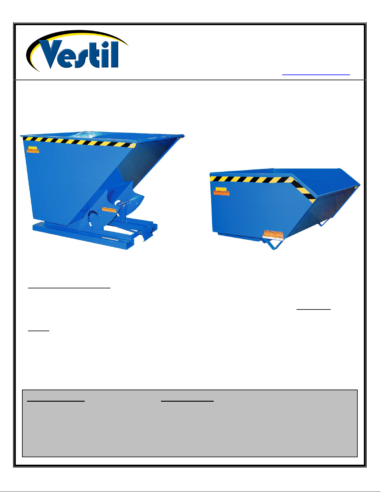
D & H-SERIES HOPPERS
VESTIL MANUFACTURING CORP.
2999 North Wayne Street, P.O. Box 507, Angola, IN 46703
Telephone: (260) 665-7586 -or- Toll Free (800) 348-0868
Fax: (260) 665-1339
www.vestilmfg.com e-mail: sales@vestil.com
Instruction Manual
D-SERIES HOPPERS H-SERIES HOPPERS
RECEIVING INSTRUCTIONS:
After delivery, IMMEDIATELY remove the packaging from the Hook-Base in a manner that preserves the
packaging and maintains the orientation of the product in the packaging; then inspect the product closely to determine
whether it sustained damage during transport. If damage is discovered during the inspection, immediately record
a complete description of the damage on the bill of lading. If the product is undamaged, discard the packaging.
NOTES:
1) Compliance with laws, regulations, codes, and non-voluntary standards enforced in the location where the product
is used is exclusively the responsibility of the owner/end-user.
2) VESTIL is not liable for any injury or property damage that occurs as a consequence of failing to apply either:
a) Instructions in this manual; or
b) Information provided on labels affixed to the product. Neither is Vestil responsible for any consequential
damages sustained as a result of failing to exercise sound judgment while assembling, installing, using or maintaining
this product.
Table of Contents Table of Figures
Product Introduction…………………… 2 – 4 Fig. 1 H-series hoppers diagram and parts list ………….................. 5
Safety Principles……………………….. 8 Fig. 2 D-series hoppers diagram and parts list.................................. 6
Safety Recommendations…………….. 8 Fig. 3 Leak proof H-hopper & parts diagram…………………………. 7
Loading instructions…………………… 9 Fig. 3 H-series markings & label placement diagram……………….. 11
Use & Operation Instructions…………. 9 Fig. 4 D-series markings & label placement diagram……………….. 12
Inspections & Maintenance…………… 10
Limited Warranty………………………. 13
Copyright 2013 Vestil Manufacturing Corp. Page 1 of 13
Page 2

11/4/2013 D & H series hoppers, manual
V
PRODUCT INTRODUCTION
Thank you for purchasing a fork-mountable, self-dumping hopper (“hopper” or “product”) made by Vestil
Manufacturing Corporation (“Vestil”). Our hoppers are durable, high-quality products that incorporate safetyconscious features. Each hopper conforms to the generalized specifications disclosed in this manual.
Standard design features include: 2 fork pockets that receive the tines (forks) of a fork truck; dump-actuating
cable that allows the hopper to be dumped by the forklift driver; and either a safety chain or safety strap to wrap
around the fork carriage and prevent the hopper from sliding off of the forks during use. Dimensions of offered
models, as well as other product specifications appear in the following table:
Model
H-series hoppers (low profile 90° self-dumping steel)
Light duty (12 gauge steel)
H-25-LD
H-50-LD
H-100-LD
H-150-LD
Medium duty (10 gauge steel)
H-25-MD
H-50-MD
H-100-MD
H-150-MD
Heavy duty (8 gauge steel)
H-25-HD
H-50-HD
H-100-HD
H-150-HD
D-series Hoppers (self-dumping steel hoppers with bumper release)
Light duty 2,000lb (909kg) maximum rated load models; fabricated from 12 gauge steel
Model
D-25-LD
D-33-LD
D-50-LD
D-75-LD
D-100-LD
D-150-LD
D-200-LD
D-250-LD
D-300-LD
olume in Cubic
Yards (m
(~0.19 m
(~0.38 m
(~0.76 m
(~1.15 m
(~0.19 m
(~0.38 m
(~0.76 m
(~1.15 m
(~0.19 m
(~0.38 m
(~0.76 m
(~1.15 m
¼
½
1
1½
¼
½
1
1½
¼
½
1
1½
3
3
)
3
)
3
)
3
)
3
)
3
)
3
)
3
)
3
)
3
)
3
)
3
)
Volume in
Cubic Yards
3
(~m
¼
(~0.19 m
1
/3
(~0.25 m
½
(~0.38 m
¾
(~0.57 m
1
(~0.76 m
1½
(~1.15 m
2
(~1.53 m
2½
(~1.91 m
3
(~2.29 m
)
3
)
3
)
3
)
3
)
3
)
3
)
3
)
3
)
3
)
Uniform Maximum
)
Rated Load in
Pounds (kg)
2,000
(~909kg)
2,000
(~909kg)
2,000
(~909kg)
2,000
(~909kg)
4,000
(~1,818kg)
4,000
(~1,818kg)
4,000
(~1,818kg)
4,000
(~1,818kg)
6,000
(~2,727kg)
6,000
(~2,727kg)
6,000
(~2,727kg)
6,000
(~2,727kg)
Hopper Inside Dimensions
in Inches (~cm)
20 x 41¼ x 27
~(50.8 x 104.8
20 x 41¼ x 27
~(50.8 x 104.8
30 x 41¼ x 27
~(76.2 x 104.8
7
/8
x 70.8)cm
7
/8
x 70.8)cm
7
/8
x 70.8)cm
28¼ x 54½ x 32½
~(71.8 x 138.4 x 82.6)cm
38 x 54¼ x 32½
~(96.5 x 138.4 x 82.6)cm
40 x 63¾ x 41½
~(71.8 x 138.4 x 82.6)cm
53 x 63¾ x 41½
~(134.6 x 162 x 105.4)cm
66¼ x 63¾ x 41½
~(168.3 x 162 x 105.4)cm
3
/16 x 63¾ x 41½
78
~(198.6
x 162 x 105.4)cm
Overall Dimensions (W x
D x H) in Inches (cm)
25 x 46 x 18
~(63.5 x 116.8 x 45.7)
25 x 51¼ x 28
~(63.5 x 130.2 x 71.1)cm
49 x 51¼ x 28
~(124.5 x 130.2 x 71.1)cm
49 x 52 x 40
~(124.5 x 132.1 x 101.6)cm
25 x 46 x 18
(63.5 x 116.8 x 45.7)
25 x 51¼ x 28
(63.5 x 130.2 x 71.1)cm
49 x 51¼ x 28
(124.5 x 130.2 x 71.1)cm
49 x 52 x 40
(124.5 x 132.1 x 101.6)cm
25 x 46 x 18
(63.5 x 116.8 x 45.7)
25 x 51¼ x 28
(63.5 x 130.2 x 71.1)cm
49 x 51¼ x 28
(124.5 x 130.2 x 71.1)cm
49 x 52 x 40
(124.5 x 132.1 x 101.6)cm
Overall Dimensions (W x
D x H) in Inches (~cm)
26 x 52 x 38
~(66 x 132.1 x 96.5)cm
26 x 52 x 38
~(66 x 132.1 x 96.5)cm
33¼ x 52 x 38
~(84.5 x 132.1 x 96.5)cm
31½ x 60½ x 43
~(80 x 153.7 x 109.2)cm
41¼ x 61 x 42
5
/
8
~(104.8 x 154.9 x108.3)cm
43¼ x 61 x 52
~(109.9 x 154.9 x 132.1)cm
56¼ x 61 x 523/8
~(142.9 x 154.9 x 133)cm)
69½ x 69 x 52
~(176.5 x 175.3 x 132.1)cm
7
/16 x 61 x 50¾
81
~(206.9 x 154.9 x 128.9)cm
Distance between
Fork Pocket Centers
in Inches (cm)
11-5/8
(~29.5cm)
11-5/8
(~29.5cm)
21-5/8
(~55cm)
21-5/8
(~55cm)
11-5/8
(~29.5cm)
11-5/8
(~29.5cm)
21-5/8
(~55cm)
21-5/8
(~55cm)
11-5/8
(~29.5cm)
11-5/8
(~29.5cm)
21-5/8
(~55cm)
21-5/8
(~55cm)
Distance between
Fork Pocket Centers
in Inches (~cm)
18
(~45.7cm)
18
(~45.7cm)
18
(~45.7cm)
18
(~45.7cm)
18
(~45.7cm)
28
(~71.1cm)
28
(~71.1cm)
28
(~71.1cm)
28
(~71.1cm)
Net Weight
in Pounds
(~99.5kg)
(~116.4kg)
(~157.7kg)
(~171.4kg)
(~104.1kg)
(~125.5kg)
(~179.5kg)
(~210.5kg)
(~98.2kg)
(~126.8kg)
(~210kg)
(~245.5kg)
Net Weight
in Pounds
(~163.6kg)
(~170.5kg)
(~186.4kg)
(~218.2kg)
(~238.2kg)
(~286.4kg)
(~329.5kg)
(~345.5kg)
(~443.2kg)
(kg)
219
256
347
377
229
276
395
463
216
279
462
540
(~kg)
360
375
410
480
524
630
725
760
975
Copyright 2013 Vestil Manufacturing Corp. Page 2 of 13
Page 3

11/4/2013 D & H series hoppers, manual
Medium duty 4,000lb (1,818kg) maximum rated load models; fabricated from 10 gauge steel
D-25-MD
D-33-MD
D-50-MD
D-75-MD
D-100-MD
D-150-MD
D-200-MD
D-250-MD
D-300-MD
¼
(~0.19 m
1
/3
(~0.25 m
½
(~0.38 m
¾
(~0.57 m
1
(~0.76 m
1½
(~1.15 m
2
(~1.53 m
2½
(~1.91 m
3
(~2.29 m
3
)
3
)
3
)
3
)
3
)
3
)
3
)
3
)
3
)
20 x 41¼ x 27
~(50.8 x 104.8
20 x 41¼ x 27
~(50.8 x 104.8
30 x 41¼ x 27
~(76.2 x 104.8
28¼ x 54½ x 32½
~(71.8 x 138.4 x 82.6)cm
38 x 54¼ x 32½
~(96.5 x 138.4 x 82.6)cm
40 x 63¾ x 41½
~(71.8 x 138.4 x 82.6)cm
53 x 63¾ x 41½
~(134.6 x 162 x 105.4)cm
66¼ x 63¾ x 41½
~(168.3 x 162 x 105.4)cm
3
78
/16 x 63¾ x 41½
~(198.6
x 162 x 105.4)cm
Heavy duty 6,000lb (2,727kg) maximum rated load models; fabricated from 8 gauge steel
D-25-HD
D-33-HD
D-50-HD
D-75-HD
D-100-HD
D-150-HD
D-200-HD
D-250-HD
D-300-HD
D-350-HD
¼
(~0.19 m
1
/3
(~0.25 m
½
(~0.38 m
¾
(~0.57 m
1
(~0.76 m
1½
(~1.15 m
2
(~1.53 m
2½
(~1.91 m
3
(~2.29 m
3½
(~2.68 m
3
)
3
)
3
)
3
)
3
)
3
)
3
)
3
)
3
)
3
)
20 x 41¼ x 27
~(50.8 x 104.8
20 x 41¼ x 27
~(50.8 x 104.8
30 x 41¼ x 27
~(76.2 x 104.8
28¼ x 54½ x 32½
~(71.8 x 138.4 x 82.6)cm
38 x 54¼ x 32½
~(96.5 x 138.4 x 82.6)cm
40 x 63¾ x 41½
~(71.8 x 138.4 x 82.6)cm
53 x 63¾ x 41½
~(134.6 x 162 x 105.4)cm
66¼ x 63¾ x 41½
~(168.3 x 162 x 105.4)cm
3
78
/16 x 63¾ x 41½
~(198.6
x 162 x 105.4)cm
88¼ x 63¾ x 41½
~(224.2 x 162 x 105.4)cm
7
/8
x 70.8)cm
7
/8
x 70.8)cm
7
/8
x 70.8)cm
7
/8
x 70.8)cm
7
/8
x 70.8)cm
7
/8
x 70.8)cm
26 x 52 x 38
~(66 x 132.1 x 96.5)cm
26 x 52 x 38
~(66 x 132.1 x 96.5)cm
33¼ x 52 x 38
~(84.5 x 132.1 x 96.5)cm
31½ x 60½ x 43
~(80 x 153.7 x 109.2)cm
41¼ x 61 x 42
5
/
8
~(104.8 x 154.9 x108.3)cm
43¼ x 61 x 52
~(109.9 x 154.9 x 132.1)cm
56¼ x 61 x 523/8
~(142.9 x 154.9 x 133)cm)
69½ x 69 x 52
~(176.5 x 175.3 x 132.1)cm
7
81
/16 x 61 x 50¾
~(206.9 x 154.9 x 128.9)cm
26 x 52 x 38
~(66 x 132.1 x 96.5)cm
26 x 52 x 38
~(66 x 132.1 x 96.5)cm
33¼ x 52 x 38
~(84.5 x 132.1 x 96.5)cm
31½ x 60½ x 43
~(80 x 153.7 x 109.2)cm
41¼ x 61 x 42
5
/
8
~(104.8 x 154.9 x108.3)cm
43¼ x 61 x 52
~(109.9 x 154.9 x 132.1)cm
56¼ x 61 x 523/8
~(142.9 x 154.9 x 133)cm)
69½ x 69 x 52
~(176.5 x 175.3 x 132.1)cm
7
81
/16 x 61 x 50¾
~(206.9 x 154.9 x 128.9)cm
92 x 69 x 52
~(233.7 x 175.3 x 132.1)cm
18
(~45.7cm)
18
(~45.7cm)
18
(~45.7cm)
18
(~45.7cm)
18
(~45.7cm)
28
(~71.1cm)
28
(~71.1cm)
28
(~71.1cm)
28
(~71.1cm)
18
(~45.7cm)
18
(~45.7cm)
18
(~45.7cm)
18
(~45.7cm)
18
(~45.7cm)
28
(~71.1cm)
28
(~71.1cm)
28
(~71.1cm)
28
(~71.1cm)
28
(~71.1cm)
(~177.3kg)
(~190.9kg)
(~238.6kg)
(~284.1kg)
(~304.5kg)
(~331.8kg)
(~361.4kg)
(~450.5kg)
(~186.4kg)
(~190.9kg)
(~206.8kg)
(~254.5kg)
(~281.8kg)
(~338.6kg)
(~353.6kg)
(~404.5kg)
(~450.5kg)
(~504.5kg)
Options
Model Description Net Weight
H-DAMP-4
H-DAMP-6
LEKP
D-DPLG-1
D-DPLG-2
H-DPLG-1
H-DPLG-2
LUG
Hopper dumping speed regulator for 4,000lb (medium duty) models 30 lb. (13.6kg)
Hopper dumping speed regulator for 6,000lb (heavy duty) models 40 lb. (18.2kg)
“Leak proof” welded hopper 5 lb. (2.3kg)
1in. drain plug option 2 lb. (0.9kg)
2in. drain plug option 2 lb. (0.9kg)
1in. drain plug option 2 lb. (0.9kg)
2in. drain plug option 2 lb. (0.9kg)
4 welded lifting lugs (around perimeter of hopper mouth) 150 lb. (68.2kg)
385
(~175kg)
390
420
525
625
670
730
795
991
410
420
455
560
620
745
778
890
991
1,110
Copyright 2013 Vestil Manufacturing Corp. Page 3 of 13
Page 4

11/4/2013 D & H series hoppers, manual
Heavy-duty polyethylene lids
Model
PLID-H-25 1 37-024-038-004 H-25-LD, H-25-MD, H-25-HD 7 (3.2kg)
PLID-H-50 1 37-024-038-003 H-50-LD, H-50-MD, H-50-HD 8 (3.6kg)
PLID-H-100 2 37-024-038-002 H-100-LD, H-100-MD, H-100-HD 14 (6.4kg)
PLID-H-150 2 37-024-038-001 H-150-LD, H-150-MD, H-150-HD 16 (7.3kg)
PLID-D-33 1 37-024-087-002 D-33-LD, D-33-MD, D-33-HD 7 (3.2kg)
PLID-D-50 1 37-024-087-001 D-50-LD, D-50-MD, D-50-HD 8 (3.6kg)
PLID-D-75 1 37-024-086-002 D-75-LD, D-75-MD, D-75-HD 9 (4.1kg)
PLID-D-100 1 37-024-086-001 D-100-LD, D-100-MD, D-100-HD 10 (4.5kg)
PLID-D-150 1 37-024-085-004 D-150-LD, D-150-MD, D-150-HD 14 (6.4kg)
PLID-D-200 2 37-024-085-003 D-200-LD, D-200-MD, D-200-HD 16 (7.3kg)
PLID-D-250 2 37-024-085-002 D-250-LD, D-250-MD, D-250-HD 18 (8.2kg)
PLID-D-300 2 37-024-085-001 D-300-LD, D-300-MD, D-300-HD 20 (9.1kg)
Number of
Pieces
Part Number Fits Hopper Models
Net Weight in
Pounds (kg)
Caster kits
Model
HOP-SC6-2
HOP-SC8-2
HOP-RC6-2
HOP-RC8-2
HOP-PC6-2
HOP-PC8-2
HOP-PHC6-2
HOP-PHC8-2
HOP-SC6-2.5
NOTE: “Uniform capacity” is the maximum weight that each caster set can support, and equals the combined weight of the
hopper and it contents. ONLY select a caster kit that equals or exceeds the maximum rated load of your hopper!
Dimensions in
Inches (cm)
6 x 2
(15¼ x 5.1)cm
8 x 2
(20.3 x 5.1)cm
6 x 2
(15¼ x 5.1)cm
8 x 2
(20.3 x 5.1)cm
6 x 2
(15¼ x 5.1)cm
8 x 2
(20.3 x 5.1)cm
6 x 2
(15¼ x 5.1)cm
8 x 2
(20.3 x 5.1)cm
6 x 2½
(15¼ x 6.4)cm
Uniform Capacity
in Pounds (kg)
4,800
(2,182kg)
4,800
(2,182kg)
2,400
(1,091kg)
2,400
(1,091kg)
4,800
(2,182kg)
4,800
(2,182kg)
4,800
(2,182kg)
4,800
(2,182kg)
6,000
(2,727kg)
Caster Material
Quantity
per Order
Semi-steel 4
Semi-steel 4
Mold-on rubber 4
Mold-on rubber 4
Polyurethane on steel 4
Polyurethane on steel 4
Glass-filled nylon 4
Glass-filled nylon 4
Steel 4
Net Weight in
Pounds (kg)
33
(15kg)
42
(19.1kg)
28
(12.7kg)
37
(16.8kg)
33
(15kg)
42
(19.1kg)
37
(16.8kg)
54
(24.5kg)
65
(29.5kg)
Copyright 2013 Vestil Manufacturing Corp. Page 4 of 13
Page 5

11/4/2013 D & H series hoppers, manual
Fig. 1: H-series hoppers diagram and parts list
Release latch bar
Pivot pin channel
Release latch
lever
Item
Part no. Description Quantity
no.
1 37-514-005 Base frame weldment 1
2 37-545-008 Hopper chute weldment 1
3 37-537-010 Chute release lever weldment 1
4 37-146-005 Release torsion spring 1
5 37-145-002 5/16in. x 57½in. safety chain 1
6 45214
7 29-048-061 Rubber pumper 1
8 11061
9 37-112-045 Pivot pin 2
10 65127
11 33006
12 37021
5
/16in. quick link 2
5
/16in. – 18 x 2in. HHCS zinc-plated bolt 2
3
/16in. x 2in. zinc-plated cotter pin 3
5
/16in. USS zinc-plated flat washer 2
5
/16in. – 18 nylock nut 2
3
4
6
5
Copyright 2013 Vestil Manufacturing Corp. Page 5 of 13
3
2
10
7 8 11 12
1
Page 6

11/4/2013 D & H series hoppers, manual
5
3
3
5
Fig. 2: D-series hoppers diagram and parts list
Item
No.
Part No. Description Quantity
1 37-514-004 Base frame weldment 1
2 37-545-046 Chute weldment 1
3 37-112-007 Pivot pin 1
4 37-537-006 Release lever rod weldment 1
5 37-112-006 Bumper plate pin 1
6 37-146-005 Chute release torsion spring 2
7 45214
8 65125
/16in. quick link 1
/
in. x 1½ in. zinc-plated cotter pin 1
16
9 01-112-009 Hinge pin 2
10 68015 ¾ in. external retaining ring 3
11 64141
/
in. x 2 in. spring pin 1
16
12 37-537-010 Chute release assembly 1
13 37-037-040 Chute release bumper plate 1
14 37-145-004
/16in. x 48in. safety chain 1
12
5
1
7 8 9
3
5
10
13
2
13
1 3
Copyright 2013 Vestil Manufacturing Corp. Page 6 of 13
Page 7

11/4/2013 D & H series hoppers, manual
FIG. 3: Leak Proof H-Hopper (Option LEKP) Diagram and Parts List
3
2
8
1 6 7 4 5
Item no. Part no. Description Quantity
1 S929134-F1 Leak proof base frame weldment 1
2 S929134-C1A Leak proof chute weldment 1
3 37-537-012 Release lock lever assembly 1
4 S929134-CYL1-B 1 in. x 14 in. hydraulic cylinder body 1
5 S929134-CYL1-R 1 in. x 14 in. hydraulic cylinder rod 1
6 S929134-P4B Cylinder pin (body end) 1
7 S929134-P4A Cylinder pin (rod end) 1
chute and cause it to no longer be watertight. Similarly, do not allow water to accumulate in the chute, which will
allow rust to develop. Rinse the hopper chute after emptying contents, and dry the chute before filling it again.
8 37-112-003 Hinge axle pin hoppers (H style) 1
DO NOT put or store corrosive substances in the chute of a hopper. Corrosion will damage the
To dump a leak-proof H-hopper, simply pull the release lever. Once released, the cylinder will extend until the
chute dumps. Manually return the chute to the latched position.
Copyright 2013 Vestil Manufacturing Corp. Page 7 of 13
Page 8

11/4/2013 D & H series hoppers, manual
SAFETY PRINCIPLES
Vestil Manufacturing Corp. created this manual to acquaint owners and users of our fork-mounted hoppers with safe use and
maintenance procedures. Although Vestil diligently strives to identify foreseeable, hazardous situations, this manual cannot
address every conceivable danger. The end-user is ultimately responsible for exercising sound judgment at all times.
The mechanisms of each hopper are relatively intuitive to operate. Nonetheless, all persons who might use or operate this
product should familiarize themselves with the instructions provided in this manual. Each person who might use or maintain the
product must read this entire manual and fully understand the directions BEFORE using or performing maintenance on the
hopper.
Failure to apply the directions in this manual might lead to serious personal injury or even death. Vestil is not liable
for any injury or property damage that occurs as a consequence of failing to apply either: 1) the instructions that appear in this
manual; or 2) the information disclosed on labels affixed to the product. Furthermore, failure to exercise good judgment and
common sense could result in property damage, serious personal injury or death, and also are not the responsibility of Vestil.
To draw attention to hazards that users might encounter, this manual classifies personal injury risks and situations that could
lead to property damage with SIGNAL WORDS. These signal words announce an associated safety message. The reader must
understand that the signal word chosen indicates the seriousness of the described hazard.
Identifies a hazardous situation which, if not avoided, WILL result in DEATH or SERIOUS
Identifies a hazardous situation which, if not avoided, COULD result in DEATH or SERIOUS
Indicates a hazardous situation which, if not avoided, COULD result in MINOR or MODERATE
Identifies practices likely to result in product/property damage, such as operation that might damage
Safety Recommendations:
Study the entire manual before using the product for the first time. Read the manual when necessary to refresh your
understanding of the safe operation, inspection and maintenance procedures explained on p.9. If questions remain after you
finish reading this manual, ask your supervisor or employer for assistance. DO NOT attempt to resolve any problems with the
boom unless you are authorized to do so and are certain that it will be safe to use afterwards.
INJURY. Use of this signal word is limited to the most extreme situations.
INJURY.
injury.
the hopper.
Electrocution might result if the hopper contacts electrified wires. Reduce the likelihood that an operator or
bystander might be electrocuted by applying common sense:
DO NOT contact electrified wires with the hopper or any part of the forklift truck.
DO NOT use the hopper in an area where it will contact electrified wires.
Before using the hopper, always inspect the usage area for unusual conditions that require special precautions.
Material handling is dangerous. Improper or careless operation might result in serious personal injuries
sustained by the hopper/forklift operator(s) and bystanders. Reduce the likelihood of injury boom operators by applying the
following:
Failure to read and understand the instructions included in this manual before using or servicing the hopper constitutes
misuse.
DO NOT use a malfunctioning or structurally damaged hopper. Examples structural damage include: 1) damage to the
hopper release mechanism (that allows the hopper to dump); 2) broken fork pocket(s); 3) main connection pin; or 4)
broken welds. Inspect the hopper before each use according to the inspection instructions on p. 9. DO NOT use the
hopper unless it passes every part of the inspection.
DO NOT use the hopper if the safety chain is damaged or absent; DO NOT lift the hopper until it is securely connected
to the carriage of the fork truck with the safety chain.
DO NOT fill the hopper with a load weighing more than the maximum rated load (see Table, p. 2-3).
DO NOT stand beneath or travel under the hopper at any time. DO NOT permit any person to stand beneath or travel
under the hopper.
DO NOT allow people to ride on or in the hopper.
DO NOT use the hopper if any product label (see p. 10 or 11) is unreadable, damaged, or missing. Contact Vestil to
order replacement labels.
ALWAYS apply proper (fork) lift truck operation practices learned during your training program. Before raising the
hopper from the floor AND tilt the (forklift) mast toward the cab of the truck to ensure that the hopper will not slide
towards the tips of the forks.
DO NOT modify the hopper in any way! Modification(s) might make the hopper unsafe to use.
DO NOT dump the hopper UNLESS every person in the vicinity is safely behind the forklift truck.
DO NOT dump the hopper if the forklift is facing down a slope. Only dump the hopper while parked on a level surface.
Copyright 2013 Vestil Manufacturing Corp. Page 8 of 13
Page 9

11/4/2013 D & H series hoppers, manual
Loading instructions:
Verify that the hopper chute is latched to the base frame, i.e. NOT released and cannot rotate, before filling the chute
with refuse. Warning: Do not exceed the dumper’s (and if portable, its casters’) load ratings or fill the hopper above the top
of the hopper’s sides. Injury to personnel or permanent damage to the equipment could result from overloading.
Standard D-series and H-series self-dumping hoppers are suitable for use indoors and outdoors and in most industrial
and commercial settings. They are intended for use in conjunction with a rider forklift truck as a means to dump nonhazardous refuse into larger trash receptacles.
D-series hoppers: the chute rotates through a 70° dump angle. To dump the hopper, the forklift operator can either
1. Press the bumper release plate (Item no. 13 on p. 6) on the front of the hopper by driving the forklift forward until
the side of the dumpster presses against the bumper plate and releases the chute; or
2. Manually release the chute from the forklift cab by pulling the release cable.
H-series hoppers: the low-profile hopper rotates through a 90° dump angle. To dump the hopper, the forklift operator
must simply pull the release cable.
Use and Operation instructions:
Step 1: Drive the forklift forward to insert the forks into the fork pockets. Continue driving forward until the forks are
completely inserted.
D-series: drive as far forward as possible;
H-series: drive forward until the forks contact the caps at the ends of the fork pockets.
Step 2: Securely attach the hopper to the fork carriage with the safety chain (item no. 5 on p. 5; item no. 14 on p. 6). Wrap
the chain around part of the fork carriage; then connect the quick link at the end of the chain to a link in the chain with as
little slack as possible.
DO NOT wrap the release cable around any part of your body, especially your hand(s), or attach the
handle at the end of the cable to your clothing. If you do and the chute is released, you might be seriously injured.
Step 3: Store the handle of the release cable within reach of the forklift operator, for instance, by hooking it to the frame of
the cab. Make sure that there is plenty of slack in the cable to avoid accidentally releasing/dumping the chute.
Step 4: Drive the forklift to the trash receptacle; then tilt the mast of the forklift forward and raise the forks. Elevate the
hopper to a height as shown in the diagrams below:
H-series D-series
Back end of chute
Top of side wall of
dumpster/receptacle
Interior cavity
of dumpster
Step 5: Dump the contents of the hopper by releasing the chute. To release the chute, pull the release cable. For D-series
hoppers, an alternative method of releasing the chute is to drive the forklift toward the dumpster and contact the chute
release bumper plate (item no. 13 on p. 6) with the top of the side wall of the dumpster.
Step 6: Return the chute to the latched position. Tilt the forklift mast toward the cab; then back away from the dumpster.
D-series hoppers automatically return to the latched position. For H-series hoppers, lower the forks until the hopper
contacts the ground; then slowly lower the forks the rest of the way to the ground until the chute latches to the base frame.
Confirm that the chute is properly latched by raising the forks. The chute should not rotate. If necessary, lower the forks
completely and manually latch the chute to the frame by pressing down on the back of the chute (see “H-series” diagram
in Step 4).
Back end of chute
Top of
dumpster
side wall
Chute release bumper plate
Interior cavity
of dumpster
Copyright 2013 Vestil Manufacturing Corp. Page 9 of 13
Page 10

11/4/2013 D & H series hoppers, manual
Inspections & Maintenance:
Inspection and maintenance personnel should immobilize the boom before either conducting inspections or
performing maintenance. The boom is properly immobilized if it cannot tip over.
If one or more problem is discovered during an inspection, restore the hopper to normal operating condition
BEFORE using it again. DO NOT use a structurally damaged hopper. Structural damage includes, but is not limited to,
cracked welds, warping or deformation of one or both of the fork pockets, chute, pivot points, or frame members.
Inspections:
(A) Before each use inspect the following components:
1.) Release cable – fraying, birdcaging, thinning;
2.) Hopper chute or base frame – damage, deformation, corroded or excessively rusted regions;
3.) Pivot points – unusual noise or binding (when chute rotates), distortion of pivot pin or pivot pin
channels (see Figures 1 and 2 on p. 5 & 6);
4.) Release/Latch mechanisms – torsion spring should cause the chute release lever weldment (item
number 3 on p. 5; item no. 3 on p. 6) to automatically recoil; the release latch should firmly engage
the release lock bar proper function;
5.) Hopper retaining mechanisms – look for evidence of fatigue or damage to the safety chain, the point
of attachment to the base frame, or the quick links.
(B) Inspect the following components at least once per month and replace any component that is excessively worn or
no longer operates normally:
1.) Pivot points – look for excessive wear, warping, or other significant damage to pivot pins, cotter pins
that retain pivot pins in place, or pin channels (see Figures 1 and 2 on p. 5 & 6).
2.) Fasteners (bolts, nuts, pins, cotter pins, retaining rings) – inspect for looseness and wear.
3.) Casters – check for looseness, excessive wear, or damage to the casters, caster bearings, mounting
brackets, or hardware.
4.) Release mechanism – verify that the mechanisms function properly. The torsion spring should cause
the chute release lever weldment (item number 3 on p. 5 & 6) to automatically recoil; the release latch
should firmly engage the release lock bar proper function;
5.) All moving parts – listen for unusual noises and watch for irregular movement. Remove dirt and
debris from areas that could affect the hopper’s dumping motion;
6.) Labels – all labels must be firmly affixed in the locations shown in Fig. 3 or 4 on p. 10 or 11.
Maintenance:
The end-user, i.e. operators and employers, should implement a maintenance program to ensure that the product
functions properly and is adequately maintained. The following steps should be applied to complement established
maintenance programs.
The end-user is responsible for selecting and training employees to work on the hopper. ONLY
trained, authorized maintenance personnel or contractors should inspect, maintain, or repair the hopper.
Step 1: Tag the hopper, “Out of Service.”
Step 2: Remove any dirt or other matter from all surfaces.
Step 3: Conduct a “Before each use” inspection. If deformity, corrosion, rusting, or excessive wear of structural
members is found, DO NOT use the product.
Step 4: Perform all other necessary adjustments, replacements and/or repairs, but DO NOT modify the hopper.
The reader should understand the significant difference between necessary adjustments and
repairs, and modifications.
An “adjustment” is a simple correction that restores the hopper to normal operating condition, such as
tightening loose fasteners, or removing dirt or other debris from the surface. “Repair” means removing worn parts
and installing new replacement parts.
DO NOT use the hopper if adjustments and/or repairs are incomplete! Return it to service ONLY after
finishing all necessary repairs and adjustments.
A “modification” is a change that alters the hopper from normal operating condition, like bending the structural
members or removing a part or several parts. NEVER modify the hopper unless you are certain that the hopper
will be safe to use afterwards, or without first obtaining express, written approval from Vestil. Modifications might
make the hopper unsafe to use.
Step 5: Make a dated record of any repairs, adjustments and/or replacements.
Copyright 2013 Vestil Manufacturing Corp. Page 10 of 13
Page 11

11/4/2013 D & H series hoppers, manual
Fig. 3: H-series markings & label placement diagram
Copyright 2013 Vestil Manufacturing Corp. Page 11 of 13
Page 12

11/4/2013 D & H series hoppers, manual
Fig. 4: D-series markings & label placement diagram
Copyright 2013 Vestil Manufacturing Corp. Page 12 of 13
Page 13

11/4/2013 D & H series hoppers, manual
LIMITED WARRANTY
Vestil Manufacturing Corporation (“Vestil”) warrants this product to be free of defects in material and workmanship
during the warranty period. Our warranty obligation is to provide a replacement for a defective original part if the part
is covered by the warranty, after we receive a proper request from the warrantee (you) for warranty service.
Who may request service?
Only a warrantee may request service. You are a warrantee if you purchased the product from Vestil or from an
authorized distributor AND Vestil has been fully paid.
What is an “original part”?
An original part is a part used to make the product as shipped to the warrantee.
What is a “proper request”?
A request for warranty service is proper if Vestil receives: 1) a photocopy of the Customer Invoice that displays the
shipping date; AND 2) a written request for warranty service including your name and phone number. Send requests
by any of the following methods:
Mail Fax Email
Vestil Manufacturing Corporation (260) 665-1339 sales@vestil.com
2999 North Wayne Street, PO Box 507 Phone
Angola, IN 46703 (260) 665-7586
In the written request, list the parts believed to be defective and include the address where replacements should be
delivered.
What is covered under the warranty?
After Vestil receives your request for warranty service, an authorized representative will contact you to determine
whether your claim is covered by the warranty. Before providing warranty service, Vestil may require you to send the
entire product, or just the defective part or parts, to its facility in Angola, IN. The warranty covers defects in the
following original dynamic components: motors, hydraulic pumps, electronic controllers, switches and cylinders. It
also covers defects in original parts that wear under normal usage conditions (“wearing parts”): bearings, hoses,
wheels, seals, brushes, batteries, and the battery charger.
How long is the warranty period?
The warranty period for original dynamic components is 1 year. For wearing parts, the warranty period is 90 days.
Both warranty periods begin on the date when Vestil ships the product to the warrantee. If the product was purchased
from an authorized distributor, the periods began when the distributor shipped the product. Vestil may extend the
warranty period for products shipped from authorized distributors by up to 30 days to account for shipping time.
If a defective part is covered by the warranty, what will Vestil do to correct the problem?
Vestil will provide an appropriate replacement for any covered part. An authorized representative of Vestil will contact
you to discuss your claim.
What is not covered by the warranty?
1. Labor;
2. Freight;
3. Occurrence of any of the following, which automatically voids the warranty:
Product misuse;
Negligent operation or repair;
Corrosion or use in corrosive conditions;
Inadequate or improper maintenance;
Damage sustained during shipping;
Accidents involving the product;
Unauthorized modifications: DO NOT modify the product IN ANY WAY without first receiving
written authorization from Vestil. Modification(s) might make the product unsafe to use or might
cause excessive and/or abnormal wear.
Do any other warranties apply to the product?
Vestil Manufacturing Corp. makes no other express warranties. All implied warranties are disclaimed to the extent
allowed by law. Any implied warranty not disclaimed is limited in scope to the terms of this Limited Warranty.
Copyright 2013 Vestil Manufacturing Corp. Page 13 of 13
 Loading...